

Page 1
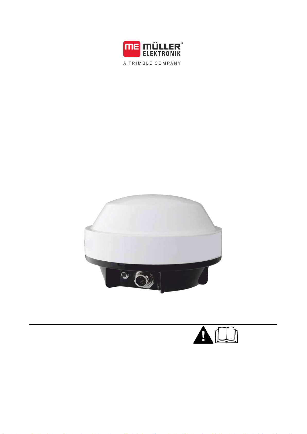
Installation and Operating Instructions
DGPS Receiver A101
Version: V5.20180409
3030246900-02-EN
Read and follow these operating instructions.
Keep these operating instructions in a safe place for
later reference.
Page 2

Document
Copyright ©
Company details
Installation and Operating Instructions
Product: DGPS Receiver A101
Document number: 3030246900-02-EN
Original language: German
Müller-Elektronik GmbH & Co.KG
Franz-Kleine-Straße 18
33154 Salzkotten
Germany
Phone: ++49 (0) 5258 / 9834 - 0
Fax: ++49 (0) 5258 / 9834 - 90
Email: info@mueller-elektronik.de
Homepage: http://www.mueller-elektronik.de
Page 3

Table of contents
V5.20180409
3
1
For your safety
4
1.1
Basic safety instructions
4
1.2
Intended use
4
1.3
Layout and meaning of warnings
4
1.4
Disposal
5
1.5
Cleaning
5
2
Product description
6
2.1
About the GPS receiver
6
2.2
Meaning of the LED lights
6
3
Mounting and configuration
7
3.1
Mounting the GPS receiver
7
3.2
Connecting the GPS receiver to a terminal
8
3.3
Configuring the GPS receiver
8
4
Technical specifications
9
5
List of accessories
10
Table of contents
Page 4

1
For your safety
Basic safety instructions
4
3030246900-02-EN
WARNING
This signal word identifies medium-risk hazards, which could potentially cause
death or serious physical injury, if not avoided.
CAUTION
This signal word identifies hazards that could potentially cause minor or moderate
physical injury or damage to property, if not avoided.
1
1.1
1.2
1.3
For your safety
Basic safety instructions
Please read the following safety instructions carefully before using the product for
the first time.
▪ Do not make any unauthorized modifications to the product. Unauthorized
modifications or use may impair safety and reduce the service life or operability
of the unit. Modifications are considered unauthorized if they are not described
in the product documentation.
▪ Comply with road traffic rules. Stop the vehicle before operating the GPS
receiver or connected components.
Intended use
The product is intended for accurate positioning of agricultural vehicles.
The product is only intended for use in the agricultural sector. The manufacturer
shall not be held responsible for any other use of the system.
The operating instructions form part of the product. The product may only be used in
accordance with these operating instructions.
The manufacturer cannot be held liable for any personal injury or property damage
resulting from such non-compliance. All risk arising from improper use lies with the
user.
Layout and meaning of warnings
All safety instructions found in these Operating Instructions are composed in
accordance with the following pattern:
Page 5

For your safety
Disposal
1
V5.20180409
5
NOTICE
This signal word identifies hazards that could potentially cause damage to property,
if not avoided.
When it has reached the end of its service life, please dispose of this
product as electronic scrap in accordance with all applicable waste
management laws.
Example
1.4
1.5
There are some actions that need to be performed in several steps. If there is a risk
involved in carrying out any of these steps, a safety warning appears in the
instructions themselves.
Safety instructions always directly precede the step involving risk and can be
identified by their bold font type and a signal word.
1. NOTICE! This is a notice. It warns that there is a risk involved in the next
step.
2. Step involving risk.
Disposal
Cleaning
Do not clean the product with a high pressure cleaner to prevent moisture from
entering the connector.
Page 6

2
Product description
About the GPS receiver
6
3030246900-02-EN
GPS receiver A101
Connector cable
A different cable may be provided.
Metal plate
Adhesive plate
Magnetic pedestal
2
2.1
2.2
Product description
About the GPS receiver
The DGPS receiver is used to determine the exact position of a vehicle during field
work.
Meaning of the LED lights
The DGPS receiver has a status LED, which shows the quality of the connection:
▪ Red: DGPS receiver is connected to the terminal, but is unable to receive a GPS
signal.
▪ Orange: DGPS receiver can receive GPS signals, but has no differential signal.
Its accuracy is very low, and cannot be used for precision farming.
▪ Green: DGPS receiver can receive GPS signals and the differential signal.
Page 7

Mounting and configuration
Mounting the GPS receiver
3
V5.20180409
7
Adhesive plate
Metal plate
Magnetic pedestal
DGPS receiver A101
CAUTION
Crushing hazard due to very powerful magnet
The magnetic pedestal of the GPS receiver incorporates a very powerful magnet.
◦ Never place your fingers between the magnetic pedestal of the GPS receiver
and a metal surface.
◦ Hold the GPS receiver firmly in your hands, but do not place your fingers under
the magnetic pedestal.
NOTICE
The GPS receiver needs an open view of the sky.
◦ Mount the GPS receiver on the roof of the vehicle cab.
◦ Avoid shadowing the GPS receiver's view of the sky.
3
3.1
Mounting and configuration
Mounting the GPS receiver
Mounting accessories
DGPS receiver on the roof of a tractor
Page 8

3
Mounting and configuration
Connecting the GPS receiver to a terminal
8
3030246900-02-EN
NOTICE
Terminal connector supplying power
Potential damage to the terminal from a short-circuit.
◦ Switch the terminal off before plugging in or removing the connector.
Procedure
3.2
Procedure
3.3
1. Find a suitable place on the vehicle roof. This place should be as far to the front
as possible and in the middle of the vehicle.
2. Use alcohol to clean the place where you will mount the DGPS receiver.
3. Stick the provided 3M double-sided adhesive tape onto the clean surface.
4. Clean the provided metal plate.
5. Remove the protective paper from the 3M adhesive plate and bond the metal
plate onto this.
6. Screw the magnetic pedestal onto the DGPS receiver.
7. Place the DGPS receiver with the magnetic pedestal onto the metal plate.
Connecting the GPS receiver to a terminal
This is how you connect the DGPS receiver to a terminal:
1. Switch off the terminal.
2. Guide the cable of the GPS receiver into the vehicle cab.
3. Find the appropriate RS232 connection on the terminal. Refer to the operating
instructions for the terminal to find out which connection this is. For the majority
of terminals from Müller-Elektronik, this is going to be port C.
4. During initial start-up it can take approx. 30 minutes until the DGPS receiver has
reception. At subsequent start-ups it will only take approx. 1-2 minutes.
Configuring the GPS receiver
The DGPS receiver can be configured differently for various terminals.
To find out about which parameters you must configure and how, read the operating
instructions for the terminal and the applications which will use the DGPS receiver.
Page 9

Technical specifications
4
V5.20180409
9
Operating voltage
7 - 36V DC
Current consumption
249mA at 12V DC
Power input
< 3W at 12 V DC
GPS standard
NMEA 0183
Frequencies
5 Hz (GPGGA, GPVTG)
1 Hz (GPGSA, GPZDA)
Transmission rate
19200 baud
Data bits
8
Parity
No
Stop bits
1
Flow control
None
4
Technical specifications
Configuration
Properties
Page 10

5
List of accessories
10
3030246900-02-EN
Item number
Item name
3030246900
DGPS receiver A101 for WAAS and EGNOS
Connector cable to the terminal: 6m
3030246901
DGPS receiver A101 for WAAS and EGNOS
Connector cable to the terminal: 12m
3030246905
DGPS receiver A101 for WAAS and EGNOS
Connector cable to the steering job computer
Item number
Item name
3130246900
DGPS receiver A101 for WAAS and EGNOS
3130246905
DGPS receiver A101 with no cable for the steering job computer
Item number
Item name
31302462
Connector cable to the terminal: 6m
31302468
Connector cable to the terminal: 12m
31302464
Connector cable from A101 to the steering job computer
31302457
Connector cable to the terminal: 6m, with a cable for transferring the GPS speed
signal. e.g. for a spray nozzle
31302451
Connector cable to the terminal, with a cable for connection to the steering job
computer and a cable for transferring the GPS speed signal. e.g. for a spray nozzle
31302459
Y-adapter cable for parallel connection to two terminals for cable 31302462 or
31302468.
31300557
Dust protection cap for the connector cable
5
List of accessories
Complete package - DGPS receiver with cable for WAAS and EGNOS
GPS receiver with no connector cable
Connector cable
 Loading...