

Mulholland WALKABOUT 1, WALKABOUT 2 User Manual
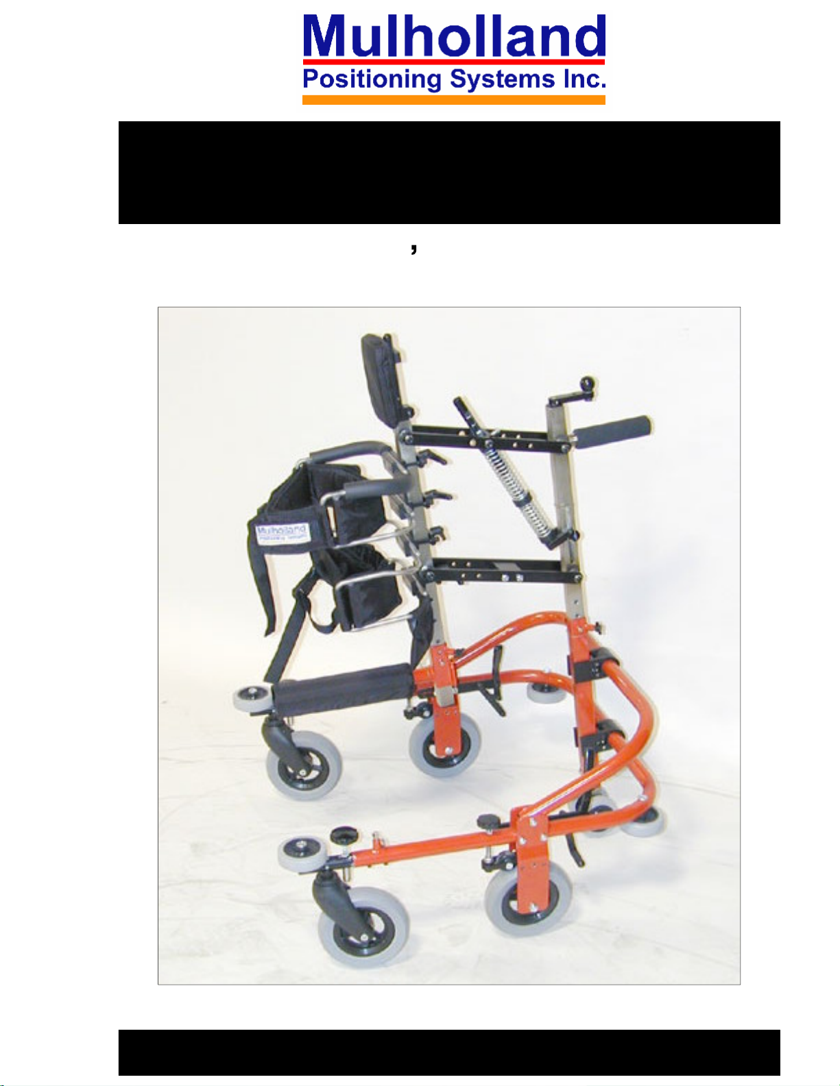
WALKABOUT
User s Manual
TM
1 & 2C
1

TABLE OF CONTENTS
Preface
Design Goals
Precautions
Program Recommendations
Components
Assembly 6-8
Adjustment Overview
Fitting Instructions
Measure the Child
Sit Bar, Hip & Upper Trunk Supports
Upper Body Pitch
Column Height
3
3
3
P
4-5
9
4
10-15
10
10-11
11
12
Spring Tension
Swivel Caster Lock
Adjustable Length Base
Headrest
No-Back Brakes
Options
Hand Holds & Arm Troughs
Clear Tray Assembly
Double Sit Bar
Abduction Skirt
Unicycle Saddle Seat
Neckrest
13
14
14
15
15
16-21
16
17
18
18
19
20
2
Shoulder Pads
Operating Precautions
Maintenance
Technical Data
20-21
22
22
23

PREFACE
This booklet provides the information required for the set
up and use of the Walkabout
using this system can be profound, not only in terms of gait
development, but also in terms of increasing the child s
independence, self confidence and social interaction.
DESIGN GOALS
The WalkaboutTM is designed to give a child the potential
for hands-free, self-initiated movement while providing
lateral support and assisted lift. This spring
allows for graduated weight relief as the child develops
TM
1 & 2C. The benefits of
-assisted lift
skill and standing tolerance. The adjustable pitch of the
column, along with the pelvic and trunk supports, can be
utilized to direct weight shift and assist with stepping.
PRECAUTIONS
1.
This stander should be used under the prescription of the
child s physician and under the direction of the child s
therapist. Often, ankle support is required prior to
utilization of this equipment.
2.
Never leave the child unattended!
supervision at all times.
3.
This stander is designed for use on level surfaces only.
4.
Do not use for transportation.
Maintain adult
5.
Adjust the frame length to suit conditions of use. A short
base used during play or out-of-doors can be
6.
Periodically check and tighten all loose fasteners. Loose
fasteners can cause the WalkaboutTM to be inoperable.
unstable.
3

PROGRAM RECOMMENDATIONS
Initially, many children use the WalkaboutTM as a
stationary stander to develop standing tolerance and to
develop hip and knee extension. Remember that spasticity
has nothing to do with strength. A child with weak hip
flexors may utilize their adductors to assist (this is not a
good thing!) This situation can become more severe if the
child has limited dorsiflexion. Try activities such as
kicking or marching.
Arrange obstacle courses to develop motor planning skills.
Whenever possible, integrate the child while in the
TM
Walkabout
ball, family chores , ice-
into peer appropriate activities: soccer, T
skating, etc.
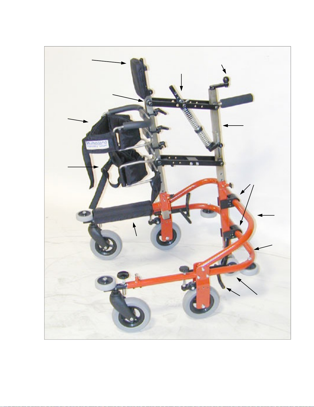
COMPONENTS
Refer to figure 1.
1. Pelvic support
2.
Trunk support
3.
Front column
4
4.
Head rest
5.
Spring stop assembly
6.
Crank
7.
Rear column
8.
Tube adjustment clamps
9.
Column brace
10.
Base frame
11.
Anti-
12.
Toggle brake
13.
Sit bar
tipper wheels
4
6
5
3
2
1
13
7
8
9
10
Figure 1
11
12
5
ASSEMBLY
Tools Required:
3/16 allen wrench (included in pouch)
5/32 allen wrench (included in pouch)
1/4 allen wrench (included in pouch)
Tape measure
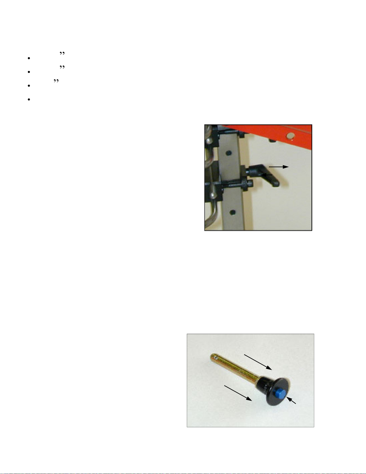
Adjustment Levers:
Refer to figure 2.
The adjustment levers can be
ratcheted so the handle can rotate
without affecting the tightness of
the screw.
1.
Pull out on black knob. Rotate the
handle so it is not obstructed.
2.
Release the black knob, and let
Figure 2
the handle slide back and lock
with the screw.
3. Continue tightening/loosening the screw by rotating the
handle.
Ball Lock Pins:
Refer to figure 3.
1. Hold the head of the pin
between your index and
middle fingers.
2.
Press in on the button (1) with
6
your thumb while extracting
or inserting the pin.
Figure 3
1
Assembly Instructions:
Column Adjustment Tube:
Refer to figure 4
1.
Place the base assembly on the floor.
2.
Loosen the four allen screws on the
tube adjustment clamps (1).
3.
Slide the column adjustment tube (2)
through the tube clamps.
4.
Tighten all four allen screws on the
tube clamps.
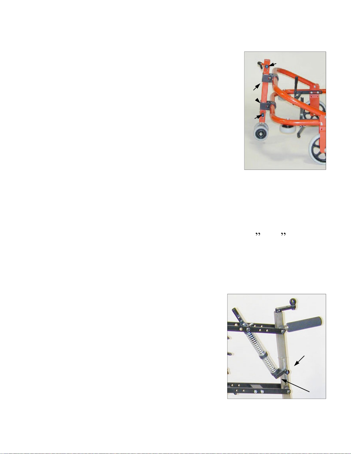
Anti-
Tipper:
2
1
3
Figure 4
Refer to figure 4
1.
Remove the ball lock pin (3) from the column
adjustment tube.
2.
Adjust the anti
the ground
Spring Stop Assembly:
Refer to figure 5
1. Remove the ball lock pin (1) and
attach the bottom end of the spring
stop assembly (2).
2. Reinsert the ball lock pin, to secure
it into place.
-tipper wheels so they are 1 to 2 from
1
1
Figure 5
2
7

Column:
Refer to figure 6
1.
Loosen the T-nut (1) and
remove the ball lock pin
(2).
2.
Slide the rear column into
the column adjustment
tube.
3. Replace the ball lock pin
and tighten the T
-nut to
lock the column assembly
in place. (Keep reading
for further instructions on
fine tuning.)
1
2
Figure 6
Completed
Assembly:
Refer to figure 7
8
Figure 7
 Loading...