

Mulholland ROCKET User Manual
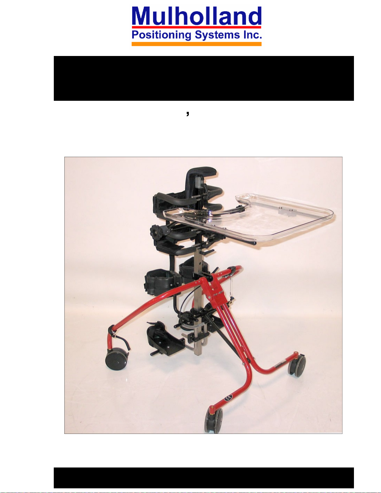
ROCKET STANDER 1 & 2
User s Manual
1

TABLE OF CONTENTS
Preface
Design Goals
Precautions
Components
Assembly
Adjustment Overview
Fitting Instructions 10
Main Column Adjustment
Tray Adjustment
Knee Block Adjustment
Foot Support Adjustment
Folding the Stander
3
3
3
4
5-8
9
10-11
12
13
14
15
Optional Configurations 16-21
Supine Stander
Neckrest Support System (Prone)
Shoulder Pad Assembly
Placing the Child in the Stander
Maintenance
Technical Data
16-17
18-19
20-21
22
22
23
2

PREFACE
This instruction manual provides information to professionals for the set
up and use of the Rocket Stander. Supported standing can stimulate head
righting, weight-bearing on the forearms, and mid-line hand use. Standing
also provides an opportunity for peer socialization and upper extremity
activities, which should be an integral part of a standing program.
DESIGN GOALS
The Rocket Stander was designed to provide individuals requiring prone,
vertical, or supine standing, precise postural control at the upper trunk,
pelvis, knees, and ankles. Adjustment from prone to vertical to supine
offers therapists the opportunity to provide graduated weight
promote more normal tone distribution and stability, and selective
extension of the spine.
-bearing to
-
PRECAUTIONS
1. Standing should always be prescribed by the child s physician with
recommendations for duration of standing, frequency and
contraindications. The standing program should be closely monitored
by the child s therapist.
2. The stander should be used under direct adult supervision at all times.
3. Do not use for transportation.
4. Use stander only on level surfaces.
5. Observe load limits on product label.
3
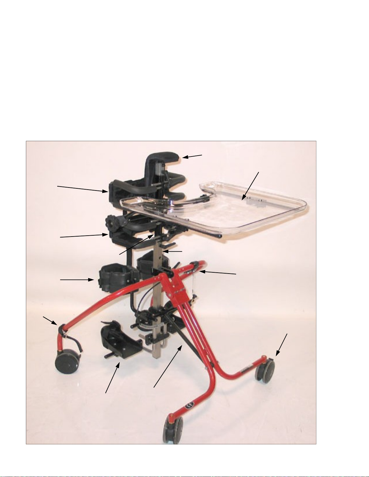
COMPONENTS
Refer to figure 1.
1.
Sternum Pad
2.
Tray Assembly
3.
Main Column
4.
Tilt Trigger
5.
Locking Castors
6.
Tilt Bar
12
7.
Shoe/Foot Supports
8.
Folding Strap
9. Knee Support
10.
Upper Column
11.
Hip Support
12.
Trunk Support
1
2
8
11
9
10
6
7
3
4
5
4
Figure 1
ASSEMBLY
Tools Required:
5/32 , 3/16 , 1/4 allen wrenches (included in the pouch)
Tape measure
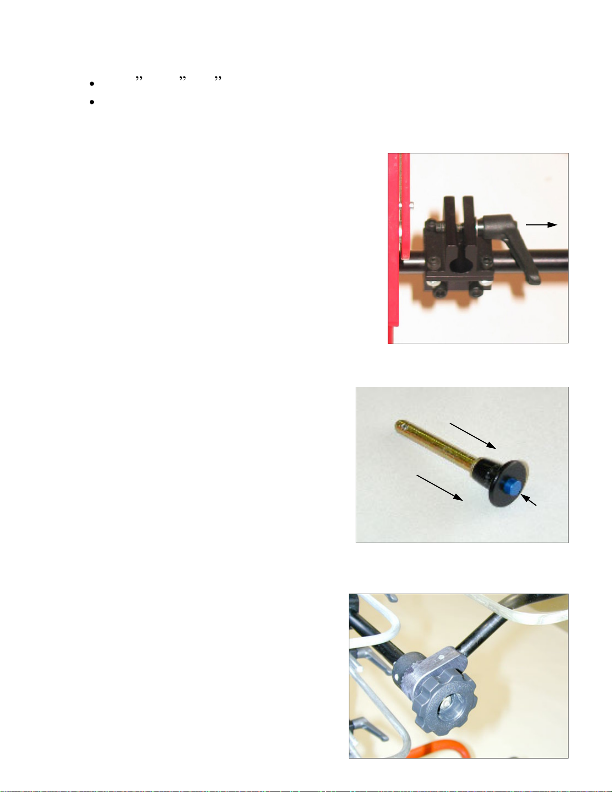
Adjustment Levers:
Refer to figure 2.
The adjustment levers can be ratcheted so the
handle can rotate without affecting the
tightness of the screw.
1.
Pull up lever to disengage.
2.
Rotate the handle so it is not obstructed.
3. Release and let the handle slide back and
lock with the screw.
4.
Continue tightening/loosening the screw
by rotating the handle and repeating steps
1-
3 as needed.
Figure 2
Ball Lock Pins:
Refer to figure 3.
1. Hold the head of the pin between your
index and middle finger.
2. Press in on the blue button with your
thumb while extracting (or inserting)
the pin.
Hand Knobs:
Refer to figure 4.
1. Release (unlock) the knob by turning
it counter-clockwise.
2.
Lock the knob by turning it clock
-
Figure 3
1
wise.
Figure 4
5
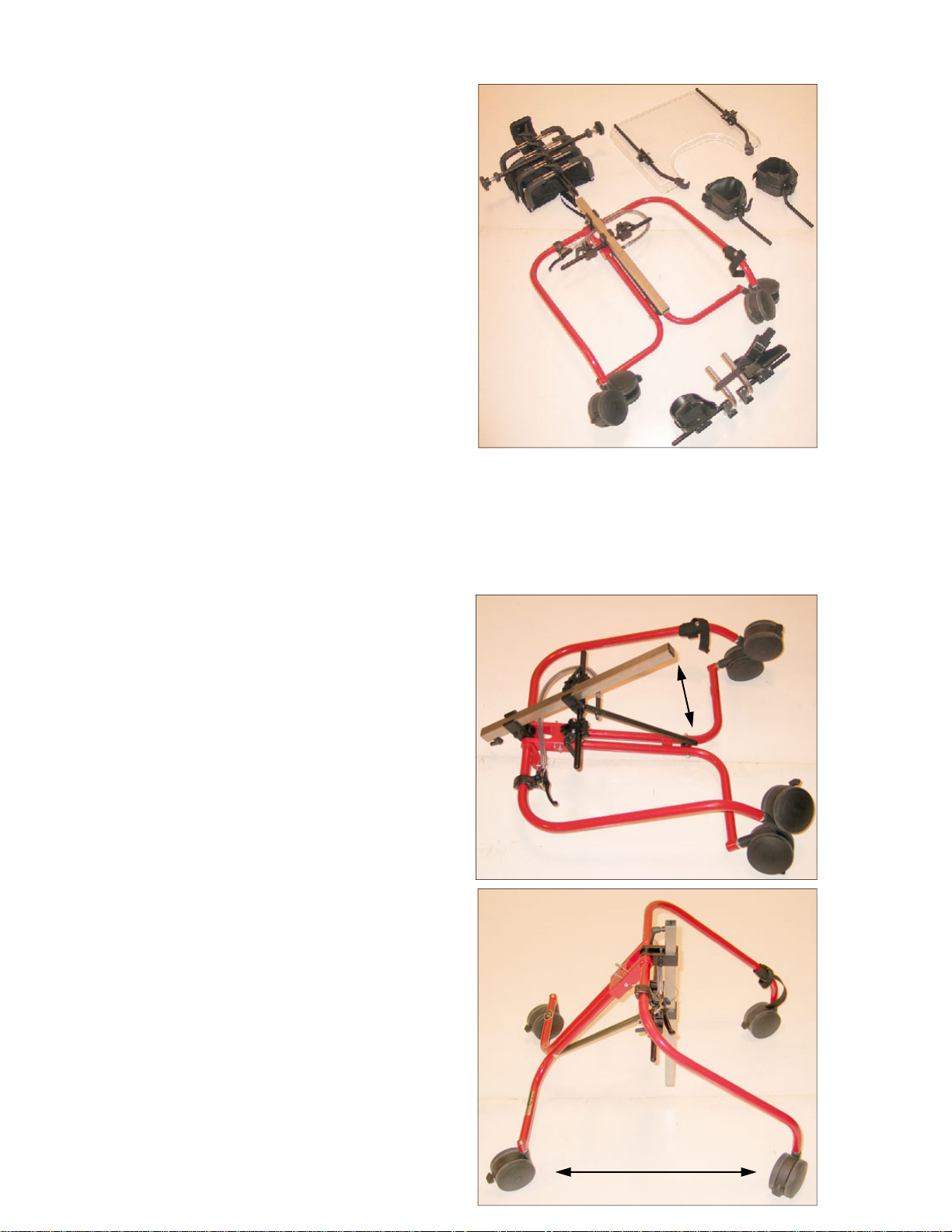
Step A: Prepare for Assembly
Refer to figure 5.
Lay the components out on the floor.
You should have received the following
for a basic system:
1.
Base
2.
Upper Column
3.
Tray
4.
Two Knee Supports
5.
Foot Support
Figure 5
Figure 7
C2
C1
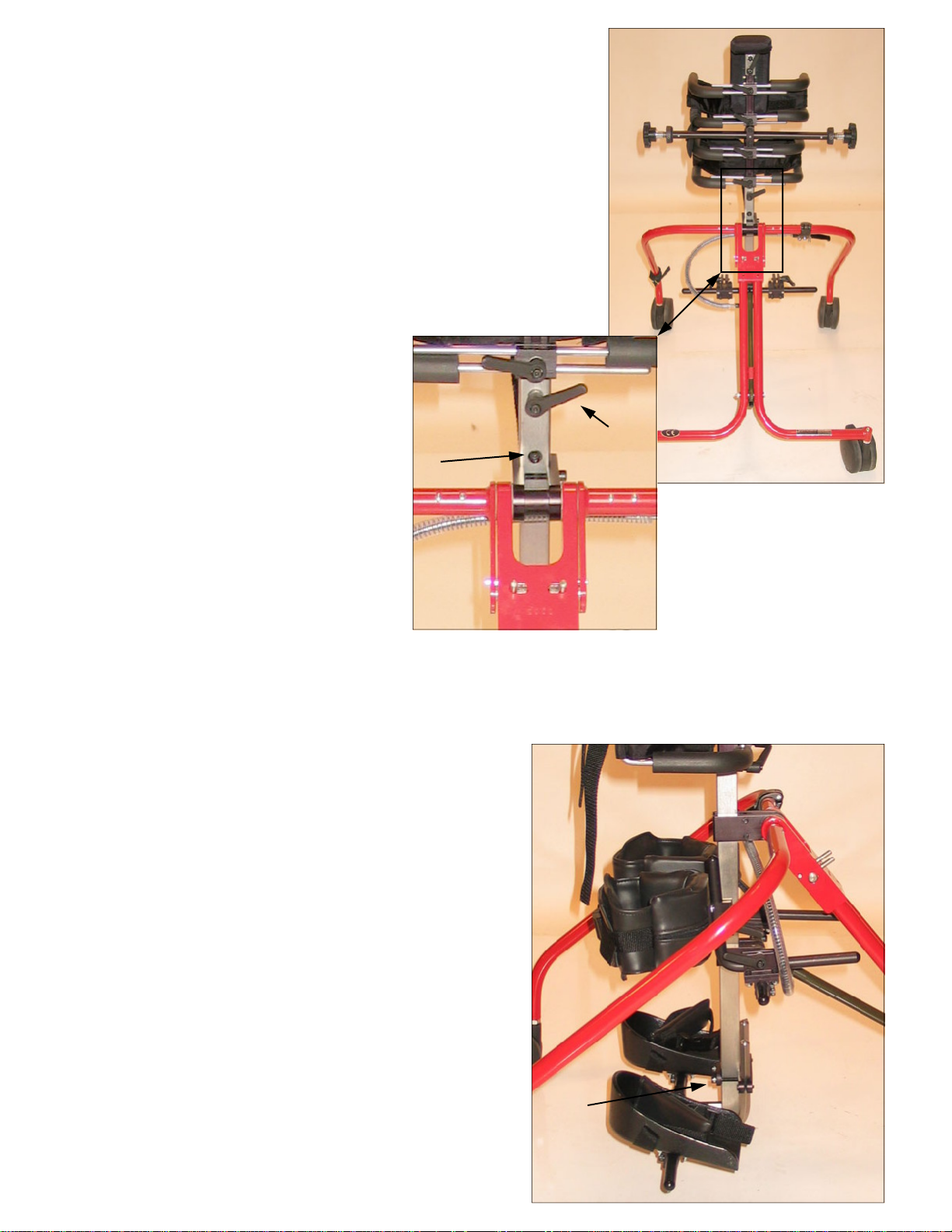
Step B:
Refer to figures 6 & 7.
1. Pull up on the main column until the
tilt mechanism slides in between the
black markings.
2.
Tighten the two allen screws that
secure the tilt bar to the main
column.
3.
Swing the legs away from each other
until they lock into place.
Note: The main column is correctly
aligned if it is vertical when the base is
standing on the floor.
Assembly the Base
Figure 6
Figure 7
6
Step C: Insert the Upper Column
Refer to figure 8
1.
Remove the allen screw from the bottom
part of the upper column.
2.
Slide the upper column down into the main
column.
3.
Line up the holes in the upper and main
columns (1), and tighten the adjustment
lever to secure.
4.
Insert the allen screw
(1) and tighten.
1
2
Figure 8
Step D: Attaching the Knee Blocks
and Foot Supports
Refer to figure 9.
1.
Slide the Knee Blocks into their
respective brackets and secure with
the adjustment levers. The vertical
adjustment levers should be facing
outward.
2.
Slide the foot supports onto the
bottom of the column, and secure
by tightening the two allen screws
(1).
1
Figure 9
7
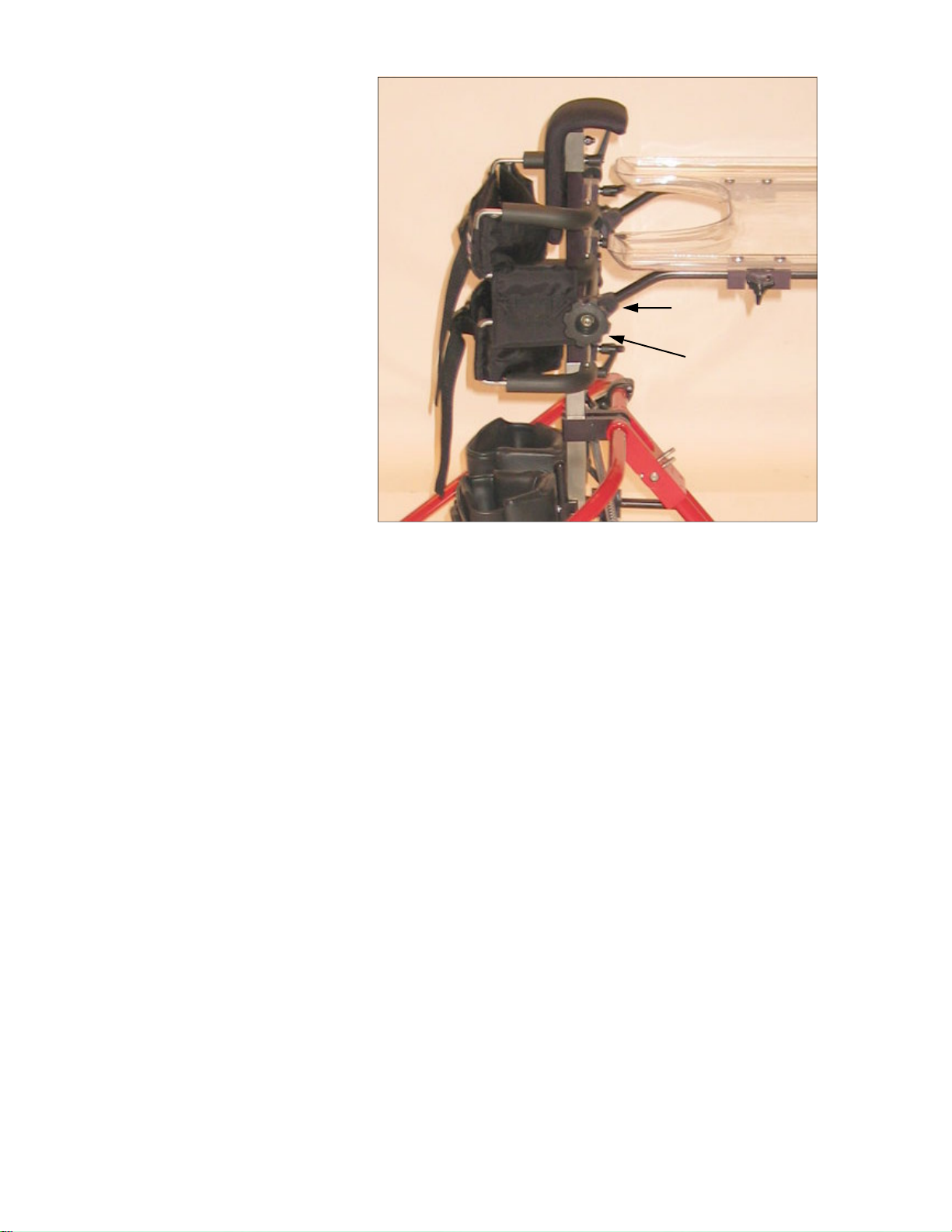
Step E: Attaching the tray
Refer to figure 10.
1. Release the hand knobs (1)
on the ends of the tray
mounting bar.
2.
Place the tray assembly on
the tray mounting bar so
the teeth on the angle locks
(2) mesh.
3.
Lock the cams to secure
the tray by turning the
hand knobs (1) clockwise
until tight.
Figure 10
2
1
8
 Loading...