

Mulholland PEER LEVEL SUPINE ASSEMBLY User Manual
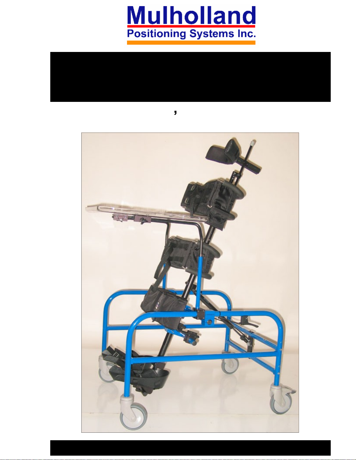
PEER LEVEL STANDER
SUPINE ASSEMBLY
User s Manual
TM
1

TABLE OF CONTENT
S
Preface
Precautions
Required Tools
Components
Assembly
Trouble Shooting
Fitting Instructions 10
Adjustment Overview
Adjustments
Options: Supine Neckrest and/or Shoulder Pads
3
3
4
4
5-9
10
12-15
16-17
11
Placing the Child in the Stander
Maintenance
19
18
2

PREFACE:
These pages provide information to professionals for the
set up and use of the Supine Assembly version of the Peer
Level Stander. The Mulholland Standing Systems are
designed to provide individuals requiring prone, vertical,
or supine standing, precise postural control at the upper
trunk, pelvis, knees and ankles. All standers adjust from
prone to vertical to offer therapists the opportunity to
provide graduated weight-bearing to promote more normal
tone distribution and stability, and selective extension of
the spine. Standers also stimulate head-righting, weight
bearing on the forearms and mid-line hand use. Standing
provides an additional opportunity for peer socialization
and interaction, and upper extremity activities should be an
integral part of the standing program.
PRECAUTIONS:
Standing should always be prescribed by the child's
physician with recommendations for the duration,
frequency, and contraindications.The standing program
should be closely monitored by the child's therapist.
-
USE
OF THE STANDER SHOULD BE UNDER DIRECT
ADULT SUPERVISION AT ALL TIMES.
3

REQUIRED TOOLS:
Tape Measure
Allen Wrenches (3/16 , 5/32 ) (Included in tool pouch)
COMPONENTS:
Refer to Figure 1.
1.
Hip Support
2.
Trunk Support
3.
Strut
4.
Column
5.
Side Frames
6.
7.
8.
9.
10.
Trigger Release
Frame Brace
Column Pivot
Foot Support
Knee Blocks
1
10
2
4
5
3
6
8
4
9
Figure 1
7

SUPINE ASSEMBLY INSTRUCTIONS:
1. Attach the column pivot
into the blocks (a) on the
top of the side frames.
Make sure the strut
receiver (b) is facing the
towards the trigger (c)
when it is above the
pivot.
a
b
c
3. Attach the frame
brace to the two side
frames, using the
lower set of holes.
Make sure the bar
with the stickers is
2. Tighten the four bolts on the
top of each side, and make sure
the block is situated so the pivot
bar is below the frame.
on top.
5
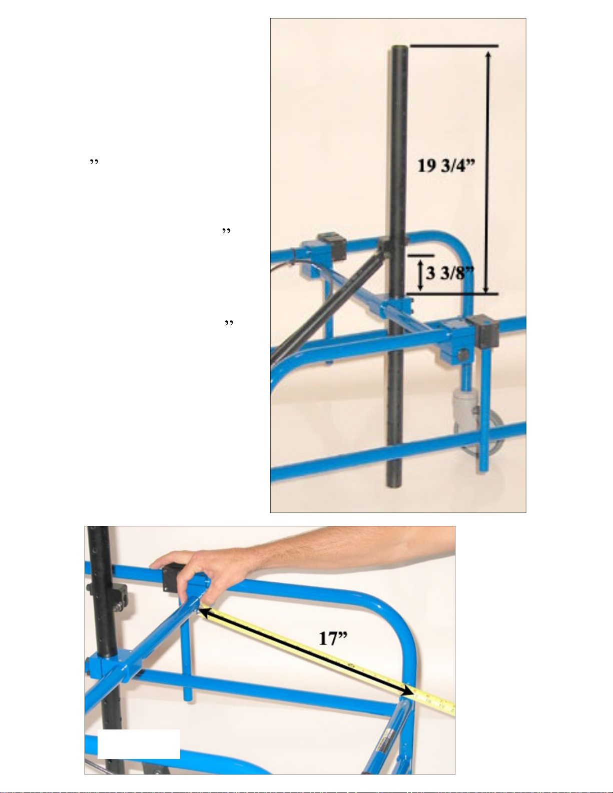
4. Three important
measurements to insure
the column is properly
positioned on the frame
are the following: 19
3/4 from the top of the
pivot clamp to the top
of the main column
piece (fig 5a); 3 3/8
from the top of the
pivot clamp to the
bottom of the strut
receiver (fig 5b); 17
on a diagonal from the
front of the pivot bar to
the back end of the top
cross brace (fig 6a).
a
b
6
Figure 6
Figure 5
a
 Loading...