

Mulholland OMNI 1, OMNI 2 User Manual
TM
User s Manual
1

TABLE OF CONTENTS
Preface
Design Goals
Precautions
Components
Assembly
Adjustment Overview
Fitting Instructions 13
Main Column Adjustment
Tray Adjustment
Knee Block Adjustment
Foot Support Adjustment
Optional Configurations 19-25
3
3
3
4-5
6-11
12
14-15
16
17
18
Prone Stander
Supine Stander
Neckrest Support System (Prone)
Shoulder Pad Assembly
Placing the Child in the Stander
Maintenance
Technical Data
19
20-21
24-25
26
26
27
22-23
2

PREFACE
This booklet provides information for the set up and use of the
Supported standing can stimulate head-righting, weight-bearing on the
forearms, and midfor peer socialization and interaction, and upper extremity activities,
which should be an integral part of a standing program.
DESIGN GOALS
The
OMNI
vertical, or supine standing, precise postural control at the upper trunk,
pelvis, knees, and ankles. Adjustment from prone to vertical to supine
offers therapists the opportunity to provide graduated weight
promote more normal tone distribution and stability, and selective
extension of the spine.
TM
line hand use. Standing also provides an opportunity
was designed to provide individuals requiring prone,
OMNITM.
-bearing to
PRECAUTIONS
1. Standing should always be prescribed by the child s physician with
recommendations for duration of standing, frequency and
contraindications. The standing program should be closely monitored
by the child s therapist.
2. The stander should be used under direct adult supervision at all times.
3. Do not use for transportation.
4. Use stander only on level surfaces.
5. Observe load limits on product label.
3

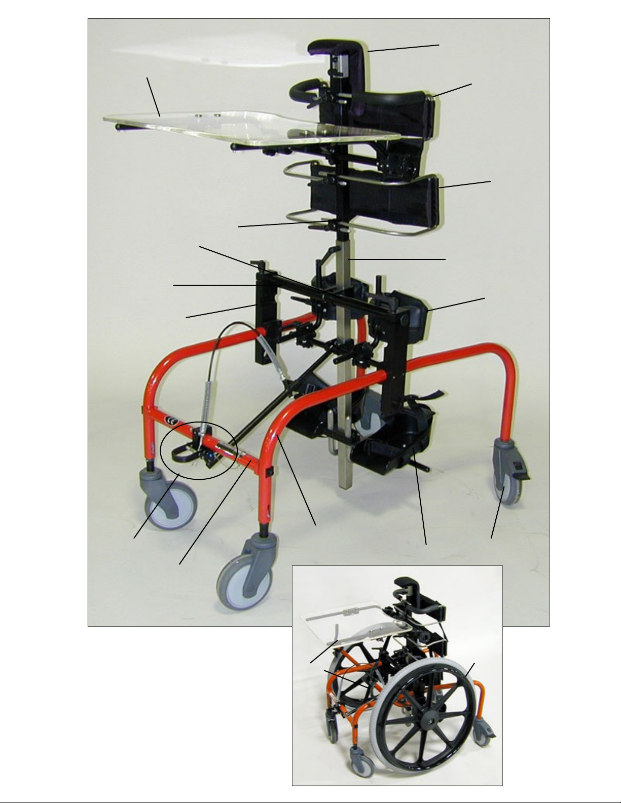
COMPONENTS
Refer to figure 1.
1.
Sternum Pad
2.
Trunk Support
3.
Tray Assembly
4.
Upper Column
5.
Hip Support
6.
Main Column
7.
Column Pivot
8.
Column Support Tube
9. Knee Support
10.
Frame Supports
11.
Side Frames
12.
Frame Brace
13.
Tilt Mechanism
14.
Shoe/Foot Supports
15.
Locking Castor
16.
Drive Wheel with Hand Rim
17.
Hand Brakes
4
3
1
2
5
4
7
6
8
9
10
13
12
Figure 1
11
14
17
15
16
5
ASSEMBLY
Tools Required:
5/32 , 3/16 , 1/4 allen wrenches
Tape measure
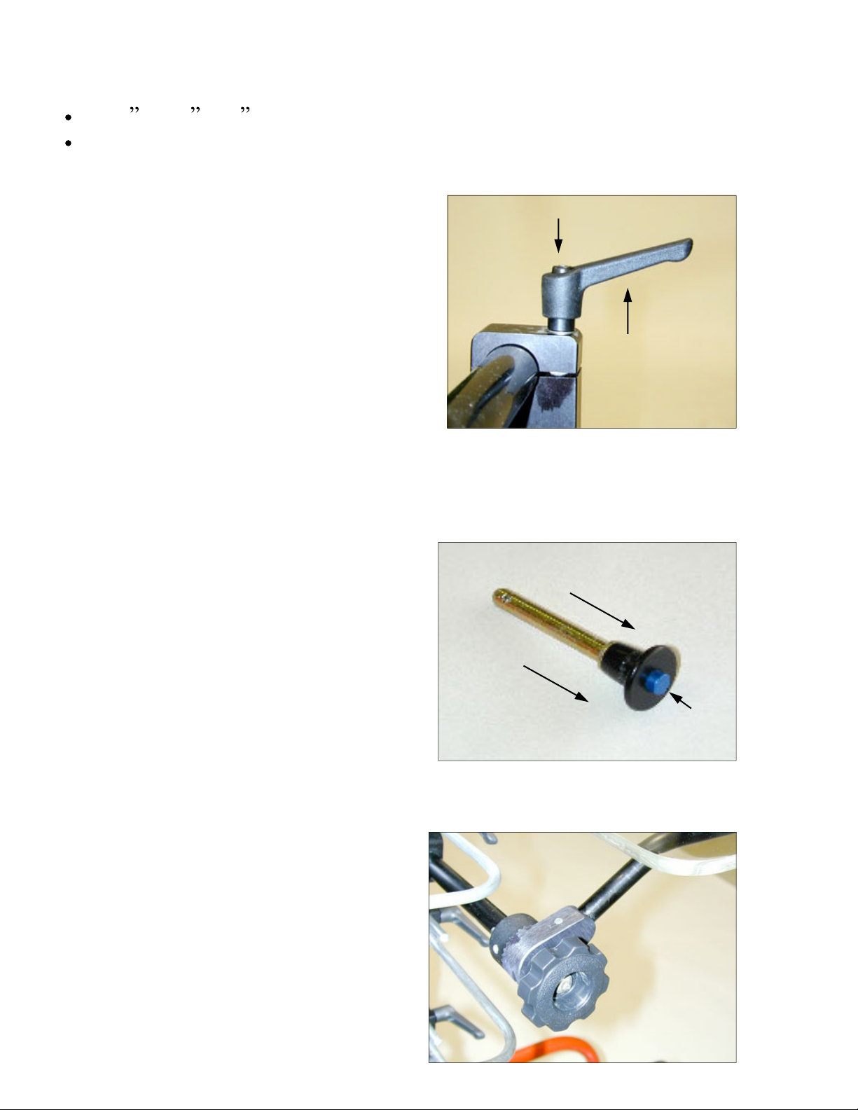
Adjustment Levers:
Refer to figure 2.
The adjustment levers can be ratcheted so
the handle can rotate without affecting the
tightness of the screw.
1.
Pull up lever to disengage.
2.
Rotate the handle so it is not
obstructed.
3.
Release and let the handle slide back
and lock with the screw.
4.
Continue tightening/loosening the screw by rotating the handle and
repeating steps 1-3 as needed.
Figure 2
Ball Lock Pins:
Refer to figure 3.
1. Hold the head of the pin between your
index and middle finger.
2. Press in on the blue button with your
thumb while extracting (or inserting)
the pin.
Hand Knobs:
Refer to figure 4.
1. Release (unlock) the knob by turning
it counter-clockwise.
2.
Lock the knob by turning it clock
-
Figure 3
1
6
wise.
Figure 4
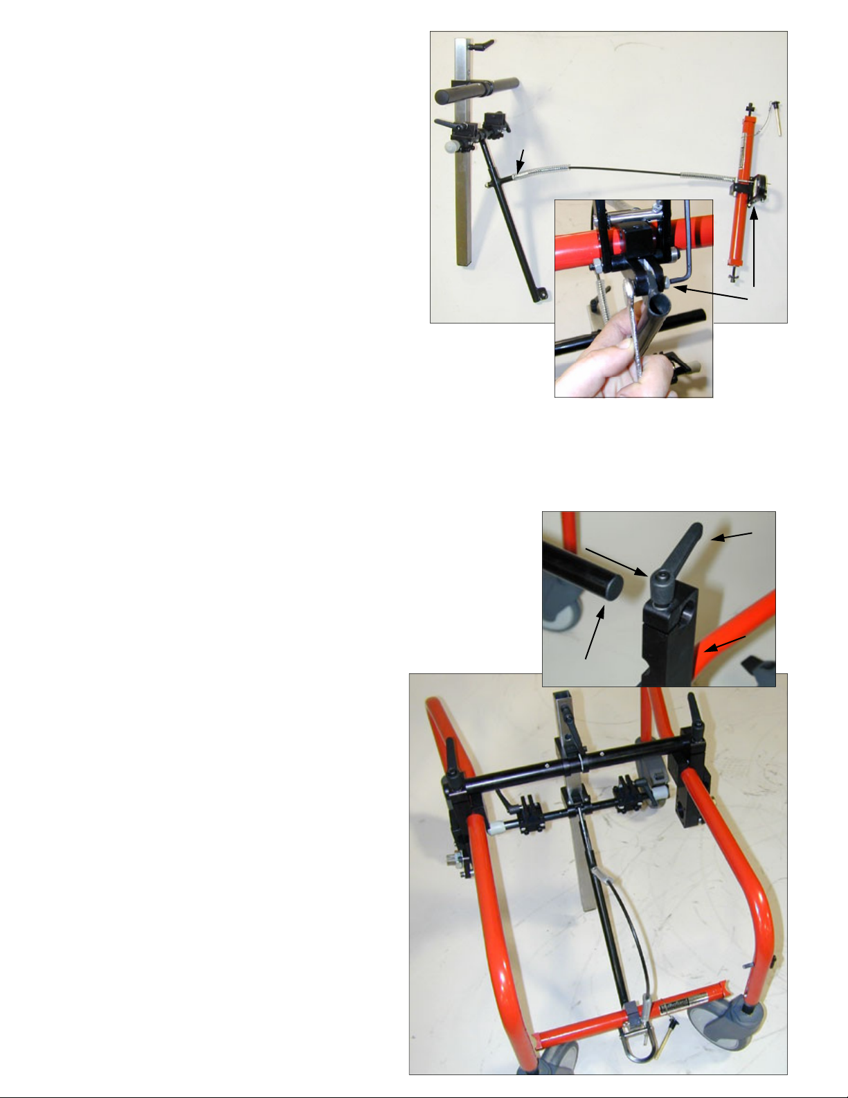
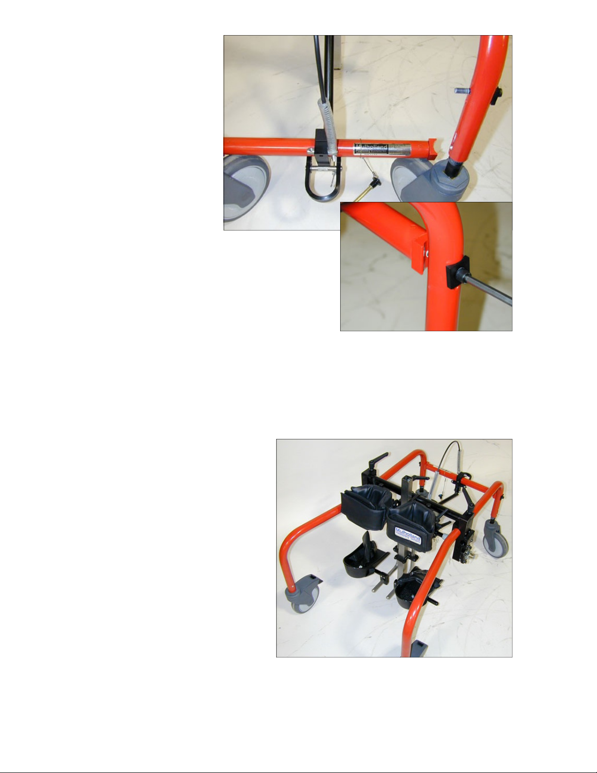
Step A: Connect the cable
Refer to figure 5.
1.
Screw the free end of the cable
into the tilt bar (1) by turning
the cable. Once the cable end
has been full screwed in,
tighten the ring bolt (1) to
secure.
2. Attach the base of the tilt bar
to the frame brace. Tighten
bolt.
Step B: Connect the side frames to the column
1
Figure 5
2
Refer to figure 6.
1.
Loosen adjustment levers (1), on the top of
the frame supports (2) .
2.
Orientation: The knee block assembly and
locking castors should both be at the rear of
the OMNI.
3.
Slide the top holes of the frame supports
onto the ends of the column
support tube (3).
4.
Slightly tighten the
adjustment levers so the
width can be adjusted during
step C.
Figure 6
1
2
3
7
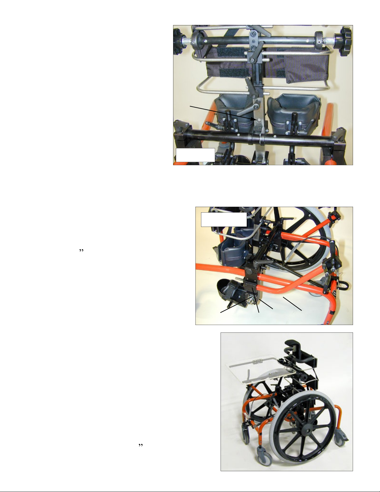
Step C: Attach the Frame Brace to the Side Frames
Refer to figure 7.
1.
Remove the hex head
screws (1) and the
washers from the ends of
the frame brace.
2.
Position the frame brace
between the side frames
so the side frames fit
within the curve of the
end fittings and the holes
align.
Figure 7
3.
Insert a screw with a
washer through the aligned holes of the
side frame and frame brace. Tighten secure
the frame brace, ensure the side frame is
seated snuggly within the end fitting.
C2
C1
Figure 7
Repeat for both sides.
4.
Straighten the frame (if necessary) then tighten the two adjustment
levers (1 Fig 6.) on the top of the frame supports.
Step D:
Refer to figure 8.
1.
Slide the Knee Blocks into their
Attaching the Knee Blocks and Foot Supports
respective brackets and secure
with the adjustment levers.
2.
Slide the foot supports onto the
bottom of the column, and secure
by tightening the two allen
screws.
Step E: Attaching the Upper Column
8
Figure 8
Refer to figure 9.
1.
Remove the allen screw
from the bottom part of
the upper column.
2.
Slide the upper column
down into the lower
column.
3.
Line up the holes in the
upper and lower columns
(1).
4. Insert the allen screw (1)
and tighten.
Step F: Adding the Mobility Kit
Refer to figure 10 (steps 1-3) and figure
11 (steps 4-10).
1.
Attach the brake clamp (1) to
1
Figure 9
Figure 10
the frame support with four
3/4 allen screws (2) so a
circular opening is formed. Do
not tighten the screws
completely (it may already be
attached).
2.
Slide the brake tube (3) through
the hole created by the frame
support and brake clamp.
Tighten the allen screws.
3. Repeat steps 1 & 2 for both the left
and right side frames.
4. Wheel mounting plate orientation:
Attach the wheel plate (4) to the
outside face of the frame support. If
these are already attached, skip to
2
Figure 11
1
4
3
step 9.
5.
Attach the upper edge of the wheel
plate with two 7/8 allen screws.
Insert a washer through each of the
screws between the screw head and
9
 Loading...