

Mulholland GAIT MASTER User Manual
GAIT MASTER II
User s Manual
TM
ADULT
1

TABLE OF CONTENTS
Preface
Design Goals
Components
Precautions
Assembly
General Information
Assembly Instructions
Fitting Instructions
Measuring The User
Preparing The Unit
Options
3
3
4
6
7
7
14
14
15
22
9
Gas & Coil Springs
Abduction Seat
Front Caster Anti-Swivel Lock & No-Backs
Head, Neck, & Shoulder Support
Seat Support Frame Only
Pelvic Support
Getting In & Out
Assisted Entry
Unassisted Entry 24
Assisted Exit
Unassisted Exit 31
23
24
24
24
31
22
23
23
23
2
Fine Tuning
Spring LockCollapse & Transportation
Technical Data
Maintenance
34
Out
36
40
41
36

READ ENTIRE MANUAL B
EFORE USE!
PREFACE
This booklet provides information to professionals for
the setup and use of the adult Gait Master . The benefits
of using the system can be profound, not only in terms of
gait development, but also in terms of increasing the user s
independence, self-confidence, and social interaction. The
Gait Master provides upper body support along with
weight relief as the user develops gait skill and tolerance.
DESIGN GOALS
The Gait Master is designed to give the user the
potential of hands-free, self-initiated movement while
providing lateral support and assisted lift. A two-part
spring assisted lift allows for dynamic weight relief
throughout the entire gait, and assists the user up to and
down from a standing position. Extreme adjustment of the
seat, thoracic, and sternum supports are possible with quick
and easy adjustments. If deemed allowable by a
professional, a user can get into, out of, and secure
themselves in the Gait Master with no outside
assistance. Additionally, adjustment of seat height and
thoracic supports are possible while the user is secured in
the unit, and the fine-tune seat height control can be easily
controlled by the user while they are in the Gait Master .
3

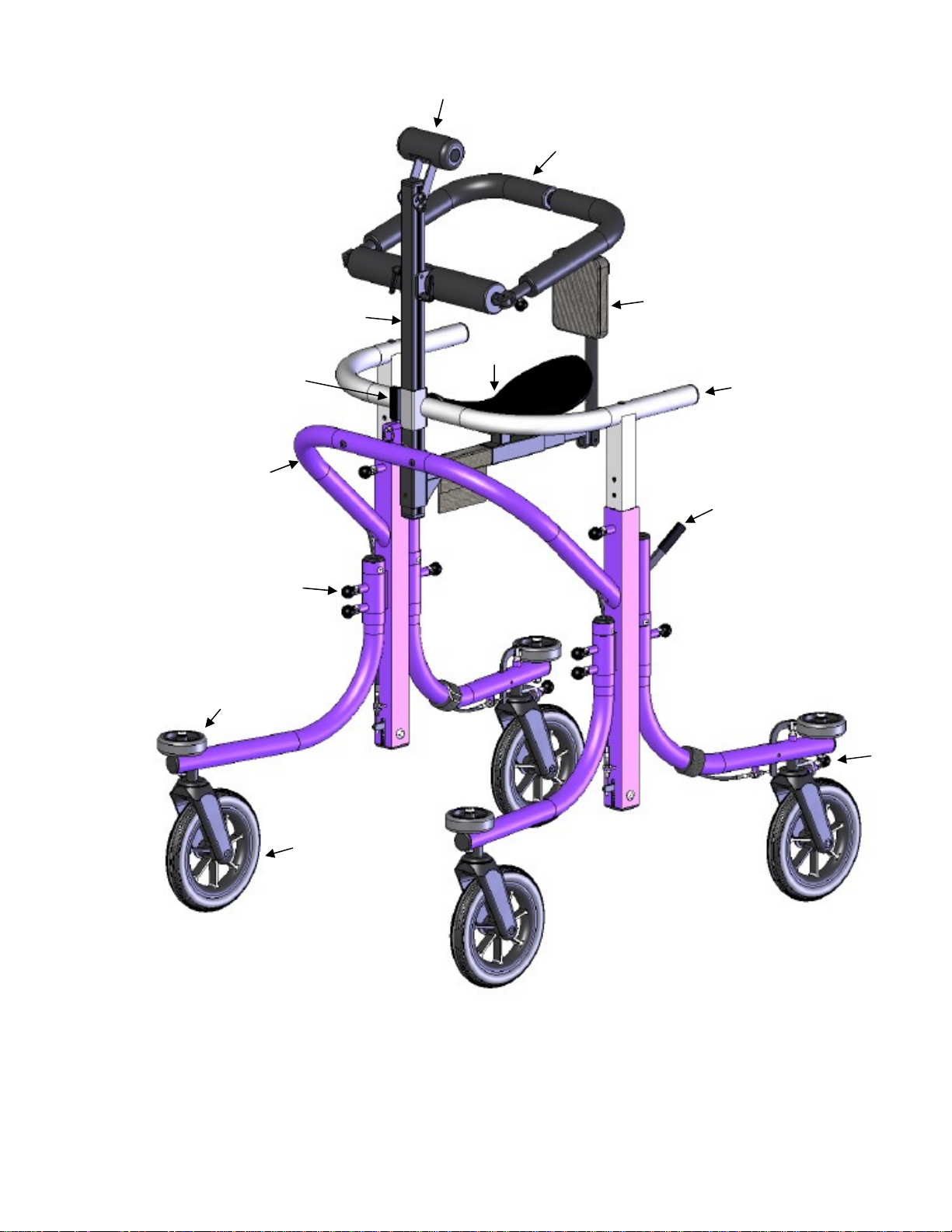
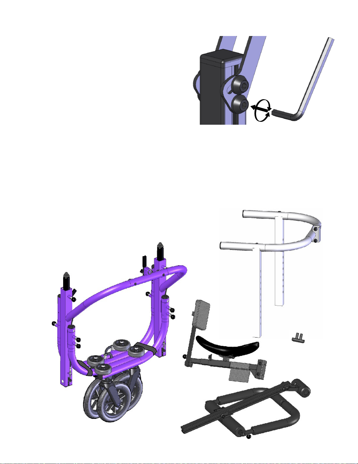
COMPONENTS
Refer to Figure 1
1.
Sternum Support
2.
Thoracic/Upper Back Support
3.
Rear Seat Pad
4.
Seat
5.
Upper Frame (silver)
6.
Brake Handle
7.
Caster Anti-Swivel Lock
8.
Caster Wheel
9.
Bumper Wheel
10. Pull Knob
11.
Lower Frame (colored)
12.
Gas Spring Height Adjustment Lever
13.
Center Vertical Column
4
13
1
2
3
4
9
11
12
10
5
6
7
Figure 1
8
5

PRECAUTIONS
1.
Standing and or gait training is only carried out under the
prescription of the user s physician along with the
recommendations for duration, frequency, and
contraindications.
2.
A therapist must always be present while the Gait
Master is in use, unless a physician and therapist have
authorized independent use of the Gait Master to the
user.
3. The Gait Master can tip over if used by a tall
individual with poor upper body control.
4.
Best if used on level surfaces, and be moved slowly up/
down handicap approved ramps only.
5. Do not use for transportation in vehicles or as a push
stroller.
6.
Check all knobs, latches, and screws that are used for
body positioning adjustments before every use to ensure
they are securely fastened.
7.
Periodically check all fasteners, and tighten any loose
fasteners. Loose fasteners can cause the Gait Master
to be inoperable.
8.
Check each of the four caster legs to check that they are
locked and cannot swivel before the user gets into the
unit.
9.
The thoracic supports and rear seat pad bar must be
locked into position at all times during use, unless the
user is getting into or out of the Gait Master .
10.
floor during use.
11.
Secure the rear leg straps so they do not drag on the
Do not put fingers or body parts in/near joint pinch
6
points or holes during operation.
ASSEMBLY
General Information
Tools Required
3/16
5/32 Allen Wrench (included in tool pouch)
Tape Measure
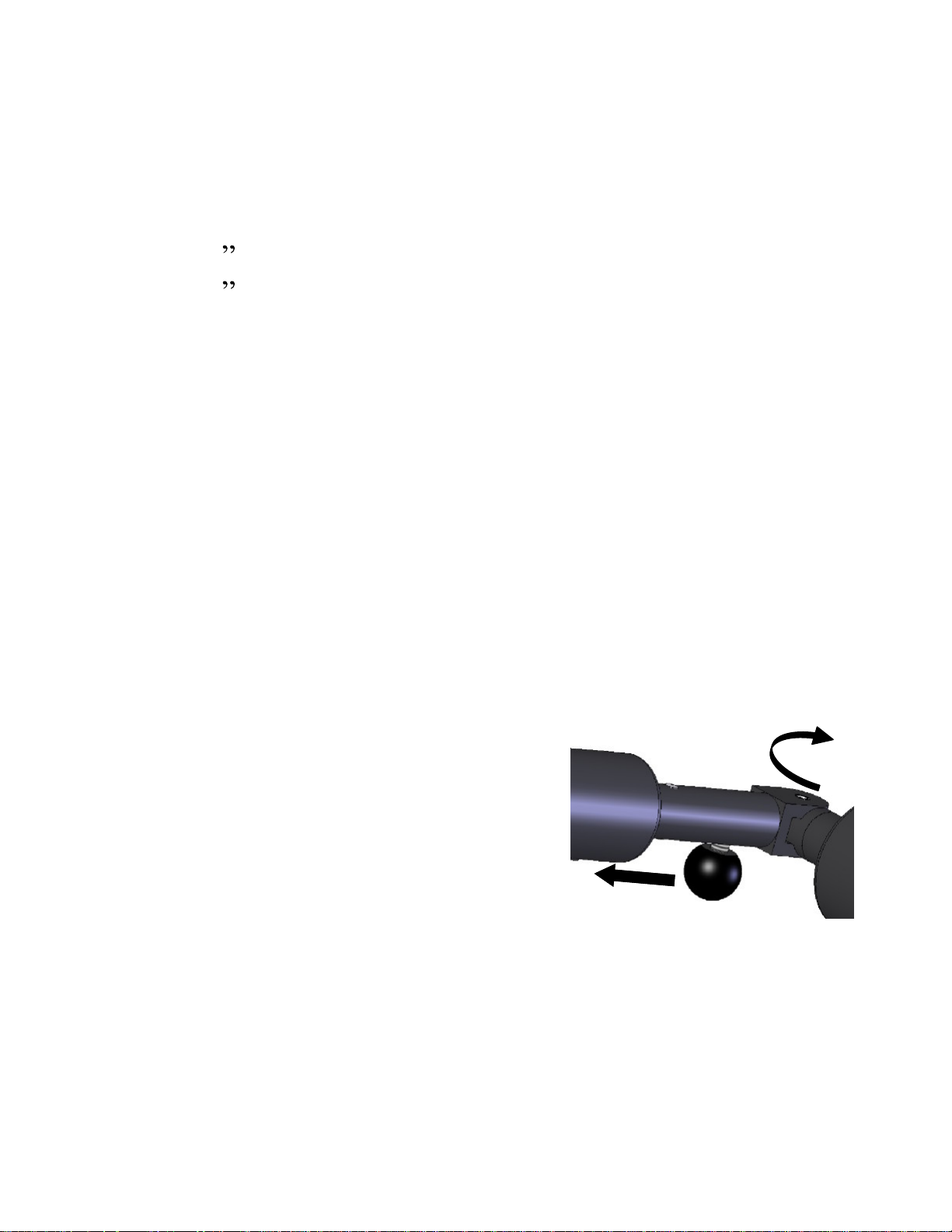
Sliding Knobs
The sliding knobs are found on the thoracic ring support,
Allen Wrench (included in tool pouch)
and the rear seat pad. These knobs slide along the length
of the tube, and automatically lock into place. Push the
round black knob along the length of the tube and away
from the hinge joint. Rotate the hinge joint outward and
release the knob. Refer to Figure 2.
To lock the knobs back in
place: swing the arm containing
the knob to its locked position.
The knob will automatically lock
into place.
Figure 2
7
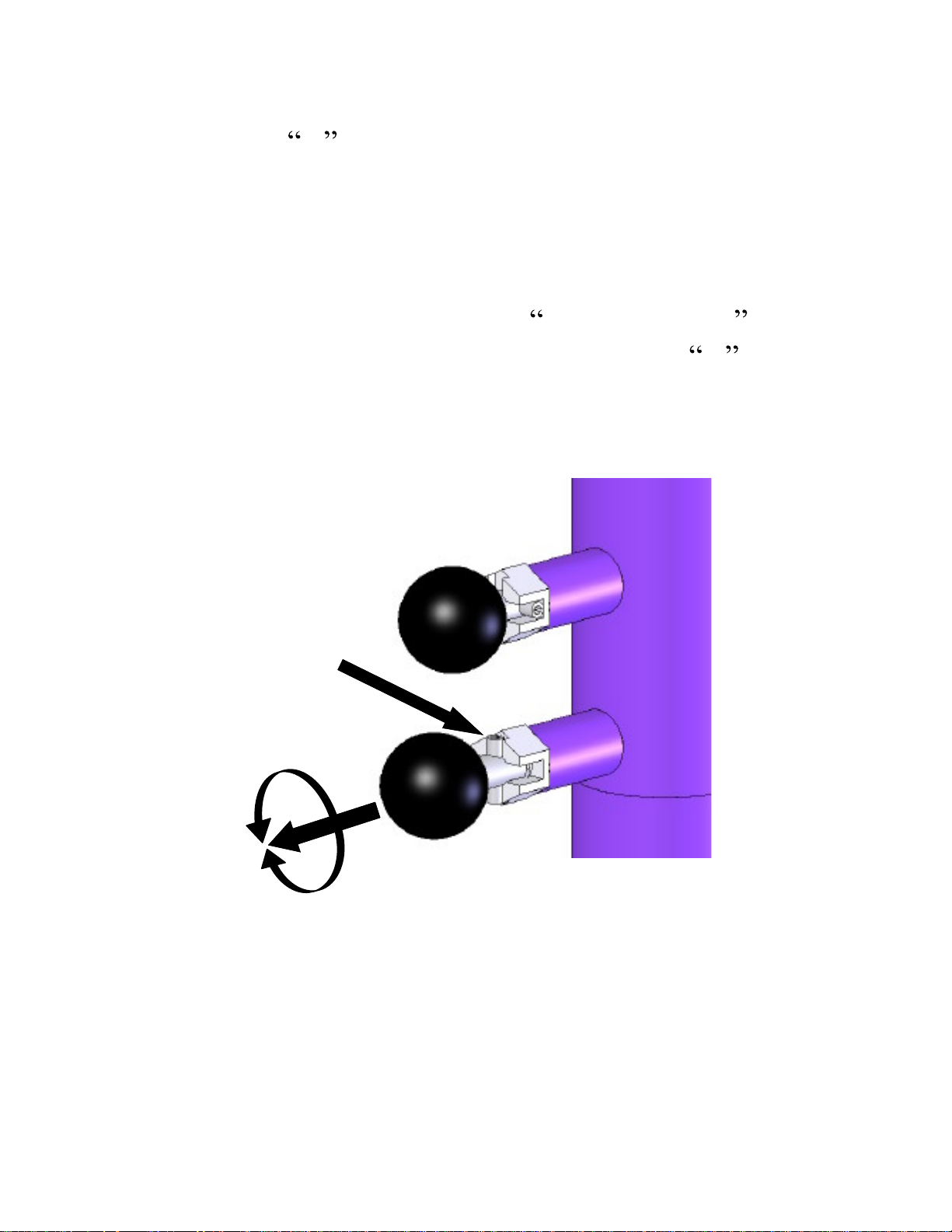
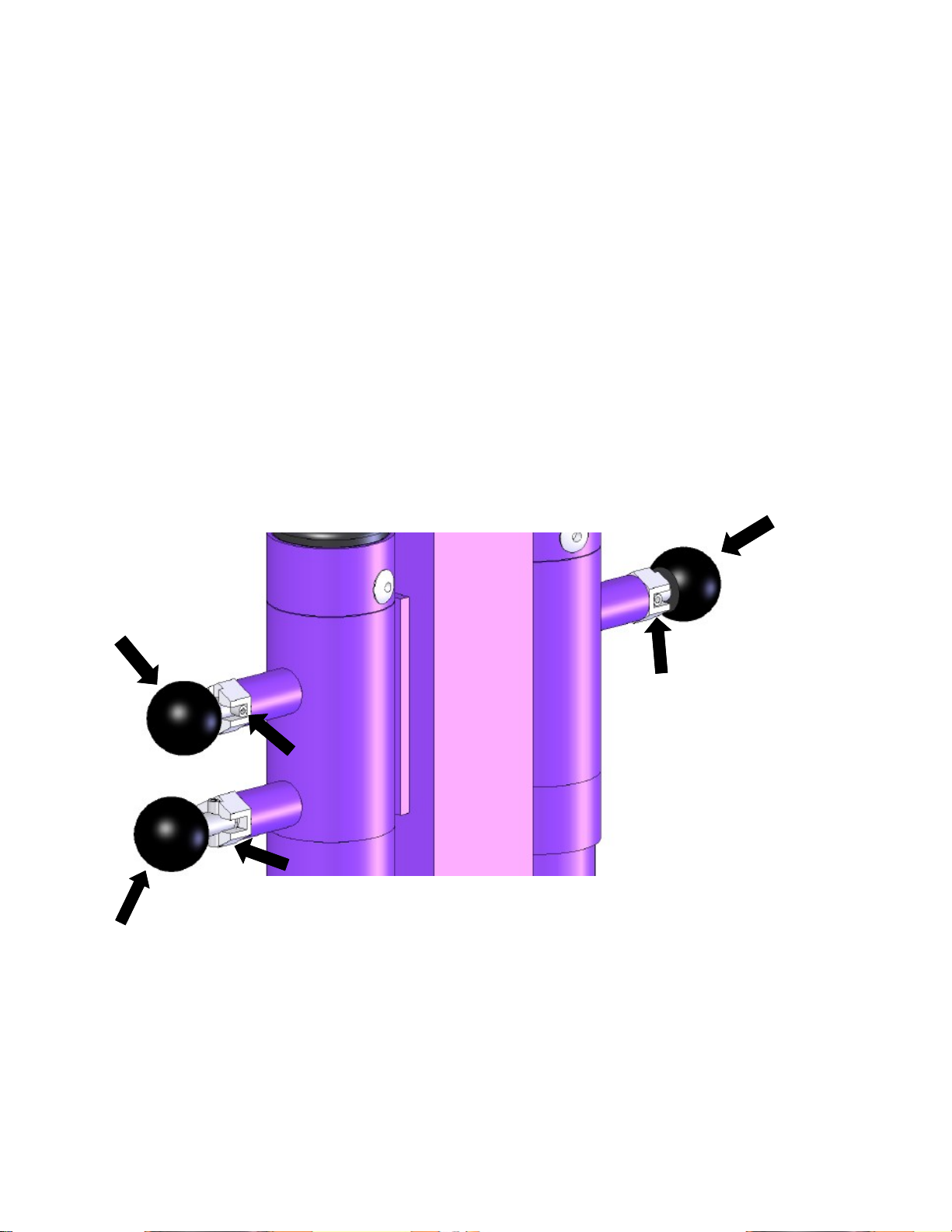
Pull Knobs
Pull knobs are found on the lower frame. Behind the
round knob is an X shaped slot. These slots act as a
guide for a retaining pin attached to the pull knob. Pull the
round black knob out so the retaining pin is free. Rotate
the knob 90 degrees so the retaining pin lines up with other
slot. Release the knob and allow the retaining pin to slide
into the slot. The pull knob is in the locked position
when the retaining pin is in the deeper of the two X slots.
Refer to Figure 3.
Retaining Pin
Locked
8
Figure 3
Unlocked
Allen Screws
All other adjustments are
comprised of allen screws.
Insert the short end of the
appropriate allen wrench into
the socket of the allen screw.
Tighten or loosen the screw
by turning the allen wrench.
Assembly Instructions
Unpack and unwrap all of the parts. Depending on your
specific order, your parts may
differ than the ones shown below.
Figure 4
Figure 5
9
Unwrap the two black straps that keep the caster legs
together, and rotate the legs to an open position as shown
in Figure 1. The caster legs do not automatically lock into
place. Put away the straps by wrapping them around the
leg and looping the strap through the two D-rings.
Lock the caster legs in place. Rotate the rear leg pull
knobs so the retaining pin is aligned with the deepest slot.
Release the knob. It is ok if the knob does not slide all the
way into the slot. Rotate the caster leg back and fourth
until the retaining pin locks the leg in place. Refer to
Figure 6, note that the location of the slots may not be as
depicted as in the figure.
10-
Deg. Knob
Locked
Unlocked
Rear Knob
Locked
10
18-
Deg. Knob
The front caster legs have two locking pins each. One to
lock the leg at a 10-degree angle, and the other to lock the
leg at an 18-degree angle. It is suggested to start with the
front legs at the 18-degree outward angle for first time
users, for use on outside/uneven terrain, or individuals
requiring added stability.
Figure 6
When changing between the 10 and 18-degree angles for
the front leg, make sure both knobs on the front leg are in
the unlocked position before rotating the leg. It is only
required to lock the knob that relates to the desired leg
angle position.
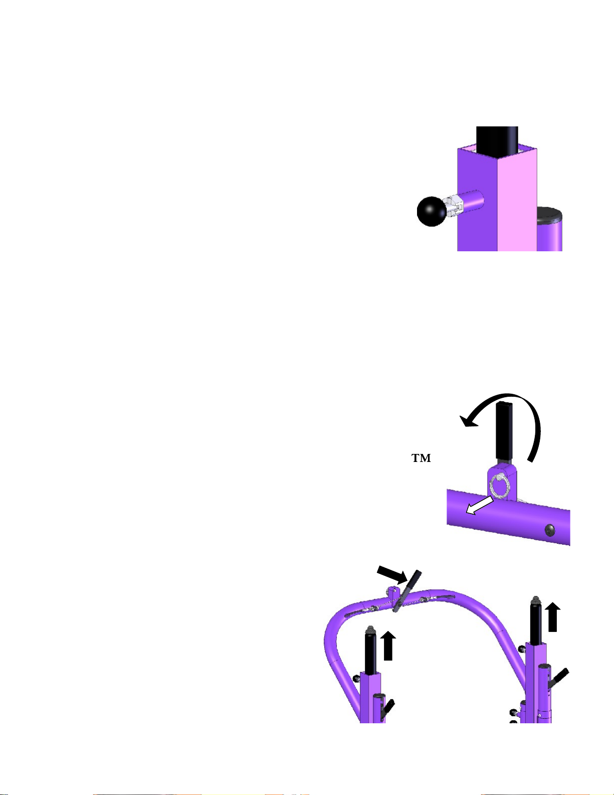
If the silver and colored frames are not
together: Confirm that the pull knobs
near the top of the square tubes are in
the unlocked position (retaining pin is
in the shallow slot) as shown in Figure
7. If they are in the locked position, the
upper frame will not slide into the lower frame.
Actuate the gas springs* to make insertion of the upper
frame into the lower frame easier (This may already be
done for you before the unit was packaged).
Figure 7
Pull the ring toward the front of the unit
while rotating the gas spring release lever
toward the right side of the Gait Master .
Refer to Figure 8. The ring may by
released once the handle is vertical.
Continue to rotate the handle until both gas
springs stop rising out of the square tubes.
*Caution,
will extend upward out of
the opening of the square
tubes (Figure 9), and can do
so with much force and
the gas springs
Pull
Figure 8
speed. Keep clear of the
opening of the square tubes
while actuating the gas spring release handle.
Figure 9
11
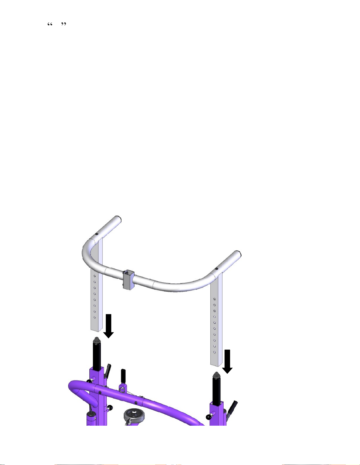
Insert the upper frame into the lower frame. Make sure
the U shape of the silver round tube is pointing toward
the front of the lower frame. Insert the silver vertical
square tube over the black round gas spring. Refer to
Figure 10. Continue to slide the upper frame down and
into the square tube of the lower frame. Fixed inside the
larger square tube of the lower frame are plastic inserts.
These pieces fit snugly between the two square tubes. If
the silver square tube does not immediately slide past the
plastic inserts, put slight pressure on the silver square tube
to help align it in place. When aligned properly, the upper
frame should easily slide down into the lower frame.
Forcing the upper frame into the lower frame when not
properly aligned can cause damage to the plastic inserts.
12
Figure 10
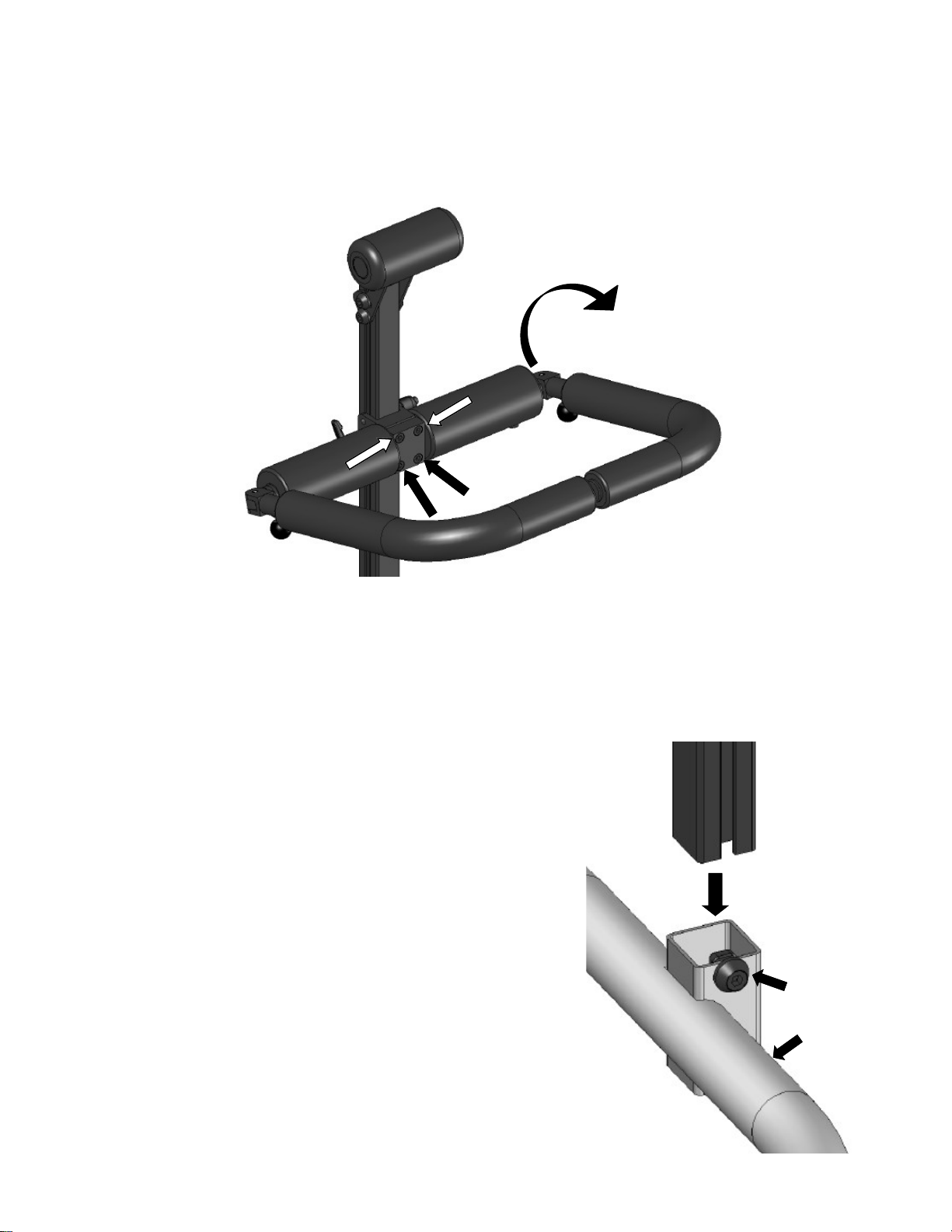
Rotate the thoracic support so the front pads are about 4
inches (10 cm) lower than the rear curved pads. Loosen
the four allen screws on the central block, only one or two
turns is necessary. Rotate the support arms and tighten all
four allen screws firmly.
Screws
Rotate
Figure 11
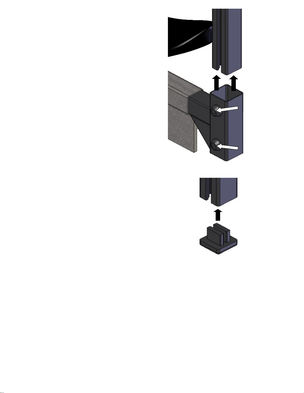
Insert the center vertical column into the top of the
square opening in the center of the upper frame. Remove
the end-cap from the column. Slide the center vertical
column into the square opening.
Make sure that the nuts attached to
the screws can slide into the
groove of the vertical column. It
may be necessary to rotate the
screws a few turns to line up the
nuts correctly. Slide the center
column toward the floor until
about 5 inches (13 cm) extends
below the square opening. Firmly
Screws
tighten both of the screws located
on the side of the square tube until
the column is securely in place.
Figure 12
13
Attach the seat to the center
vertical column. Slide the open
square tube attached to the seat
frame up around the center vertical
column. Make sure the nuts
attached to the allen screws are
aligned so they can slide into the
groove of the center column. Stop
when about a 1/2 inch (1.5 cm) of
the column extends below the
square tube. Firmly tighten the
allen screws until the seat is
securely in place.
Attach the end cap of the center
column. Push the cap into place until it
cannot go any further.
FITTING INSTRUCTIONS
Measuring The User
Figure 13
Figure 14
14
#1: Inseam + 2in: ________
#2: Crotch to Tip of the Sternum* - 2in: ________
#3: Chest Width + 1in: ________
#4: Chest Depth + 2.5in: ________
*This measurement can be changed for the most
effective area of the sternum pad placement; either,
below, across, or above the breast area.
 Loading...