

Installation and Operating Instructions
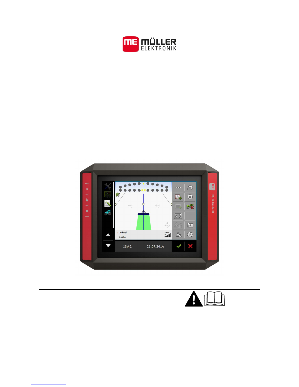
TRACK-Guide III
Version: V3.20140812
31302713-02-EN Read and follow these operating instructions.
Keep these operating instructions in a safe place for later
reference.

Company details
Installation and Operating Instructions
Product: TRACK-Guide III
Document number: 31302713-02-EN
From software version: 02.03.09
Original language: German
Müller-Elektronik GmbH & Co.KG
Franz-Kleine-Straße 18
33154 Salzkotten
Germany
Phone: ++49 (0) 5258 / 9834 - 0
Fax: ++49 (0) 5258 / 9834 - 90
Email: info@mueller-elektronik.de
Homepage: http://www.mueller-elektronik.de
Document
Copyright ©

Table of content s
31302713-02-EN V3.20140812 3
Table of contents
1
For your safety
6
1.1
Basic safety instructions
6
1.2
Intended use
6
1.3
Layout and meaning of warnings
6
1.4
Disposal
7
1.5
Instructions on retrofitting
7
2
About these Operating Instructions
9
2.1
Target group of these Operating Instructio ns
9
2.2
Layout of operating instructions
9
2.3
Layout of references
9
2.4
Directional information in these instructions
9
2.5
Current version
9
3
Product description
10
3.1
Scope of delivery
10
3.2
Terminal buttons
10
3.3
Terminal ports
10
3.4
Applications on the terminal
11
3.5
Information on the nameplate
12
4
Mounting and installation
14
4.1
Mounting the terminal in the vehicle cab
14
4.1.1 Mounting the standard bracket 14
4.1.2
Mounting the optional bracket
15
4.1.3
Mounting the optional adaptor
15
4.2
Connecting the terminal to the ISOBUS
16
4.3
Connecting the GPS receiver to the terminal
17
4.4
Connecting the camera to the terminal
18
4.4.1 Connecting the camera HQ 18
4.4.2
Connecting the camera NQ
19
4.5
Connecting the ISO printer to the terminal
20
4.6
Connecting the ME LightBar to the terminal
20
4.7
Connecting the on-board computer to the terminal
20
4.8
Connecting sensors to the terminal
21
5
Basic control principles
23
5.1
Initial start-up
23
5.2
Switching off the terminal
23
5.3
Terminal screen layout
24
5.4
Opening applications
25

Table of content s
4 31302713-02-EN V3.20140812
5.5
Moving an application
25
5.6
Saving and loading window arrangements
26
5.7
Hiding an application
27
5.8
Using the keyboard
27
5.9
Using a memory device
28
5.9.1
Using a SD card
28
5.9.2 Directories on the USB memory device 28
5.9.3
Displaying the content of the memory device on the terminal
29
5.10
Using two terminals
30
6
Configuring the terminal in the Service application
31
6.1
Changing the language
31
6.2
Basic settings
31
6.3
Enabling and disabling applications
33
6.4
Unlocking licenses for full versions
34
6.5
GPS receiver
35
6.5.1
Activating the GPS receiver
35
6.5.2 Configuring the GPS receiver 36
Parameters for the GPS receiver
36
RTK license for SMART-6L
38
GSM modem for SMART-6L 38
Configuring AG-STAR and SMART-6L GPS receivers for automatic steering
39
6.5.3
Recording GPS positions
40
6.6
Configuring the "GPS TILT-Mod ule" terrain comp ensa tion
41
6.7
Creating screenshots
41
6.8
Deleting pools
42
6.9
Configuring the joystick button allocations
42
6.10
Camera
43
6.10.1
Activating a camera
43
6.10.2 Operating the camera 43
6.11
Activating the ISO printer
44
6.12
Activating an external LightBar
44
7
Tractor-ECU application
45
7.1
Configuring the Tractor ECU
45
7.1.1
Calibrating the speed sensor
47
7.1.2
Entering the position of the GPS receiver
47
7.1.3 Calibrating an analog working position sensor 49
7.2
Results
49
7.2.1
Trip counter
49
7.2.2
Task-related counter
50
8
ISOBUS-TC task processing
51
8.1
Using ISOBUS-TC
51
8.2
Adjusting how you use ISOBUS-TC
51

Table of content s
31302713-02-EN V3.20140812 5
8.3
Configuring the list of connections
52
9
Serial Interface application
54
9.1
Transfer target rates via LH5000
54
9.2
Switching sections and transferring target rates via ASD
55
10
File Server application
58
11
Technical specifications
59
11.1
Technical specifications of the terminal
59
11.2
Assignment plans
59
11.2.1
Port A (CAN bus)
59
11.2.2 Port B 60
11.2.3
Port C (RS232)
61
11.2.4
CAM port
62
11.2.5 ETH (Ethernet) port 62
12
Notes
63
1
For your safety
Basic safety instructions
6 31302713-02-EN V3.20140812
For your safety
Basic safety instructions
Please read the following safety instructions carefully before using the product for the first time.
▪ Do not operate the terminal while driving in road traffic. Come to a standstill in order to use the
unit.
▪ Before maintaining or repairing the tractor, always disconnect the connection between the tractor
and the terminal.
▪ Before charging the tractor battery, always disconnect the connection between the tractor and
the terminal.
▪ Before welding on the tractor or implement, always disconnect the power supply to the terminal.
▪ Do not make any unauthorized modifications to the product. Unauthorized modifications or use
may impair safety and reduce the service life or operability of the unit. Modifications are
considered unauthorized if they are not described in the product documentation.
▪ Follow all recognized safety, industrial and medical rules as well as all road traffic laws.
▪ The product does not include any user serviceable parts. Do not open the casing.
▪ Read the operating instructions to the agricultural device which you want to control by using the
product.
Intended use
The terminal is used to operate agricultural machinery equipped with ISOBUS job computers.
Intended use also includes compliance with the conditions for operation and repairs prescribed by the
manufacturer.
The manufacturer cannot be held liable for any personal injury or property damage resulting from
such non-compliance. All risk arising from improper use lies with the user.
All applicable accident prevention regulations and all other generally recognized safety, industrial,
and medical standards as well as all road traffic laws must be observed. Any unauthorized
modifications made to the equipment will void the manufacturer's warranty.
Layout and meaning of warnings
All safety instructions found in these Operating Instructions are composed in accordance with the
following pattern:
WARNING
This signal word identifies medium-risk hazards, which could potentially cause death or serious
physical injury, if not avoided.
CAUTION
This signal word identifies low-risk hazards, which could potentially cause minor or moderate
physical injury or damage to property, if not avoided.
1
1.1
1.2
1.3
For your safety
Disposal
1
31302713-02-EN V3.20140812 7
NOTICE
This signal word identifies actions which could lead to operational malfunctions if performed
incorrectly.
These actions require that you operate in a precise and cautious manner in order to produce
optimum work results.
There are some actions that need to be performed in several steps. If there is a risk involved in
carrying out any of these steps, a safety warning will appear in the instructions themselves.
Safety instructions always directly precede the step involving risk and can be identified by their bold
font type and a signal word.
1. NOTICE! This is a notice. It warns that there is a risk involved in the next step.
2. Step involving risk.
Disposal
When it has reached the end of its service life, please dispose of this product as
electronic scrap in accordance with all applicable waste management laws.
Instructions on retrofitting
Instructions on how to retrofit electrical and electronic farm equipment and/or
components
Agricultural equipment used today features electronic components and parts whose function can be
affected by other farm equipment which emits electromagnetic waves. Such effects could lead to
personnel being put in danger, if the following safety instructions are not adhered to.
When selecting components, make sure first of all that the retrofitted electrical and electronic
components comply with the current version of the EMC Directive 2004/108/EC and carry the CE
marking.
When retrofitting a machine with electrical and electronic farm equipment and/or components
connected to the vehicle's electrical system, it is your own responsibility to check whether the
installation causes interference with the vehicle's electronic system or other components. This
applies, in particular, to the electronic control of:
▪ electronic hitch control (EHR),
▪ front linkage,
▪ power take off (PTO),
▪ engine,
▪ gear.
The following requirements must be met in order to retrofit mobile communication systems (e.g. radio,
phone):
▪ All farm equipment must be approved and installed in accordance with the regulations applicable
in the respective country.
▪ The equipment must be installed as a fixed installation.
▪ The operation of portable or mobile farm equipment in the interior of the vehicle is only permitted
via a connection to a permanently installed exterior antenna.
Example
1.4
1.5
Selecting components
User responsibility
Additional requirements

1
For your safety
Instructions on retrofitting
8 31302713-02-EN V3.20140812
▪ The transmitting part must be spatially separated from the vehicle's electronic system.
▪ When attaching the antenna, pay attention to proper installation, including a sound ground
connection between the antenna and the vehicle's ground wire.
For information on wiring and installation as well as the maximum allowable current consumption,
please also refer to the installation guide provided by the machine manufacturer.

About these Operating Instructions
Target group of these Operating Instructions
2
31302713-02-EN V3.20140812 9
About these Operating Instructions
Target group of thes e Ope r a ting Instructions
These Operating Instructions are intended for personnel entrusted with installing and operating the
terminal.
Layout of operating instructions
The operating instructions explain step by step how you can perform certain operations with the
product.
We use the following symbols throughout these Operating Instructions to identify different operating
instructions:
Type of depiction
Meaning
1.
2.
Actions that must be performed in succession.
⇨
Result of the action.
This will happen when you perform an action.
⇨
Result of an operating instruction.
This will happen when you have completed all
steps.
Requirements.
In the event that any requirements have been
specified, these must be met before an action
can be performed.
Layout of references
If any references are given in these Operating Instructions, they will appear as:
Example of a reference: [➙ 9]
References can be identified by their square brackets and an arrow. The number following the arrow
shows you on what page the chapter starts where you can find further information.
Directional information in these instructions
All directional information in these instructions, such as "left", "right", "forward", "back", is relative to
the movement direction of the vehicle.
Current version
The current version of these instructions can be found on our website: www.mueller-elektronik.de.
2
2.1
2.2
2.3
2.4
2.5
3
Product description
Scope of delivery
10 31302713-02-EN V3.20140812
Product description
Scope of delivery
The following items are included in delivery:
▪ TRACK-Guide III terminal
▪ VESA holder and screws
▪ Bracket for mounting the terminal
▪ USB memory device
▪ Installation and Operating Instructions
▪ Operating instructions for the TRACK-Leader application - as a separate document.
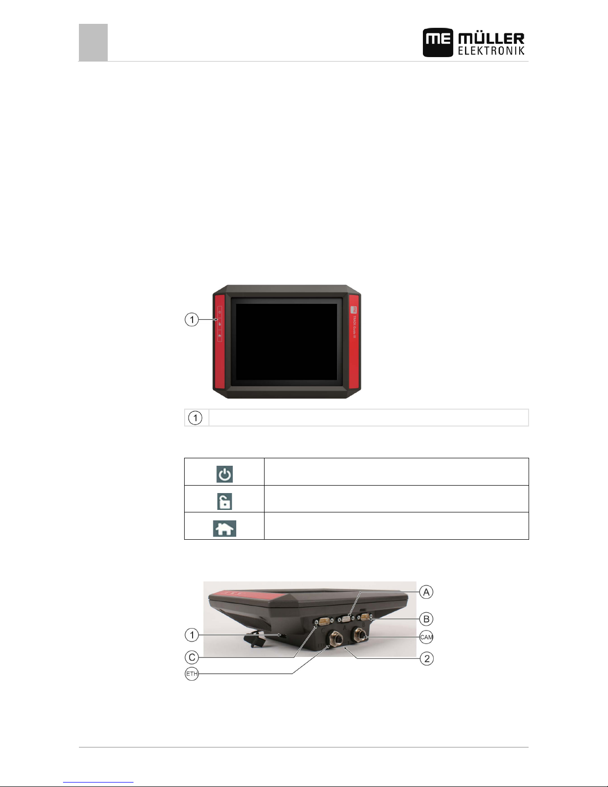
Terminal buttons
You will find a number of buttons on the housing of the terminal that are used to operate the terminal.
Terminal buttons
Function of the buttons
Switches the terminal on and off.
Creates screenshots.
Saves the window layout.
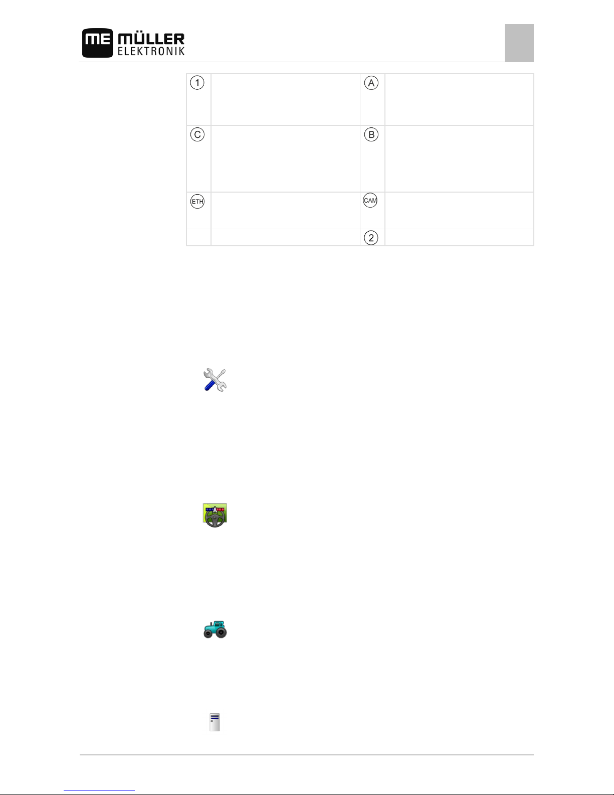
Terminal ports
Terminal ports
3
3.1
3.2
3.3
Product description
Applications on the terminal
3
31302713-02-EN V3.20140812 11
USB port for:
- USB memory device [➙ 28]
Port A
CAN bus port for:
- ISOBUS basic equipment [➙ 16]
- Connection to the tractor CAN bus
Port C
RS232 serial port for:
- GPS receiver [➙ 17]
- "GPS TILT-Module" terrain compensation
- ME-LightBar [➙ 20]
Port B
See section: Pin assignment Port B [➙ 60]
ETH port
M12 port for:
- Ethernet
CAM port
Port for an analog camera [➙ 43]
Slot with the SD card
Applications on the terminal
The terminal is delivered with a range of installed application (apps). Most of these can be used
immediately. Some applications you can only test for a limited period of time. If you like some specific
application, you can order a license from Müller-Elektronik and unlock the full version of the
application.
The full versions of the following applications are installed on the terminal:
▪
- Service application.
The Service application allows you to:
– Configure the terminal.
– Enable and disable other applications.
– Enter license activation codes.
– Enable drivers for connected devices.
– Configure the GPS settings.
▪
- TRACK-Leader application with SECTION-Control and further modules.
The TRACK-Leader application enables you to process exact parallel swaths in the field.
Additional modules in the application handle the following tasks:
– Automatic section control in order to minimize overlaps.
– Automatic vehicle steering in the field.
– Transfer target rates from a prescription map to the ISOBUS job computer.
▪
- Tractor-ECU application.
The Tractor-ECU application is used to record all settings around the tractor.
This allows you to:
– Input the position of the GPS receiver.
– Set the GPS receiver as the speed signal source.
▪
- File Server application
3.4
Full versions
3
Product description
Information on the nameplate
12 31302713-02-EN V3.20140812
This application is used to define a save location on the terminal. This save location can be used
by all ISOBUS implements which do not have their own USB interface.
▪
- Serial Interface application
This application enables a data exchange between the terminal and an on-board computer via
the serial interface. In this way, you can also use the GPS signal for machines which are not
ISOBUS-compatible. You can transfer target rates to the on-board computer or switch sections.
The data is sent using the LH5000 or ASD protocols.
If you want to use the ASD protocol, you must activate the "ASD-Protocol" license.
▪
- Camera.
The Camera application displays on the screen the image from the camera which is connected
to the terminal.
Optionally you can activate the following software:
▪ ISOBUS interface (ISOBUS-UT)
The terminal enables you to operate ISOBUS job computers which are ISO 11783 compliant.
The user interfaces for operating a job computer are shown on the terminal screen if this is
connected to the ISOBUS connector of the vehicle.
The ISOBUS interface has no icon of its own. The icon for the connected job computer will
always be displayed in the selection menu.
▪
- ISOBUS-TC application.
The ISOBUS-TC application (task controller) provides an interface between a Farm Management
Information System (FMIS), the terminal and the ISOBUS job computer. ISOBUS-TC allows you
to use the terminal to process ISO-XML files with planned task data from your PC based FMIS. If
you do not have an FMIS, you can setup and process tasks on the terminal.
The ISOBUS-TC application complies with Part 10 of Standard ISO11783.
▪
- FIELD-Nav application.
FIELD-Nav is a navigation system for agricultural applications. This enables you to find your way
to any field.
You will find the operating instructions on the Müller-Elektronik website.
Information on the nameplate
You will find a nameplate sticker on the back of the terminal. On this sticker, you can find all the
information you need to definitively identify the product.
Have these details ready when you contact Customer Services.
Abbreviations on the rating plate
Abbreviation
Meaning
Software version
You can see the installed software version on the Start Screen of the
Service application:
Hardware version
Optional software
3.5
Product description
Information on the nameplate
3
31302713-02-EN V3.20140812 13
Abbreviation
Meaning
Operating voltage
The terminal may only be connected to voltages within this range.
Customer number
If the terminal was manufactured for an agricultural machinery
manufacturer, the agricultural machinery manufacturer's item number
will be shown here.
Serial number
4
Mounting and inst allation
Mounting the terminal in the vehicle cab
14 31302713-02-EN V3.20140812
Mounting and installation
Mounting the terminal in the vehicle cab
You need a bracket to mount the terminal in the vehicle cab. The following brackets are available.
Item number Type Scope of
delivery?
Properties
31322506
Standard bracket
Yes
31322507 Optional bracket No
▪ For a more sturdy attachment of the
terminal.
31322508 Optional adaptor No
▪ Is mounted on bracket 31322507.
▪ Suitable for vehicles without a B
column.
▪ Is mounted around a pipe.
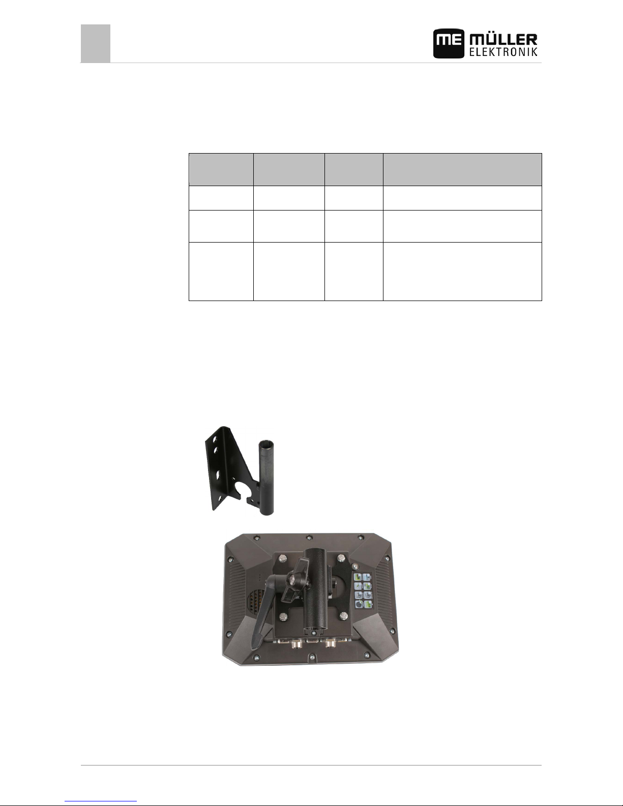
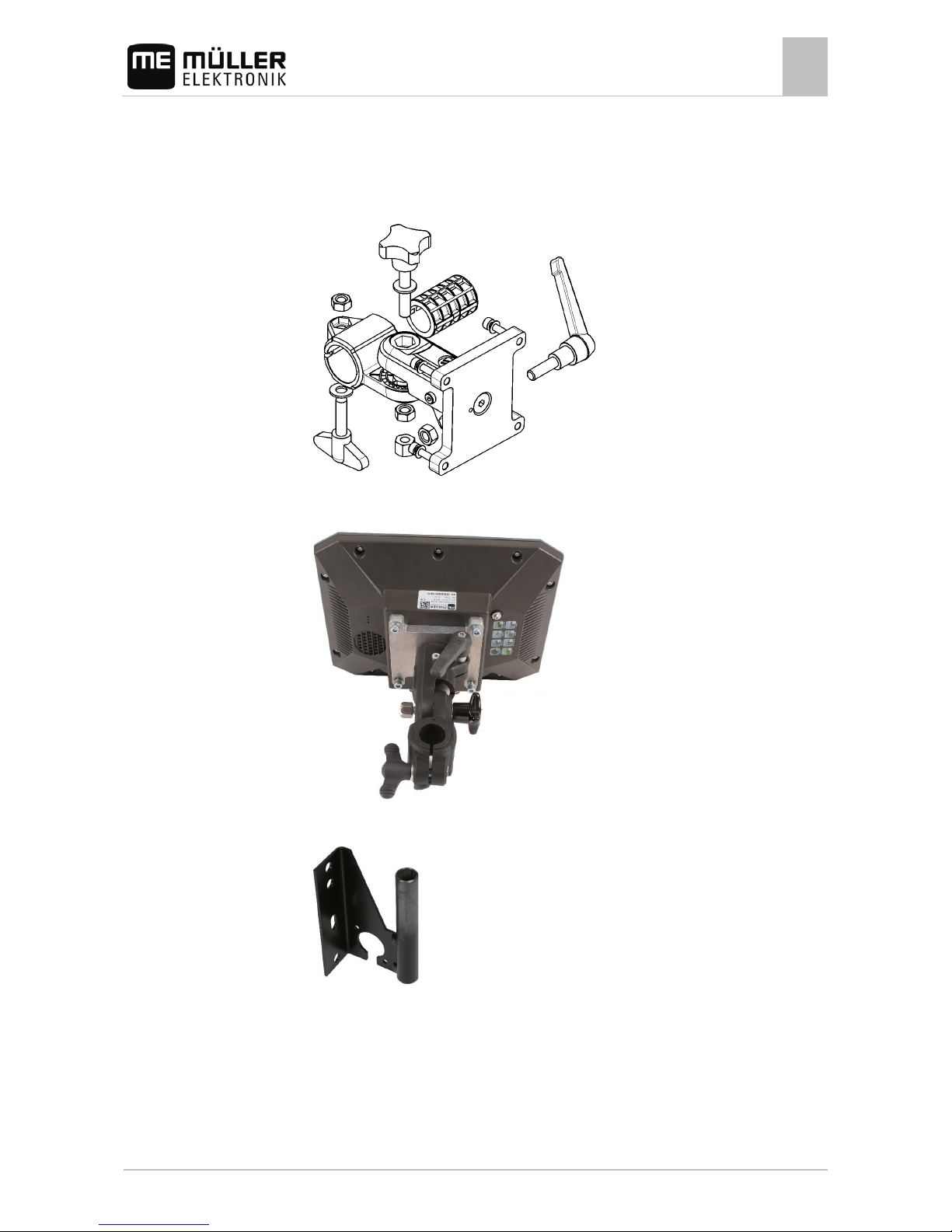
Mounting the standard bracket
You have the VESA bracket assembly kit within reach.
1. Assemble the bracket together.
2. Secure the bracket with the four screws on the back side of the terminal.
3. Secure the terminal in the vehicle cab. You can, for example, use the ME mounting bracket for
this purpose. It is included in the scope of delivery of the ISOBUS basic equipment.
⇨ Your terminal should be mounted as follows:
4. Check that your terminal is firmly mounted.
⇨ You can now connect cables to the terminal. [➙ 10]
4
4.1
4.1.1
Procedure
Mounting and inst allation
Mounting the terminal in the vehicle cab
4
31302713-02-EN V3.20140812 15
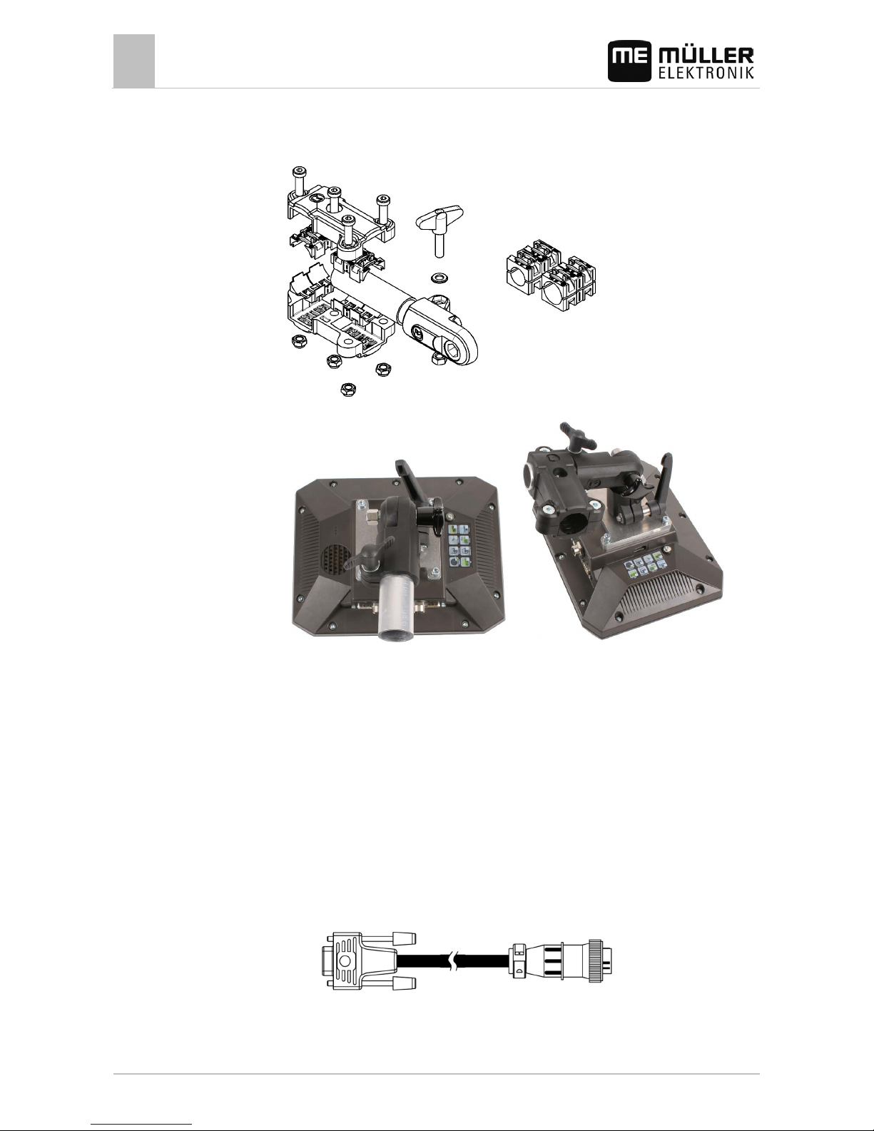
Mounting the optional bracket
You have the bracket assembly kit within reach.
1. Assemble the bracket together.
2. Secure the bracket with the four screws on the back side of the terminal.
3. Put the bracket into the desired position. See below:
4. Secure the terminal in the vehicle cab. You can, for example, use the ME mounting bracket for
this purpose. It is included in the scope of delivery of the ISOBUS basic equipment.
5. Check that your terminal is firmly mounted.
Mounting the optional adaptor
If you want to mount your terminal in a vehicle that does not have a B column, you can install an
adaptor onto bracket 31322507. This adaptor can be mounted around a pipe.
4.1.2
Procedure
4.1.3
4
Mounting and inst allation
Connecting the terminal to the ISOBUS
16 31302713-02-EN V3.20140812
▪ Adaptor for round pipe systems, for pipes with a diameter of 20, 25 or 30 mm, item number:
31322508
1. Assemble the adaptor together.
2. Connect the adaptor with the bracket.
3. Put the bracket and the adaptor in the desired position.
4. Check that everything is firmly mounted.
Connecting the terminal to the ISOBUS
If you purchase the ISOBUS-UT app in order to be able to also operate ISOBUS job computers with a
terminal, you must connect this to the ISOBUS.
You will need a different connection cable for this, depending on the model of your tractor.
▪ In tractors which have been subsequently upgraded with an ISOBUS-basic vehicle harness from
Müller-Elektronik, use connector cable A from the ISOBUS-basic vehicle harness.
▪ In tractors which are equipped as standard with ISOBUS and which have an ISOBUS In Cab
Connector, you will need the following connector cable:
– D-Sub <-> CPC connector cable, item no. 30322541
▪ In tractors which are fitted with their own ISOBUS terminal, but in which there is however no
ISOBUS In Cab Connector, you can ask for the ISOBUS In Cab Connector to be retrofitted.
Procedure
4.2
Mounting and inst allation
Connecting the GPS receiver to the terminal
4
31302713-02-EN V3.20140812 17
– You can order the appropriate cable from Müller-Elektronik. Our sales team will be glad to
advise you.
– For certain tractors, you can retrofit the connector cable without the ISOBUS In Cab
Connector.
– In certain versions, you will also require the D-Sub <-> CPC connector cable, item no.
30322541
When there is more than one terminal in the tractor cab, you may need to change certain settings in
order to enable two-way communication. Find out more: Using two terminals [➙ 30]
1. Connect the 9-pin plug A of the basic vehicle harness to the CAN port of the terminal.
2. Tighten the safety screws on the connector.
Connecting the GPS receiver to the terminal
Find out how to connect Müller-Elektronik GPS receiver to the terminal via the GPS receiver's
Operating Instructions.
When mounting the terminal in a vehicle which is already fitted with a GPS receiver and another
ISOBUS terminal, you must:
▪ connect the GPS signal to the terminal from Müller-Elektronik;
▪ configure the GPS receiver.
To connect the terminal to a GPS receiver which is already installed on the vehicle:
1. Find out how you can direct the signal from the GPS receiver to the terminal. This can differ for
every vehicle or GPS receiver: Vehicles can be fitted with a GPS socket in the cab, a GPS
receiver with a serial output or serial outputs to the ISOBUS terminal.
2. Check what cable you will use to connect GPS signal to the serial socket on the terminal from
Müller-Elektronik.
3. Connect the GPS signal to the serial socket of the terminal from Müller-Elektronik.
4. Configure the GPS receiver so that it can communicate with the terminal from Müller-Elektronik.
You can find the necessary specifications for this in the table below.
5. Activate the "Standard" GPS driver on the terminal.
Configuration
Frequencies
5 Hz (GPGGA, GPVTG)
1 Hz (GPGSA, GPZDA)
Transmission rate
19200 baud
Data bits
8
Parity no
Stop bits
1
Flow control
None
Procedure
4.3
Procedure

4
Mounting and inst allation
Connecting the camera to the terminal
18 31302713-02-EN V3.20140812
Connecting the camera to the terminal
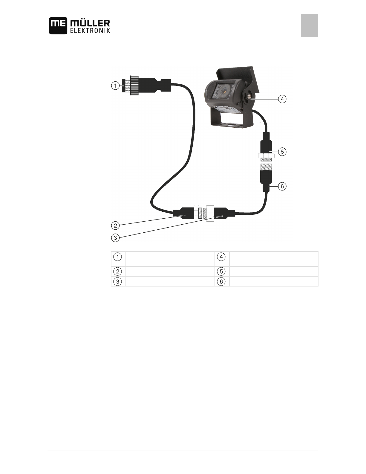
Connecting the camera HQ
Camera HQ - Connection to the Touch Terminal
Plug for connection to the terminal.
CAM port
Camera HQ
Extension cable
Camera plug
Connector for the camera plug
1. Assemble the camera together with its bracket, as described in the assembly instructions of the
camera manufacturer.
2. Connect the camera to the extension cable.
3. CAUTION! When laying out the extension cable, ensure that there are no kinks and that
no one can stumble over the laid-out cable.
4. Connect the extension cable to the CAM port of the terminal.
5. Secure the camera.
6. Activate the camera. [➙ 43]
4.4
4.4.1
Procedure
Mounting and inst allation
Connecting the camera to the terminal
4
31302713-02-EN V3.20140812 19
Connecting the camera NQ
Camera with adapter cable
Plug for connection to the terminal.
CAM port
Camera
Connector for the adapter cable
Camera plug
Connector for the extension cable
Connector for the camera plug
1. Connect the cables to each other as shown in the figure. Pay attention to cable lengths when
doing so.
2. CAUTION! When laying out the cable, ensure that there are no kinks in the cable and that
no one can stumble over the laid-out cable.
3. Lay out the cable. Ensure that the cable reaches the terminal and is not pulled out during
operation.
4. Attach the cable with the provided cable ties.
5. Secure the camera. Use the white cardboard drilling template from the quick start guide for this
purpose.
6. Connect the camera to the terminal. Use the CAM port to do this.
7. Activate the camera. [➙ 43]
8. When disconnecting the cable from the terminal, use the enclosed rubber gasket to seal the
exposed connector.
4.4.2
Procedure

4
Mounting and inst allation
Connecting the ISO printer to the terminal
20 31302713-02-EN V3.20140812
Connecting the ISO printer to the terminal
The ISO printer is used to print out information from an ISO-XML task.
9-pin Sub-D plug for connection to ISOBUS
Plug for connection to ISO printer socket
ISO printer
Connector for connection to the terminal
ISO printer socket
CAN-Bus connection
When you connect a GPS receiver to the terminal, you must activate [➙ 44] and configure it.
Connecting the ME LightBar to the terminal
The ME LightBar is a parallel guidance display made by Müller-Elektronik, which can be mounted
near the windshield.
The ME LightBar works with position data and guidance lines that are provided by the TRACK-Leader
app. This is why you need the TRACK Leader App to be able to use the ME LightBar.
External LightBar
Connector for connection to the terminal
Plug for connecting a GPS receiver
Serial port RS232
After connecting an external LightBar to the terminal, you must activate [➙ 44] it.
Connecting the on-board computer to the terminal
You can connect a range of on-board computers (non-ISO computers), which communicate using the
LH5000 protocol or the ASD interface, to the terminal.
4.5
4.6
4.7

Mounting and inst allation
Connecting sensors to the terminal
4
31302713-02-EN V3.20140812 21
An appropriate connector cable for each on-board computer which can be connected is available
from Müller-Elektronik. Our sales team will be glad to advise you.
You can find a list of on-board integrated display/controllers that we have tested here:
▪ Transfer target rates via LH5000 [➙ 54]
▪ Switching sections and transferring target rates via ASD [➙ 55]
For other on-board integrated display/controllers and for on-board integrated display/controllers with
other software versions, this function may not work at all or different from how it is described in these
instructions. Because the operating mode and configuration depends on the on-board integrated
display/controller. You must contact the on-board integrated display/controller manufacturer for this.
On-board computer
Null modem cable
Adapter cable*
Available as a set with Cable 3, item number:
3032254800
Port B on the terminal
*When using an Amatron3 or Amatron+ as on-board integrated display/controller, you will only need a
traditional null modem cable. (Amatron3 and Amatron+ are on-board integrated display/controller
from Amazone)
Connecting sensors to the terminal
The terminal provides you with the possibility of connecting a sensor or the tractor's 7-pole signal
socket to port B. This allows you for example to use the working position signal in the TRACK-Leader
parallel guide.
The working position sensor that can be purchased from Müller Elektronik is fitted with a round 3-pin
plug. In order to connect this to the terminal, you will need an adapter cable.
Adaptor cable for the ME-sensor Y working position sensor
Adapter cable
Item number
3-pin to 9-pin 31302499
You can also connect the terminal to the signal socket.
4.8

4
Mounting and inst allation
Connecting sensors to the terminal
22 31302713-02-EN V3.20140812
Cable to the signal socket
Ports Connection Item number
7-pin to 9-pin socket Cable direct to the signal socket
Transmits the speed and working
position.
30322548

Basic control principles
Initial start-up
5
31302713-02-EN V3.20140812 23
Basic control principles
Initial start-up
You must at least perform the following settings during initial startup:
▪ Change the language [➙ 31].
▪ Configure the "Work with ISO-XML?" parameter in the ISOBUS-TC application [➙ 51].
▪ Configure the GPS receiver. [➙ 36]
▪ Enter the position of the GPS receiver [➙ 47].
To switch on the terminal:
The terminal is installed and connected to the ISOBUS basic vehicle harness.
1. Press and hold the
button for approx. 3 seconds.
⇨ The terminal will beep briefly.
⇨ The terminal screen remains dark for approx. 10 seconds until the applications are loaded in
the background.
⇨ The Start screen of the terminal will appear:
⇨ You have now started the terminal.
Switching off the terminal
To switch off the terminal:
1. Press and hold the
button for approx. 3 seconds.
⇨ You have now switched off the terminal.
5
5.1
Procedure
5.2
Procedure

5
Basic control principles
Terminal screen layout
24 31302713-02-EN V3.20140812
Terminal screen layout
Terminal screen layout
Selection menu
You can open applications in the "Selection
menu" area.
Wide additional window
Main window
This area enables you to operate applications.
Touching the terminal screen in the "Main
window" area will actuate the function whose
icon you have touched.
The controls depend on the opened
applications.
System icons
System icons
Icon
Meaning
Has no function in this area.
When this icon appears in other areas, it is used for confirmation
purposes.
Has no function in this area.
When this icon appears in other areas, it is used for cancellation or
deletion purposes.
Has no function in the current software version.
Has no function in the current software version.
5.3

Basic control principles
Opening applications
5
31302713-02-EN V3.20140812 25
Opening applications
An application opens when it appears in the main window or in an additional window.
To open an application:
1. Find the function icon for the desired application in the Selection menu area. For example, the
icon:
2. Tap the function icon of the application:
⇨ The application will appear in the main window:
⇨ The function icon of the application in the Selection menu now appears darker. This tells
you that this application is already open. You will no longer be able to open it from the
Selection menu.
⇨ If the main window is occupied, the application that is already opened will be moved to a
free additional window. If this is occupied, the application that is already opened will be
moved back to the Selection menu. Their icon becomes bright again. However, it can
continue to work in the background.
Moving an application
You can move any application from the main window to one of the additional windows or to the MEHeader.
To move an application from the main window to an additional window:
5.4
Procedure
5.5
Procedure

5
Basic control principles
Saving and loading window arrangements
26 31302713-02-EN V3.20140812
You have opened an application in the main window. For example, the Service application:
1. Tap the additional window:
⇨ The application will now appear in the additional window:
2. Tap the additional window with the application.
⇨ The application will once again appear in the main window.
Saving and loading window arrangements
You can save and load the arrangement of the applications in the windows.
To save the arrangement:
1. Hold the button
pressed down until the terminal beeps twice.
⇨ The arrangement will be saved.
To load a saved arrangement:
1. Briefly press the button:
⇨ The arrangement will be loaded.
5.6
Procedure
Procedure

Basic control principles
Hiding an application
5
31302713-02-EN V3.20140812 27
Hiding an application
If you do not have enough space on the terminal screen to open new applications, you can hide an
application. The application will not be shut down, but will instead continue to run in the background.
To hide an application:
1. Open the application in the additional window.
2. Move the application to the selection menu.
Using the keyboard
In order to enable you to also write numbers or text on the terminal, a keyboard will appear on the
terminal screen whenever this is necessary.
Major icons
Icon
Meaning
12#
Abc
Changes the buttons on the keyboard.
Deletes a character.
Moves the cursor.
Saves the input.
Cancels the input.
Switches between upper and lower case letters.
Keyboard for inputting text and numbers.
5.7
Procedure
5.8

5
Basic control principles
Using a memory device
28 31302713-02-EN V3.20140812
Keyboard for inputting text.
Using a memory device
The terminal can work with two kinds of memory devices:
1. With a built-in Micro-SD card. This will be used as storage for most applications.
2. Using a USB memory device.
It is used only for the following purposes:
▪ For data transmission [➙ 28]
▪ For saving screen shots
▪ For working with shp files in the TRACK-Leader application.
farmpilot
If you use the farmpilot portal, do not use a USB memory device, but only the SD card.
Using a SD card
The terminals applications save most data [➙ 28] directly onto the SD card.
In order to exchange data between the terminal and a PC, you will need to proceed differently for
each application. You can find out more about this in the instructions for each application.
Here is an overview of the directories on the USB memory device: Directories on the USB memory
device [➙ 28]
Directories on the USB memory device
As soon as you insert the USB memory device into the terminal, various directories will be created on
the terminal. You will need to set up other directories by yourself.
Each directory may only contain certain data, so that the applications on the terminal can use this
data.
▪ "ApplicationMaps"
– Files: Prescription maps in .shp format.
– Purpose: TRACK-Leader. For use with "VARIABLE RATE-Control".
▪ "FIELDNav"
– Files: .iio, .data
– Purpose: Map material will be saved in this directory.
– The directory will be created when the FIELD-Nav license is activated.
5.9
5.9.1
5.9.2

Basic control principles
Using a memory device
5
31302713-02-EN V3.20140812 29
▪ "GIS"
– Files: Field data, such as field boundaries, in the following formats: .shp, .dbf, .shx.
– Purpose: TRACK-Leader. Export and import for GIS.
▪ "NgStore"
– Files: .iio, .data
– Purpose: TRACK-Leader. Standard directory for saved routes and fields.
▪ "Screencopy"
– Files: .bmp
– Purpose: Screenshots are saved here.
– The terminal will create this directory automatically when the "Screenshot" parameter is
activated in the "Terminal" menu and you create a screenshot.
▪ "Taskdata"
– Files: .xml
– Purpose: The directory may only contain XML files which originate from an ISO-XML
compatible FMIS. The ISOBUS-TC application accesses this data.
– You must create this directory yourself.
▪ "GPS"
– Files: .txt
– Purpose: GPS positions are saved in a file in the directory. This will enable Customer
Service to reconstruct the traveled distance.
– The directory will be created if you activate the "Record and save data" parameter.
▪ "fileserver"
– Files: All file formats are acceptable.
– Purpose: Files which are to be imported or exported in the File Server application are saved
in this directory.
▪ "documents"
– Files: .txt
– Purpose: Records for all completed tasks are saved in this folder.
Displaying the content of the memory device on the terminal
You can view the content of the memory device directly on the terminal.
1. Insert the memory device (USB memory device or SD card) into the terminal.
2. Open the "Service" application.
3. Tap on "USB 1" or on "SDCard".
⇨ The content of the USB memory device will be displayed.
⇨ The content of the SD card can be found in the "ME-TERMINAL " folder.
5.9.3
Procedure

5
Basic control principles
Using two terminals
30 31302713-02-EN V3.20140812
Using two terminals
When installing the terminal in a tractor in which there is already another terminal, you must configure
both terminals so that communication works between both units.
The following table will tell you which settings you need to configure, and the chapters in which these
are described.
Parameter Chapter
ISOBUS-UT: Function instance
Basic settings [➙ 31]
Login as ISOBUS-UT
Basic settings [➙ 31]
Communication with ISOBUS-TC
Configuring the Tractor ECU [➙ 45]
Configuring the list of connections
Configuring [➙ 52] the list of connections
5.10

Configuring the terminal in the Service applicati on
Changing the language
6
31302713-02-EN V3.20140812 31
Configuring the terminal i n the Service application
Changing the langua ge
When you switch on the terminal for the first time, the text may appear in a foreign language (in
German).
If you change the language in the Service application, you also change the language for all
applications and the ISOBUS job computer.
If a connected ISOBUS job computer cannot activate the selected language, a standard language will
be activated.
1. - Open the Service application.
⇨ The application start screen will appear:
2. Tap "Terminal".
⇨ A list of parameters will appear.
3. Slide your finger over the terminal screen from the bottom to the top.
⇨ New parameters appear.
4. Tap "Language" ("Sprache").
⇨ A list of abbreviations of available languages will appear.
5. Tap the abbreviation for your language.
⇨ The abbreviation is marked with a green dot.
6.
- Confirm.
⇨ The "Terminal" screen will appear.
7. Restart the terminal.
Basic settings
The basic settings include: Language, Time, Measurement units.
All settings which you make here will also apply to other applications and in connected ISOBUS job
computers.
1. - Open the Service application.
6
6.1
Procedure
6.2
Procedure

6
Configuring the terminal in the Service applicati on
Basic settings
32 31302713-02-EN V3.20140812
⇨ The application start screen will appear:
2. Tap "Terminal".
⇨ A list of parameters will appear. See the table below.
3. To change the value of any of the parameters, tap the desired parameter.
⇨ A window will appear, into which you can input the value of the parameter as a number, or
select from a list.
4.
- Confirm.
5. Restart the terminal.
Parameters in the "Terminal" menu
Parameter name
Function
Brightness Day Brightness of the terminal screen during the day.
Brightness Night
Brightness of the terminal screen at night.
Keyboard brightness
Lighting of the buttons.
Volume
Volume of the terminal.
Date
Current date.
Time Current time.
Time zone
Time difference in relation to GMT.
Language Language of the applications on the terminal screen.
Measurement units
Measurement system.
Screenshot When this parameter is activated, you can create screen shots
on the terminal.
ISOBUS-UT: Function instance Use this parameter if you want the ISOBUS interface to assign a
specific "Function instance". This will enable you to set the
terminal to which you want to connect an ISOBUS job computer.
Login as ISOBUS-UT Activate this parameter if you want the ISOBUS job computer to
be displayed on the terminal. This parameter must be activated in
most instances. On very few self-propelled agricultural machines,
the parameter must be deactivated.

Configuring the terminal in the Service applicati on
Enabling and disabling applications
6
31302713-02-EN V3.20140812 33
Parameter name
Function
Number of navigation buttons The terminal provides a maximum of 12 function icons in each
application.
When you connect an ISOBUS job computer that has more
functions in a single screen to the terminal, their function icons
are spread over multiple pages. Furthermore, navigation buttons
appear that can be used to scroll to the next page.
The number indicates how many buttons should be used to scroll
between multiple pages with function icons.
Enabling and disabling applications
In the "Service" application you can activate and deactivate other applications that are installed on
the terminal.
The applications are installed in packages, in so-called plug ins. A plug-in can contain several
applications.
You can for example deactivate a plugin if you do not want to use it. The plug-in will then not be
displayed in the selection menu.
Name of the plug-in Includes the following applications
TRACK-Leader TRACK-Leader
SECTION-Control
TRACK-Leader TOP
VARIABLE RATE-Control
ISOBUS-TC
ISOBUS-TC
Tractor-ECU Tractor-ECU
Camera The terminal screen will show the image from the connected
camera.
FIELD-Nav FIELD-Nav
File Server
File Server
Serial Interface
Serial interface for the transfer of data to the on-board computer.
To activate and deactivate plug-ins:
1.
- Open the Service application.
2. Tap "Plug-ins".
⇨ The "Plug-ins" screen will appear.
3. To activate or disable a plug-in, tap it.
⇨ A plug-in is activated when a checkmarker appears in front of its name.
6.3
Procedure

6
Configuring the terminal in the Service applicati on
Unlocking licenses for full versions
34 31302713-02-EN V3.20140812
4. Restart the terminal.
Unlocking licenses for full version s
Several applications are pre-installed on the terminal, which you can use for trial purposes for up to
50 hours. After this time has elapsed, they will be automatically deactivated.
"Licenses" screen
Screen name
Name of the application
Unlocked applications are marked with check
marks.
You can see how long you can still use a test
version in the brackets: in hours and minutes.
Un-checked applications are locked.
18-digit alphabetical code of the application
You will need an activation key to unlock a license. To receive this, you will need to purchase a
license from Müller-Elektronik.
If you request the activation key by phone or by email, you will be required to give our staff the
following information:
▪ The name of the application for which you require a license.
▪ The 18-digit alphabetical code of the application. You will find this on the "Licenses" screen.
▪ Serial number of the terminal – Found on the nameplate on the reverse of the terminal.
▪ Item number of the terminal – Found on the nameplate on the back of the terminal.
To unlock a license:
1.
- Open the Service application.
2. Tap "Licenses".
3. Order an activation key from Müller-Elektronik using the 18-digit alphabetical code.
4. Tap the name of the license that you want to unlock.
⇨ The keyboard will appear.
5. Enter the activation key.
6.
- Confirm.
⇨ The "Licenses" screen will appear.
7. Restart the terminal.
⇨ The full version of the application is now unlocked.
6.4
Procedure

Configuring the terminal in the Service applicati on
GPS receiver
6
31302713-02-EN V3.20140812 35
GPS receiver
When you connect a GPS receiver to the terminal, you must activate and configure it.
Activating the GPS receiver
In order to enable the GPS receiver, you must first select the driver for the connected receiver.
A driver is a small program that controls connected device. The drivers for the devices supplied by
Müller-Elektronik are pre-installed on the terminal.
Available drivers
Driver name GPS receiver
deactivated
No GPS receiver is connected.
A100, A101 Drivers for the A100 and A101 GPS receivers from Müller-
Elektronik, if they are connected to the serial interface.
AG-STAR, SMART-6L Drivers for the AG-STAR and SMART-6L GPS receivers from
Müller-Elektronik, if they are connected to the serial interface.
PSR CAN Select this driver if the GPS receiver is connected to the PSR
steering job computer. PSR is a steering computer by the
Reichhardt company. The signals are transmitted to the terminal
through the CAN cable. The receiver will be configured directly in
the PSR application.
Standard Drivers for unknown GPS receivers, if they are connected to the
serial interface.
This driver is activated by default. The connected GPS receiver
cannot thus be configured.
TRACK-Leader AUTO® Select this driver if a GPS receiver is connected to the TRACK-
Leader AUTO® steering job computer.
CAUTION
Incorrect driver
Damage to the GPS receiver.
◦ Before connecting a GPS receiver to the terminal, you must always activate the appropriate
driver.
To activate the driver:
1.
- Open the Service application.
2. Tap "Driver".
3. Tap "GPS".
⇨ The installed drivers will appear.
6.5
6.5.1
Procedure

6
Configuring the terminal in the Service applicati on
GPS receiver
36 31302713-02-EN V3.20140812
4. Tap the appropriate driver.
5.
- Confirm.
6. Restart the terminal.
Configuring the GPS receiver
The internal software for each GPS receiver must be configured. You can configure the following
GPS receivers offered by Müller-Elektronik via the terminal:
▪ A100, A101
▪ AG-STAR, SMART-6L
All other GPS receivers must be configured in accordance with their manufacturer's instructions.
Function icon
Meaning
Reads the configuration of the GPS receiver.
Restores the manufacturer's default settings.
Opens the license menu. [➙ 38]
Only appears for a SMART-6L DGPS/Glonass receiver for entering an
activation license.
The GPS receiver is connected to the terminal.
The GPS receiver is connected directly to the terminal. Additional devices such as ME LightBar
or tilt module may not be connected in between.
The correct GPS driver is activated.
1.
- Open the Service application.
2. Tap "GPS".
⇨ The "Settings" screen appears.
⇨ The following message will appear during initial configuration: "GPS receiver identified.
Read the configuration?"
3. To confirm, tap "Yes". To cancel, tap "No".
⇨ The terminal reads the current configuration of the GPS receiver.
⇨ You can now see all of the configurable parameters.
4. Reconnect all of the additional devices that you had disconnected for the configuration.
Parameters for the GPS receiver
Baud rate
Only appears when the "Standard" driver is selected.
Setting for the speed at which the GPS receiver sends data to the terminal. The parameter sets the
baud rate for the terminal.
Satellite 1 and Satellite 2
6.5.2
Procedure

Configuring the terminal in the Service applicati on
GPS receiver
6
31302713-02-EN V3.20140812 37
Satellite 1 – primary DGPS satellite. The DGPS receiver will connect to this satellite in the first
instance.
Satellite 2 – secondary DGPS satellite. The DGPS receiver will only connect to this satellite in the
event that the primary satellite fails.
Your satellite selection will depend on which satellite currently has the best availability in your region.
Potential values:
▪ "Auto"
The software automatically selects the current best satellite. This setting is not recommended, as
it slows down the start-up of the DGPS receiver.
▪ Name of the satellite. Which satellites are shown here is dependent on the driver and correction
signal that you have activated.
Steering
This parameter activates the "Automatic steering" assistance function in the GPS receiver.
If you want to connect your existing GPS receiver to a steering job computer, you have to configure
the "Steering" parameter.
Potential values:
▪ "Without automatic steering"
Deactivates automatic steering assistance.
▪ "TRACK-Leader TOP"
Activates automatic steering assistance with TRACK-Leader TOP.
▪ "TRACK-Leader AUTO"
Activates automatic steering assistance with TRACK-Leader AUTO.
Correction signal
Type of correction signal for the DGPS receiver.
The correction signals which are available is dependent on the activated driver.
Potential values:
▪ For the "A100, A101" driver:
– "WAAS/EGNOS"
Correction signal for Europe, North America, Russia and Japan.
– "E-DIF"
Internal calculation of correction data.
Only functions with a special version of the A100 DGPS receiver, item no. 30302464. This
receiver is no longer sold by Müller-Elektronik.
▪ For the "AG-STAR, SMART-6L" driver
When a AG-STAR DGPS/Glonass receiver is connected:
– "EGNOS-EU"
– "WAAS-US"
– "MSAS-JP"
– "EGNOS-EU + GL1DE"
– "WAAS-US + GL1DE"
– "MSAS-JP + GL1DE"

6
Configuring the terminal in the Service applicati on
GPS receiver
38 31302713-02-EN V3.20140812
– "GPS/Glonass GL1DE 1"
– "GPS/Glonass GL1DE 2"
When a SMART-6L DGPS/Glonass receiver is connected:
– EGNOS/WAAS
– EGNOS/WAAS + GL1DE
– GL1DE
– RTK radio (RTK license required [➙ 38])
– RTK GSM (RTK license required [➙ 38])
Terrain compensation
The GPS TILT-Module terrain compensation is configured using this parameter.
You can order the terrain compensation from Müller-Elektronik with the following item number:
30302495.
RTK license for SMART-6L
You will need a SMART-6L DGPS/Glonass receiver and RTK license in order to work with RTK
correction signals.
When purchasing a GPS receiver with an RTK license, the licence from Müller-Elektronik will be
entered. You only have to enter the licence yourself when it is purchased at a later date.
1. - Open the Service application.
2. Tap "GPS".
⇨ The "Settings" screen will appear.
3.
- Open the license menu.
4. Tap "License code".
⇨ The "License menu" screen will appear.
⇨ You can see the serial number and firmware version on the screen. You will need these
when ordering the license code.
5. Enter the license code.
6.
- Confirm.
GSM modem for SMART-6L
If you are using the DGPS/Glonass SMART-6L receiver with a GSM modem, you can adjust the
existing configuration.
1. - Open the Service application.
2. Tap "GPS".
3. The "Settings" screen appears.
4.
- Open the configuration menu.
Procedure
Procedure

Configuring the terminal in the Service applicati on
GPS receiver
6
31302713-02-EN V3.20140812 39
5. Configure the parameters. The explanations for the individual parameters can be found in the
table at the end of this section.
6.
- Save the changes.
⇨ The following message appears: "Should the data be transmitted to the modem?"
7. "Yes" - to confirm.
⇨ The data is being transmitted to the modem. This will take approx. 30 seconds.
⇨ After a restart, the new data will be displayed on the "NTRIP configuration" screen.
Parameter
Meaning
Possible entries
APN Connection to the provider. Provider URL or IP address.
User Name for the Internet access. The name is the
same for all users of a provider.
Name that was given by the provider. Some
providers do not require entering a name.
Password Password for the Internet access. The password is
the same for all users of a provider.
Password that was given by the provider.
Some providers do not require entering a
password.
URL/IP Connection to the correction data server. Correction data server URL or IP address.
Port
Port at the correction data server.
Port number
NTRIP user Name from the correction service to identify the
customer account.
Letters and numbers. Pay attention to the
use of upper and lower case letters.
NTRIP password Password for the identification name. Letters and numbers. Pay attention to the
use of upper and lower case letters.
Mountpoint Manual entry of a correction data source available
only with GPRS connections.
Name of the correction data source / data
stream.
Configuring AG-STAR and SMART-6L GPS receivers for automatic steering
To be able to use a GPS receiver with automatic steering, it must previously be configured for this
use. The configuration adjusts the internal settings of the GPS receiver.
This is how to configure the GPS receiver for automatic steering:
1. Activate the "AG-STAR, SMART-6L" driver [➙ 35] to establish a connection between the
terminal and the GPS receiver.
2. Configure the GPS receiver. [➙ 36]
3. Tap "Steering" in the configuration.
4. Select the automatic steering that you are using.
5.
- Confirm.
6. For TRACK-Leader AUTO® systems, tap
and adjust the baud rate of the receiver to the
automatic steering.
Procedure

6
Configuring the terminal in the Service applicati on
GPS receiver
40 31302713-02-EN V3.20140812
⇨ The following message appears: "You can now disconnect the GPS receiver."
7. Confirm using "OK".
8. Switch off the terminal.
9. Now connect the GPS receiver to the cable harness of the steering job computer.
10. Start the terminal.
11. Depending on the steering job computer, activate the "PSR CAN" or "TRACK-Leader AUTO"
driver. [➙ 35]
12.
- Confirm.
13. Restart the terminal.
⇨ The GPS receiver is now configured for automatic steering.
To change parameters for the GPS receiver after the GPS receiver has been configured for
automatic steering, you must restore the internal settings of the GPS receiver.
1. Connect the GPS receiver to the terminal.
2. Activate the "AG-STAR, SMART-6L" driver. [➙ 35]
3. Restart the terminal.
4.
- Open the Service application.
5. Tap "GPS".
6.
- Reset the baud rate.
7. The following message appears: "Should the standard baud rate be restored?"
8. Confirm using "OK".
9. Restart the terminal.
⇨ You can now change the individual parameters for the GPS receiver.
⇨ After you have changed the parameters, you can reconfigure the GPS receiver for the steering.
Recording GPS positions
Certain faults can require the recording of communications between the GPS receiver and the
terminal.
A USB memory device is inserted into the terminal.
1.
- Open the Service application.
2. Tap "GPS".
3. Tap "GPS-Data".
⇨ The "GPS-Data" screen will appear.
4. Scroll down.
5. Tap "Trace-Data".
⇨ The "Trace-Data" screen will appear.
Procedure
6.5.3
Procedure

Configuring the terminal in the Service applicati on
Configuring the "GPS TILT-Module" terrain compensation
6
31302713-02-EN V3.20140812 41
6. Scroll down.
7. Checkmark the "Record and save data" button.
⇨ The terminal will immediately begin to record the data. This will be saved in the "GPS"
directory on the USB memory device.
⇨ The function will be deactivated following any restart.
Configuring the "G P S TILT-Module" terrain compensation
The "GPS TILT-Module" terrain compensation is connected.
The tractor is positioned on level ground.
The driver of the external ME LightBar is deactivated.
1. If any additional devices (e.g. ME LightBar) are connected to the cable between the terminal and
the tilt module, disconnect them. The tilt module must be connected directly to the terminal. After
the tilt module has been configured, these additional devices must be reconnected.
2. Measure the distance between the GPS receiver and the ground on which the tractor is
positioned.
3. Switch on the terminal.
4.
- Open the Service application.
5. Tap "GPS".
⇨ The "Settings" screen appears.
6. Scroll down until the "Terrain Compensation" parameter appears on the screen.
7. Tap "Terrain Compensation".
8. Enter the measured distance on the "GPS receiver height" line.
9. Tap
.
⇨ Message: "Tilt module will be configured." is displayed.
10. To confirm, tap "Yes".
⇨ The position of the tilt module on level ground is being calibrated.
⇨ After calibration, the angle 0 will appear on the "Angle" line. The displayed angle will change
with any tilt of the tractor.
11. Reconnect all of the additional devices that you had disconnected for the configuration.
Creating screenshots
A screenshot is a photo of the screen being displayed.
1. Insert a USB memory device into the terminal.
2.
- Open the Service application.
3. Tap "Terminal".
4. Set the "Screenshot" parameter to "Activated".
5. To create a screenshot, press the
button.
6.6
Procedure
6.7
Procedure

6
Configuring the terminal in the Service applicati on
Deleting pools
42 31302713-02-EN V3.20140812
⇨ The content of the terminal screen will be saved as an image file on the USB memory
device in the "Screencopy" folder.
Deleting pools
Pools are the intermediate storage for the terminal. Pools are used to temporarily store graphics or
text. Over time, the pools will become too large and slow down the operation of the terminal.
You can delete the pools to speed up the terminal's operation.
Delete the pools:
▪ After updating the software of a connected job computer.
▪ If the terminal operates more slowly than usual.
▪ When asked to do so by Customer Services.
To delete the pools:
1.
- Open the Service application.
2. Tap "Object pool".
⇨ A list with the ISO names of ISOBUS job computers will appear, whose graphics and text
can be found in the storage of the terminal. You can determine from the icon which farm
implement is being controlled by the job computer.
3. Tap the object pool which you want to delete.
4.
- Delete the object pool.
⇨ Don't worry if you delete the wrong object pool. it will be reloaded.
⇨ The following message will appear: "Do you want to delete the directory?"
5. To confirm, tap "Yes".
6. The current pool of the job computer will be loaded after the next restart.
Configuring the joy s tick button allocations
The terminal offers you the possibility of assigning the functions of an ISOBUS job computer to the
buttons of the joystick. To do so, the ISOBUS job computer and the joystick must fulfil the Auxiliary 2
specification requirements from the ISOBUS standard.
To activate the driver for this function:
The joystick and ISOBUS job computer are connected and both support the Auxiliary 2 protocol.
1.
- Open the Service application.
2. Tap "Driver".
3. Tap "Auxiliary".
4. Mark "Auxiliary2".
5.
- Confirm.
6. Restart the terminal.
To configure the button assignment:
6.8
When to delete?
Procedure
6.9
Procedure
Procedure

Configuring the terminal in the Service applicati on
Camera
6
31302713-02-EN V3.20140812 43
You have activated the driver "Auxiliary2"
1.
- Open the Service application.
2. Tap "Auxiliary".
3. Tap "Auxiliary Editor".
⇨ If the ISOBUS job computer supports the Auxiliary 2 protocol, a list will appear of the job
computer functions.
⇨ If no list appears, the ISOBUS job computer does not support this protocol.
4. Tap the function which you want to assign to this button on the joystick.
⇨ A list of the buttons on the joystick will appear.
5. Select the button to which the selected function should be assigned.
6.
- Confirm.
⇨ A list of assignments will appear.
7. Restart the terminal.
⇨ After restarting, the following notification will appear on the main terminal screen: "Confirm
the assignments." This notification will appear after any restart.
8. "OK" - acknowledge the notification.
⇨ A list of recognized assignments will appear on the terminal screen.
9.
- Confirm the assignments.
Camera
Activating a camera
In order to activate a camera, you must activate the "Camera_ME" plug-in.
1. - Open the Service application.
2. Tap "Plug-ins".
3. Tap "Camera".
⇨ The plug-in is marked with a green tick.
4. Restart the terminal.
⇨ After restarting, the icon for the camera application will appear in the selection menu.
5.
- Open the Camera application.
Operating the camera
Function icon
Meaning
Mirrors the image horizontally.
6.10
6.10.1
Procedure
6.10.2

6
Configuring the terminal in the Service applicati on
Activating the ISO printer
44 31302713-02-EN V3.20140812
Function icon
Meaning
Mirrors the image vertically.
You have connected and activated the camera.
1.
- Open the Camera application.
⇨ The image will appear in the main window.
2. Tap on the main window.
⇨ Function icons will appear on the side for 10 seconds, with which you can actuate the
camera.
Activating the ISO printer
In order to activate the ISO printer, you must activate its driver.
1. - Open the Service application.
2. Tap "Driver".
3. Tap "ISOPrinter".
⇨ The installed drivers will appear.
4. Tap "ISO Printer".
5.
- Confirm.
6. Restart the terminal.
Activating an external LightBar
If you connected an external LightBar to the terminal, you must activate it.
To activate the external LightBar, you must first activate its driver.
You can order the external LightBar from Müller-Elektronik with the following item number: 30302490.
1. - Open the Service application.
2. Tap "Driver".
3. Tap "LightBar".
⇨ The installed drivers will appear.
4. Tap "Lightbar".
5.
- Confirm.
6. Restart the terminal.
6.11
Procedure
6.12
Procedure

Tractor-ECU application
Configuring the Tractor ECU
7
31302713-02-EN V3.20140812 45
Tractor-ECU application
The Tractor-ECU application is used to compile all of the information of the vehicle on which the
terminal is mounted. Tractor-ECU can transfer this information to other apps (e.g. the position of the
GPS receiver to TRACK-Leader or SECTION-Control) or to a connected ISOBUS job computer (GPS
signal as a speed source).
The Tractor-ECU application allows you to:
▪ Input the sensors which are mounted on the vehicle.
▪ Input the position of the GPS receiver.
▪ Define the GPS signal to determine the speed on the CAN bus.
Configuring the Tr a c tor ECU
1. - Open the Tractor ECU application.
2. Tap "Settings".
⇨ The parameters are displayed.
Parameters in a vehicle profile
Connection with ISOBUS-TC?
With this parameter, you can set whether the Tractor ECU application should communicate with the
ISOBUS-TC application. In doing so, it transmits: Counters, working position, position of the GPS
receiver.
Deactivate this parameter only if the terminal is used as a secondary terminal and the GPS receiver
is connected to a different terminal.
Speed
Configuring the speed sensor. This measures the speed.
Potential values:
▪ "disabled"
No sensor measures the speed.
▪ "Wheel sensor"
A wheel sensor is connected to the terminal. The wheel sensor must be calibrated [➙ 47].
▪ "Radar sensor"
A radar sensor is connected to the terminal. The radar sensor must be calibrated [➙ 47].
▪ "GPS receiver"
The speed is calculated using GPS.
▪ "Unknown sensor via CAN"
A wheel sensor or a radar sensor is connected to the terminal via CAN.
▪ "Radar sensor via CAN"
A radar sensor is connected to the terminal via CAN.
▪ "Wheel sensor via CAN"
A wheel sensor is connected to the terminal via CAN.
7
7.1
Procedure

7
Tractor-ECU application
Configuring the Tractor ECU
46 31302713-02-EN V3.20140812
Working width
This value is transmitted to the ISOBUS-TC application to calculate the processed area.
This parameter primarily enables you to document processed areas for non-ISOBUS implements if
you are working in TRACK-Leader without an ISOBUS job computer, and if you also use the
ISOBUS-TC App simultaneously with ISO-XML tasks.
In this case, no implement data is normally transmitted to ISOBUS-TC. To enable calculation of the
processed areas in the Farm Management Information System at a later time, you can enter the
working width here.
You can only then use this function if you also have an operating position sensor.
Remember to set a new working width after working with a non-ISOBUS implement.
Pulses per 100 meters
This parameter is only required if you have selected one of the following speed sources: Wheel
sensor or radar sensor. In other cases, any value entered here will be ignored.
The speed sensor calibration results appear under this parameter.
Working position sensor
With this parameter, you can set whether there is a working position sensor and how its signal
reaches the terminal.
There are three parameters that can be used to configure the working position sensor:
"Mounting position and connection" parameter
Potential values:
▪ "deactivated"
No sensor measuring the working position.
▪ "Front via connector B"
A working position sensor, is located on the front hitch or on the implement mounted on the front
hitch. It is connected to the terminal via connector B. The working position sensor must be
configured.
▪ "Rear via connector B"
A working position sensor, is located on the rear hitch or on the implement mounted on the front
hitch. It is connected to the terminal via connector B. The working position sensor must be
configured.
▪ "Unknown sensor via CAN"
There is a working position sensor determining the working position of the implement. It is
connected to an ISOBUS job computer or to a different terminal. The signal reaches the terminal
via CAN.
▪ "Front via CAN"
There is a working position sensor determining the working position of the implement at the front
of the vehicle. It is connected to an ISOBUS job computer or to a different terminal. The signal
reaches the terminal via CAN.
▪ "Rear via CAN"
There is a working position sensor determining the working position of the implement at the rear
of the vehicle. It is connected to an ISOBUS job computer or to a different terminal. The signal
reaches the terminal via CAN.
"Sensor type" parameter

Tractor-ECU application
Configuring the Tractor ECU
7
31302713-02-EN V3.20140812 47
If a working position sensor is connected to the terminal via connector B, you must tell the terminal
the principle according to which the sensor functions.
Potential values:
▪ "analog"
You are using an analog working position sensor [➙ 49], which measures the height of the hitch
linkage as a percentage.
▪ "digital"
Use this option if the sensor mounted on your equipment is compatible with the Standard ISO
11786. The sensor is connected to the terminal via the signal socket.
▪ "ME-sensor Y"
You are using a working position sensor provided by Müller-Electronik. The sensor is connected
to the terminal.
"Inversion" parameter
As a standard, the terminal assumes that the implement is in working position as soon as the working
position sensor sends a signal. However, if the working position sensor functions inversely, you have
to set it here.
Potential values:
▪ "Yes" - implement is in working position when the sensor is not detecting anything.
▪ "No" - implement is in working position when the sensor is detecting something.
Calibrating the speed sensor
When calibrating the speed sensor using the 328.085ft (100m) method, determine the number of
impulses which the speed sensor encounters over a distance of 328.085ft (100m).
If you know the number of impulses for the speed sensor, you can also input this manually.
You have measured and marked a distance of 100m. The distance must correspond to the field
conditions. You must therefore drive across a meadow or a field.
The vehicle with the connected machine is operational for a 100m drive and is at the start of the
marked distance.
You have connected a wheel sensor or radar sensor to the terminal.
You have selected the value "Wheel sensor" or "Radar sensor" in the "Speed" parameter.
1. Open the Tractor ECU application.
2. Tap "Settings".
3. Tap
.
4. Follow the instructions on the display screen.
⇨ You have calibrated the speed sensor.
Entering the position of the GPS receiver
When you have mounted and connected the GPS receiver, you must enter its exact position.
In order to enter an accurate position for the GPS receiver, you must measure the distances of the
GPS receiver from the longitudinal axis and from the so-called attachment point [➙ 48].
7.1.1
Procedure
7.1.2

7
Tractor-ECU application
Configuring the Tractor ECU
48 31302713-02-EN V3.20140812
When entering distances, please note that it is essential to specify whether the GPS receiver is to the
left or right of the tractor's longitudinal axis and whether it is positioned before or after the attachment
point.
What is the position of the GPS receiver?
The distance should be entered as follows
to the right of the longitudinal axis y
to the left of the longitudinal axis
- y
before the attachment point
x
after the attachment point - x
NOTICE
If you are using TRACK-Leader AUTO® automatic steering, pay attention to the following:
The lateral shift of the GPS receiver from the centre is also entered in the steering job computer.
This value will be added to the value in the Tractor ECU App and to the value in the implement
profile (TRACK-Leader app).
For this reason:
◦ Mount the GPS receiver at a central position (left-right-axis) on the vehicle. By doing this, you
avoid many inaccuracies that arise from the positioning of the GPS receiver.
◦ If this is not possible: As soon as you switch on the TRACK-Leader AUTO® steering job
computer, make sure that the lateral shift of the GPS receiver is set to 0 cm at the following
points: in the Tractor ECU App and in the machine profile of the implement used in TRACKLeader.
GPS receiver for ISOBUS machines

Tractor-ECU application
Results
7
31302713-02-EN V3.20140812 49
Attachment point for mounted or trailed
implements
GPS receiver
Mounted or trailed implements
Self-propelled machines
y Distance between the longitudinal axis and the
GPS receiver
for Offset Y
x Distance for Offset X
Calibrating an analog working position sensor
If you have connected an analog working position sensor to the terminal, you have to show the
terminal the position as of which the implement is in working position.
You have connected a working position sensor directly to the terminal or via the signal socket to
the terminal.
You have selected the analog sensor in the "Sensor type" parameter.
1. Open the Tractor ECU application.
2. Tap "Settings".
3. Move the implement into working position.
4. Tap
to record the working position.
⇨ You have configured the working position sensor.
Results
The Tractor ECU application documents the work in two counter groups:
▪ Trip counter
▪ Task-related counter
Trip counter
Counter designation This is documented
Applied distance Distance during which the working position sensor was
activated.
Applied area Area during which the working position sensor was activated.
The Tractor ECU application uses the set working width as a
basis for the calculation of the area.
Working time Time during which the working position sensor was activated.
To clear a trip counter:
1.
- Open the Tractor ECU application.
2. Tap "Information".
⇨ The "Results" screen appears with the trip counters.
3. Tap the function icons to clear the trip counters.
7.1.3
Procedure
7.2
7.2.1
Procedure

7
Tractor-ECU application
Results
50 31302713-02-EN V3.20140812
Icon
This counter will be erased
Applied distance
Applied area
Working time
All trip counters
Task-related counter
These counters are transmitted to the ISOBUS-TC app. You can activate the counters in a task, and
they will then appear in the additional window as soon as the ISOBUS-TC App is minimized.
Task-related counter
Counter designation
Unit
This is documented
Working width m Working width from the Tractor ECU
Distance km Distance during which the working position sensor was
activated.
Area ha Area during which the working position sensor was
activated. The Tractor ECU application uses the set
working width as a basis for the calculation of the area.
Time in working position h Time during which the working position sensor was
activated.
Working position 0/1 0 = not in working position
1 = in working position
7.2.2

ISOBUS-TC task processing
Using ISOBUS-TC
8
31302713-02-EN V3.20140812 51
ISOBUS-TC task processing
Using ISOBUS-TC
The ISOBUS-TC application is an application from Mueller-Electronics which establishes an interface
between the ISOBUS job computer, the TRACK-Leader application and the FMIS (Farm
Management Information System) on the ISOBUS terminal.
With ISOBUS-TC, you can:
▪ Plan and edit ISO-XML tasks on the terminal,
▪ Edit ISO-XML tasks which you have planned on the PC using your FMIS.
All information contained in the order will be transferred by ISOBUS-TC to specialized applications of
the terminal. This means that each application is doing exactly what it can do best:
▪ The field boundaries, guidance lines, prescription maps and other information about processed
fields stored in the task are transferred to TRACK-Leader. The field can be therefore processed.
▪ The target rates are transferred from a prescription map to the ISOBUS job computer. In this
way, you do not have to worry about inputting the target rates.
▪ ISOBUS-TC documents work duration, and the persons, implements and resources involved.
▪ After completing the work, you can move all of the work results to a USB memory device to edit
the data on a PC.
Adjusting how you use ISOBUS-TC
First of all, you must decide how you will use the ISOBUS-TC application. The operation of ISOBUSTC and TRACK-Leader is dependent on this setting.
There are two scenarios in which you can use ISOBUS-TC. Use the "Work with ISO-XML?"
parameter to set the scenario you will work with:
▪ "Yes"
Select this setting if you set up tasks on your PC or if you want to set up tasks on the terminal.
In this instance, you must always start a task before you start work. Only then does the data
exchange between ISOBUS-TC, TRACK-Leader and the ISOBUS-job computer function.
You will need a "ISOBUS-TC" license for this.
▪ "No"
Select this setting if you do not use tasks. Instead, you use application maps in shp format or
enter the application rates directly into the ISOBUS-job computer.
In this instance, ISOBUS-TC only works in the background. You will not need a license for this.
You can also skip the other sections of the instructions regarding ISOBUS-TC.
1. - Open the ISOBUS-TC application.
2. Tap "Settings".
3. Tap "Work with ISO-XML?".
4. Tap "Yes" if you want to work with tasks. Tap "No" if you do not want to use tasks or the
ISOBUS-TC application.
5.
- Confirm.
⇨ You will be asked whether you want to change the setting.
6. Tap "Yes" if you want to confirm this.
8
8.1
8.2
Procedure

8
ISOBUS-TC task processing
Configuring the list of connections
52 31302713-02-EN V3.20140812
7. Wait until all messages have faded out.
8. Restart the terminal.
Configuring the lis t of c onne c tions
The list of connections indicates the ISOBUS job computers from which the terminal will load the
geometries of the connected implements. This geometry is required in order to calculate the position
of all implement components on the basis of the GPS signal. Only in this way are precise parallel
driving and section switching possible.
The farm equipment must be ordered consecutively from the front to the rear when viewed in the direction of
travel
Tractor job computer icon In this case, it is the
Tractor-ECU application of the terminal.
ISO number for the ISOBUS job computer
There is a connection between "Tractor-ECU"
and "ME_ISO_Spritze".
- connected implements.
Name of the job computer
Icon for the "ME_ISO_Spritze" ISOBUS job
computer
Not all of the equipment in the list must be
connected. Job computers which contain no
relevant geometric data can be disconnected.
In the image, the "Tractor" job computer has
been disconnected, as the tractor geometry
should be transferred from the Tractor-ECU
application of the terminal.
- disconnected implements.
If you are not using the ISOBUS-TC application, you can configure the list of connections as follows:
All ISOBUS job computers are connected to the ISOBUS.
1.
- Open the ISOBUS-TC application.
2. Tap "Current task".
⇨ The "Task" screen will appear.
3. Tap "List of connection".
⇨ You have called up the list of connections screen.
⇨ A list will appear with all of the equipment connected to the ISOBUS. The connectors
appear between the equipment.
8.3
Procedure

ISOBUS-TC task processing
Configuring the list of connections
8
31302713-02-EN V3.20140812 53
4. Tap the task in the top row in order to select the first implement. If you are using a ME terminal to
which a GPS receiver is connected, insert the Tractor-ECU application in the top row. If another
terminal or tractor job computer contains the geometry, you can set it.
5. The device which is connected to the ME terminal should appear in the second line. Tap the line
with the second implement and select one from this.
6. You now only need to select the appropriate connector between the two devices. Tap the line
between two devices and select the appropriate connector for each device.
7.
- Exit the screen to save the settings.
In simple systems, the terminal can set up the list of connections automatically. In particular, when
the ME terminal is the only unit containing the tractor geometry (see: Entering the position of the GPS
receiver [➙ 47])
It can however still be necessary to set the list of connection manually in the following instances:
▪ If a tractor job computer (Tractor-ECU), in which the tractor geometry is saved, is mounted as an
independent job computer on the tractor. In this instance, you must decide which Tractor-ECU is
connected in the list of connections with other equipment: the application on the ME terminal or
on the tractor job computer.
▪ If the system cannot organize the ISOBUS job computer by itself. For example when more than
one implement is connected to the tractor (e.g.: slurry tanker and planter/seeder).
▪ When the connection to an ISOBUS job computer is interrupted during the start-up of a ISO-XML
task. In most cases, the list of connections will be set correctly as soon as you reconnect the
ISOBUS job computer.
▪ If this error message appears when starting the terminal: "List of connection is incomplete."
▪ When the following error message appears when starting a navigation in TRACK-Leader: "The
device data is still loading." The settings in the list of connections can eliminate this problem.

9
Serial Interface application
Transfer target rates via LH5000
54 31302713-02-EN V3.20140812
Serial Interface applicati on
The "Serial Interface" application is used to enable communication between the terminal and a nonISOBUS compatible on-board computer.
This interface enables you to use all of the applications together with the GPS signal and the onboard computers, in order to:
▪ Transfer target rates (using the LH-5000 protocol or the ASD protocol); [➙ 54]
▪ Switch sections on and off (using the ASD protocol). [➙ 55]
So that you do not need to reconfigure the application each time, you can create an individual profile
for each on-board computer.
Transfer target rates via LH5000
Tested on-board computer*
Manufacturer
On-board computer
Software version
Baud rate
RAUCH Quantron A V1.20.00 9600
RAUCH
Quantron E
V3.51.00
9600
RAUCH
Quantron E2
V2.10.00
9600
RAUCH
Quantron S
V3.90.00
9600
RAUCH
Quantron S2
V1.00.05
9600
ME Spraylight V02.00.10 9600
* - Only on-board computers on which we were able to determine that the serial interface was
functional are listed. Results may differ with different software versions.
You have checked whether you need to activate the LH5000 protocol on the on-board computer.
If yes, you have activated the protocol.
The "Serial Interface" plug-in is activated.
1. Connect the on-board computer to the terminal. [➙ 20]
2. Start the terminal.
3.
- Open the Serial Interface application.
4. Tap "Settings".
5.
- Add a new ag equipment profile.
⇨ A new ag equipment profile appears on the screen.
6. Configure the parameters as shown in the following steps.
7. "Operating Mode" -> "Target Rate Transfer"
8. "Protocol" -> "LH5000"
9. "Implement type" -> Select the implement with which you are working.
9
9.1
Procedure

Serial Interface application
Switching sections and transferring target rates via ASD
9
31302713-02-EN V3.20140812 55
10. "Baud rate" -> normally "9600". The baud rate is dependent on the on-board computer.
11.
- Activate the ag equipment profile.
12.
- Press and confirm in order to save the ag equipment profile.
13. Restart the terminal.
Further steps
You have set up the serial interface. You must now configure the applications of the terminal.
In the TRACK-Leader application:
1. Deactivate the "SECTION-Control" parameter under "Settings / General".
2. Create a ag equipment profile for the combination of your tractor and mounted implement.
3. Load a prescription map.
You can load the prescription map in two ways:
▪ As a shp file, in the TRACK-Leader application.
▪ As part of a ISO-XML task, if you are using the ISOBUS-TC application and a FMIS.
For more information, please refer to the TRACK-Leader and ISOBUS-TC operating instructions.
Switching sections and transferring target rates via ASD
Tested on-board integrated display/control ler s *
Manufacturer On-board dis-
play/controller
Software version Baud rate Target rate transmission Section control
Amazone
Amatron3
V1.09.00
19200
+
-
Amazone Amatron+ V3.23.00 19200 + -
RAUCH
Quantron A
V1.20.00
19200** - +
RAUCH Quantron E V3.51.00 19200** + +
RAUCH
Quantron E2
V2.10.00
19200** + +
Müller-
Elektronik
Spraylight V02.00.13 19200 + +
Müller-
Elektronik
DRILL-Control - 19200 + +
* - Only on-board integrated display/controllers are listed for which we were able to determine that the
serial interface was functional. Results may differ with different software versions.
** - "GPS Control" must be activated on the on-board integrated display/controller
You can use the ASD protocol to transfer target rates to a prescription map or to switch sections. The
degree to which you can use these functions will depend on the on-board computer.
9.2

9
Serial Interface application
Switching sections and transferring target rates via ASD
56 31302713-02-EN V3.20140812
In order to be able to perform transfers using the ASD protocol, you will need to activate the "ASDProtocol" license.
To configure the serial interface in order to switch sections using your on-board computer:
You have activated the "SECTION-Control" parameter in the "General" menu of the TRACK-
Leader application.
You have checked whether you need to activate the ASD protocol on the on-board computer. If
yes, you have activated the protocol.
The "Serial Interface" plug-in is activated.
1. Connect the on-board computer to the terminal. [➙ 20]
2. Start the terminal.
3.
- Open the Serial Interface application.
4. Tap "Settings".
5.
- Add a new ag equipment profile.
⇨ A new ag equipment profile appears on the screen.
6. Configure the parameters as shown in the following steps.
7. "Operating Mode" -> "Section control"
8. "Protocol" -> "ASD"
9. "Implement type" -> Select the implement with which you are working.
10. "Tractor<-->Working point" -> Here, enter the distance between the suspension point of the
tractor and the working point.
11. "Offset L/R" - This parameter is used to set the geometry of asymmetrical implements. Here,
input the distance by which the middle of the working width should be shifted. For a shift to the
right, enter a positive value, and for a shift to the left, enter a negative value.
12. "Working Width" - The working width set in the on-board computer.
13. "No. of sections" - The number of sections set in the on-board computer.
Procedure

Serial Interface application
Switching sections and transferring target rates via ASD
9
31302713-02-EN V3.20140812 57
14. - Activate the ag equipment profile.
15.
- Press and confirm in order to save the ag equipment profile.
16. Restart the terminal.
Further steps
You have set up the serial interface. You must now configure the applications of the terminal.
In the TRACK-Leader application:
1. Activate the "SECTION-Control" parameter under "Settings / General".
2. Configure the section switching in "Settings/ SECTION-Control".
3. Load a prescription map.
You can load the prescription map in two ways:
▪ As a shp file, in the TRACK-Leader application.
▪ As part of a ISO-XML task, if you are using the ISOBUS-TC application and a FMIS.
For more information, please refer to the TRACK-Leader and ISOBUS-TC operating instructions.

10
File Server application
58 31302713-02-EN V3.20140812
File Server application
The File Server application is used to define a save location on the terminal. This save location can
be used by all ISOBUS implements which do not have their own USB interface. This enables the
updating of certain ISOBUS job computers, and also the possibility of saving, for example protocols
or error messages.
A "Fileserver" folder is created for this purpose on the hard disk of the terminal. All ISOBUS
implements can access this folder, and write or read data there.
The folder has a maximum disk space of 5 MB.
If you want to copy files to the terminal, they must be on your USB memory device, in the
"Fileserver" folder.
The "File Server" plug-in is activated.
1.
- Open the File Server application.
⇨ The application start screen will appear.
2. Tap "Storage".
3.
- Copy files from the USB memory device onto the terminal (Import).
4.
- Copy files from the SD card in the terminal to the USB memory device (Export).
⇨ One of the following messages will appear: "Start import?" or "Start export?".
5. To confirm, tap "Yes".
⇨ The data will be copied.
⇨ Here is an overview of the directories on the USB memory device: Directories on the USB
memory device [➙ 28]
⇨ A report will appear.
6. To confirm, tap "OK".
⇨ You have successfully imported or exported the data.
10
Procedure

Technical specifications
Technical specifications of the terminal
11
31302713-02-EN V3.20140812 59
Technical specifications
Technical specifications of the terminal
Operating voltage
10V - 32V
Operating temperature -30°C - +70°C
Storage temperature
-30°C - +85°C
Dimensions (W x H x D) 243mm x 186mm x 69mm
EMC
ISO14982
Protection class
IP54 according to ISO 20653:2013
ESD protection ISO 10605:2001 Level IV
Power input
Typical: 15W
Maximum: 60W
Display
8" SVGA TFT
Inputs / outputs 1 x USB
1 x D-sub 9 socket (CAN and power supply)
1 x D-sub 9 plug (RS232)
1 x D-sub 9 plug (RS232)
1 x M12 (camera)
1 x M12 (industrial Ethernet)
Assignment plans
Port A (CAN bus)
9-pole D-sub socket
Pin
Signal name
Function
1
CAN_L
CAN_L out
6
-Vin
Supply ground
11
11.1
11.2
11.2.1

11
Technical specifications
Assignment plans
60 31302713-02-EN V3.20140812
Pin
Signal name
Function
2
CAN_L
CAN_L in
7
CAN_H
CAN_H in
3
CAN_GND
CAN ground, internally connected to the ground
8 CAN_EN_out Switched input voltage, ≤ 200mA
4
CAN_H
CAN_H out
9
+Vin
Supply
5
Ignition
Ignition signal
Screen
Screen
ESD/EMC shielding
Port B
9-pin. D-Sub connector
Port B is a 9-pin D-Sub port.
The connector can be used for the following purposes depending on its assignment:
Purpose
Pins used
As second CAN interface
7, 9
As second serial interface 2, 3, 4, 5
As signal input for two digital and one analog
signal.
1, 5, 6, 8
Pin
Signal name
1
Wheel sensor1
6 PTO2
2
/RxD2
7
CAN2_H
3
/TxD2
8
Working position sensor3 or
11.2.2

Technical specifications
Assignment plans
11
31302713-02-EN V3.20140812 61
Pin
Signal name
Reverse signal for determining the course
4 Voltage supply for GPS receiver4
Switched input voltage, ≤ 250mA
9
CAN2_L
5
GND
Screen ESD/EMC shielding
Legend:
1
) Digital input as per: ISO 11786:1995 chapter 5.2
2
) Digital input as per: ISO 11786:1995 chapter 5.3
3
) Analog input as per: ISO 11786:1995 chapter 5.5
4
) The pin is switched in parallel with pin 4 by port C. Total loading is 600mA.
Port C (RS232)
9-pin D-sub socket
Pin
Signal name
Function
1 DCD DCD
6
DSR
DSR 2 /RxD
/RxD
7
RTS
RTS
3
/TxD
/TxD
8 CTS CTS
4 DTR Switched input voltage, ≤ 200mA (alternatively
DTR)
9 RI 5V (alternatively RI)
5
GND
Signal ground
Screen
Screen
ESD/EMC shielding
11.2.3

11
Technical specifications
Assignment plans
62 31302713-02-EN V3.20140812
CAM port
M12 socket: Camera
Pin Signal name Function
1
Power
Voltage supply, max. 500mA total
2 Supply ground Supply ground
3
FBAS2
Camera
4
FBAS
Camera
5 Signal ground Signal ground
6
Screen
ESD/EMC shielding
ETH (Ethernet) port
M12 socket: Ethernet
Pin
Signal name
Function
1
TD+
white-orange
2 RD+ white-green
3
TD-
orange
4
RD-
green
5
Pin not present
Pin not present
Screen
Screen
ESD/EMC shielding
11.2.4
11.2.5

Notes
12
31302713-02-EN V3.20140812 63
Notes
12
 Loading...