

Page 1
opERAtinG inStRUctionS MAnUAL
MUELLER
®
GAS
TM
Shur Stop
Unit 812 PE
Line Stopping
System
8" – 12"
TABLE OF CONTENTS PAGE
General Information 2
Equipment, Parts and Dimensions 3-5
Operating Instructions 6-12
Troubleshooting and Storage 13
Notes 14-15
SDR 11 - 11.5 - 13.5
!
WARNING:
1. Read and follow instructions carefully. Proper training and periodic
review regarding the use of this equipment is essential to prevent possible
serious injury and/or property damage. The instructions contained
herein were developed for using this equipment on ttings of Mueller
manufacturer only, and may not be applicable for any other use.
2. Do not exceed the pressure ratings of any components or equipment.
Exceeding the rated pressure may result in serious injury and/or property
damage.
3. Safety goggles and other appropriate protective gear should be used.
Failure to do so could result in serious injury.
4. Pressure test, check for and repair leaks in all ttings and components
each time one is installed or any joint or connection is broken. Failure
to nd and repair a leak from any source in the ttings, bypass lines or
equipment could result in an explosion and subsequent serious injury
and/or property damage.
5. MUELLER® Drilling Machines and Equipment have been carefully
designed and engineered to work together as a unit. The use of equipment
manufactured by someone other than Mueller Co. may cause excessive
wear or a malfunction of the MUELLER machines.
Reliable Connections
Customer Service Center
Decatur, Illinois
800.798.3131
www.muellergas.com
moreinfo@muellercompany.com
All warranties, expressed or implied, for Mueller Drilling Machines are
rendered null and void if the machines are used with shell cutters or
equipment manufactured by someone other than Mueller Co.
TM
Page 2

Overview
MUELLER
®
Shur StopTM Unit 812 PE Line Stopping System
General Information and Equipment
The Shur Stop PE stopping system
allows NO BLO stopping operations
on 8" and 12" (SDR 11 - 11.5 - 13.5)
polyethylene pipes operated up
to a maximum operating pressure
of 125 psig (Actual MAOP will be
dependent on the operating pressure
of the PE pipe).
This manual describes all operations
including drilling, stopping and
completion plug insertion.
Basic Equipment Required
1. Electrofusion Fitting
2. Centering Clamp
3. Slide Gate Valve
4. Stopping machine
5. Cleaning / Inspection Machine
6. Combination Drilling / Completion
Machine
Stopping Bar
Stopping Machine
Slide Gate Valve
Electrofusion Fitting
4
1
6
2
5
3
2
Page 3
eQUiPMeNT
MUELLER
®
Shur StopTM Unit 812 PE Line Stopping System
Equipment, Parts and Dimensions
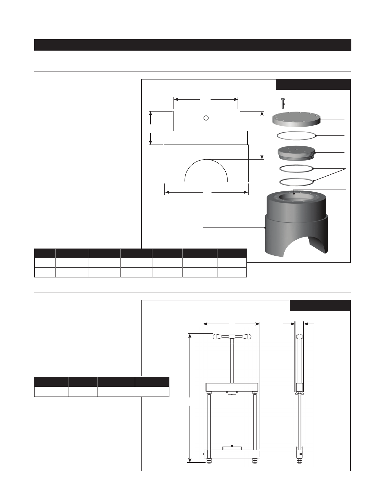
1. Electrofusion Fitting
Each tting is composed of:
• Electrofusion housing with metal
bushing.
• Completion plug with two O-rings.
• Completion cap with one O-ring.
NOTE: These ttings are
compatible with any universal
processor available on the market
equipped with a barcode pen /
scanner.
B
Ø1
Electrical Parameters
• Input voltage 220 V (180 – 240 V)
• Frequency of power supply current
50 Hz
• Output voltage 8 V – 48 V
• Power 3.5 KW
Ø
Electrofusion Fitting
DIMENSIONS – Inches (mm)
PE PIPE Ø Ø1 A B WT – lbs (kg) Turns*
8" 13.00 (330) 9.76 (248) 7.59 (193) 5.62 (143) 103.6 (47)
12" 17.71 (450) 12.75 (324) 9.44 (240) 6.29 (160) 194.0 (88)
41/4 ± 1/4
31/4 ± 1/4
eleCtrofusion fitting
Hex-Head Screw
A
Completion
*Number of revolutions to install
completion plug
Flange
O-ring
Plug
O-rings
Metal
Bushing
2. Centering Clamp for
Electrofusion Fittings
The Centering Clamp is used to
properly align the Electrofusion
Fittings to the pipe during the
fusion process. It is designed to
evenly distribute the clamping
force applied by the operator.
DIMENSIONS – Inches (mm)
L W H WT – lbs (Kg)
21.65 (550) 2.75 (70) 48.54 (1233) 46.2 (21)
Centering Clamp
L
W
H
Swivel
Holder
3
Page 4
MUELLER
®
Shur StopTM Unit 812 PE Line Stopping System
Equipment, Parts and Dimensions
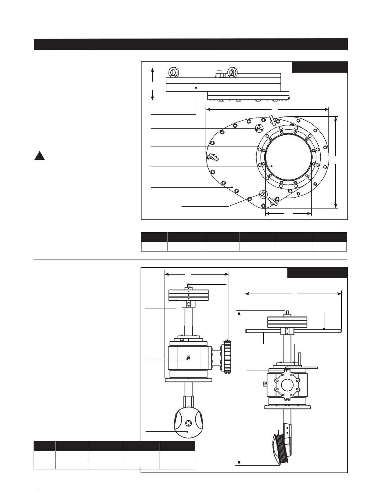
3. Slide Gate Valve
The Slide Gate Valve consists of a
sliding gate housed between two
at bodies; pressure is held rmly
by two O-rings, one above and one
underneath. The valve is tted with
an internal pressure equalizer which
allows easy opening when pressure
varies between the upper and lower
parts of the valve. To open and close
the valve, turn the operating square
approximately a quarter turn.
!
CAUTION: Never leave the
valve with the gate in the closed
position when not in use. In
the event that the gate is stuck,
loosen the screws holding the two
valve bodies, bring the gate to the
open position and retighten the
screws.
slide gate ValVe
H
Lower Valve Body
Equalization Valve
Upper Flange
Gate
Upper Valve Body
Operating Square
L
Lower
Flange
W
A
DIMENSIONS – Inches (mm)
PE PIPE L W H PASSAGE ØA WT – lbs (Kg)
8" – 12" 29.23 (742.5) 21.81 (554) 8.00 (203.5) 10.90 (277) 172.0 (78)
4. Stopping Machine
The Stopping Machine is composed
W
Operating Square
of:
• A stopping machine with bypass
valve, bleed valve and available gas
Weights
source (equalizer);
• An expanding stopper consisting of
two anges.
On the upper part of the stopping
bar there is an operating square that
when turned (clockwise) the two
Bleed
Valve
anges compress resulting in the
expansion of the sealing ring.
The result is full contact between the
sealing ring and the inner wall of the
pipe, ensuring complete gas control
The affect is 100% stop off.
Stopper
DIMENSIONS – Inches (mm)
PE PIPE L W H WT – lbs (Kg)
8" 23.42 (595) 16.92 (430) 41.92 (1065) 240.3 (109)
12" 31.96 (812) 19.29 (490) 54.25 (1378) 481.6 (218)
stopping maChine
L
Long Handle
Safety Ring
Short Handle
Bypass
Throttle
H
Sealing Ring
4
Page 5
MUELLER
®
Shur StopTM Unit 812 PE Line Stopping System
Equipment, Parts and Dimensions
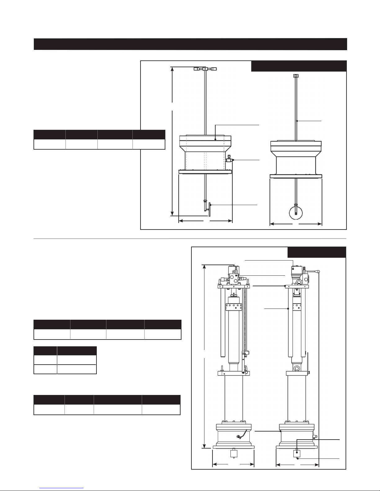
5. Cleaning / Inspection Machine
This device is used to allow cleaning
of the pipe in which the stopper will
be working. It also allows inspection
of the ttings internal threads
and cleaning if necessary before
installing completion plug.
DIMENSIONS – Inches (mm)
L W H WT – lbs (Kg)
15.55 (395) 15.31 (389) 46.81 (1189) 610.6 (27)
Cleaning / inspeCtion maChine
H
Viewer (inside)
Bleed
Valve
Brush
L
Rod
W
6. Drilling / Completion Machine
The Drilling Machine allows tapping
operations through Shur-Stop 8" and
12" PE ttings. Specially designed
cutters recover virtually all shavings
and are equipped with pilot bit for
coupon retention.
DIMENSIONS – Inches (mm)
L ØW H WT – lbs (Kg)
16.14 (410) 15.31 (389) 68.34 (1736) 418.8 (190)
PE PIPE HOLE Ø
8" 6.88 (175)
12" 9.25 (235)
SCOPE OF MACHINE
MACHINE M.O.P (psi) AMBIENT TEMP. (°F) PIPE MATERIAL
Standard 125 -4/+122 Polyethylene
Hydraulic Motor
Hydraulic
Distributor
Motor Support
Guiding
Columns
drilling maChine
H
Drilling
Bell
Shell
Cutter
Pilot
Bit
ØW
L
5
Page 6

MAChiNe Use
MUELLER
®
Shur StopTM Unit 812 PE Line Stopping System
Operating Instructions
ASSEMBLY AND USE
1. Position the electrofusion tting
on the pipe. Remove the completion
plug O-rings and thread completion
plug into tting (A.).
Internal Plug
Electrofusion
Fitting
A.
2. Position the Centering Clamp over
the tting with the lower plate open
(B.) centering the pin on the central
hole of the completion plug (B1.) and
close the lower plate (B2.).
Positioner
Lower
Plate
3. Align the pipe holder to the axis of
the pipe (C.).
Pipe Holder
C.
4. At this point rotate the screw of the
centering clamp until the pipe holder
is in contact with the pipe (D. & D1).
!
CAUTION: The best
compression is the one where it
is impossible to insert a sheet of
paper between the fitting and the
pipe.
5. Perform the electrofusion
referring to the technical data
shown on page 3 and fitting
barcode.
6. Allow sufficient time for cooling.
7. Turn the screw of the centering
clamp counter-clockwise (e.).
e.
8. Turn the lower plate and remove
the centering clamp (F. & F1.).
B.
B1.
B2.
Pin
Central
Hole
D.
D1.
Screw
F.
F1.
9. Unscrew the completion plug,
thoroughly clean the seat and insert
the sealing O-ring lubricating it with
PURITY-FG Spray or equivalent.
6 7
Page 7

MUELLER
®
Shur StopTM Unit 812 PE Line Stopping System
Operating Instructions
10. Install the appropriate vent /
purge fittings as required by
company practice (G. & G1).
11. Allow sufficient time for cooling.
PE Pipe 8"– 12"
G.
G1.
Slide
Gate
Valve
12. Prepare the slide gate valve with
the lower ring of suitable diameter
and attach to the electrofusion fitting
(h.).
Vent Fitting
20"
Eyebolt
Adjustment Flange
Combined Wrench
Preparation of Drilling Machine
1. Remove the machine body from
the metal box.
2. Attach the pilot bit with the shell
cutter arbor (A. & A1.).
Pilot Bit
A.
Allen Key for
tightening
A1.
3. Attach shell cutter to arbor (B.).
4. Retract boring bar until shell cutter
is fully inside machine housing.
h.
Shell
Cutter
B.
7
Page 8

MUELLER
®
Shur StopTM Unit 812 PE Line Stopping System
Operating Instructions
5. Lift and position the drilling
machine onto the slide gate valve in
the open position. Tighten the bolts
in a criss-cross fashion (C.).
CAUTION: After each opening
!
and closing of the valve, remove
the operating wrench to prevent
accidental movement.
8. Remove the handles.
9. Position the motor support onto
the boring bar operating square.
Ensure guide columns are lined up
with housings (D.).
Bushing with
Control Screw
Motor
Support
Guiding
Columns
Graduated
Scale
Collar
D.
Anti-
Slide
Pin
e.
11. Start the hydraulic control unit.
12. Turn the hydraulic distributor
lever clockwise (G.).
13. Insert the removable handle in
the drilling machine.
Lever turned
90° clockwise:
shaft turns
clockwise
C.
6. Insert the removable handles
7. Lower the shell cutter to the pipe
by using the removable handles
placed on the head of the drilling
machine, turning them clockwise
until contact is made with the
pilot drill on the pipe. When this
occurs, turn the feed tube a quarter
turn counter-clockwise to avoid
jamming when drilling begins.
NOTE: There is an opening at the
very top of the shaft. This is to
allow the insertion of a pin, which
ensures that the motor support
bushing does not slide out (e.).
10. Connect the hoses coming from
the hydraulic control unit to the quick
couplings of the hydraulic operator
ensuring the lever is in the neutral
position (F.).
Lever in Neutral Position:
Shaft Stopped
Pipe coming
from Hydraulic
Control Unit
F.
G.
Hydraulic
Distributor
Pipe coming
from Hydraulic
Control Unit
8
Page 9

MUELLER
®
Shur StopTM Unit 812 PE Line Stopping System
Operating Instructions
14. Use the removable handle,
turning it clockwise to begin drilling
(h.)
Advancement
of the shell
cutter,
adjusted using
the removable
handle
h.
15. When the removable handle
comes into contact with the guiding
column insert the second handle
into the previous openings and
simultaneously slide out the rst one.
Continue in this way until the drilling
is complete.
16. When the cutter shell makes
contact with the pipe, turn off the
hydraulic operator and stop drilling.
17. Loosen the knob on the
graduated scale.
18. Turn the graduated scale 90°
clockwise.
19. Then turn the knob on the
graduated scale until it is tight (i.)
Graduated
Scale
Knob
i.
Collar
20. Loosen the collar using the knob.
21. Move the collar down to bring
the lower part (indicated by the tip
of the arrow) in correspondence to
the line below the diameter of the
pipe on which the operation is being
carried out (J.).
Collar
J.
22. Loosen the knob on the
graduated scale, turn the graduated
scale 90° counter-clockwise and
then tighten the knob (K.).
23. Open the oil ow and begin
drilling again, until the pipe coupon
detaches. The location of the collar
indicates the farthest travel the
machine can be operated safely,
without contacting the bottom of the
pipe.
24. Return the hydraulic distributor
lever to the neutral position (L.)
Lever in
Neutral
L.
25. Turn off the hydraulic power and
turn off the hydraulic control unit.
26. Remove the removable handle.
27. Turn the feed screw counterclockwise until the shell cutter is
inside of the drilling bell.
28. Close the slide gate valve.
29. Attach relief piping (M.).
Bleed Valve
Flexible Pipe
Graduated
Scale
Knob
K.
M.
30. Purge the residual pressure
above the closed gate a suitable
distance from possible sources of
ignition.
31. Remove hoses from the
hydraulic control unit and operator.
32. Remove the drilling machine.
9
Page 10

MUELLER
®
Shur StopTM Unit 812 PE Line Stopping System
Operating Instructions
33. Carry out the cleaning operation
using the cleaning inspection
machine equipped with nylon wire
brush (N.).
Cleaning /
Inspection
Machine
with
Viewer
Brush
N.
34. Proceed with stopping operation.
35. Check the operation of the
expanding stopper. If the sealing
ring does not expand evenly on
the entire perimeter, it is necessary
to lubricate the walls surrounding
the ring with PURITY-FG Spray or
equivalent (walls are compressed
by two steel anges). Expand and
retract the sealing ring a few times
until the expansion is uniform. In the
event that the stopper is not used
for a long time, it is recommended to
completely disassemble the stopper,
replace the sealing ring and lubricate
thoroughly. After reassembling the
stopper, wipe the outer side of the
ring that comes into contact with the
inner side of the pipe.
36. Clean and lubricate the stopper
bar and the sealing disk to provide
smooth operation and to allow
centering of the stopper during the
expansion phase.
37. Position the stopping machine
(O.) on the slide gate valve.
NOTE: There are 2 handles on the
stopping machine. The longer one
should always be on the upstream
side.
Long Handle
Short
Handle
!
O.
38. Perform the same operations
on the second tting and install the
bypass between the two machines.
Equalize the pressure (P.) of the rst
slide gate valve. For this operation
rotate the knob that controls
equalizing valve counter-clockwise
until it stops.
39. Open the slide gate valve.
40. Open the machine bypass.
41. Open the machine bypass
located on the second stopping
machine.
Counterclockwise
P.
Equalization Valve
10 11
42. Purge the air in the bypass
through the drain valve located on
the downstream stopping machine.
43. Open the second slide gate
valve without acting on the internal
pressure equalizer, as pressure is
already equal above and below the
gate.
44. Ensure the proper operation of
the bypass and check for leaks.
45. Leaving the safety ring loose,
lower the stopper and position the
long handle between the pins on the
saftey ring. If this is difcult, repeat
previous step taking care to ensure
the plug is at a 90° position with
respect to the pipe axis. Once the
hole has been passed, place the
plug in the direction of the pipe axis.
CAUTION: The plug should
!
never be inserted and expanded
on the upstream side.
46. Turn the ratchet handle
clockwise and gradually expand the
sealing ring of the stopper. During
this operation slide the rod from top
to bottom and vice versa to properly
position the stopper in the pipe (Q.).
Long Handle
Short
Handle
Q.
47. Expand the sealing ring to
obtain a positive shut-off. DO NOT
overtighten.
!
CAUTION: The torque applied
to the ratchet spanner should not
exceed 52 ft-lb for the 8" plug.
The torque applied to the ratchet
spanner should not exceed 74 ft-lb
for the 12" plug.
Page 11

®
MUELLER
Shur StopTM Unit 812 PE Line Stopping System
48. If leakage occurs between the
stopper bar and the sealing disk
gradually tighten the Allen screws.
49. Repeat the same operations on
the second stopper machine.
50. Purge remaining gas through No.
1 and No. 2 (r.).
51. Tighten the safety ring.
52. Make the repairs.
53. Before decompressing the
sealing ring, it is necessary to
equalize the pressure upstream and
downstream of the same stopper (s.).
When only gas comes out of the vent
No. 2, close the respective gate valve
letting the gas equalize pressure.
It is now possible to test the new
connections (T.).
54. Decompress the sealing ring of
the stopper by operating counter-
clockwise on the ratchet handle until
a hard stop and retract the stopper
inside the stopping machine.
55. Repeat the same operations on
the second stopping machine (U.).
56. Close the related slide gate
valves.
57. Bleed the gas contained in the
bypass at a suitable distance from
possible sources of ignition (v.).
Operating Instructions
No. 2
No. 1
r.
Vent Open for Purging
Hose
No. 2
No. 1
s.
Vent Closed
No. 2
No. 1
T.
Bleed Valve
v.
58. Remove the bypass and the
stopping machines (w.).
Vent Closed
No. 2
No. 1
U.
No. 2
No. 1
w.
11
Page 12

MUELLER
®
Shur StopTM Unit 812 PE Line Stopping System
Operating Instructions
Preparation of Drilling Machine
To Insert Completion Plug
1. Attach completion plug holder
support to the drilling machine shaft
(A. & A1.).
Plug Holder
Support
A.
Allen Key to
Tighten Allen
Screws
A1.
Allen Screws
2. Place the plug holder ange on
the completion plug and attach it
with the provided screws (B.).
3. Attach the inserting tool and plug
onto the plug holder support and
tighten the spring detents (C.).
Screwdriver
to tighten
the Spring
Detents
Spring
Detents
C.
4. Lubricate the O-ring of the internal
plug with PURITY-FG Spray or
equivalent and retract the plug into
the machine adapter.
5. Assemble the completion machine
on the slide gate valve, open the
equalization valve and then open the
slide gate valve.
6. Turn the feed screw clockwise
and move the completion plug
towards the tting.
7. Install the ratchet handle (D.).
10. Remove the ratchet and turn the
feed screw of the machine counterclockwise until the shaft is released
from the plug holder support.
11. Remove the completion
machine, the slide gate valve and
the plug holder support (e.).
Internal Plug
e.
12. Install completion cap (F.).
Completion Cap
F.
Allen Key for tightening
Allen Screws
Plug Holder
Flange
B.
Completion
Plug
3
/4ʺ Ratchet
Spanner
D.
8. Fully tighten the completion plug,
taking care to SIMULTANEOUSLY
turn both the ratchet and the lead
screw clockwise.
9. Bleed any residual pressure off
using the bleed valve (see point 38
on page 9) and check the completion
plug for leaks.
12
Page 13

®
MUELLER
Shur StopTM Unit 812 PE Line Stopping System
Diagnostics / Storage
TrOUBLeshOOTiNG
proBlem Cause solution
Drilling time too long Worn cutter Replace the cutter.
Gas leakage between the
drilling shaft and the screw Worn O-rings Replace the O-rings.
Inadequate sealing of the stopper No lubrication performed on the With PURITY-FG Spray or equivalent
angled walls of the sealing ring lubricate the angled walls of the
sealing ring expanding and retracting
it completely.
No lubrication performed on the Lubricate the sealing disk with
sealing disk of the plug bell PURITY-FG Spray or equivalent.
Presence of residue on the bottom Clean again using the
of the pipe inspection / cleaning machine.
Inadequate sealing of the Insufcient tightening of the screws
sealing disk of the ange that compresses the Tighten the screws slightly.
sealing disk
Inadequate sealing of the valve Equalization valve not closed Close the equalization valve.
Residues on the sealing O-ring Replace the O-rings before the
next use.
sTOrAGe
In case of long periods of inactivity,
the equipment must be stored taking
suitable precautions for the place it
is stored in and the duration of the
storage:
• Store the equipment in a closed
place.
• Protect the equipment from
humidity and extreme temperature
changes.
• Prevent corrosive substance
from coming into contact with the
equipment.
13
Page 14

MUELLER
®
Shur StopTM Unit 812 PE Line Stopping System
Notes
14
Page 15

MUELLER
®
Shur StopTM Unit 812 PE Line Stopping System
Notes
15
Page 16

Gas (North America)
1.800.798.3131
Reliable Connections
Copyright © 2018 Mueller Co., LLC. All Rights Reserved.
The trademarks, logos and service marks displayed in this document herein are the property of Mueller Co., LLC, its afliates or other third parties.
Products marked with a section symbol ( § ) are subject to patents or patent applications. For details, visit www.mwppat.com. These products are
intended for use in potable water applications. Please contact your Mueller Sales or Customer Service Representative concerning any other application(s).
TM
www.muellergas.com
moreinfo@muellercompany.com
Form 13933 – 11/18
 Loading...