

Page 1

These instructions apply to this sleeve when used with
Mueller mechanical joint cut-in valve.
Use this Gasket on the spigot (opposite) end of sleeve –
Set other side of tag.
Take one gasket from cut-in valve – Use it in this end.
Instructions below.
This sleeve and valve t two diameters of cast iron
pipe, using two diameters of End Gaskets. Be sure
End Gaskets with Cut-in Valve are right for the outside
diameter of your existing piping or main. See information
in end of valve.
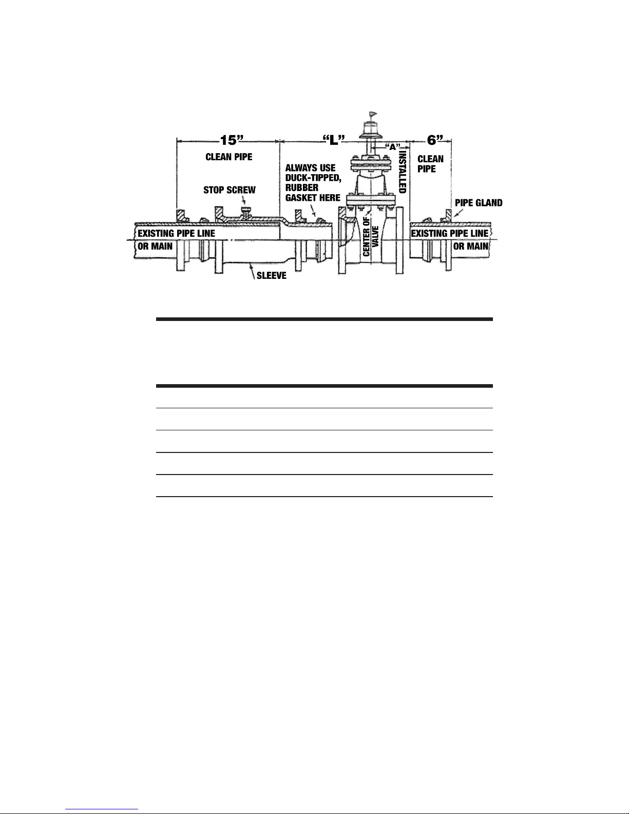
Determine location of valve on main by dimen. “A” in
table on other side of tag. Measure and mark o
dimension “L” from the table and clean pipe thoroughly
as shown. This can be done best before cutting the
main. First shut o main, then cut o “L” length of pipe
(as shown in table) out of the main. Slide the Pipe Glands
and End Gaskets, taken from Valve, over each end of
cut main. Back Stop Screw in sleeve out 3/4” and slide
sleeve over main. Slide a Pipe Gland and a duck-tipped,
rubber End Gasket over sleeve spigot. Position valve on
end of main. Slide sleeve spigot in end of valve. Screw
stop screw into sleeve with a wrench until tight. Position
all three end gaskets and pipe glands. Gaskets wetted
with a soapy water solution install more easily. Install
all gland bolts and with wrench, tighten alternately
(180° apart) until all are evenly tight. 90ft. lbs. max.
torque. Open cut-in valve. Installation is complete.
Turn on pressure in main.
Installation Instructions
MJ Cut-In
Valve
(continued)
Page 2
By deviating from the above listed instructions, you will void any product
warranty and release Mueller Co. and its aliated entities from any and all
liability associated with the installation or use of this product. For details
on the product’s warranty, terms, and conditions, please visit
www.muellercompany.com.
Phone: (800) 423-1323
© 2018 Mueller Co., LLC. All rights reserved.
Form 9035 01/18
Installation Instructions (continued)
“L”
A = End of
Pipe to
Center of
Valve
Cut 18-1/4” Out of 4” More For 4” Valve & Sleeve 2”
20” “ “ 6” “ “ 6” “ “ “ 3”
20-1/2” “ “ 8” “ “ 8” “ “ “ 3”
22-1/4” “ “ 10” “ “ 10” “ “ “ 4”
23” “ “ 12” “ “ 12” “ “ “ 4”
 Loading...