

Page 1
operating instructions manual
HYDRO-GUARD
TABLE OF CONTENTS PAGE
®
Remote
Pressure
Monitoring
System
2.1.1
Installation and Site Evaluation 2-3
Installation and Operating Instructions 4
Operating Instructions 4-11
Battery Replacement and Technical 12
Troubleshooting and FAQ 13
Parts 14
Notes 15
!
WARNING:
Failure to read and follow the instructions contained within this manual
could result in serious personal injury, and/or damage to the Remote
Pressure Monitoring System.
1. Each person involved in the assembly, installation and/or maintenance
of the Hydro-Guard Remote Pressure Monitoring System must read
this manual carefully and follow all instructions prior to performing any
installation or maintenance procedures involving the Unit.
2. Be sure the corporation valve or other isolation valve is closed prior to
installation or removal of the pressure sensor.
3. Always use all necessary safety equipment and follow all recommended
procedures when installing, operating and maintaining the Hydro-Guard
Remote Pressure Monitoring System.
!
CAUTION:
When installing the Remote Pressure Monitoring System, ensure the known
pressure is less than 250psi. If pressure may exceed 250psi at identied
installation site, contact Mueller Co. for proper conguration.
Reliable Connections
Customer Service Center
Decatur, Illinois
800.423.1323
www.muellercompany.com/hydro-guard
moreinfo@muellercompany.com
The content of this manual is the sole and exclusive property of Mueller Co.
Unauthorized distribution or reproduction strictly prohibited.
TM
Page 2

General
HYDRO-GUARD
®
Remote Pressure Monitoring System
Installation and Site Evaluation
Each Remote Pressure Monitoring
System, consists of an RTU and
Sensor, (here-by known as Device).
Prior to the installation of the Device,
strategic installation points should be
identied. Conrmation of a cellular
signal (Verizon or AT&T) is available
at the identied site. Contact Mueller
Co. for additional support if required.
When installing the Remote Pressure Monitoring System with a valve
box into the distribution network,
identify the OD and type of pipe as
well as the depth requirement prior
to ordering. Mueller Co. can assist
in verifying that the proper saddle
and valve box can be supplied.
The Remote Pressure Monitoring
System lid-mounted antenna shall
be installed no more than six (6)
inches below-grade to ensure the
cellular communication signal is not
impeded.
GPS Location Considerations
Each Device contains a cellular
modem and GPS locator. Some
obstacles can interfere with the
signals required for each of these
to operate properly. Conrmation
of cellular signal can be obtained
with a standard cell phone. If GPS
is unavailable, the location of the
Device can be entered manually
into the software. Address or
GPS coordinates should be noted
upon installation. To obtain GPS
coordinates (longitude and latitude
coordinates), it is recommended that
you utilize a GPS location APP or
website. Enter the nearest physical
street address to the site where the
Device will be located into a GPS
coordinate APP or website to obtain
the GPS coordinates. Upon obtaining
the information, enter the longitude
and latitude coordinates into the
Device Management website. Log
into account and open the Device
which is to be mapped. Select “Edit”
and enter longitude and latitude
coordinates in the appropriate elds.
Shipping
The Remote Pressure Monitoring
System is powered by a series
of lithium batteries. Specic and
approved shipping procedures must
be observed. The Remote Pressure
Monitoring System may be shipped
with or without a valve box and
ancillary items depending on the
customer’s desired installation. In
the event of the unit being returned
for service, contact Mueller Co.
Customer Service for approved
shipping and handling information.
NOTE: The RTU can only be
shipped via ground transportation
and must be properly labeled
to identify presence of lithium
batteries. Contact Mueller Co. at
877.864.8500 before shipping.
InstallatIon
Installation in a Valve Box
1. Remove the Remote Pressure
Monitor from its packaging and
inspect for possible damage during
shipping.
2. Once service saddle installation
is complete, install guide plate
(P/N: 147506P) over the service
saddle and apply suitable sealant
or joint tape to the inlet side of the
corporation valve before installing
into the saddle. Thread the
corporation valve into the service
saddle as shown (see page 3). The
guide plate will center the valve box
bell end over the service saddle and
corporation valve.
NOTE: Before drilling, ensure
guide plate is in between the
service saddle and corporation
valve (see page 3).
3. Perform the drilling operation
adhering to the following operating
instructions for the particular Mueller
Co. Drilling Machine being utilized:
• D-5/E-5: Form 9335
• Mega-Cut: Form 12092
• Tru-Cut: Form 11941
• PL-2: Form 10292
Mode Normal
Request maintenance mode
Status Critical High
Latitude 35.0757516666667
Longitude -85.1868716666666
Uploads per Day 0
ICCID 8901 1704 2580 2049 4799
2
Page 3
HYDRO-GUARD
®
Remote Pressure Monitoring System
Installation
4. After the drilling operation is
complete and corporation valve is
closed, apply a suitable sealant or
joint sealing tape on the inlet side
of the ¾” threads on the supplied
bushing. Securely attach the ¾” end
of the bushing to the outlet of the
corporation valve.
NOTE: Avoid use of excessive
sealant. Avoid contact with sensor
transducer tip.
5. Securely attach the pressure
sensor to the ¼” end of the bushing.
Utilize a suitable sealant or joint
sealing tape on the inlet threads
of the pressure sensor to ensure a
proper seal.
NOTE: Avoid use of excessive
sealant. Avoid contact with sensor
transducer tip.
6. Prior to installation of pressure
sensor dry the interior of the
corporation stop threaded
connection.
7. Once the sensor has been
attached, turn the corporation valve
to the “open” position. Run sensor
cable through composite valve box
when installing pressure sensor.
Refer to the installation instructions
®
for the Mueller
composite valve box
(Form MC014).
NOTE: When paving and
compacting asphalt, use a Mueller
iron lid (P/N: AJBV-4CWATER)
to prevent damage to the RTU.
Once asphalt work is completed,
replace iron lid with the RTU. Be
sure the sensor tip is exposed to
line pressure prior to connecting
the sensor cable to the RTU.
8. Once the corporation stop has
been opened and pressurized,
plug the male end of the multi-pin
connector of the sensor cable into
the mated connector of the RTU
(located on bottom of RTU).
9. Once the RTU and cable are
connected, insert the RTU into the
ductile iron top section.
NOTE: Be certain that the lid of
the RTU is mounted ush with the
surface of the ductile iron valve
box top section.
10. The pressure monitor will begin
operating once the sensor cable
is plugged into the RTU and the
pressure sensor is exposed to line
pressure. The rst reading may take
up to 24 hours to be transmitted to
the website. The Device will reveal
system pressures with no additional
inputs. In order to customize
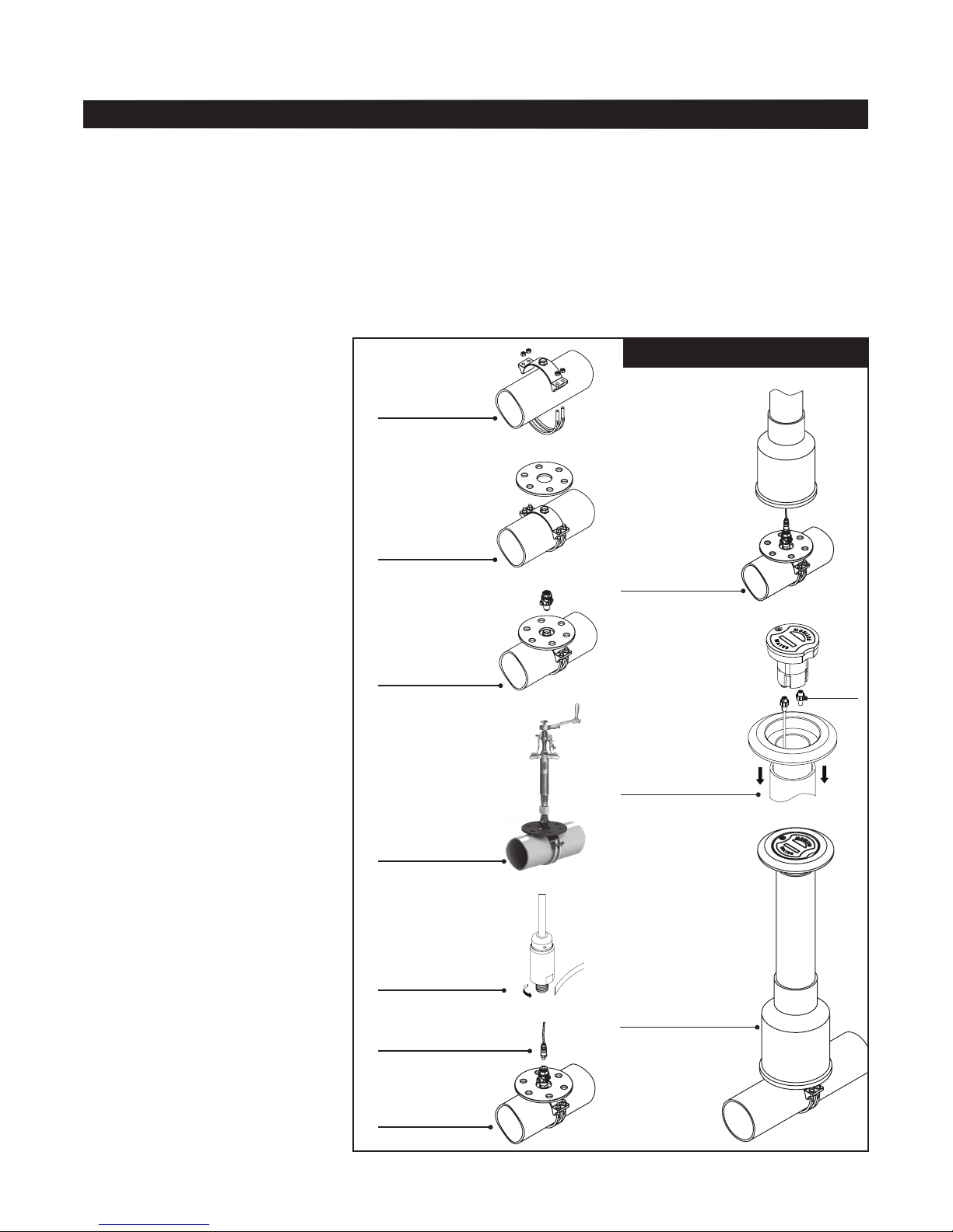
A. Install service
saddle.
B. Install guide
plate.
C. Thread corporation
valve into service
saddle. Valve should
be open.
D. Perform drilling
operation.
E. Apply joint-sealing
tape to threads of
pressure sensor.
F. Dry interior of
threaded connection of
corporation stop.
G. Thread pressure
sensor into
corporation valve.
Open valve.
pressure level notications, the
following four (4) values may be
set on the measurements screen:
Warning High, Warning Low, Critical
High, and Critical Low. Entering the
above mentioned inputs into the
system is described in the “Getting
Started” on page 4.
H. Install valve box
over the assembly.
I. First, ensure
waterproof plug is
plugged in. Install
adjustable top into valve
box. Plug sensor cable
into Black connector on
RTU and hand tighten
connector. Insert RTU
into adjustable top.
Carefully back ll and
pave area around valve
box per direction by
engineer of record.
J. Installation complete.
Ready for pressure
monitoring. Log onto
www.miwwt.net to view
data.
§
Page 4
HYDRO-GUARD
®
Remote Pressure Monitoring System
Installation and Operating Instructions
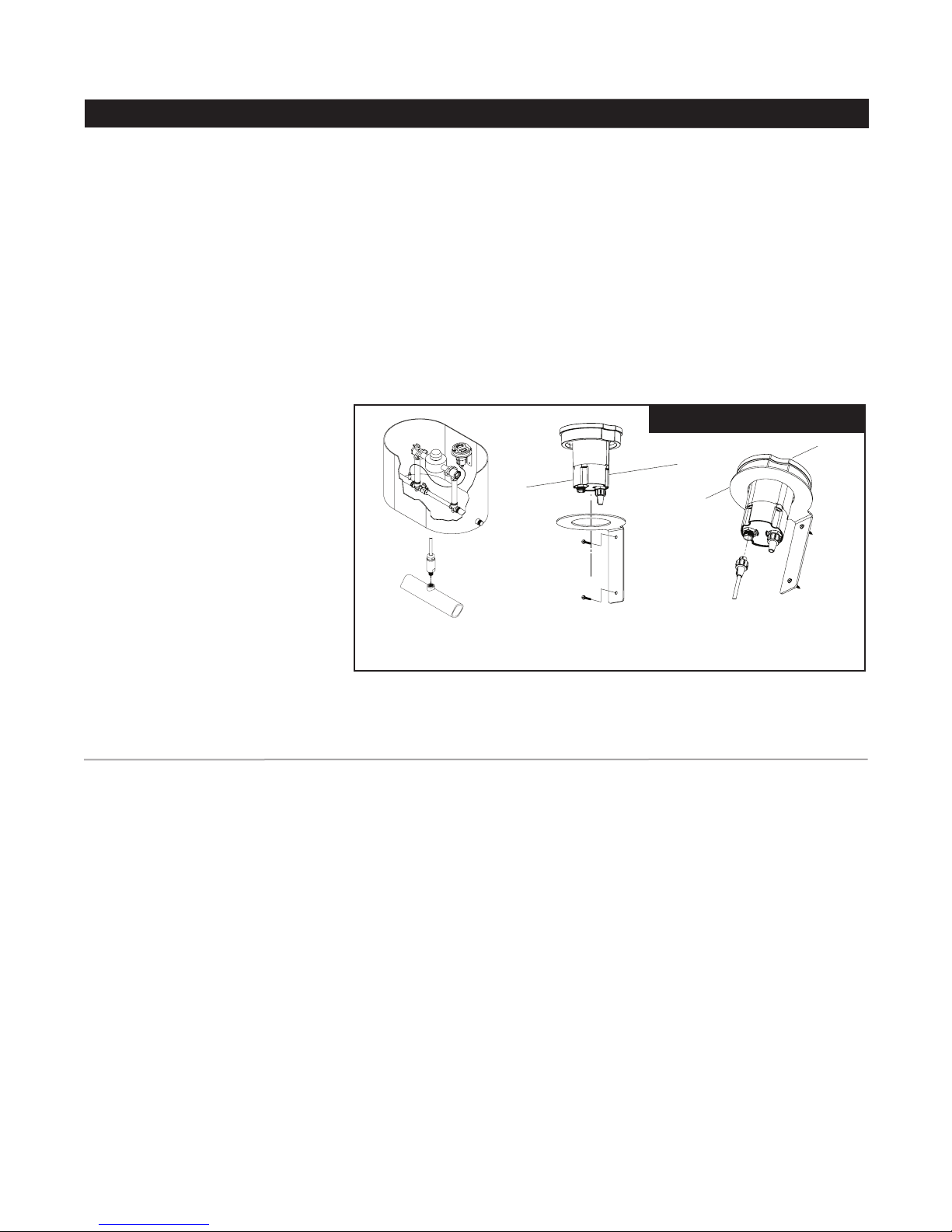
Installation in a Meter Box, Vault,
or other Structure
1. Remove the Device from its
packaging and inspect for possible
damage during shipping.
2. Apply sealant or joint tape to
pressure sensor and thread into
available ¼” NPT port.
NOTE: Avoid use of excessive
sealant. Avoid contact with sensor
transducer tip.
3. Install supplied mounting bracket
onto setter or to side wall of meter
vault no more than 6 inches
below grade to ensure the cellular
communication signal is capable of
transmitting and receiving data.
4. Be sure sensor tip is exposed to
line pressure prior to connecting
the sensor cable to the RTU.
Connect the sensor cable to the
RTU connection port located on
the bottom side of the RTU. The
pressure monitor will begin operating
once the sensor cable is plugged
into the RTU and the pressure
sensor is exposed to line pressure.
The rst reading may take up to
24 hours to be transmitted to the
website. The Device will reveal
system pressures with no additional
inputs. In order to customize
pressure level notications, the
following four (4) values may be
set on the measurements screen:
Warning High, Warning Low, Critical
High, and Critical Low. Entering the
above mentioned inputs into the
A. Apply joint-sealant and
thread pressure sensor into
NPT port. Turn on the water.
B. Install mounting
1
bracket to wall of meter
/4”
box/vault.
system is described in the “Getting
Started” below.
NOTES: For best communication
performance RTU must be
installed vertically with the ange
facing up.
Composite lids must be utilized in
vaults or boxes to ensure cellular
communication, unless a suitably
sized hole is cut into a cast iron
lid that will allow the composite
lid to be mounted in the vault
cover.
C. Plug sensor cable into
Black connector on RTU
and hand tighten connector.
operatIon and system monItorInG
Getting Started
The Device will begin logging data
once the sensor cable is plugged
into the Remote Terminal Unit (RTU);
however pressure readings may take
up to 24 hours to be transmitted to
the website. The Device will reveal
system pressures with no additional
inputs. Up to four (4) customizable
values can be entered into the web
based control panel (Warning High,
Warning Low, Critical High, and
Critical Low).
Upon entering the client’s order,a
Mueller Customer Service Specialist
will send an administrative email to
the client administrator (end user)
identied on the order form. The
email will contain a web link that will
direct the client administrator to the
Device registration web page. The
Registration web page will allow
the client administrator to enter a
password; select how the system
shall send event notications (i.e.,
SMS-text messaging, email – both,
or none); and time zone settings.
NOTE: The Hydro-Guard
Monitoring System registration
email invitation will be sent from
NOREPLY@MIWT.NET. In the event
the customer does not receive
an invitation email, please check
spam folders for the receipt.
Some servers will block the
message as spam until unblocked
by the client. Suggestion: To
ensure the email is received
please email Mueller Co. at
NOREPLY@MIWT.NET upon the
placement of your order.
Once registered, users may log into
the Mueller secure web page via the
address: miwt.net. Once logged into
the system, registered users can
customize their management prole
by selecting the “Edit Prole” tab on
the top navigation bar.
4
Page 5
HYDRO-GUARD
®
Remote Pressure Monitoring System
Operating Instructions
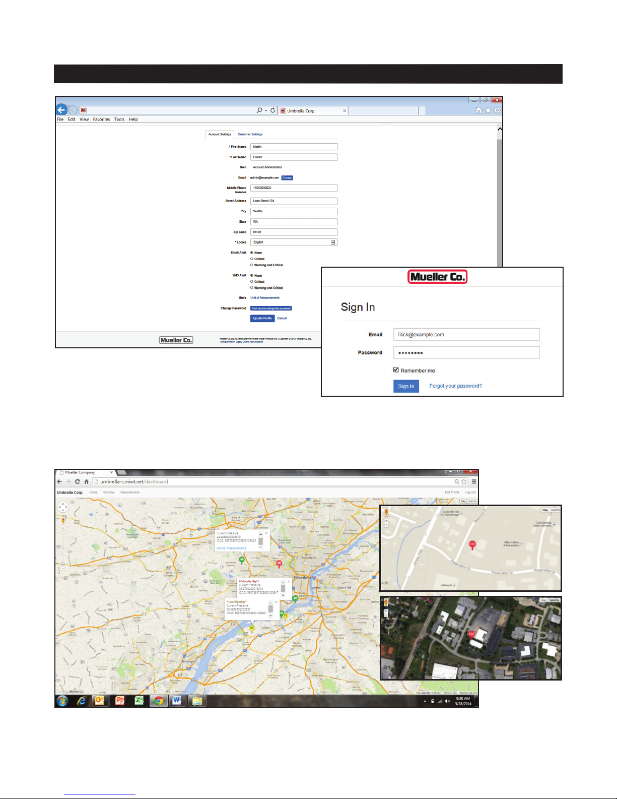
REGISTRATION PAGE: This page will allow the
client administrator to enter a password; select how
the system shall send event notifications (i.e., SMStext messaging, email – both, or none); and time zone
settings. Once registered, users may log into the
Mueller secure web page via the address: miwt.net.
SIGN IN PAGE: Once registered, users may access
current and historical pressure readings and view
trending graphs by logging onto the system via the Sign
In screen.
HOME PAGE: Once signed into the “Device’s” home page an installation location map will appear. All pressure moni-
tored locations within a client’s distribution network will be viewable on the customer’s secure website and interactive online
map. To view measurements or to edit settings for a specific monitored location click the associated icon on the map.
5
Page 6

HYDRO-GUARD
®
Remote Pressure Monitoring System
Operating Instructions
EDIT PAGE: From the “Edit Device” menu the viewer can select any existing Device to be edited. Selecting the “Edit”
tab will advance the viewer to the edit screen where the viewer can view or customize the “Device’s” management and
sampling parameters. On the administrator screen (above), the customer can enter or change alert levels.
• Data Upload/CONNECT function:
The Hydro-Guard
Monitoring System has been preprogrammed for one data upload
per day (default). This setting can
be modied to upload data weekly,
daily, or up to 24 times per day. To
modify the number of data uploads
open the Device SETTINGS web
page and locate the calendar
application at the lower section of
the management screen. Using the
blue PLUS button, open the drop
down navigation. Select CONNECT
to select the date(s) and time(s) to
initiate a data upload.
®
Pressure
• MAINTENANCE function: The
Hydro-Guard® Pressure Monitoring
System allows for the scheduling of
an immediate response log report,
referenced as the MAINTENANCE
mode. This mode can be scheduled
or operated on an “as needed”
basis.
• TRANSIENT MONITORING
function: The Hydro-Guard
Pressure Monitoring System has
the ability to monitor for transient
pressures (up to 256 readings per
second). This function must be
scheduled. To schedule a transient
monitoring session open the Device
®
SETTINGS web page and locate
the calendar application at the lower
section of the management screen.
Using the blue PLUS button,
open the drop down navigation.
Select PRESSURE-TRANSIENT
CAPTURE. The select the date(s)
and time(s) to schedule the Device
to measure and log transient activity.
!
WARNING: Operating in
the PRESSURE-TRANSIENT
CAPTURE mode for more than
thirty (30) days during the life
of the Device can reduce the
Device’s overall battery life.
Page 7

HYDRO-GUARD
descrIptIon of the setup
®
Remote Pressure Monitoring System
Operating Instructions
• Phone Number: The phone
number associated with the
individual RTU is located on the
bottom of the unit.
• Description: Customers notes for
the particular site.
• Latitude and Longitude: GPS
location of the unit is automatically
determined when the Device is
installed. In the event the GPS
signal is obstructed and unable to
locate the Device, the installer can
manually enter the location on the
MIWT website by selecting Device
in the navigation bar and locating the
proper Device. Click on the Device
to be manually located and select
“Edit” in the system management
screen to enter the longitude and
latitude of where the Device has
been deployed. To determine the
longitude and latitude of the Device,
locate the nearest street address to
the installation location. Using online
resources, locate the longitude and
latitude coordinates for the street
address used.
• High Warning and Low Warning:
Pressure level at which the customer
is notied via SMS and/or Email.
• Critical High and Critical Low:
Pressure at which the customer is
notied via SMS and/or Email.
• Elevation: For operators
interested in viewing head pressure
measurements, the Device will pull
the elevation for the installation
point from the GPS mapping system
and enter it into this management
eld. In the event the GPS is not
able to populate this management
eld the eld will be zero. A manual
entry can be made in this eld if the
management eld does not populate
automatically.
• Uploads Per Day: Number of
hours between data uploads.
Recommended value is 2 (Default
setting is 1). Once all desired
management changes have been
made complete the update by
clicking on the SAVE button.
NOTES: Alerting messages occur
when readings register above or
below Warning and Critical Values
dened by the end user. User may
dene warning levels and critical
levels for high and low pressures
using the web interface. Alerts
are sent when two consecutive
readings are above or below the
user dened levels.
Up to a 5-year battery life can be
expected when recommended
settings are utilized. Some
settings outside of the
recommended settings may
reduce expected battery life.
To access a specic Device in
a distribution network in order to
update or change settings of that
Device, navigate to the Device by
either clicking on the Device from
the HOME/MAP SETTINGS or use
the top navigation bar to navigate
to the RTU INDEX. Both paths will
allow access to the settings specic
to a Device installed in the eld.
From here the operator can update
the specic Device’s description;
longitude and latitude; number of
uploads per day; warning set points;
and scheduling for monitoring and
reporting of activity.
DEVICE PAGE: The “Device”
home page contains specific
information including location, alarm
settings, and logging intervals.
Authorized administrators or
technicians can modify the Device
settings from within the Device
page.
The “Measurements” tab opens
the data log screen which allows the
user to browse data over various
time frames for individual units.
7
Page 8

HYDRO-GUARD
MIN / MAX / AVG
Transient
Readings
®
Remote Pressure Monitoring System
Operating Instructions
MEASUREMENTS PAGE: From the Measurements page, the viewer can select a time frame to be viewed for the all
units or select units. For example, by selecting “Month” all the data collected by an identified unit in the past month is
shown on an operational curve of Pressure (psi) over that period of time. Measurements recorded today; over the past
two days; over the past week; or even those recorded over the past two years can be viewed on the Measurements page.
Data trend mapping includes minimum, maximum and averages for every hour, as well as transient state reports.
DATA LOG AND INFORMATION DOWNLOADS: Pressure measurements can be reviewed in log form. From the
Measurements page select the View Measurements tab (see highlighted area). A running log of measurements can
be viewed; notes related to the log entry can be added; and all information can be downloaded as a CSV or XLS file
for system management recordkeeping.
8
Page 9

HYDRO-GUARD
software applIcatIon upGrade
®
Remote Pressure Monitoring System
Operating Instructions
AUTOMATED DATA TRANSFER
AND LOGGING: The released
Hydro-Guard App 1.0.0 software
for the Hydro-Guard Pressure
Monitoring System allows operators
of the second generation product
to schedule data transfers from
each RTU to a designated storage
folder located on their computer or
network. To begin, start Launch of
software application and log into the
utility’s MIWT.NET account. Follow
these steps:
1. Located the settings icon (Y) and
select;
2. Click on the Hydroguard App
1.0.0 link to download the application
le to a dedicated computer(s);
3. Once the application is loaded on
the dedicated computer(s) click on
the le to unpack the zipped le;
4. Extract the software application’s
management les by clicking on
the Hydroguard App 1.0.0.exe
application;
5. Click on the EXTRACT ALL
button to open le location
preference screen.
This link will allow for the preferred
folder location to be selected—
where the Hydro-Guard Pressure
Monitoring spreadsheets will be
saved;
6. Select the preferred location for
where data should be stored;
7. Open folder to view saved data
log spreadsheets.
NOTE: 1 & 4 = Maximum; 2 & 5 = Average; 3 & 6 = Minimum.
ENHANCED TREND MAPPING: View MINIMUM, MAXIMUM and AVERAGE pressure readings for every hour on
an enhanced graphical trend map at miwt.net.
9
Page 10

®
HYDRO-GUARD
Remote Pressure Monitoring System
Operating Instructions
Mueller Tech Center Home Users Devices Measurements
Description Pressure Warning Low Critical Low Warning High Critical High
Test_Device: 3; Sensor Serial: 1419200209 56.1 1.0 2.0 175.0 180.0
PowerAnalyzer Device 4.5 1.0 2.0 262.0 270.0
Test_Device: 2; Sensor Serial: 1419200174 56.8 1.0 2.0 175.0 180.0
Test_Device: 4; Sensor Serial: 1419200230 56.2 1.0 2.0 175.0 180.0
Tim S Test Unit 112.7 20.0 40.0 80.0 100.0
Device #3 No data 20.0 25.0 180.0 200.0
Test_Device: 5 260.2 20.0 25.0 180.0 200.0
GPS Development Unit 260.1 20.0 25.0 180.0 200.0
8901 1704 2580 2049 4732 57.9 20.0 25.0 180.0 200.0
8901 1704 2580 2049 4716 57.3 20.0 25.0 180.0 200.0
8901 1704 2580 2049 4724 57.2 20.0 25.0 180.0 200.0
8901 1704 2580 2049 4708 56.9 20.0 25.0 270.0 280.0
Verizon A1 0000 42F1 6926 261.7 10.0 40.0 80.0 110.0
INSTALLING ADDITIONAL PRESSURE MONITORS: New monitoring Devices will automatically appear on the
customer web interface once installed. It may take up to 24 hours for data and location to appear after installation.
054 Timothy Blair Account Administrator tjblair@muellercompany.com 2711024610 Delete
ADDING USER ACCESS: Users may be added by the Administrator at any time using the “Invite Users” button
under the “Users” Screen shown in the image below.
View Pressure Data X X X
View RTU Settings X X X
View and Edit Personal Data X X X
Annotate Pressure Data X X
Change RTU Settings X X
Change User Privileges X
Add/Remove Users X
10
Page 11

HYDRO-GUARD
®
Remote Pressure Monitoring System
Operating Instructions
ANALYTICS: The Hydro-Guard® Monitoring System features an analytic function that allows an operator to compare
measurements against one another for enhanced distribution system management.
11
Page 12

HYDRO-GUARD
Battery replacement
®
Remote Pressure Monitoring System
Battery Replacement and Technical Information
Batteries are eld replaceable and
can be ordered through Mueller
Company. DO NOT disassemble the
RTU until the replacement batteries
have arrived with replacement
instructions included. Contact
Mueller Customer Service for safe
handling and return instructions for
used batteries.
!
WARNING: Battery must be
replaced by a qualied electrical
technician. Contact Mueller Co.
for additional support.
1. Remove ten (10) screws to
separate the battery compartment
from the antenna and micro
computer.
2. Carefully slide out the antenna
wire retainer from the battery
compartment so that the antenna
wires are free.
3. Disconnect battery lead connectors
and reconnect new battery pack
using the mated connectors on the
replacement battery. Ensure wires
are securely connected before
moving to step 4.
NOTE: Be sure to connect similar
color wires.
4. Reinsert the antenna wire retainer.
5. Reattach the ten (10) screws.
NOTE: Unit includes Lithium
batteries which should be
returned to Mueller Co. for proper
disposal. Return instructions will
be provided with replacement
parts. Contact Mueller Customer
Service for assistance.
Other Options
Optional Valve Box Lengths:
• 3’, 5’, 7’, 9’
Service Saddles:
• Bronze Double Strap (up to
200psig)
• Ductile Iron Double Strap (over
200psig)
• Bronze OD Controlled for PVCPipe
(up to 200psig)
Pressure Sensors:
• Up to 250psig
• Pressures over 250psig*
*Indicates Standard Option
§
1
2
3
4
1 Antenna and Lid
2 Battery
3 Power Wires
4 Antenna Wire Retainer
5 Micro Computer
6 Connectors
6
5
technIcal InformatIon
Battery Life: Five (5) Year minimum
when recommended settings are
utilized.
Pressure Range: 0 to 250psig.
Standard Sensor Pressure (0 to
250psig) Over Pressure: In the
event that the pressure exceeds
250psig, per the manufacturers
specication, the the overpressure
rating of the sensor is 700psig;
however, the sensor may be
damaged should pressure exceed
500psig. The RTU will only identify
pressures up to 250psig.
Operating Temperature Range:
–30°F to 150°F.
Pipe Diameter Range: ½” or larger.
Default Sampling Range: 1 sample
every 15 seconds.
Transient Pressure Monitoring:
Scheduling of transient monitoring is
available with this product. Transient
pressures will be measured at a
rate of 256 samples per second
for a scheduled period of time as
dened by the operator. Mapping
12
of transient-state data points will
be less than 256 data points. Data
mapping is dependent upon volatility
of transient activity.
Resolution: 12-bit
Accuracy: +/– 2psi (250psi sensor)
+/– 5psi (500psi sensor)
NOTE: Some settings outside of
the recommended settings may
reduce expected battery life.
Page 13

®
HYDRO-GUARD
Remote Pressure Monitoring System
trouBleshootInG and frequently asked questIons
Troubleshooting and FAQ
Troubleshooting Guide
Customer/User does not receive
acknowledgement email when new
users are set up.
Customer email system must
be able to receive email from
noreply@miwt.com. Contact your IT
department to make sure this email
address is not blocked.
Frequently Asked Questions
(FAQ’s)
Q. What is my cost of ownership?
A. The initial purchase price of
the unit includes the rst year of
cellular service and a 5 year battery.
Additional years of cellular service
and a 5 year replacement battery
may be purchased from Mueller
Company. Additional costs may
include installation of the unit by
others.
Q. Who manages my web
account?
A. The customer’s administrator who
is to be identied at the time of the
initial purchase. Customer can add
or remove administrators as desired.
Contact Mueller Customer Service if
the administrator changes.
Q. Who has access to the
website?
A. Customer administrator may
grant access to an unlimited number
of authorized users within their
organization. Roles that can be
assigned are: User, Administrator,
and Technician. These roles have
different accessibility to data.
Administrator: Administrative and
Editing Rights
Technician: Viewing and Editing
Rights
User: Viewing Rights
Q. Where is the data stored?
A. Customer specic data will be
uploaded to a secure cloud based
system that is only accessible by the
clients authorized personnel and the
Mueller system administrator.
Q. Who does the data belong to?
A. All data captured by the Device
is the sole property of the client.
Mueller does not review or analyze
data unless specically requested to
do so for technical service purposes
only.
Q. Can the data be downloaded?
A. Yes, data can be downloaded
into Microsoft™ Excel® or other
spreadsheet management software.
Q. How long is the data stored on
the web?
A. Data is stored in the cloud-
based storage for a period of two
years. Data older than two (2) years
is automatically purged from the
customer’s database.
Q. Will the pressure monitoring
system work with Mueller
Systems Monitoring Software?
A. Not currently.
Q. At what frequency should the
sensors be installed?
A. A minimum of two (2) per district
metering area (DMA) or pressure
zone.
Q. Are the Pressure Monitoring
Systems SCADA compatible?
A. When connecting any SCADA
system to an outside source it is
advisable for the system integrator
to comply with the data security
guidelines found in NIST Special
Publication 800-82 “Guide to
Industrial Control Systems (ICS)
Security. For additional information
refer to http://csrc.nist.gov
publications/nistpubs/800-82/SP800
82-nal.pdf
Q. Will the Pressure Monitor
notify of power failure?
A. Data storage is unaffected by
power failures; however, if cellular
service is interrupted or the Pressure
Monitoring System malfunctions,
data transfer will discontinue and
service may be required. Notication
of a system power failure will be
indicated by the Device’s failure to
report data.
13
Page 14

HYDRO-GUARD
®
Remote Pressure Monitoring System
Parts
1
§
2
4
3
14
5
replacement parts
1 3/8 ” Ø x 13/8” shoulder x 5/16” - 5/18” screw – SS
2 Antenna/Composite Lid
3 RTU (Remote Telemetry Unit) w/Lithium Batteries
4 AJBV-4D Ductile Iron Adjustable Top – 12” L
5 Mueller Composite Valve Box – 5 ft.*
6 Male-end Sensor Cable Connector
7 Mueller Valve Box Guide Plate
8 Sensor Cable Sub-Assembly
9 Pressure Sensor
10 ¾” NPT to ¼” NPT Reducer Bushing
11 Mueller 300 Ball Corp. Valve, ¾”
12 Bronze Service Saddle – Double Strap**
13 Mounting Bracket
14 Waterproof Plug
10
11
* Valve Box also available in 3’, 7’, and 9’ lengths.
**Bronze Slip Hinge Saddles Available for IPS & C900 PVC. If the
pressure may exceed 200psi, a ductile iron saddle should be used.
6
7
8
9
9
10
8
2
13
12
14
Page 15

HYDRO-GUARD
®
Remote Pressure Monitoring System
Notes
15
Page 16

Water (U.S.)
1.800.423.1323
Reliable Connections
Copyright © 2018 Mueller Co., LLC. All Rights Reserved. The trademarks, logos and service marks displayed in this document herein are the
property of Mueller Co., LLC, its afliates or other third parties. Products marked with a section symbol ( § ) are subject to patents or patent
applications. For details, visit www.mwppat.com. These products are intended for use in potable water applications. Please contact your Mueller
Sales or Customer Service Representative concerning any other application(s).
TM
www.muellercompany.com
moreinfo@muellercompany.com
International
1.423.490.9555
www.mueller-international.com
international@muellercompany.com
Form 12942 – Rev 10/18
 Loading...