

Page 1

Prefabricated
Steel building
inStallation Manual
Page 2

Page 3

TABLE OF CONTENTS
A. Site and Foundation Preparation
General Information................................................. 1
Squaring of Foundation..............................................2
Anchor Bolt Settings ...............................................3-4
B. Building Delivery and Storage
Unloading and Preparation of Parts for Assembly ..........................1
Unloading, Handling, and Storage of Materials ............................2
Location of Building Parts ............................................3
Care and Handling of Mueller Sheet Metal...............................4-6
C. Erection of Primary and Secondary Structural
General Information................................................. 1
Tools and Equipment Required ........................................ 2
Typical Building Parts ............................................... 3
Raising Rigid Frames ..............................................4-8
Erecting Column and Beam Endwalls ...................................9
Erecting Remaining Frames........................................10-11
Assembly of Brace Cables ..........................................12
Installation of Wind Bracing ........................................13-16
D. Insulation
Wall Insulation ....................................................1-2
Roof Insulation ...................................................3-5
E. Sheeting
Fastener Layout ...................................................1
Aligning the Girts...................................................2
Screw Alignment..................................................3-4
Installation of Wall Panels ...........................................5-9
Preparing the Eave ..............................................10-11
Installation of Roof Panels .........................................12-24
Skylight Installation ..............................................25-26
www.muellerinc.com
Page 4

METAL BUILDING TERMS AND DEFINITIONS
F. Trim
Flashing .........................................................1
Peak Sheet Ridge Installation .........................................2
Typical Screw Placement for Peak Sheets/Ridge Roll ....................... 3
Sealant Tape Application at Ridge Flashing ...............................4
Rake Trim ........................................................ 5
Corner Trim ....................................................... 6
Eave Trim .......................................................7-9
Gutter ........................................................10-13
Door Trim .....................................................14-15
Overhang Trim Details ..............................................16
G. Doors and Accessories
Personnel Doors ..................................................1-2
Roll-Up Doors ..................................................... 3
Windows......................................................... 3
Ridge Vents......................................................4-7
Pipe Deck Flashing .................................................8
H. Glossary
Metal Building Terms and Definitions ...................................1-9
877-2-MUELLER
Page 5

SECTION A
Site & foundation
PreParation
Page 6

Page 7

PREPARATION OF SITE AND FOUNDATION
1. General
Before the Mueller prefabricated steel building arrives, the site and foundation should be prepared.
This includes leveling the terrain and constructing the foundation. Mueller buildings are typically
designed to be placed on a permanent slab. A concrete contractor is highly recommended for this
phase of the construction.
2. Procedural Steps
A. Remove trees, debris, and other items from the building location.
B. Smooth and level the ground where the foundation is to be made.
C. Construct the foundation using the materials recommended by your concrete contractor.
NOTE: Mueller Steel Building Systems will provide blueprints that show placement in
the concrete slab. Check the anchor bolt plan thoroughly upon receipt. If you
have any questions, call your Mueller Steel Building Systems Salesperson.
www.muellerinc.com
A-1
Page 8
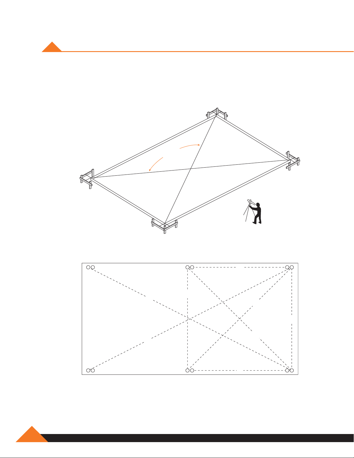
SQUARING OF FOUNDATION
For proper building erection, it is critical the foundation is square. The following examples are
suggested to ensure square foundation.
Dimensions
Must Be
Equal
Measurement:
A same as B
C same as D
E same as F
G same as H
Transit
G
A
B
F
C
E
D
H
A-2
877-2-MUELLER
Page 9
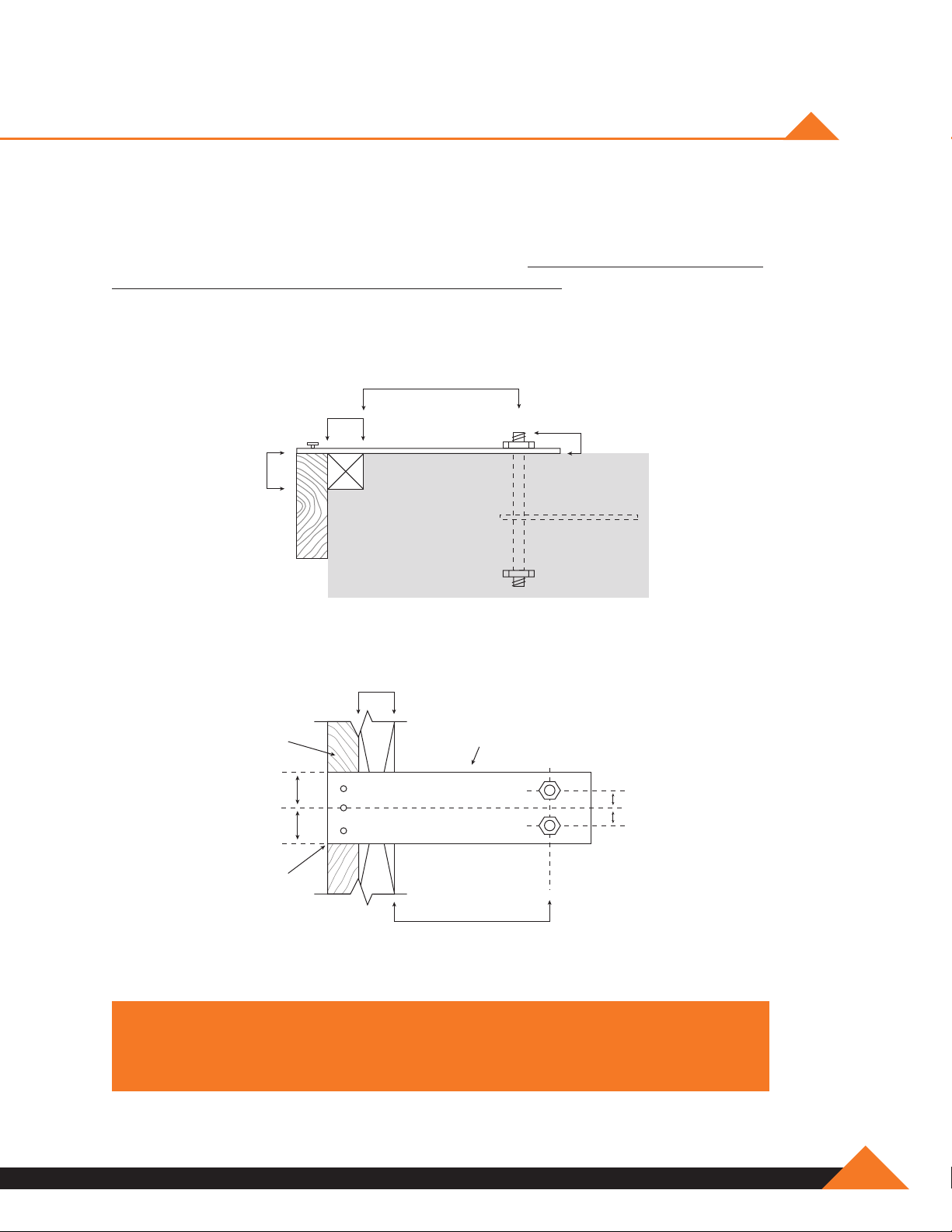
ANCHOR BOLT SETTINGS
It is extremely important that anchor bolts be placed accurately in accordance with the anchor bolt
setting plan. All anchor bolts should be held in place with a template or similar means, so they will
remain plumb and in the correct location during placing of the concrete. Check the concrete forms
and anchor bolt locations prior to the pouring of the concrete. A final check should be made after
the completion of the concrete work and prior to the steel erection. This will allow any necessary
corrections to be made before the costly erection labor and equipment arrives.
B
1
1
/2˝
D
1
1
/2˝
Projection of anchor bolts “D”
given on anchor bolt plan
1
/2˝
1
Form
Board
Template*
C
C
Steel
Line
B
Dimension of A, B and C as
given on anchor bolt plan
NOTE: Measurements are from steel line to steel line.
* Template not included.
A
A
www.muellerinc.com
A-3
Page 10
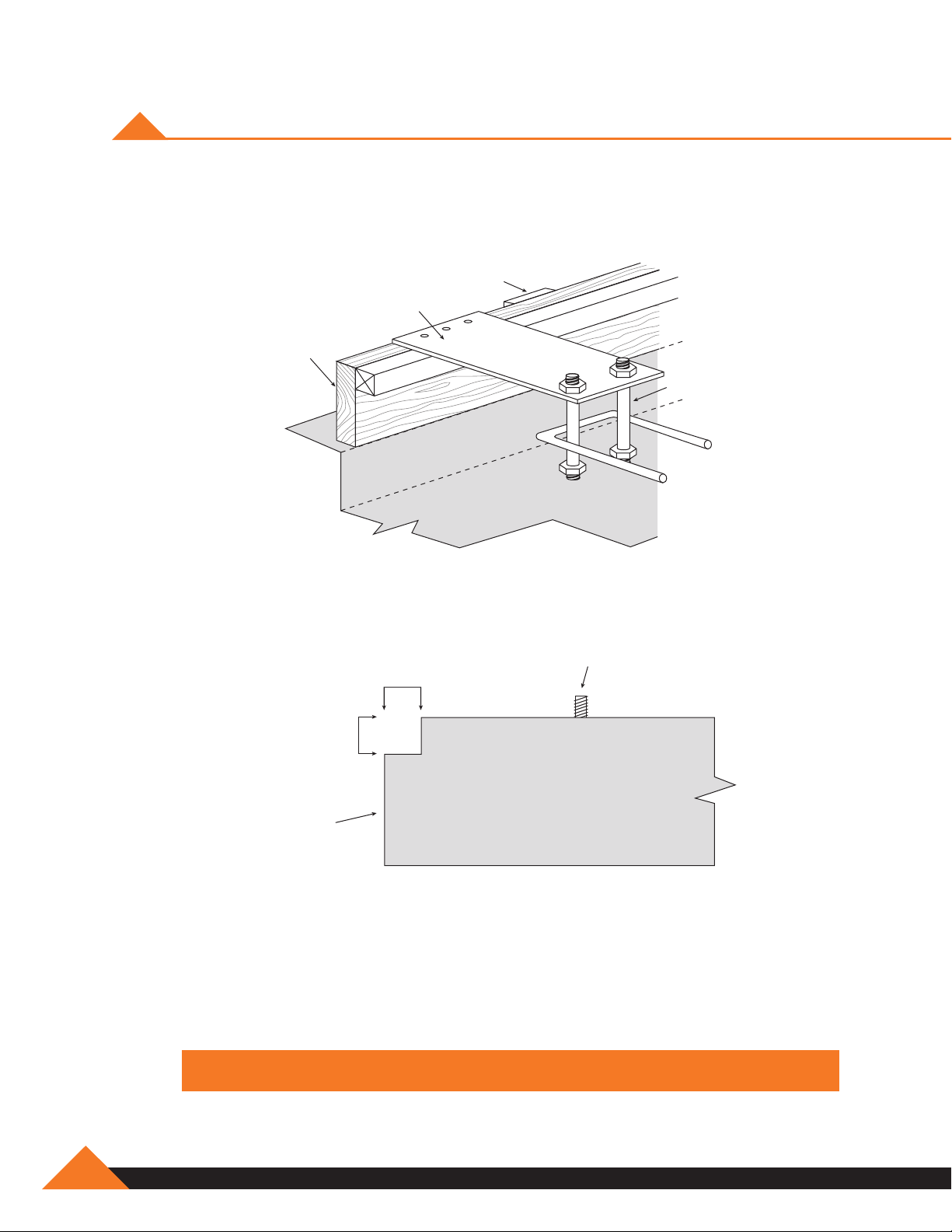
ANCHOR BOLT SETTINGS
Refer to your anchor bolt drawing for proper sizes and dimensions.
Stake
Template
Form
Board
Anchor
Bolts
1
/2˝
1
1
/2˝
1
Anchor Bolt
Foundation
Sheet
Ledge
NOTE: Suggested protrusion is 2 1/2" of threads above concrete.
A-4
877-2-MUELLER
Page 11

SECTION B
building delivery
and Storage
Page 12

Page 13

UNLOADING AND PREPARATION
OF PARTS FOR ASSEMBLY
The vehicle transporting your building parts must gain access to the building site from the
adjacent highway or road. Such access should be studied and prepared in advance of arrival.
All obstructions, overhead and otherwise, must be removed and the access route graveled or
planked if the soil will not sustain the heavy wheel loads.
A forklift or other type of power loader may be required to unload the truck and move the heavier
parts to the proper locations.
When the truck arrives with the building, unload the truck promptly, stack the steel parts evenly on
blocks and protect them from the weather.
Unloading and placing the steel parts of the building in the most convenient places for assembly
will make the process easier and faster.
NOTE: Prolonged exposure to the weather before assembly or stacking the steel
in a haphazard way can cause the painted parts to become damaged, or the
building parts to warp. Protect painted parts from moisture to prevent fading and
discoloring and stack the structural steel parts so they will be straight.
After unloading the truck and before the driver leaves, ensure that all parts have
been delivered.
1. Check each part against the delivery receipt. Each part is marked for identification.
2. Sign the delivery receipt if all parts are delivered.
3. If any of the parts are missing, notify the driver and note the missing items on the delivery
receipt before signing.
4. Check with your salesperson regarding the missing parts.
www.muellerinc.com
B-1
Page 14
UNLOADING, HANDLING, AND
STORAGE OF MATERIALS
Structure
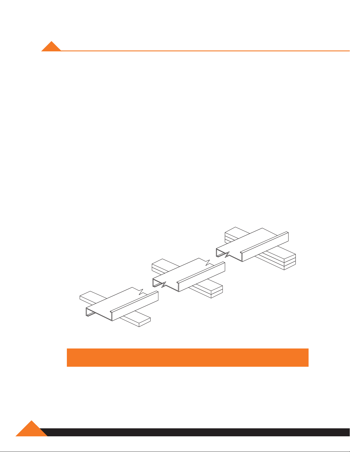
A great amount of time and trouble can be saved if the building parts are unloaded at the building
site according to a pre-arranged plan. Proper location and handling of components will eliminate
unnecessary handling.
Blocking under the columns and rafters protects the splice plates and the slab from damage
during the unloading process. It also facilitates the placing of slings or cables around the members
for later lifting and allows members to be bolted together into sub-assemblies while on the ground.
Extra care should always be exercised in the unloading operation to prevent injuries from handling
the steel and to prevent damage to materials and the concrete slab.
If water is allowed to remain for extended periods in bundles of primed parts such as girts,
purlins, etc., the pigment will fade and the paint will gradually soften reducing its bond to the steel.
Therefore, upon receipt of a job, all bundles of primed parts should be stored at an angle to allow
any trapped water to drain away and permit air circulation for drying. Puddles of water should not
be allowed to collect and remain on columns or rafters for the same reason.
All primer should be touched up as required before erection.
NOTE: Piece marks are stenciled on primary structural members.
B-2
877-2-MUELLER
Page 15
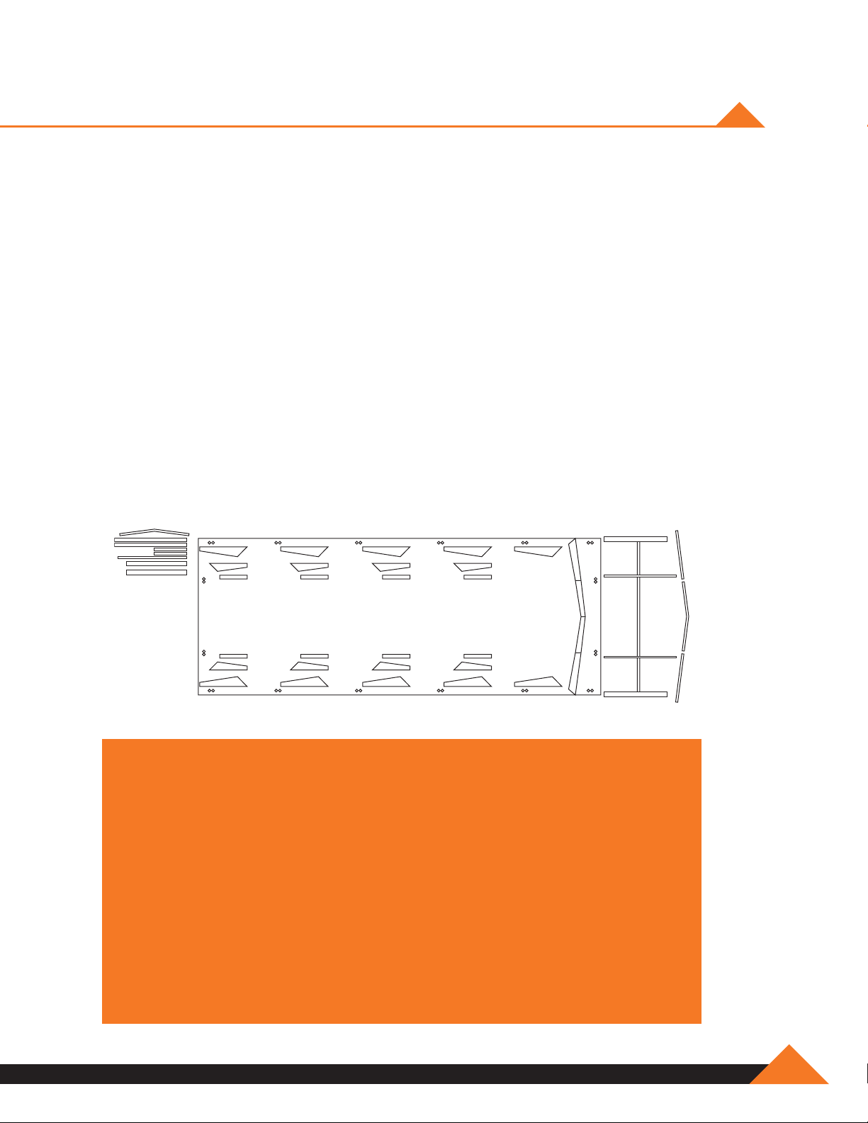
LOCATION OF BUILDING PARTS
Place the parts around the foundation so they will be in the most convenient locations for
installation. For example: place the end columns and rafters at the ends of the building and the
mainframe columns and rafters at the sides.
Place the bolts and nuts in a place where they will be accessible to the parts. You may want to
screw the bolts and nuts together and place them with the corresponding parts. This will save time
as you begin assembling the parts.
Purlins and girts, depending on the number of bundles, are usually stored near the sidewalls clear
of other packages or parts.
Sheet packages are usually located along one or both sidewalls off the ground and sloping to one
end to encourage drainage in case of rain.
Accessories are usually unloaded on a corner of the slab or off the slab near one end of the building
to keep them as much out of the way as possible from the active area during steel erection.
NOTE: When filing claims either with the carrier or Mueller, Inc.,
the claim should indicate the item(s) in question:
•Thebundleorcontainerinquestion(ifany)
•Theactualquantityreceived.
•Thequantitywhichshouldhavebeenreceivedorthat
which was damaged.
This is important for quickly retrieving the necessary information.
Also, the other information such as numbers, names and addresses should be
indicated on claims as well as invoice numbers.
These procedures are primarily for your protection, A shortage discovered
later can be caused by theft, misplacement or other causes
and neither the carrier or Mueller can accept responsibility.
www.muellerinc.com
B-3
Page 16

CARE AND HANDLING OF MUELLER SHEET METAL
Delivery
Mueller takes every precaution to ensure that material is delivered to the customer damage free
and fully protected from the elements during shipment. When the material is delivered to the
customer it then becomes the customer's responsibility to protect the material from the elements,
possible theft, and other damage. The following guidelines are recommended:
Handling: Proper care is required in unloading and handling panel bundles
in order to prevent damage.
1. Bundles should remain banded (if possible) during the unloading process. Bundles should
never be lifted by the banding material.
2. Lift each bundle as close as possible to its center of gravity.
3. If the bundles are to be lifted with a crane, use a spreader bar of appropriate length and
nylon band slings (do not use wire rope slings as they will damage the material).
4. Depending on the panel length, some bundles may be lifted by a forklift. When using a
forklift, the forks should be spread to their maximum spacing, and the load centered on the
forks. Sheets over 25’ long require two forklifts.
5. After panel bundles are opened, individual sheets must be handled carefully to prevent
panel buckling or damage to the panel coating. When removing a sheet from a bundle it
should be rolled off the bundle to prevent scratching of the next sheet. Never drag or slide
one sheet over another sheet. Sheets should not be picked up by the ends. Instead, lift the
sheet along its longitudinal edge and carry in a vertical position. For sheets over 10’ long,
two or more people may be required to carry the sheet.
B-4
877-2-MUELLER
Page 17

WALL AND ROOF PANELS
Mueller’s wall and roof panels including color coated, galvalume, and galvanized provide
excellent service under widely varied conditions. All unloading and erection personnel should fully
understand that these panels are quality merchandise which merit cautious care
in handling.
Under no circumstances should panels be handled roughly. Packages of sheets should
be lifted off the truck with extreme care taken to ensure that no damage occurs to ends of the
sheets or to side ribs. The packages should be stored off the ground sufficiently high to allow air
circulation underneath the packages. This avoids ground moisture and deters people from walking
on the packages. One end of the package should always be elevated to encourage drainage in
case of rain.
All stacked metal panels are subject, to some degree, to localized discoloration or stain when
water is trapped between their closely nested surfaces. Mueller, Inc. exercises extreme caution
during fabricating and shipping operations to ensure that all panel stock is kept dry. However, due
to climatic conditions, water formed by condensation of humid air can become trapped between
stacked sheets. Water can also be trapped between the stacked sheets when exposed to rain.
This discoloration caused by trapped moisture is often called wet storage stain.
The stain is usually superficial and has little effect on the appearance or service life of the panels as
long as it is not permitted to remain on the panels. However, moisture in contact with the surface
of the panels over an extended period can severely attack the finish and reduce the effective
service life. Therefore, it is imperative that all panels be inspected for moisture upon receipt
of the order. If moisture is present, dry the panels at once and store in a dry, warm place.
CAUTION: Care should always be taken when walking on panels. Use safety
lines and nets when necessary! Panels can be slippery due to paint finish,
wax, oil or atmospheric conditions. Always assume panel surface is
slippery and act accordingly.
www.muellerinc.com
B-5
Page 18

WALL AND ROOF PANELS (continued)
Storage:
It is recommended that sheets be stored under roof if at all possible. If sheets are to be stored
outside, the following precautions should be observed:
1. The storage area should be reasonably level, and located so as to minimize handling.
2. When stored on bare ground, place a plastic ground cover under the bundles to minimize
condensation on the sheets from ground moisture.
3. Store bundles at least 12 inches above ground level to allow air circulation beneath the
bundle, and to prevent damage from rising water.
4. Elevate one end of each bundle slightly to permit runoff of moisture from the top of the
bundle or from between sheets. A waterproof cover should be placed over the bundles to
allow for air circulation under the cover.
5. Inspect stored bundles daily and repair any tears or punctures in the waterproof cover.
6. Re-cover opened bundles at the end of each workday to prevent subsequent
moisture damage.
Drainage
Elevate
Air Circulation
Checking Order At Time Of Delivery
Check each order carefully, as it is unloaded. Report any obvious damage or shortages to the
carrier immediately. If damage or shortages are noted after delivery (at time of unpacking) notify
your Mueller representative immediately. Have invoice numbers and detailed descriptions of the
damage or shortage available. These procedures are for your protection. A shortage or damage
discovered later, can be caused by theft, misplacement, mishandling or other causes and is not
the responsibility of Mueller, Inc.
B-6
NEVER INSTALL MATERIAL IF THE QUALITY IS IN QUESTION!
877-2-MUELLER
Page 19

SECTION C
erection of PriMary
and Secondary
Structural
Page 20

Page 21

GENERAL INFORMATION
Many methods and procedures are in use for erecting the structural portion of metal buildings.
The techniques of raising frames vary from erecting small clear spans and endwall frames in units
to erecting the larger clear spans and modular frames in sections. The erection methods used
depend strictly on the type of building, the available equipment, the experience level of the crews,
and the individual job conditions.
The variations in these factors preclude the establishment of a firm or specific set of erection
rules and procedures. Consequently, the erection operation must be tailored by the erector to fit
individual conditions and requirements. However, there are certain erection practices, pertaining to
structural members, which are in general use and have proven sound over the years. Descriptions
of these follow.
Erectors are cautioned not to cut primary members (rigid frame columns, rafters, end bearing
frame rafters, interior columns). These are the primary support members for the frame and
are designed as such. Any cutting of these members may affect the structural stability. A
representative of Mueller’s must be consulted prior to attempting alterations of these members.
NOTE: Do not install any material if its quality is in question. Mueller, Inc.
will not be responsible for costs incurred associated with the installation
and/or removal of same.
WARNING! In no case should building erection be started on green concrete.
Anchor bolts may pull loose, concrete spall (chip out along edges) may occur
and equipment may crush or crack slab. Consult the project engineer, not
Mueller, Inc. on foundation questions.
www.muellerinc.com
C-1
Page 22

TOOLS AND EQUIPMENT REQUIRED
The types of tools and equipment required in order to assemble and erect the building depend on
the size of the building purchased. This part of the instruction manual lists the tools and equipment
that are normally required for most buildings. You may wish to use more or less power equipment
or different tools than are listed as the need dictates. Whatever tools are used, it is important
to remember that using the recommended tools will enable the least effort and best manner of
erecting the building.
If a contractor is going to erect the building for you, you will not have to concern yourself with the
tool list as most contractors have the necessary tools and equipment that are required. However,
reference to the following list may be of value to the contractor if he has never assembled and
erected a Mueller Prefabricated Steel Building.
WARNING! Whenver using any type of power equipment, it is important to follow
the manufacturer's recommendations for use. Always be aware of the dangers
involved when using electric or air powered equipment.
Tools
Spud Wrench
Hammer
Centering punch
Square
Complete set of Wrenches (Open-end,
socket, box-end)
Pry Bar
Pipe Wrench
Pliers
Vise-Grip Pliers
Drill Bits
Power Drill or Combination Power/Hammer Drill
Screw Gun
Power Wrench (Impact Wrench)
Nibbler (Electric metal cutter for cutting
across the wall & roof sheets)
Level (3 feet long minimum)
Hacksaw
Broom (Push)
Wire Brush
Caulking Gun (Open barrel)
Chalk Line (100’ long and chalk)
Channel Locks
Extension Cord (#10-3, 2/4 way box, 250’ long)
Fire Extinguisher (#10)
First Aid Kit
Load Binders
Plumb Bob
Snips (Large bulldogs)
Tape measure (12’ to 25’ long, 100’ long for
foundation measurements)
Ladder
Chain
Rope
Hoist or Forklift (Should be all-terrain)
Come-along (Power pull)
Saw Horses
Tarps
Safety Equipment:
Goggles
Hard Hat
Gloves,
Work Boots, etc.
C-2
NOTE: Additional tools may be required depending on
the specific requirements of the building.
877-2-MUELLER
Page 23
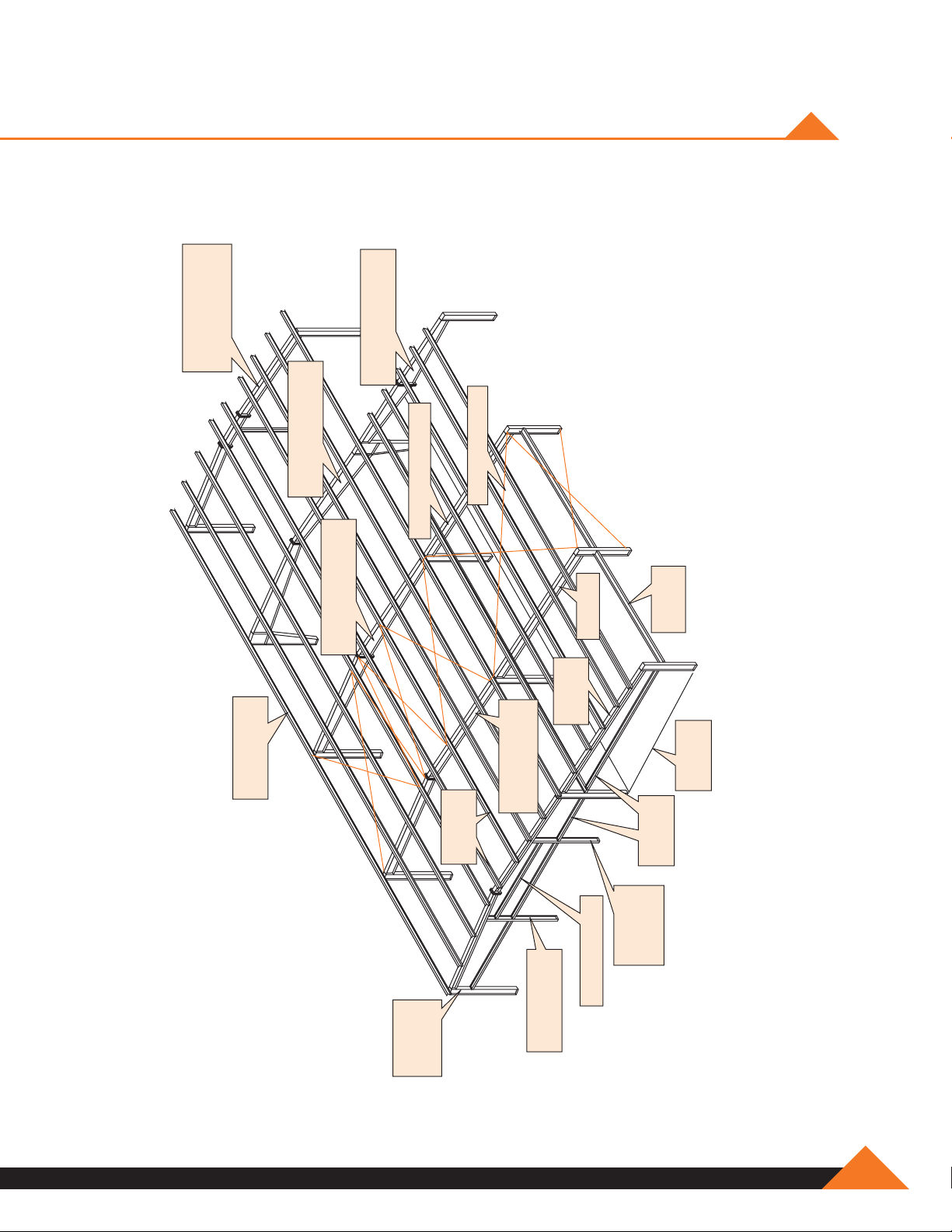
Rigid frame with
straight column &
pipe interior column
Rigid frame extension
with straight column
Rigid frame with
tapered column (MFR)
TYPICAL BUILDING PARTS
Cable bracing (BC)
Rigid frame extension
Eave strut /
Eave purlin (ES)
Rigid frame with
straight column (MFR)
Beam end
wall column
Long lap
(EWC)
Wide flange beam
Z-bar (LLZ)
Extension
End wall
extension
frame (MFR)
End wall interior
column (EWIC)
Z-bar wall
girt (WG)
End wall
girt (EWG)
End wall
door column
(EWDC)
Door header (DH)
Base
angle (BA)
www.muellerinc.com
C-3
Page 24
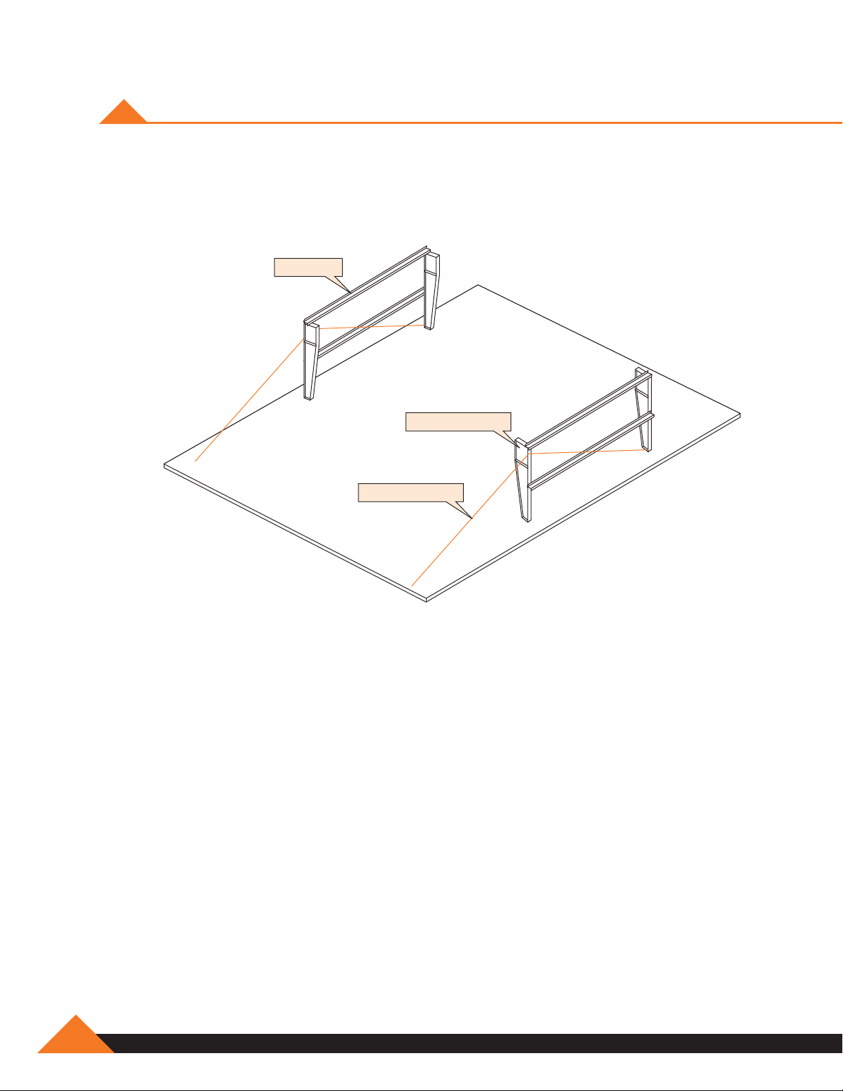
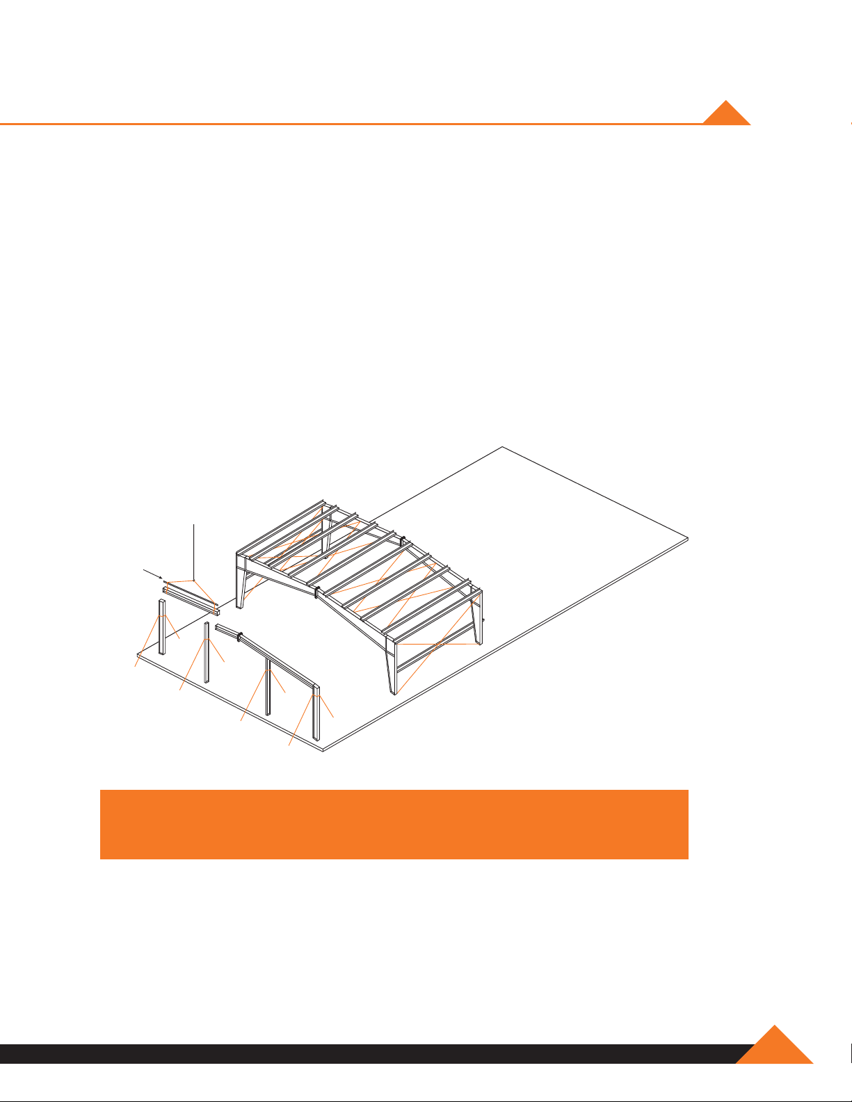
RAISING RIGID FRAMES
The intermediate or interior frames nearest the bearing endwall are usually erected first. This bay
usually contains the diagonal bracing. The proper completion and plumbing of this first bay is
extremely important to the successful completion of the building.
Braced bay
Stand columns first
Temporary bracing
Although several methods are used to erect rigid frames, it has been found most satisfactory to
erect the columns first, tie them together with the girts and tighten the anchor bolts*. On small
spans and short eave heights, columns can often be set in place by hand without the use of
hoisting equipment. Temporary bracing should always be installed as soon as sections are
lifted in place.
*The anchor bolt tension may need to be adjusted to seat the rafter.
C-4
877-2-MUELLER
Page 25
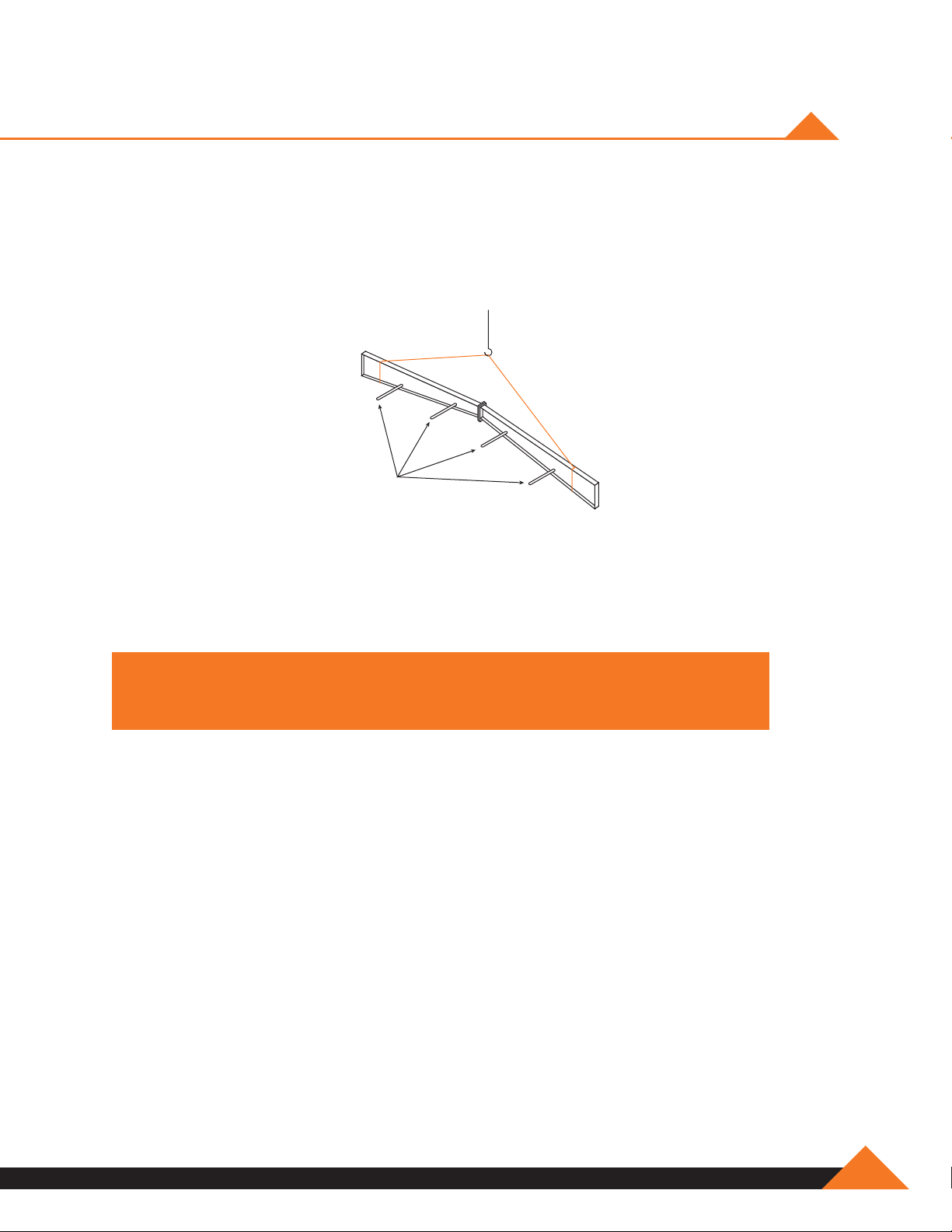
RAISING RIGID FRAMES (CONTINUED)
After the columns have been erected, the ground-assembled rafter is hoisted into place and
connected to the columns. The size of the rafter that can be safely handled depends on
the equipment available and the experience of the erection foreman. Generally as many
connections as possible are made on the ground.
Flange braces
loose bolted
The flange brace should be bolted to the rafter prior to raising in order to save time. The hoisting
equipment should never be released from the rafter until the frame is adequately braced,
so it cannot buckle or tip in the longitudinal direction of the building.
NOTE: Drawing above is intended as a general rigging method.
Actual rigging method will vary with member configuration.
www.muellerinc.com
C-5
Page 26
RAISING RIGID FRAMES (CONTINUED)
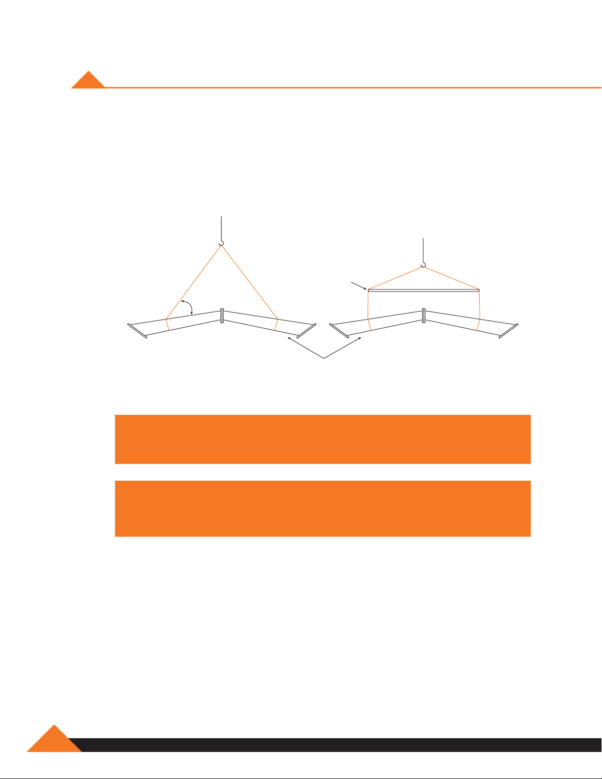
Lifting Cables And Spreader Bars
In all instances the length of the lifting cables should be such that the angle between the rafter and
the lifting cables is no less than 45 degrees. To reduce the severe compression stresses at the
ridge of the rafters that are created by the angle of lifting cables, a spreader bar is recommended,
which allows the lifting cables to be parallel to each other.
Spreader bar
45 degree
minimum
Rafters
NOTE: Drawing above is intended as a general rigging method.
Actual rigging method will vary with member configuration.
NOTE: Stay well in the clear of loads being moved by any lifting device.
Hands and feet should be kept clear of moving loads and never stand
under a load being lifted. Remember, SAFETY FIRST!
C-6
877-2-MUELLER
Page 27

RAISING RIGID FRAMES (CONTINUED)
Completing And Plumbing The First Bay
After the first intermediate or interior frames have been set, Mueller, Inc. recommends that all
purlins, girts, and eave struts be installed in the braced bay and the entire bay plumbed, aligned
and braced before proceeding further. If the building is designed without cable bracing, the erector
is responsible for providing temporary erection bracing.
When this bay is properly and accurately plumbed and braced, the remaining members, to a large
degree, will automatically plumb and align when installed. Only a final check of the building plumb
remains, and few adjustments, if any, will be necessary.
Interior Bay
NOTE: Purlin Nesting note goes here. Something about underclip
www.muellerinc.com
C-7
Page 28

RAISING RIGID FRAMES (CONTINUED)
When the rafters consist of several roof beams, as in the case of wide buildings, a safe procedure
of raising by sections and supporting the free end must be followed, regardless of the type of
equipment available. In most instances the work proceeds from outside columns inward toward
the peak until the entire frame is bolted into place.
The same general procedures of erection apply to either clear span or multiple span frames. In the
case of the latter, the support for rafter sections during erection is generally supplied by the interior
columns themselves, making temporary supports unnecessary.
Two words of caution concerning the erection of rigid frames are in order. The first is that rigid
frames, especially free ends or cantilevered sections should never be left “for the day” in an
unsupported, unbraced or unguyed condition. Such practice has resulted in the total loss of
considerable amounts of erected steel because of wind. The second word of caution pertains to
the additional care required in the erection of multiple span frames compared to clear span frames.
Frames with interior columns, because of closer supports, have much lighter sections. They are
much more apt to buckle during erection than clear span frames, and consequently require greater
care in rigging and handling.
Connection Bolts
Bolts used to make connections in secondary framing members such as the purlins are usually
1/2” diameter, ASTM designation A307. All primary framing or main framing connections are
made with ASTM A325 bolts, usually 5/8”, 3/4”, 7/8” and 1” diameters. The size and grade of the
bolt are marked on the building erection drawings.
MAIN FRAME: An assemblage of rafters and columns that support the secondary
framing members and transfer loads directly to the foundation.
SECONDARY FRAMING: Members that carry loads from the building
surface to the main framing. For example – purlins and girts.
C-8
877-2-MUELLER
Page 29
ERECTING COLUMN AND BEAM ENDWALLS
Column and beam endwalls of 50 feet or less in span may be raised into position and set on
the anchor bolts as a unit. All rafters, column, girts (except outside endwall girts which connect
to the sidewall girts), door headers, door jambs, clips, diagonal brace rods, etc. should be
assembled on the ground with the bolts left finger tight. A spreader bar should be used to raise
the endwall frame. Because of the flexibility of the column and beam frames, care must be taken
in locating the points of attachment of the cables, and in raising the frame, to avoid bending
about the minor axis.
For spans of 60 feet and greater, the columns are usually erected first and then capped with the
endwall rafter. The girts, headers, jambs and diagonal brace rods are then added between the
end columns. During this erection process, the frame must be properly braced or guyed before
the lifting lines are disengaged. Final bolt tightening should be done once the frame is plumb
and square.
Spreader bar
NOTE: Drawing above is intended as a general rigging method.
NOTE: Drawing above is intended as a general rigging method.
Actual rigging method will vary with member configuration.
Actual rigging method will vary with member configuration.
www.muellerinc.com
C-9
Page 30
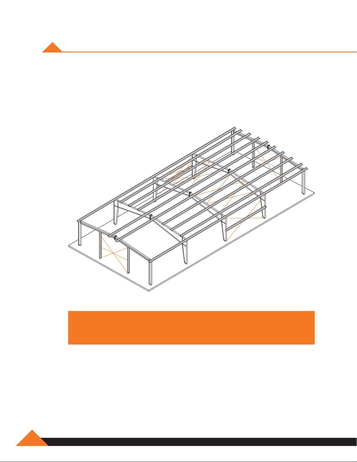
ERECTING THE REMAINING FRAMES & EAVE STRUTS
The remaining frames are erected in like manner, initially with only a few purlins being installed in
each bay working from one end of the building to the other. To lend overall rigidity to the structure,
install flange braces to the purlins at specified locations. All purlin, girt and eave strut connection
bolts are left loose so the entire skeleton framework can be plumbed without undue difficulty. The
remaining purlins can be positioned on the rafter in each bay to facilitate the completion of the roof
framing.
C-10
NOTE: Take precautions to secure structure during assembly. Temporary
bracing may be required to stabilize the structure during erection.
Never leave the structure unbraced.
877-2-MUELLER
Page 31

JOINTS NOT SUBJECT TO TENSION LOADS
Joints not subject to tension loads need only be tightened to the snug tight condition, defined as
the tightness attained by a few impacts of an impact wrench or the full effort of a man using an
ordinary spud wrench.
Joints Subject To Tension Loads
Two tightening procedures are specified for A325 bolts in joints subject to tension loads, turn-ofthe-nut method and direct tension indicator.
Turn-of-the-nut method – When turn-of-the-nut method is used to provide tension, first bring
enough bolts to a “snug tight” condition to ensure that the parts of the joints are brought into good
contact with each other. Next, place bolts in all remaining bolt holes and bring to “snug tight”.
Then additionally tighten all bolts – progressing from the bolts nearest the web, to the free edges.
During this operation there shall be no rotation of the part not turned by the wrench.
Tightening by use of a direct tension indicator – Tightening by this means is permitted provided
it can be demonstrated, by an accurate direct measurement procedure, that the bolts have been
tightened to specified tension.
Consult latest edition of the AISC Manual of Steel Construction for more complete instructions for
installing high strength bolts.
www.muellerinc.com
C-11
Page 32

ASSEMBLY OF BRACE CABLES
1. Assembly of brace cables:
NOTE: Cable may have to be field cut to proper length.
A. Insert grip through eyebolt.
B. Begin wrapping the grip around the cable, matching the crossover marks.
C. Continue until the lasts two wraps are left split the legs and apply separately.
D. Duplicate this procedure on each end.
Hillside
Washer
Brace Grip
Hex Nut
Flat Washer
Eyebolt or
Turnbuckle
Cable
Flat Washer
Hex Nut
Eyebolt or
Turnbuckle
Hillside Washer
Brace Grip
Beam Connection
Obtain the proper tension of the strand by tightening the nuts on the eyebolts.
2. Insert the “T” section on an angle through slot until round neck rests on web plate then turn
brace-eye 90 degrees.
3. Then pull brace-eye toward you until “T” section rests against back of web plate, square neck
locks brace-eye in place.
4. Attach the brace-grip to the brace-eye and then attach the brace grip to the cable.
C-12
877-2-MUELLER
Page 33

INSTALLATION OF WIND BRACING (CONTINUED)
Assemble the next brace cable the same way and connect to the next column to form an “X” with
the other cable.
Column
Cable
Turnbuckle
Eyebolt
To square the building, measure the length of the diagonals and tighten or loosen the turnbuckle/
eye-bolt until the lengths are the same. Double-check by using a square at the corners.
Brace each sidewall frame the same way so that you have an x-brace on each side. Note that the
diagonal lengths may vary between the two walls, but should be the same on each x-brace.
Tighten the column anchor nuts after ensuring that the building is square.
The diagonal bracing is cable. It should always be installed as shown on the erection drawing and
should be tensioned so that the building will not sway or rock when the wind blows. Care should
be taken; however, not to over tighten and bend the structural members. The workman should
watch the structural members carefully as he tightens the bracing.
www.muellerinc.com
C-13
Page 34

INSTALLATION OF THE WIND BRACING
Diagonal bracing in metal buildings is critical. They provide support for wind loads or other
longitudinal loads, such as those created by an overhead crane in the completed structure. Many
times additional temporary bracing is needed to stabilize the structure during erection. The erector
should review this requirement, and the erector should provide any additional bracing. On some
smaller buildings, diagonal bracing is not needed for the building design, so the erector must
furnish any erection bracing needed.
C-14
877-2-MUELLER
Page 35

INSTALLATION OF WIND BRACING (CONTINUED)
Hillside Washer Installation
Hex Nut
Flat Washer
Hillside Washer
NOTE: Hillside washer installation similar at base.
NOTE: Care should be taken not to over-tighten the wind bracing. Overtightening
the bracing can cause premanent damage to the framing.
www.muellerinc.com
C-15
Page 36

INSTALLATION OF WIND BRACING (CONTINUED)
Occasionally the bracing in the wall of a building cannot be installed in the specified bay because
of doors or other complications. Usually these can be moved to other bays without affecting the
structural integrity of the building. However, before moving any wind bracing check with
Mueller, Inc. Do not remove after building is erected.
Web of Column
Hillside Washer
Flat Washer
Eyebolt
Hex Nut
NOTE: Never modify a Mueller building without first contacting
a Mueller representative.
Cable
C-16
877-2-MUELLER
Page 37

inSulation
SECTION D
Page 38

Page 39

WALL INSULATION
Fiberglass blanket insulation is the most common type used, and these instructions pertain to this
type only. One side of the blanket insulation should have a vapor barrier that must face the inside
of the building regardless of whether the insulation is for heating or cooling.
Fiberglass insulation
to outside of building
Vapor barrier to
inside of building
Wall Insulation Installation
Cut the insulation to length allowing an additional 6” or more to facilitate handling. The wall panel
can be used as a guide.
NOTE: The insulation must compress between the girt and the wall dring
installation. Insulation too thick or dense to compress adequately will induce
waviness or oil canning in certain types of wall panels.
www.muellerinc.com
D-1
Page 40
WALL INSULATION (CONTINUED)
The first run of wall insulation should be installed so that its forward edge is just ahead of the
leading edge of the wall panel. This keeps the forward edge of the insulation ahead of the wall
panel for joining the next blanket.
Wood
Block
Clamping
Pliers
Wood
Blocking
Blanket
Insulation
Eave
Strut
Vapor Barrier
Attach base angle with
double sided tape
Cut Fiberglass
from Vapor
Barrier and
Wall Panel
NOTE: Do not allow the insulation to wick moisture from the floor.
WARNING! Insulation has no load bearing strength. Do not lean or prop material
against wall insulation. Observe all proper safety procedures when handling
fiberglass insulation, such as dust masks, gloves and long sleeved shirts, to
minimize contact with the insulation.
fold barrier up
D-2
877-2-MUELLER
Page 41

ROOF INSULATION
Pre-cut roof insulation to reach from eave to eave allowing approximately 2 feet of additional
length to facilitate handling. Hold insulation at one sidewall and roll out insulation across the
purlins, vapor barrier to the inside of the building. Stretch the insulation to provide a tight and
smooth inside surface.
NOTE: Insulation has no load bearing strength. Maintain body weight on
approved scaffold or walk boards.
www.muellerinc.com
D-3
Page 42

ROOF INSULATION (CONTINUED)
Double sided tape or contact adhesives can be used to hold insulation in place while the roof
sheets are being installed. Trim excess insulation to the edge of the eave trim and cut fiberglass
approximately 4 inches from end leaving only facing. Fold facing over end of blanket insulation to
seal the end.
Allow room to
install sealant tape
and closure strip
Cut Fiberglass from Vapor Barrier
and Fold Vapor Barrier Over
Eave Trim
(Trim shape
may vary)
#12 Self-Drilling
Wall Fastener
Outside Closure
(Optional)
NOTE: Do not install more insulation on the roof than can be covered by roof
panels before the work period ends. Do not allow the insulation to become wet.
Double-sided
Tape
Eave Strut
Blanket
Insulation
D-4
877-2-MUELLER
Page 43

ROOF INSULATION (CONTINUED)
Seal insulation sidelap joints by lapping 4” tab side. As on the walls, the general sequence is to
install the roof sheets in conjunction with the insulation.
First Roof
Panel
4' -0"
NOTE: The insulation sidelap must be lapped to prevent condensation and
minimize temperature loss at laps.
WARNING! Wipe oil and other slippery substances from roof panels. Do not step
on rib of panel, near a crease in the panel, near a side edge or within five feet of
the end of unsecured panel. Insulation has no load bearing strength. Maintain
body weight on scaffold or walk boards.
1' -0"
Double-sided Tape
Eave Trim
Blanket
Insulation
Eave Strut
www.muellerinc.com
D-5
Page 44

Page 45

Sheeting
SECTION E
Page 46

Page 47
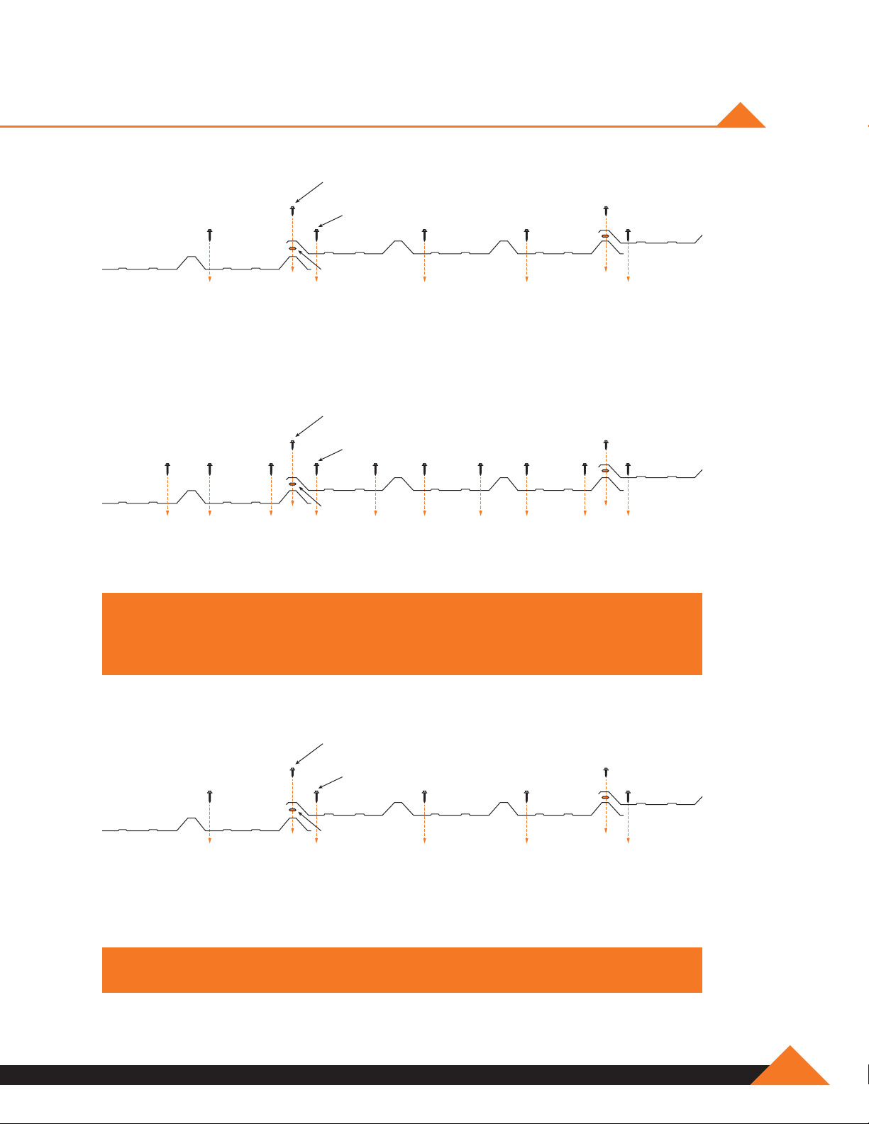
FASTENER LAYOUT
Lap Tek Screw
20" O.C. at sidelap
#12 Self Drill Roof Fastener
Sealant Tape
“R” and “PBR” Roof Panel Fastener Spacing,
Intermediate Purlins, Girts, Eave Strut
Lap Tek Screw
20" O.C. at sidelap
#12 Self Drill Roof Fastener
Sealant
Tape
“R” and “PBR” Roof Panel Fastener Spacing, Eave Strut, Wall and Roof
Panel End Laps, Ridge Purlin, Base Angle/Girt
NOTE: UL 90 Uplift Rated Roofs Require Fasteners At Each Side of High Ribs
At All Purlin On Certain “UL” Construction Systems And Eave Strut Locations
(Consult Your Specific Requirements Prior To Installation).
Lap Tek Screw
20" O.C. at sidelap
#12 Self Drill Roof Fastener
Sealant Tape
“R” and “PBR” Wall Panel Fastener Spacing,
Intermediate Girts, Eave Strut
WARNING! DO NOT OVERDRIVE FASTENERS!
www.muellerinc.com
E-1
Page 48

ALIGNING THE GIRTS
Installation of the building walls is generally done before the roof. Before starting the wall
installation, check to be sure that the eave strut and girts are straight and plumb. One method of
aligning the girts is to cut temporary wood blocking to the proper length and install between the
lines of girts. This blocking can be moved from bay to bay, which will reduce the number of pieces
required. Normally, one line of blocking per bay will be sufficient. Banding can also be used to hold
the girts straight and plumb.
Girt
Wood
Blocking
E-2
Typical construction of the wood blocking is show below. A 2" x 4" minimum board size should be
used. Refer to the cross section framing drawing that accompanied the building to determine the
girt spacing.
NOTE: Blocking should be secured to prevent falling hazzard.
877-2-MUELLER
Page 49

SCREW ALIGNMENT
Good alignment of the screws, especially on the wall panels, will give a professional appearance to
the wall panel installation. One way this can be accomplished is by pre-drilling holes in the panels
at identical locations. Up to 15 panels can be stacked together and drilled using a template panel.
Use 1/8” or 5/32” diameter drill bit for panel to structural fasteners and a 1/4” diameter bit for the
sidelap clearance holes. It is important to clean metal shavings off panel surfaces after
drilling to avoid rust stains.
Pre-Drilled
Template
Sheet
Stacked Sheets
To Be Drilled
CLAMPING IS REQUIRED
Keep Ends
of Panels
Allinged
www.muellerinc.com
E-3
Page 50

SCREW ALIGNMENT (CONTINUED)
The template panel should be laid out for the proper screw locations in accordance with the
building erection drawings. Since pre-drilling will “hand” the panels, it will also be necessary to
select the end of the building from which the paneling is to begin. Before drilling the template
panel, it should be checked for proper hole locations against the building framework. Be sure there
is no excessive deflection in the purlins and girts.
12˝ Lap
1˝
1
1˝ - 1
1
1
/2˝
3
/4˝
/2˝
Dimensions subject to
variations. Check building
erection drawings.
1
/4˝
1
2"
E-4
877-2-MUELLER
Page 51

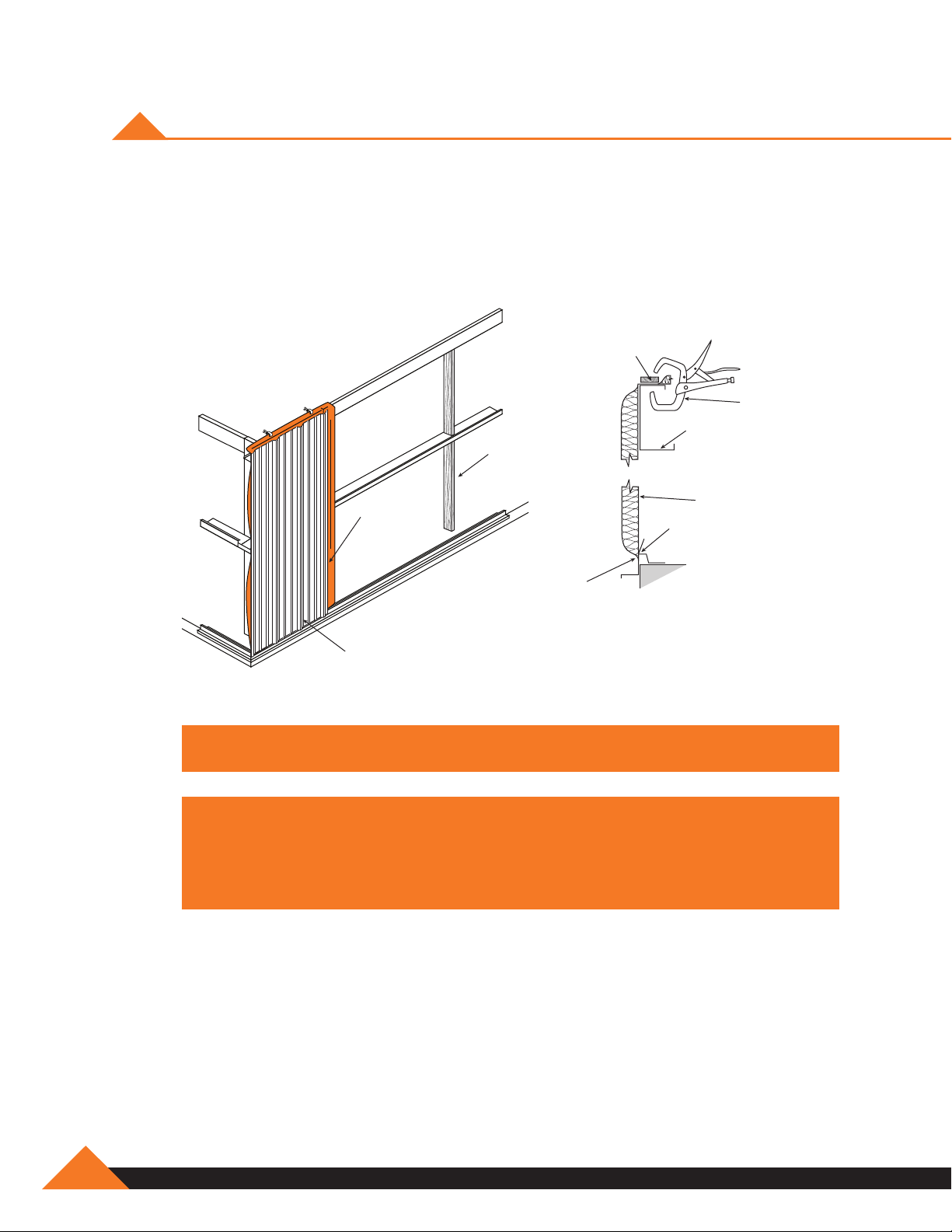
INSTALLATION OF WALL PANELS
Adjoining panels are installed with the overlapping rib toward the last erected panel. Position panel
to structural making sure that it is kept plumb and install fasteners at lapped rib. Check for proper
coverage (3' center to center) and correct as necessary. Install remaining fasteners.
Blanket
Insulation
Sheeting
Direction
Wood
Blocking
Steel Frame Line
Wall
Panel
NOTE: Start first panel with major rib centered with endwall frame.
Wall Panel
www.muellerinc.com
E-5
Page 52

INSTALLATION OF WALL PANELS (CONTINUED)
Backlapping the wall panels 1 foot or 2 foot is routinely done to match panel coverage with the
building width and length. On the sidewall this is done with the last panel installed. On the endwall
this is normally done near the center and will be marked on the erection drawings.
2'-0"
2'-0"
1'-0"
Sidewall
1'-0"
E-6
Endwall
877-2-MUELLER
Page 53

STANDARD SHEET LEDGE
Wall Sheet
(R-Panel Shown)
Base
Angle
Base Flashing
(Optional)
11/2" Sheet
Ledge
Spacing under
sheet
for edge creep
NOTE: Sheets must be at least two inches off the ground, or rust may occur.
OPTIONAL SHEET LEDGE WITH EXISTING SLAB
1
/8"
1
/8" to 1/4"
Wall Sheet
(R-Panel Shown)
Base
Angle
Base Flashing
NOTE: Sheets must be at least two inches off the ground, or rust may occur.
www.muellerinc.com
E-7
Page 54

FASTENER INSTALLATION
Correct fastener installation is one of the most critical steps when installing roof panels. Drive
the fastener in until it is tight and the washer is firmly seated. Do not overdrive fasteners: A slight
extrusion of neoprene around the washer is a good visual tightness check.
Always use the proper tool to install fasteners. A fastener driver (screw gun) with and RPM of
1700-2500 should be used for self-drilling screws. Discard worn sockets, these can cause the
fastener to wobble during installation.
Correct degree of
tightness. Note slight
circle of sealant
NOTE: Always remove metal shavings from surface of panels at the end of each
work period. Rusting shavings can destroy the paint finish and void any warranty.
Too tight! Sealant
squeezed too thin.
Extrudes far beyond
fastener head
Too loose!
Sealant is not
compressed to
form seal
Sealant Tape
Proper sealant tape application is critical to the weather tightness of a building. Sealant tape
should not be stretched when installed. Apply only to clean, dry surfaces. Keep only enough
sealant tape on the roof that can be installed in a day. During warm weather, store sealant tape
in a cool dry place. During cold weather (below 60 degrees) sealant tape must be kept warm (60
degrees – 90 degrees) until application. After sealant tape has been applied, keep protective paper
in place until panel is ready to be installed.
Panel Rib
Prevailing Wind Direction
Lap Tek Screw
(20" O.C.)
E-8
877-2-MUELLER
1
/4˝ Clearance Hole
Roof Panel
Sealant Tape
Roof Panel
Page 55

SAFETY NOTE! CAUTION!!! PANELS MAY BE SLICK
UNSECURED PANELS MAY SLIP IF STEPPED ON!
Never step on a single unsecured roof panel, or a stack of roof panels laying unattached on
the purlins.
Secure each end of the panel with clamps or appropriate fasteners and place walk boards of
adequate size and strength in the flat of any panels not fully secured to the purlins and supported
by panels on each side. Walk boards should run the full length of the panel and be fastened
together by drilling a hole near the end of each board and tied with rope to the next board. Cut a
groove in the bottom of each board so the board will lie flat and not tip back and forth because of
the rope.
NOTE: Always wear rubber sole work boots! When on the roof, use OSHA
approved protection devices such as safety lines, safety nets or catch platforms.
www.muellerinc.com
E-9
Page 56

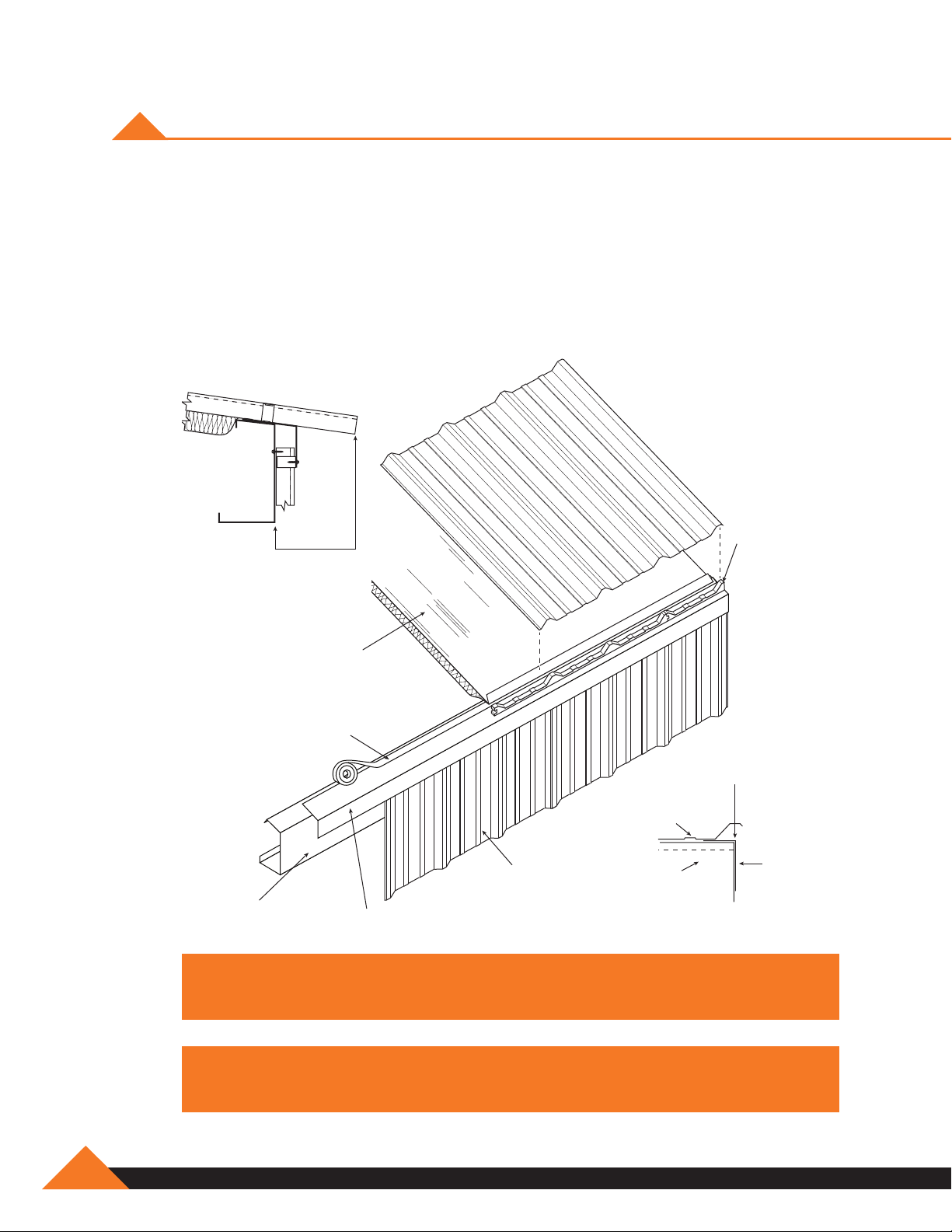
PREPARING THE EAVE
After installing the first run of insulation, prepare the eave for the first roof panel by applying
sealant tape along the eave outside of the insulation and leaving release paper in place. Sealant
must be applied in a straight line and without voids. Do not stretch the sealant. Use a knife to cut
if necessary. Cut an inside closure strip as shown and place starter piece on top of the sealant
(removing protective paper from the sealant only as required). Center the first major rib with edge
of the endwall frame. Splice a full closure to the starting closure and apply along the top of the
eave sealant. If roof is subject to ice and snow build-up, the splice in the closure strip must be
caulked to ensure weathertightness.
Starter
Panel
Edge
1'- 0"
4'- 0"
One Half
Inside Closure
Blanket
Insulation
Double-sided Tape
Eave
Strut
NOTE: Insulation has no laod bearing strength. Maintain body weight on
1'- 0"
Eave Flashing
approved scaffolding or walk boards.
Cut
Full Inside Closure
Wall Panel
Align with Roof Line
Cut Closure Here
E-10
877-2-MUELLER
Page 57

PREPARING THE EAVE (CONTINUED)
Along the top of the closures that have been placed along the eave, apply a second run of sealant
tape. Prior to removing paper backing, check and mark for proper alignment of the first roof panel.
Continue sealant tape and closure run along eave in preparation for the next roof panel.
Insulation
Eave Strut
(Shape
may vary)
Insulation
Cut & Fold
Insulation
Double-sided
Tape
Wall Fastener
Sealant Tape
Sealant Tape
Inside Closure
Sealant Tape
Eave Trim
(Trim shape
may vary)
Wall
Fastener
Outside Closure
(Optional)
Wall Panel
Caulk closure splice
when ice & snow eave
conditions may occur.
Sealant Tape
www.muellerinc.com
E-11
Page 58
INSTALLATION OF FIRST ROOF PANEL
Once the eave is prepared, the first roof panel may be installed. Check the erection drawings to
determine the roof overhang at the eave. Set the roof panel in place over the inside closure (after
removing the paper from the sealant tape) ensuring the major ribs of the panel nest properly
with the inside closure. Align the center of the major rib of the panel edge with the edge of the
endwall roofline. With the panel properly placed, secure the panel to the structure with appropriate
fasteners. If the building requires more than one panel per run, do not install fasteners at the purlin
located at the upslope end of the panel. These fasteners will be installed after the overlapped
panel is installed.
Inside
As required
on erection
drawings
Closure
Blanket
Insulation
Double-sided Tape
Panel
Wall Panel
Eave
Strut
NOTE: For a professional finish, roof panel ribs should be in line with
WARNING! Do not walk on unsecured panels. Wipe oil and other slippery
Eave Flashing
wall panel ribs.
substances from roof panels. SAFETY FIRST!
Purlin
Panel Rib
Endwall
Roof Line
E-12
877-2-MUELLER
Page 59

INSTALLATION OF ROOF PANELS
With the first panel run installed and secured, and sidelap sealant applied, the second panel run
may be started. Prepare the eave with an inside closure and sealant tape as shown previously.
Position the panel so the overlapping ribs will nest properly. Be sure to check for proper overhang
and panel coverage. Lap screw the major ribs of the two panels together, and fasten panel to
the purlins.
Blanket
Insulation
Double-sided Tape
Sealant
Tape
Inside
Closure
Wall Panel
Eave
Strut
NOTE: If peak sheets are being used at the ridge, it is critical that the ribs on the
Eave Flashing
roof panels from both sides align.
WARNING! Sweep up all drill shavings from panels at the end of each work
period to minimize surface rust and damage to panel finish.
www.muellerinc.com
E-13
Page 60

“R” PANEL
High Side Attachment
(6 Fasteners Per Panel)
Slope
R Panel
Sidelap Attachment
(See Detail B)
Eave Attachment
(6 Fasteners Per Panel)
Self Drill
(6 each
per panel)
Sealant Tape
Intermediate Purlin
Attachment
(3 Fasteners Per Panel)
12"
R Panel
Sealant Tape
Detail A Detail B
Sealant Tape
Endlap Attachment
(See Detail A)
Lap Tek Screw
(20" O.C.)
Sidelap
1. Sealant tape must be installed between weather infiltration point and fastener.
2. Install Lap Tek fasteners at 20” on center.
E-14
3. When possible, install panels such that sidelaps are nested away from prevailing winds.
Endlap
1. Double bead sealant tape must be installed between weather infiltration point and fastener.
2. Install self-drilling fasteners on each side of major ribs of panel (two fasteners per foot).
877-2-MUELLER
Page 61

ROOF SHEETING SEQUENCE
It is recommended that both sides of the ridge of a building be sheeted simultaneously. This will
keep the insulation covered for the maximum amount of time and the panel ribs can be kept in
proper alignment for the ridge panel. Check for proper coverage as the sheeting progresses. Note
panel-sheeting sequence below.
11
10
12
8
7
4
2
1
NOTE: If slippery substances are present on the roof panels wipe them clean
immediately to prevent slipping or falling. Workers should maintain a constant
awareness of their location relative to the roof edge.
9
5
6
3
www.muellerinc.com
E-15
Page 62

SECTION AT EAVE
Insulation
Panel
Double-sided
Tape
Roof Fastener
Sealant Tape
Closure
Sealant Tape
Eave Trim
(Trim shape
may vary)
Wall Fastener
Eave Strut
NOTE: Check erection drawings for appropriate overhang dimensions.
Lap Screw
Wall Panel
E-16
877-2-MUELLER
Page 63

SEALING THE SIDELAP
Apply the sidelap sealant tape to the weather side edge of the lower panel’s major rib as shown.
The sealant tape should only be applied to clean, dry surfaces. With the release paper in place,
press firmly along the length of the sealant to ensure proper adhesion. In removing the protective
paper from the sealant tape, care should be taken not to pull the sealant tape away from the
panel. Install the adjoining panel positioning the overlapping rib with care.
Panel Rib
Lap Tek Screw
(20" O.C.)
Prevailing Wind Direction
1
/4˝ Clearance Hole
Roof Panel
Sealant Tape
Roof Panel
NOTE: Sweep up all drill shavings from panels at the end of each work period to
minimize surface rust and damage to panel finish.
www.muellerinc.com
E-17
Page 64

SEALING THE EAVE
Sealant tape location at the eave is critical. To ensure a weather tight seal, the sidelap sealant
must extend down from the top of the rib to the sealant on the eave closure. The sealant extension
must splice into the eave sealant tape.
Sealant
Tape
Sealant Tape
(Above & Below
Closure)
Sealant Extension
Inside Closure Strip
with Adhesive Backing
NOTE: Workers should maintain a constant awareness of their location in relation
to the roof edge at all times.
Fastener
Panel
Major Rib
E-18
877-2-MUELLER
Page 65

SEALING THE ENDLAPS
At the panel endlaps place a run of sealant tape across the full panel width ½" below the fastener
line. The panel endlaps have a 12" minimum overlap located over a purlin as shown. Locate the
fasteners 1” above the purlin web according to the fastener layout.
12" Lap
Ridge
Roof Panel
Sealant
Tape
NOTE: Do not step on panel endlaps until fully secure with fasteners.
Roof Fastener
Purlin Web
Sealant
Tape
Purlin
Eave
www.muellerinc.com
E-19
Page 66

PANEL ENDLAPS
Apply sealant tape to far side of major rib to complete seal at panel lap.
Roof
Fasteners
Sealant
Tape
12" Lap
1
/2"
Down Hill
E-20
877-2-MUELLER
Page 67
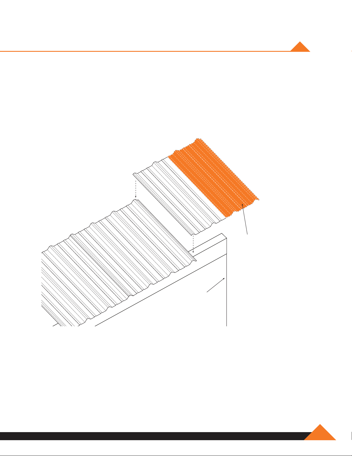
INSTALLATION OF FINAL PANEL
While backlapping the last roof panel (to match panel coverage with the building length) is routinely
done, this installation method can compromise the integrity of the roof by trapping moisture
between the panels. This moisture could, in time, create an environment conducive to rust and
metal failure. Manufacturer recommends field cutting the final panel lengthwise to create
the desired panel width necessary to finish off the building. The cut edge of the panel
should always be installed on the outside edge, not the lap edge. The “narrow” panel should be
handled with care, and foot traffic avoided until the final panel is completely installed.
End of
Building
Place Cut Edge To
Outside of Building
www.muellerinc.com
E-21
Page 68

ROPE SEALER PLACEMENT
Panel Rib
Prevailing Wind Direction
1
/4˝ Clearance Hole
Roof Panel
Inside & Outside Closure Placement
Lap Tek Screw
(20" O.C.)
Sealant Tape
Roof Panel
Outside Closure Strip
Sealant Tape
Steel Roofing
or Siding
Inside Closure Strip
Sealant Tape
E-22
877-2-MUELLER
Page 69

DIE FORMED TRANSITION TRIM
12"
Transition Trim
1
/2"
1
Sealant Tape
3
1"
1
/2"
10'-0"
31/4"
3
/4"
3
1
/4"
3
/8"
6"
1
1
/2"
2"
1
/2"
2
Multiple Uses
Wall
Roof Sheet
Transition Trim
Roof Sheet
Transition Trim
Roof Sheet
Wall Sheet
Transition Trim
Roof Sheet
www.muellerinc.com
E-23
Page 70

SAFETY PRECAUTIONS FOR ROOFING WORK
Manufacturer strongly recommends that erection employees be continuously trained in safe and
productive work practices. Working on the roof area in the installation of roof structurals, insulation
or roof panels requires proper training, correct equipment and constant alertness to minimize the
danger of falls. Hard hats should be worn on job sites to prevent injury from falling objects. Safe
work practices on all erection duties should be carefully reviewed with erection crews prior to
beginning each job.
NEVER STEP ON SKYLIGHTS OR TRANSLUCENT PANELS!
WARNING! Panels May Collapse If Not Properly Secured.
Roof panels must be completely attached to the purlins and to panels on either side before they
can be a safe walking surface. Skylights or translucent panels can never be considered as a
walking surface.
PARTIALLY ATTACHED OR UNATTACHED PANELS
SHOULD NEVER BE WALKED ON!
DO NOT:
1. Step on rib at edge of panel.
2. Step near crease in rib at edge of panel.
3. Step within 5 feet of edge on unsecured panel.
A single roof panel must never be used as a work platform.
E-24
877-2-MUELLER
Page 71

UL 90 LIGHT TRANSMITTING PANEL INSTALLATION
R-Panel
Sealant Tape
Slope
R-Panel
Sealant Tape
Slope
Install roof panels, leaving the light-transmitting panel run open, except for lower light transmitting
panel run panel. Install sealant tape to panel sidelaps and across panel width as normal.
Lay light transmitting panel in place overlapping lower metal panel 12”. Do not install any fasteners
at this time. Install sealant tape down light transmitting panel side laps. Apply double run of sealant
tape across light transmitting panel width at lower and middle purlins. Sealant tape should align
with beginning and ending edge of top flange of purlin. At the upslope end of light transmitting
panel, apply double run of sealant tape for endlap.
Install 3” long pieces of “R” panel over light transmitting panel at the lower and middle purlins.
Attach to purlins with six fasteners per piece of “R” panel. Fasteners must go between the two
runs of sealant tape that were installed previously.
www.muellerinc.com
E-25
Page 72

UL 90 LIGHT TRANSMITTING PANEL
INSTALLATION (CONTINUED)
R-Panel
Sealant Tape
Slope
Lap 12" O.C.
Slope
Apply sealant tape across sidelaps of 3” long pieces of “R” panel. Be sure the light transmitting
panel sidelaps have a complete run of sealant tape on top of the light-transmitting panel.
Install “R” panel hat section to each side of light transmitting panel with lap screws at 12” O.C.
Apply sealant tape down each hat section to just downslope of exposed sealant tape running
across light transmitting panel. Also apply additional sealant tape up each side of hat section
aligning and sealing to the exposed sealant tape running across light transmitting panel.
E-26
Install upper metal panel in light transmitting panel run and fasten as at a normal endlap.
877-2-MUELLER
Page 73

triM
SECTION F
Page 74

Page 75

FLASHING, GUTTER AND TRIM
The correct installation of flashing, gutters, and trim cannot be overemphasized. The overall
appearance of the finished building depends primarily on the quality of the installation of the
flashing, gutters and trim. Keep all gutter and flashing lines straight. Make all bends sharp and
neat. Be sure edges are not jagged, dented, crimped, or serrated. End joints and laps must be
closely controlled.
Eave Trim
Gutter
Ridge Roll
Flashing
Rake
Trim
Peak Sheet
Ridge
Rake
Angle
Peak Box
Wall Panel
NOTE: Flashing should be stored off the ground to avoid moisture and handling
damage. Elevate one end of the package above the lower end to encourage
drainage in case of rain. Always wear gloves when handling sheet metal.
WARNING! Mueller trim comes with a protective film coating to aid in the
prevention of scuffing. Do not allow this film to be exposed to te sun. Exposure
will bond the film to the metal making removal difficult.
www.muellerinc.com
F-1
Page 76

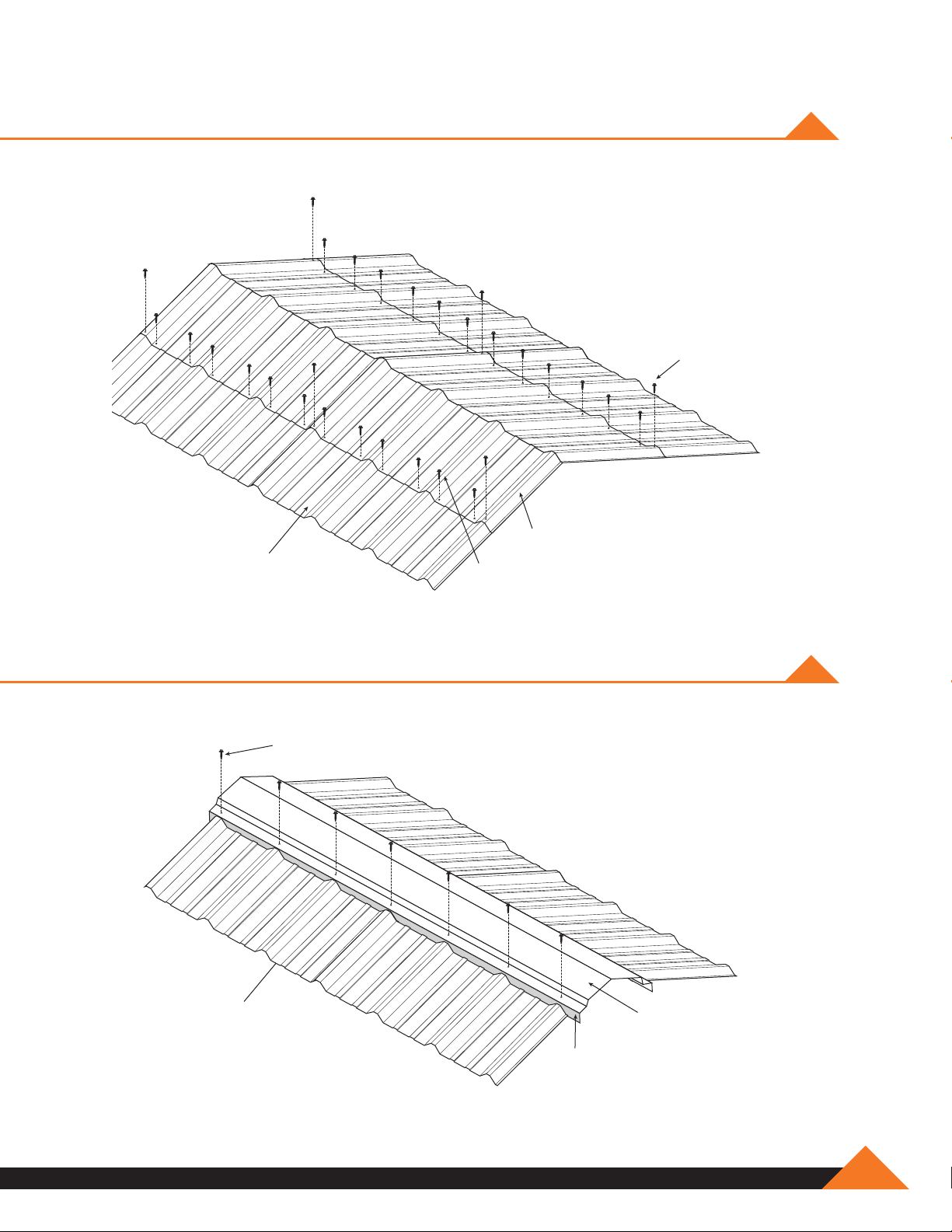
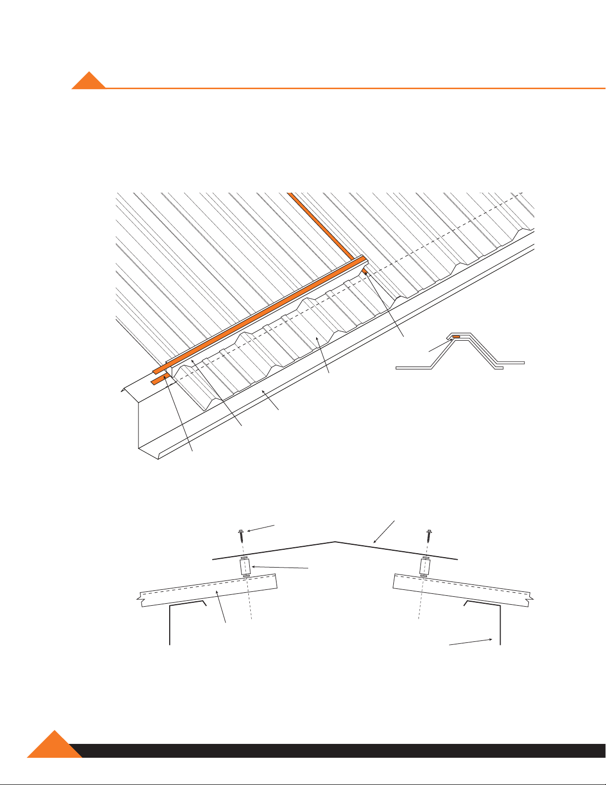
PEAK SHEET RIDGE INSTALLATION
Peak sheet ridge panels are to be installed as each side of the roof is sheeted. This will aid in
keeping both sides of the roof aligned. After having installed a run of panels on each side of the
roof, apply sealant to the panels as shown. Set die formed ridge panel in place and install lap and
purlin fasteners. Apply sealant tape along the top of the leading rib to prepare for the next sidelap.
Roof
Fasteners
Die Formed
Ridge
F-2
877-2-MUELLER
Sealant
Tape
Ridge
Purlins
NOTE: Do not walk on unsecured ends of panels.
See Building
Erection
Drawings for
Dimension
Page 77
TYPICAL SCREW PLACEMENT ON PEAK SHEETS
Lap Tek Screw
Peak Sheet
Roof Sheet
(R-Panel Shown)
Self Drill Screw
TYPICAL SCREW PLACEMENT ON RIDGE ROLL
Lap Tek Screw
(1' Typical)
Roof Sheet
(R-Panel Shown)
Outside
Closure
Ridge Roll
www.muellerinc.com
F-3
Page 78
SEALANT TAPE APPLICATION AT RIDGE FLASHING
Apply panel sidelap sealant tape as shown for building with ridge flashing and outside closures.
The sealant tape is placed along the inside edge of the major rib from the ridge purlin web line to
the upper end of the panel.
Ridge Flashing Detail
Sealant
Tape
Sealant
Tape
Outside
Closure
Roof
Panel
Roof
Panel
Peak
Purlin
Ridge Flashing
Fastener
Outside
Closure
Purlin
F-4
877-2-MUELLER
Page 79

RAKE TRIM AND PEAK BOX INSTALLATION
Rake trim and/or peak box should lap over rake trim a minimum of 2 inches. Attach to wall panel
with lap tek screws. Peak box may be attached to rake trim with lap tek screws or rivets. Seal the
connection at the roof panel with sealant tape or caulk.
Rake
Trim
Roof Panel
Peak Box
Sealant
Tape
Wall Panel
NOTE: Mueller recommends an outside closure under bottom edge of rake trim,
to prevent birds from nesting in trim. this works well with buildings with less
than 2:12 slope.
NOTE: If last rib is removed, cut 1" beyond the wall sheet line, then fold edge up.
www.muellerinc.com
F-5
Page 80

CORNER TRIM
Outside Corner Detail
R-Panel Outside
Corner Trim
Lap Tek
24" O.C.
Wall Girt
Inside Corner Detail
(Used with liner panel condition only)
R-Panel
Wall
Girt
Inside
Corner Trim
Lap Tek
24" O.C.
F-6
NOTE: Install corner trim with lap tek faseners 24" O.C.
877-2-MUELLER
Page 81

STANDARD EAVE TRIM
Tek Screw in
Flat of Sheet
Roof Panel
Tek Screw
Purlin or
Eave Strut
Sealant Tape
Inside Closure
Sealant Tape
Standard
Eave Trim
Lap Tek Screw
Wall Panel
Standard Eave / Sculptured Rake Trim With Rake End Cap
Rake Trim
Rake End
Standard
Eave Trim
Corner Trim
NOTE: Roof sheet should extend 2" to 3" past eave trim.
Cap
www.muellerinc.com
F-7
Page 82

SCULPTURED EAVE TRIM
Tek Screw in
Flat of Sheet
Roof Panel
Tek Screw
Purlin or
Eave Strut
Sealant Tape
Inside Closure
Sealant Tape
Sculptured
Eave Trim
Lap Tek Screw
Optional Closure
Wall Panel
F-8
877-2-MUELLER
Page 83

SCULPTURED EAVE / RAKE TRIM
WITH CORNER BOX
Rake Trim
Sculptured
Eave Trim
NOTE: Roof sheet should extend 2" to 3" past eave trim.
Pop Rivets or
Lap Tek Screws
Corner Box
www.muellerinc.com
F-9
Page 84

MUELLER GUTTER SYSTEM DIAGRAM
Gutter Strap
Roof Panel
Purlin or
Eave Strut
Pop Rivet or
Lap Tek Screw
Wall Panel
Gutter
Downspout
Sleeve
Wall Girt
Pop Rivet or
Lap Tek Screw
Base Angle
Downspout
Strap
Downspout
Downspout
Kickout
Base Trim
F-10
877-2-MUELLER
Page 85

Gutter Strap
Roof Panel
Purlin or
Eave Strut
Screw Placement Side View
GUTTER STRAP INSTALLATION
Lap Tek Screw in
Flat Area of Sheet
Gutter
Gutter Strap
Screw Placement Top View
Gutter
Metal
Roofing
Lap Tek
Screws
www.muellerinc.com
F-11
Page 86

DOWNSPOUT SLEEVE INSTALLATION
Pop Rivets
Inside Bottom
of Gutter
Gutter
Downspout
Sleeve
Gutter
F-12
Downspout
Sleeve
877-2-MUELLER
Page 87

GUTTER WITH CORNER BOX
Rake Trim
Gutter
Gutter Strap
Pop Rivets or
Lap Tek Screws
Corner Box
www.muellerinc.com
F-13
Page 88

DOOR TRIM INSTALLATION
“J” trim pieces are provided to trim out edges around framed openings. “J” trim pieces should be
attached to door columns and header before wall sheets are attached. After trim is attached, the
trimmed wall sheets can be inserted behind the “J” trim then screwed down in place.
Door Head
Trim
Door Jamb
Trim
F-14
Door Opening
NOTE: Clean all metal shavings from wall sheets to ensure against damage to
the coating.
877-2-MUELLER
Page 89

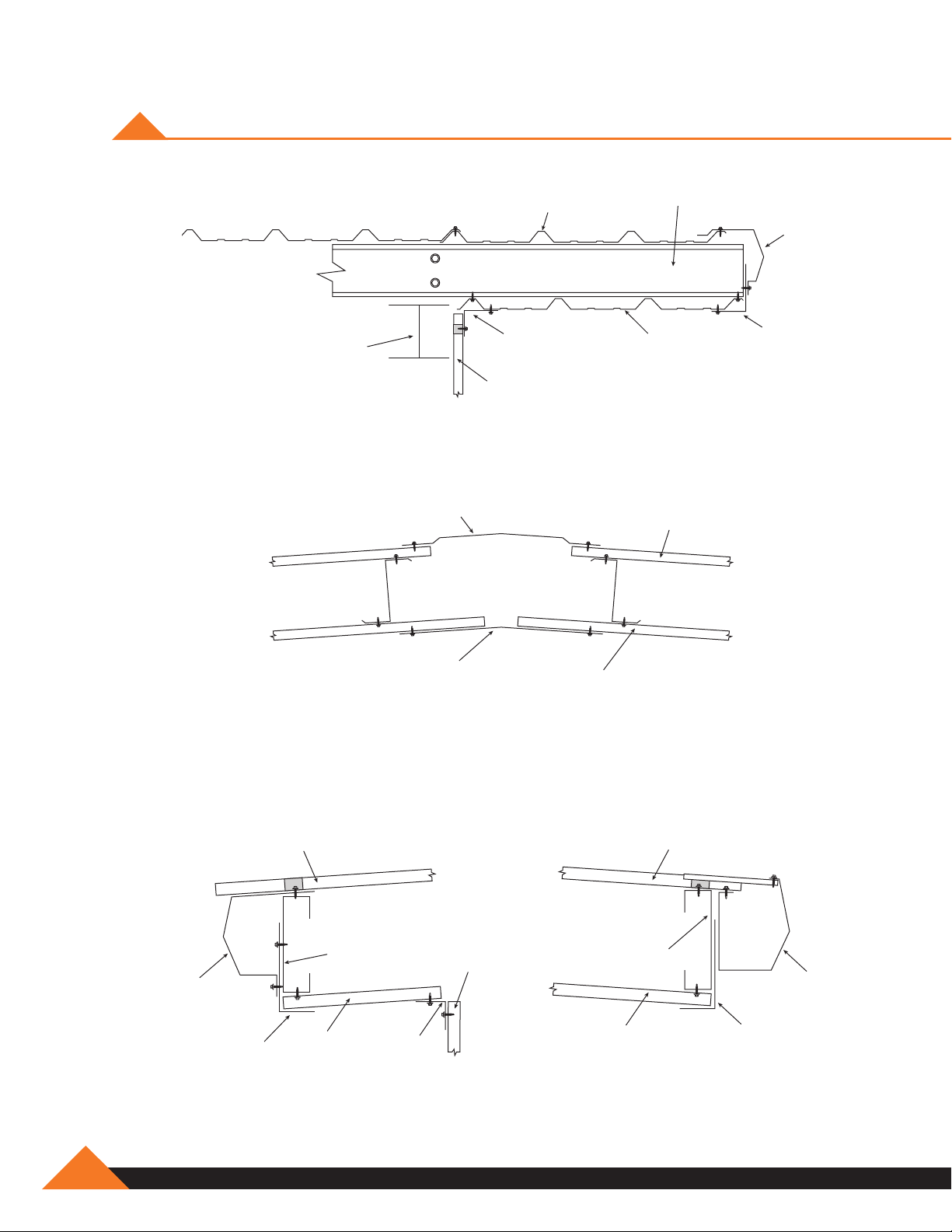
TYPICAL DETAILS – HEAD/JAMB
Jamb
Wall Girt
Self-Drill Screw
R-Panel
Head
3' O.C.
Door Jamb
Jamb Trim
R or U-Panel
Self-Drill
Screw
NOTE: Install jamb and head trim with self-drilling fasteners at 3' O.C.
Purlin
Self-Drill
Screw
Door HeadHead Trim
www.muellerinc.com
F-15
Page 90
OVERHANG TRIM DETAILS
Purlin
Endwall Overhang
Roof Panel
Rake
Trim
Endwall
Rafter
Endwall Overhang At Ridge
Ridge Roll
Flashing
Angle
Flashing
Wall Panel
Soffit
Sheet
Soffit Sheet
Angle
Flashing
Roof Panel
F-16
Sidewall Overhang With Eave Trim Sidewall Overhang With Gutter
Roof Panel
Purlin
Soffit
Sheet
Eave
Trim
Angle
Flashing
877-2-MUELLER
Roof Panel
Soffit
Sheet
Purlin
Wall
Panel
Angle
Flashing
Gutter
Angle
Flashing
Page 91

doorS and
acceSSorieS
SECTION G
Page 92

Page 93

PERSONNEL DOORS
Personnel (walk-in) doors can be installed at any location in the building. Wall girts below the
standard level of seven feet four inches will have to be cut out for the doorframe.
After deciding where the door is to be located and before the wall sheets are installed, attach the
doorframe to the foundation and the wall girt or girts. The doorframe can be bolted to the girt and
foundation where and however desired. The base angle will have to be cut out in the door opening.
Purlin
Wall Girt
at 7'4"
Bolt frames
to girt on
both sides
Bolt frames
to foundation
on both sides
Threshold
Make sure the doorframe is square so the door will fit and open and close properly.
After the doorframe is installed and squared, the door can be placed on the hinges, the doorknob
and locks installed, and the threshold plate placed at the bottom of the door opening.
Base Angle
www.muellerinc.com
G-1
Page 94
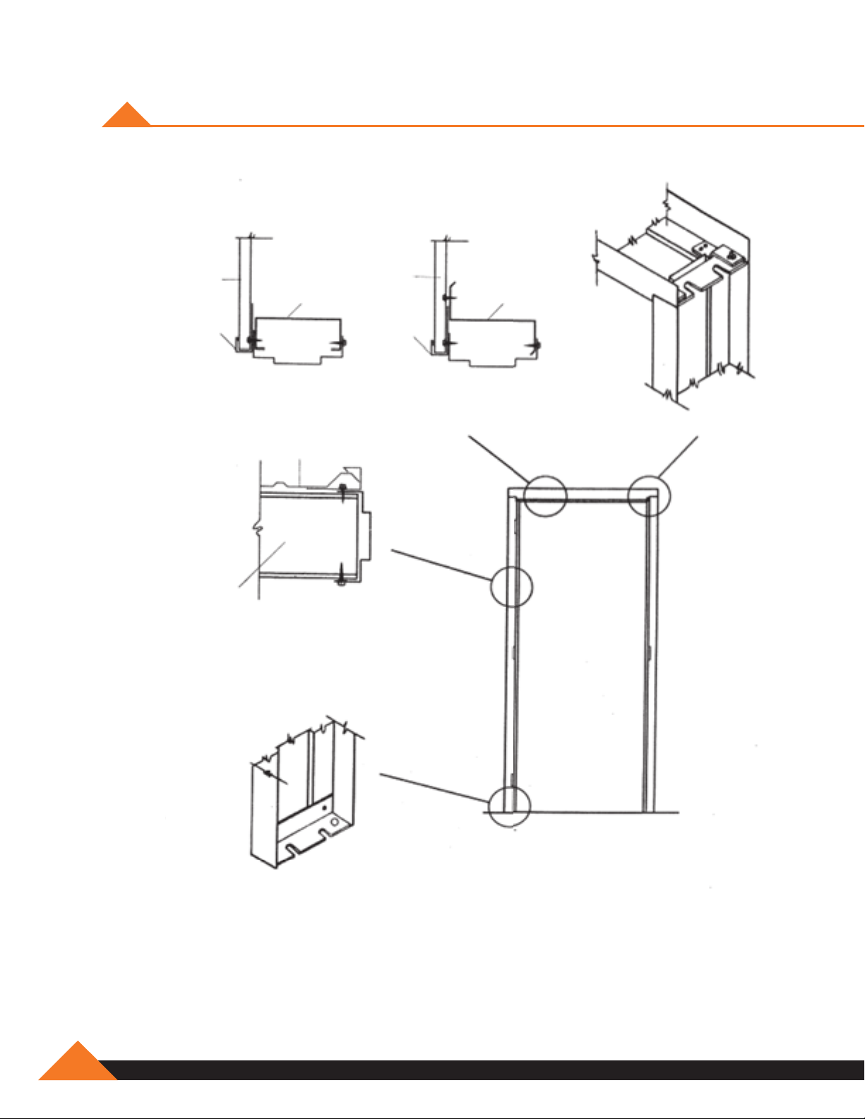
METAL BUILDING DOOR FRAME
Wall
Sheet
Door
Head
Trim
Purlin
Cee Purlin
Wall
Sheet
Door
Head
Trim
Zee Purlin
Head Section Head Section
Wall Sheet
Intermediate
Purlin Connection
Corner Connection
G-2
Standard Frame Details
No Sub-Frame Required
Sill Anchor
877-2-MUELLER
Page 95

ROLL-UP DOORS INSTRUCTIONS FOR ASSEMBLY
Included with Roll-up Doors. See Package.
See manufacturer's instructions.
WINDOW INSTALLATION
www.muellerinc.com
G-3
Page 96

VENT INSTALLATION
Roof Ventilators (Optional)
1. Ventilators may be installed on the roof ridge after the roof sheets are on and before the
ridge roll or peak sheet is installed. The ventilators are ten feet long and usually are installed
at the peak and between two rafters.
2. Cut out the ridge roll or peak sheet to fi t the opening of the ventilator. Ensure that the
opening is cut correctly so the ventilator will fi t properly and provide enough lap over the
opening to prevent leaks. (The roof sheets may need to be trimmed to maximize venting).
3. Place the ventilator over the opening. Use molded rubber outside sealers to fi ll the gaps
between the ventilator fl ange and the roof sheets.
4. Attach the ventilator to the roof sheets with lap tek screws. Screw through the vent skirt to
the tops of the roof sheet ribs.
5. Locate the vent adjusting pull chains as desired. (According to vents instructions).
G-4
877-2-MUELLER
Page 97

CONTINUOUS RIDGE VENTILATORS
10' Continuous Vent
Birdscreen
Peak Panel
Roof Panel
Outside Closure Strip
w/ Sealant Tape
End Cap
Skirt
Outside
Closure Strip
w/ Sealant Tape
Throat
Section
Throat Ga. A B C
9"
12"
26 22 12 ¾ 15 ¼
26 28 ¼ 17 ¼ 19 ½
Rain Shield
Wind Band
Interior Frame
Damper
(Optional)
www.muellerinc.com
G-5
Page 98

VENT SEALERS
End Skirt
Roof
Panel
61/2˝
Closure
Sealant Tape
Foam Closure
G-6
Peak Sheet
Roof Pitch Less than 1:12
Install the end cap for 1:12 pitch roof slope and foam closure with tape sealant top and bottom.
877-2-MUELLER
Page 99

Section B
VENT INSTALLATION
Vent
Roof Panel
Vent End Cap
Blind Rivets (4 required)
End Skirt
Fasteners
Scribe
End Skirt
Section A
Section A
Vent
End Skirt Gutter
4:12
3:12
2:12
Roof Panel
End Skirt, attach to
leading vent
Sealant Tape
Fasteners
(2 required
on each
side of vent)
Outside closure with
tape sealer top and
bottom. (Field notch
around end skirt gutter).
Section B
End Skirt
Blind Rivets (4 required)
Outside closure
with tape sealer
top and bottom.
(Field notch
around end
skirt gutter).
Roof Pitch Greater Than 1:12
End cap is factory pre-cut to 1:12. The three dots
embossed in the end cap represent 2:12, 3:12
and 4:12 roof pitches. Select the appropriate dot
to represent the roof pitch, scribe two lines from
lower corners of the end cap, intersecting at the
dot. Remove the area described by the cribe
lines and install the end skirt.
End Skirt Gutter
Remove this area
www.muellerinc.com
G-7
Page 100

PIPE DECK FLASHING INSTALLATION
1. TRIM
Cut opening to 20%
smaller than pipe
diameter.
2. SLIDE
Slip pipe flash over pipe.
3. SEAL
Apply urethane/silicone
sealant between pipe
flash and roofing.
4. FORM
Bend aluminum base to
fit irregularities. Use large
slot screwdriver to press
into tight angles.
5. FASTEN
Complete the seal using
common weather-
resistant fasteners.
Selection Chart
Master Flash
Number
1
2
3
4
5
6
7
8
Note: Numbers 1 & 3 are closed top. When using pipe flash on very steep pitched roof
or surface with deep corrugation, use next largest size for increased flange flexibility.
Pipe Size Base Dimension Opening Diameter
1
/4" - 2" 41/2" Closed
11/4" – 3" 6"
1
/4" – 4" 8" Closed
7
/8"
3" – 6" 10" 21/2"
4" – 7" 11" 31/2"
5" – 9" 12" 4"
6" – 11" 14" 5"
7" – 13" 17" 6"
Material Information
G-8
Material Neoprene EPDM Silicone
Guarantee
Temperature Range
Applicable
Tough EPDM, silicone or Neoprene
rubber resists weathering,
ultraviolet light and cracking.
Note: Specify Neoprene when Pipe Flash is to be exposed to petrochemicals.
877-2-MUELLER
10 years 20 years 20 years
-45 degree to
+200 degree
ASTM D2000,
M2 BC 510 A14,
B14, C12, F17,
Z1, Z2, Z3
-65 degree to
+250 degree
ASTM D2000,
M3 BA 510 A14,
B13, C12, F17,
Z1, Z2, Z3
Pipe opening is quickly and easily
customized on the job.
Aluminum base bends to form a
perfect seal on all roof pitches,
contours or surface irregularties.
Square flange design adapts to
any roofing material.
-100 degree to
+450 degree
ASTM D2000,
M4 GE 505 A19,
B37, C12, F19,
Z1, Z2, Z3
 Loading...