

Page 1
J6000 SERIES BREAK CHECK VALVE
Installation Instructions
NOTE: The break check valve and wet barrel hydrant must be installed and maintained according to AWWA M17,
C503, C600, and applicable local codes.
Do not use this product on wet barrel fire hydrants that have an internal diameter greater than 6-5/8"
(see Danger Tag on product for more information). Do not use break-away bolts with Traffic Flange.
BURY LINE
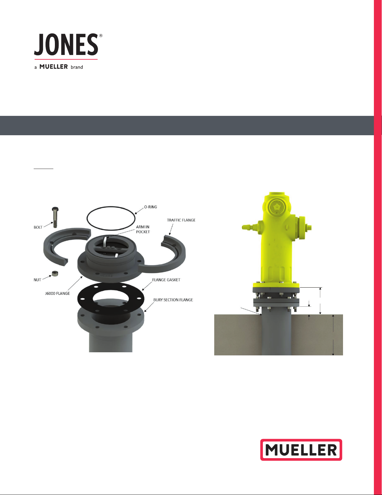
A. Upon receipt of shipment, inspect J-6000 valve assembly to ensure no damage or breakage occurred during shipment.
B. Install FLANGE GASKET onto BURY SECTION FLANGE. Set J-6000 FLANGE on BURY SECTION FLANGE; plumb, install
and tighten fasteners to pipe manufacturer specified torque.
C. Make sure the O-RING is in the O-ring groove on the traffic side of the J-6000, the Discs are vertical and ARMS are
in the J-6000 Body POCKETS.
D. Set hydrant on the J-6000 and orient the pumper to the desired direction.
6.75"
2.00"
8"
Page 2
J6000 SERIES BREAK CHECK VALVE
Installation Instructions
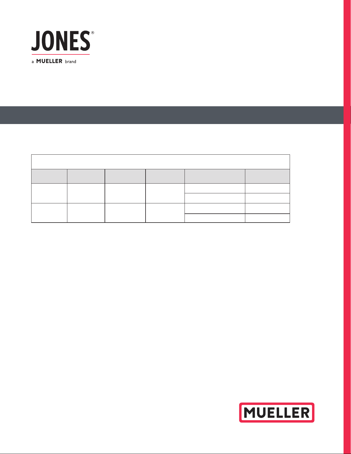
E. Attach TRAFFIC FLANGE and Traffic Flange BOLTS/NUTS (see table below) as shown.
Torque bolts to approximately 70-90 ft-lb.
HYDRANT / TRAFFIC FLANGE BOLT PATTERN
No. of Holes Bolt Hole Size Bole Circle Dia. Bolt Size Hydrant Flange Thickness Bolt Length
³₄ ˝ ³₈˝ ⁵₈˝
¹₂˝ ³₄˝
˝ ¹₄˝
or ⁷₈ ˝ ¹₂˝ ³₄˝
¹₂˝ ³₄˝
˝ ¹₄˝
* Additional Bolt Patterns may be available
NOTE: If a change in orientation of the pumper outlet is required after installation, loosen the Traffic
Flange Nuts, lift hydrant slightly and rotate using caution not to damage or displace the O-ring. Re-tighten
Traffic Flange Nuts to 70-90 ft-lb.
F. Test hydrant with line pressure before backfilling. Remove the cap from the top hydrant outlet. Slightly open
the top outlet valve and slowly open the service gate valve to restore water to the hydrant. When all air is
evacuated from the hydrant, water will begin to come out of the top nozzle. Firmly seat top valve. Completely
open gate valve and check for leaks at flanges and seals.
G. Install concrete thrust collar at or near the ground line. Recommended collar dimensions are 8 inches thick and
30” x 30” square. These dimensions are dependent upon soil conditions.
H. Flush the hydrant after installation to remove any foreign material and ensure J-6000 is set in the open
position (assure full flow is achieved)
For more information about Jones water products, please visit joneswaterproducts.com or call Jones customer service at 1.800 .423.1323.
Muelle r refers to one or mo re of Mueller Wat er Products , Inc., a Delaw are corpor ation (“MWP ”), and its sub sidiaries . MWP and each of subs idiaries are l egally sep arate and inde pendent enti ties when prov iding produc ts
and ser vices. MWP do es not provide p roducts or se rvices to third p arties. MW P and each of its sub sidiaries a re liable only fo r their own act s and omission s and not those of e ach other. MWP bran ds include Muel ler®,
Echologics®, Hydro Ga te®, Hydro-Guard®, HYMA X®, Jones®, Kraus z®, Mi.Net®, Milliken®, Prat t®, Singer®, and U.S . Pipe Valve & Hy drant. Plea se see www .mueller wp.com/abo ut to learn more .
Copyri ght © 2019 Jame s Jones Compa ny, LLC. All Right s Reserve d. The trade marks, lo gos and serv ice marks dis played in this d ocument are th e propert y of
Muelle r Water Product s, Inc., it s affiliates or o ther third par ties. Prod ucts above m arked with a sec tion symbo l (§) are subject to p atents or pate nt applicati ons.
For deta ils, visit w ww.mwpp at.com. The se product s are intended for u se in potable w ater applic ations. Plea se contact y our Mueller S ales or Custom er Service
Representative concerning any other application(s).
F 14160 10/19
 Loading...