

Page 1
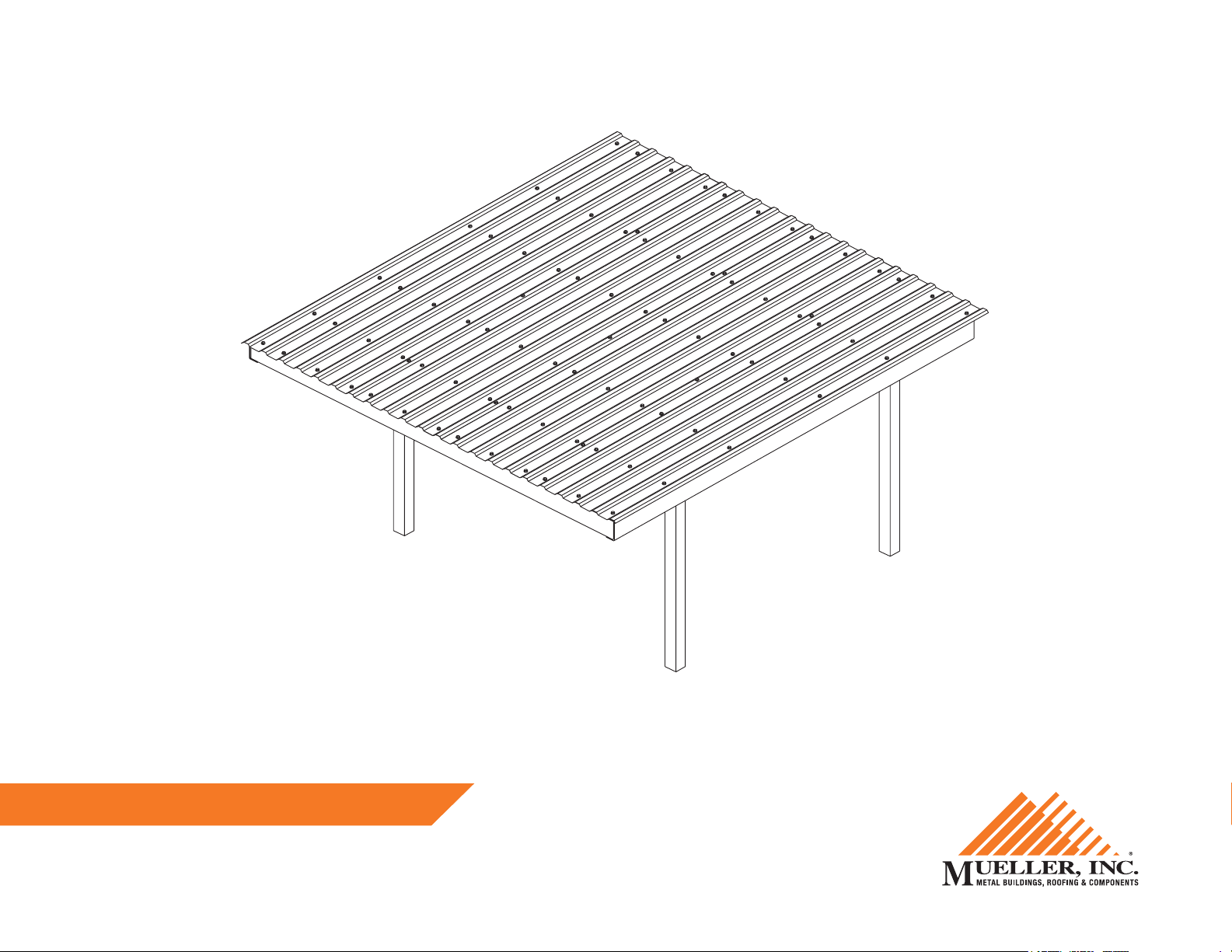
24 x 24 Carport Instructions
Mueller carports are not engineered structures and do not meet any specic building code criteria.
877-2- MUELLER • www.muellerinc.com
Page 2
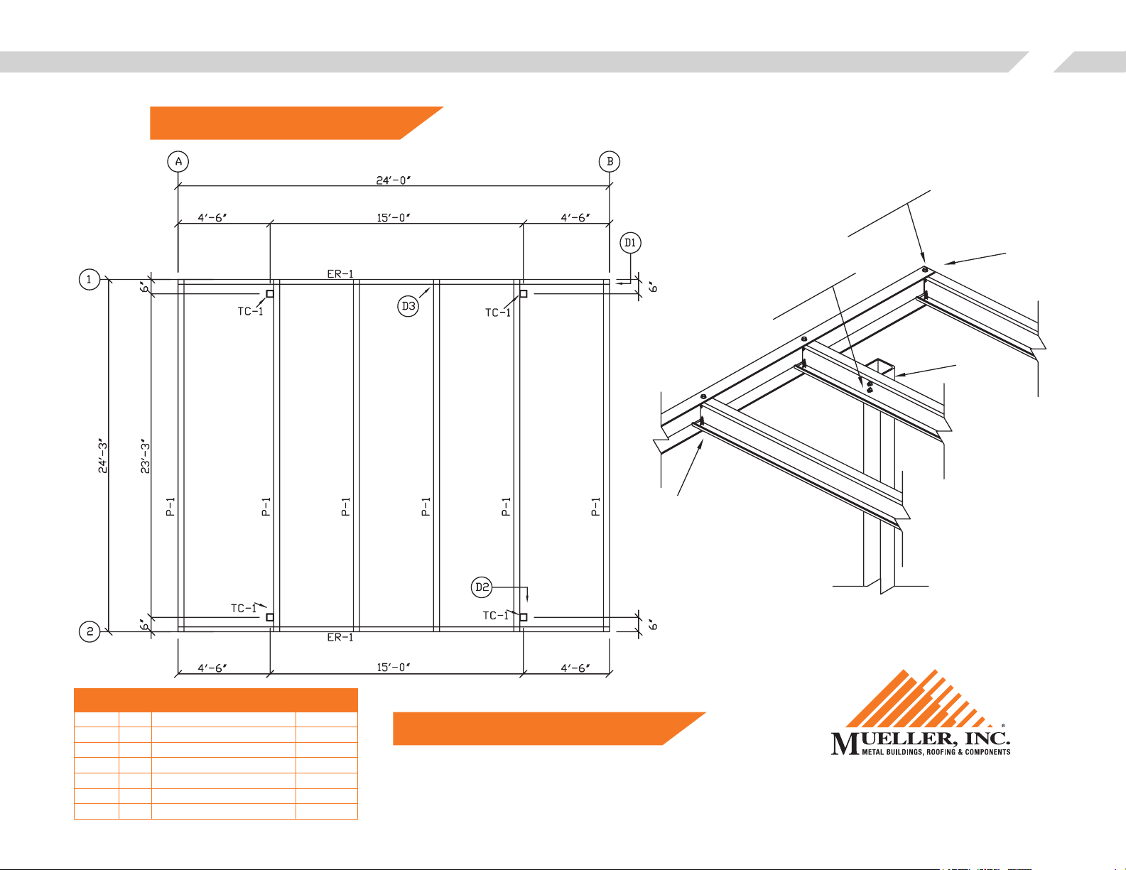
NOTE: Carport kits are not engineered.
Cap Channel
Mueller, Inc.24 x 24 Carport Instructions
½" x 1"
Flat Head Bolt
Detail D1
½" x 1"
Hex Head Bolt
Detail D2
2
List of Materials
MARK QTY DESCRIPTION LENGTH
P-1 6 8" x 2½" C-BAR 24'-2½"
ER-1 2 8" x 2 CAP CHANNEL 24'-0"
TC-1 4 4" x 4" GA SQUARE TUBE 10'-0"
8 BOLT - HEX HEAD ½" x 1"
24 BOLT - FLAT HEAD ½" x 1"
(4) (4" x 4" x 12' OPTIONAL)
NOTE: Sheets are to hang off the low side.
Detail D3
C- Bar Purlin
Tube
Square
877-2- MUELLER
www.muellerinc.com
Page 3
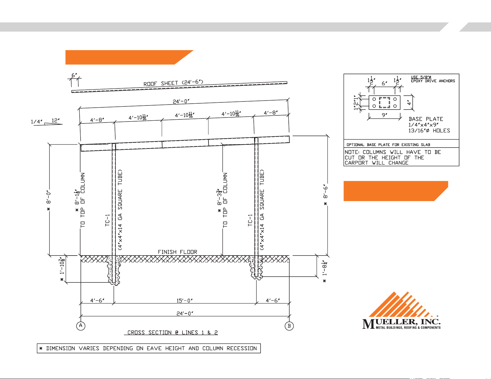
NOTE: Carport kits are not engineered.
Mueller, Inc.24 x 24 Carport Instructions
NOTE: 12' columns optional. Add 2'
to all height dimensions.
3
877-2- MUELLER
www.muellerinc.com
Page 4

Mueller, Inc.24 x 24 Carport Instructions
ALL INSTRUCTIONS MUST BE READ PRIOR TO INSTALLATION
SET COLUMNS
Spacing and elevation of the columns are critical to the proper installation of the Mueller carport. The columns
must be square, plumb and set at the exact dimensions shown on the drawings. Depending on the direction of the
watershed, the high side columns must be 2 5/8” taller than the low side columns to achieve the appropriate pitch.
Particular attention should be paid to direction of the pre-punched holes in the top of the columns as shown in the
framing drawings (Holes in column must face to the center of the carport). Pack a small amount of dirt around
each column to temporarily hold them. Do not apply concrete at this time. Time and care should be taken on column
installation, as this will directly affect the appearance and ease of installation on the rest of the carport.
4
*1'-10⅞"
TC-1
(4"x14" Square Tube)
Turn holes to the
center
TC-1
(4"x14" Square Tube)
Finish Floor
*1'-8¼"
Page 5

FRAMING
1 Turn open face of purlin to the center of carport. Align pre-
punched holes in column and purlin (P-1A) and attach with ½"
Hex Head bolts as shown.
Mueller, Inc.24 x 24 Carport Instructions
5
2 Repeat step 1 at all columns as shown in framing details.
3 Install both cap channels (ER-1) as shown in the framing detail.
End of cap channel should be 4'-6" from center of column.
Making sure the purlins (P-1A) are inserted as deep as possible
into the cap channels. Attach with bolts as shown.
4 Center purlin (P-1) is installed according to dimensions shown on
drawing, and attached with bolts as shown. Turn open face of
purlin either direction.
5 Install the high side (P-1) and low side (P-1) purlins with the open
face of purlin pointed towards the center of the carport. Insert
the purlins as far as possible into the cap channel (ER-1) and
ush with the end of cap channel to form and outside corner and
attach with Flat Head bolts as shown.
½" x 1"
Hex Head Bolt
½" x 1"
Flat Head Bolt
Page 6

Mueller, Inc.24 x 24 Carport Instructions
CROSS SQUARE THE FRAME (EXAMPLE)
Measure the frame corner to corner diagonally making sure both dimensions are the same. If not, pull the frame
square before starting sheeting. Commonly used tools are come-a-longs and ratchet straps. Squaring the frame is
critical to make the sheets run true on the frame and will affect appearance and ease of installation. Re-check level on
both P-1A purlins running column to column then add concrete and allow to dry.
6
Page 7

36"
Lap TEK
Screw
RPN Panel
TEK
Screw
TEK
Screw
TEK
Screw
TEK
Screw
TEK
Screw
TEK
Screw
TEK
Screw
2"2" 4"8" 8" 8"
36"
4"
Screw
Screw
Screw
Screw
ROOF SHEETS
Mueller, Inc.24 x 24 Carport Instructions
7
1 Place the rst roof sheet ush with the outside of the cap channel (ER-1). Overhang the high and low side
purlins equal distances, approximately 3". Optional trim package requires the roof sheets to be applied ush
with the high side purlin and all overhang is to go to the low side purlin, approximately 6".
2 Attach sheets to purlin using screw patterns shown in drawings.
3 Repeat steps 1 & 2 until all sheets are applied.
4 Lap screws are applied on 30” centers as shown in drawings.
FASTENER LOCATION AT LOW SIDE & EAVE SIDE
Lap TEK
TEK
Screw
Screw
TEK
Screw
TEK
Screw
TEK
Screw
RPN Panel
TEK
Screw
4"
TEK
Screw
TEK
Screw
2"2" 4"8" 8" 8"
FASTENER LOCATION AT PANEL INTERIOR
Lap TEK
Screw
TEK
TEK
36"
RPN Panel
TEK
12" 2"12"10"
TEK
Page 8

OPTIONAL TRIM PACKAGE
Apply as shown in trim drawings.
RAKE TRIM
½" x 1"
Flat Head Bolt
Trim
#12 TEK
Screw (Color)
Sheet
#12 TEK Screw (Color)
Cap
Channel
Mueller, Inc.24 x 24 Carport Instructions
8
#12 TEK
Screw (Color)
C-Bar
½" x 1"
Flat Head Bolt
Page 9

HIGH EAVE RAKE LOW EAVE RAKE
Mueller, Inc.24 x 24 Carport Instructions
9
#12 TEK
½" x 1"
Flat Head Bolt
#12 TEK
Screw (Color)
Trim Trim
#12 TEK
Screw (Color)
Screw (Color)
Sheet Sheet
C-Bar C-Bar
Cap
½" x 1"
Flat Head Bolt
Channel
NOTE: Sheet is to
extend 6" on
low side.
Flat Head Bolt
#12 TEK
Screw (Color)
#12 TEK
Screw (Color)
½" x 1"
#12 TEK
Screw (Color)
½" x 1"
Flat Head Bolt
Cap
Channel
Stitch
Screws
High Eave
Trim
Rake
Trim
2" x 2"
Trim
Stitch
Screws
Rake
Trim
Low Eave
Trim
2" x 2"
Trim
 Loading...