

Page 1

MODEL MTC200
Page 2
2
ITEMS REQUIRED FOR STARTUP........................ 2
FEATURES & SPECS........................................... 3
CAMERA DIAGRAMS...................................... 4-5
BATTERY INSTALLATION................................... 6
MEMORY CARD INSTALLATION.......................... 8
QUICK-START................................................... 9
ADVANCED SETTINGS .....................................10
MOUNTING & FIELD SETUP..............................16
CAMERA CARE ................................................18
TROUBLESHOOTING........................................19
WARRANTY INFORMATION..............................20
OWNER’S RECORD...........................................21
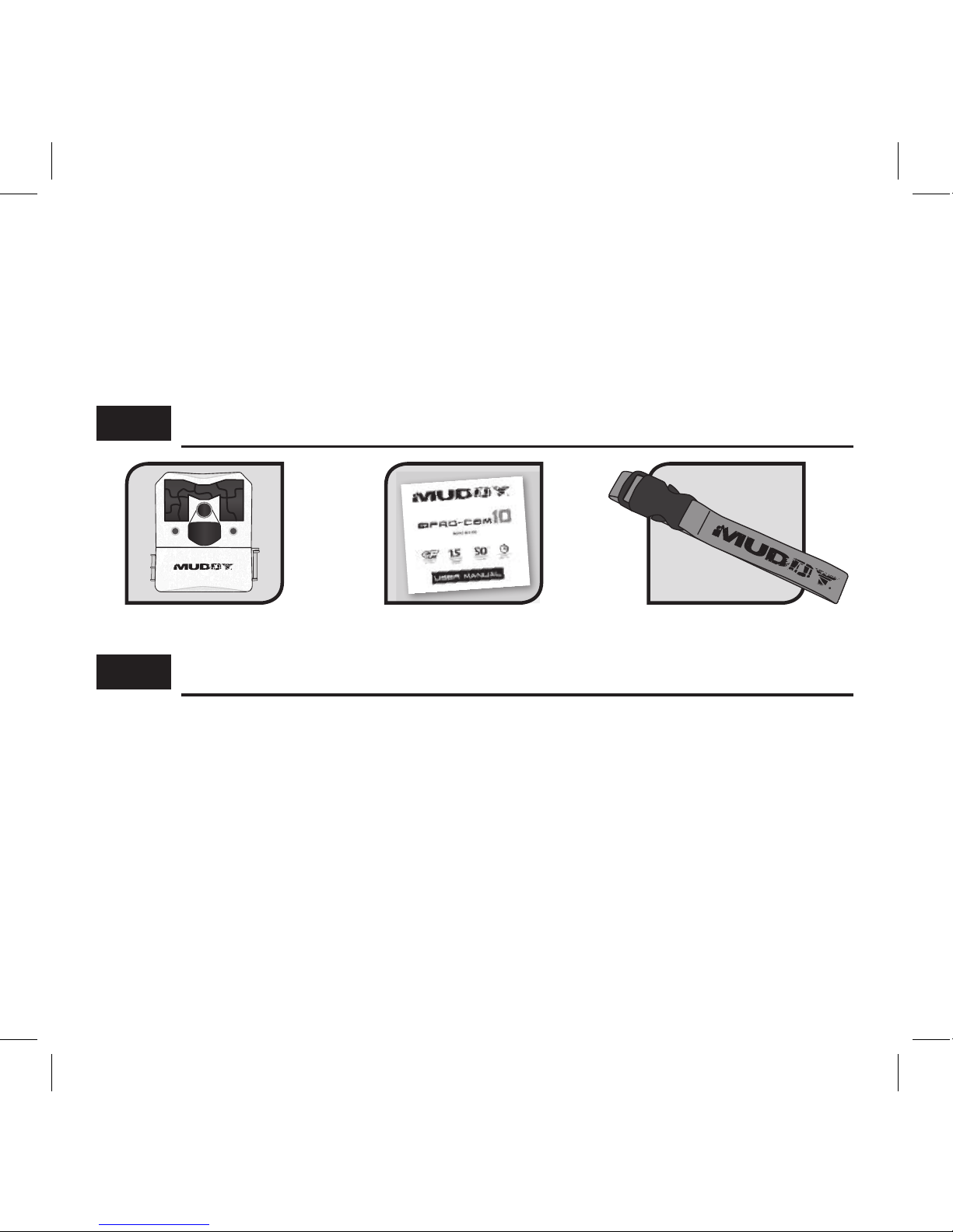
INCLUDES:
REQUIRED FOR STARTUP:
Camera Manual 5’ Mounting Strap
•
6-AA Cell Alkaline Batteries (recommend name brand for best performance, sold separately)
•
1- SDHC Storage Card (Up to 32GB) (sold separately) The Pro-Cam Trail Cameras require
a minimum of 4GB. It is highly recommended to use Class 10 SDHC Cards to provide
optimal performance.
• 1- External SDHC memory card reader for viewing photos/videos (sold separately)
NOTE: 12V DC hookup is available. Both power supply options can be used in combination
with each other. If both power supply’s are connected, the trail camera will run o of the 12V
power before switching over to the 6-AA Cell batteries. The battery indicator will display “EXT”
for the power available from the 12V DC option.
Jan. 2018. Published by Premier Outdoor Equipment, LLC., Windom, Minnesota.
© 2018 Premier Outdoor Equipment, LLC. All rights reserved
Page 3

Camera Specications
Image Res. 14 MP (Day), 2 MP (Night) Video Mode Standard VGA (32 FPS)
Image Detail Color (Day), B/W (Night) Video Length 4 Options:10 - 60 seconds
Illumination
18 LEDs with Invisible Flash Detection Range 50 Feet
Trigger Speed 1.5 Seconds Flash Range 50+ Feet
Image Data Camera ID, Date, Time, Temp, & Moon Phase
Burst Interval 2 Seconds Field of View 3 Zone + 50° Detection Angle
Camera Options - Beyond Optimal Presets
Photo Burst 2-6 Photos Trigger Delay 7 Options: 10 sec-30 Min
Physical Specs
Dimensions 4.75” H x 4.25” W x 2.5” D Settings Screen LCD Screen
Material Molded ABS Mounting Options Adjustable Strap with Buckle
Finish Non-reective Brown Alt. Mounting 1/4“ - 20
Housing Waterproof Theft Deterrence Cable Lock and Padlock Ready
Technical Data
Battery Life Up to 10,000 Images Memory Card Secure Digital Up to 32 GB
Battery Req. 6 AA Product Warranty 1 Year
Alt. Power 12V DC Operating Temp. -10° F to 140° F
FEATURES & SPECS:
3
Page 4
4
ON
OFF
M KO
OFF
O
M
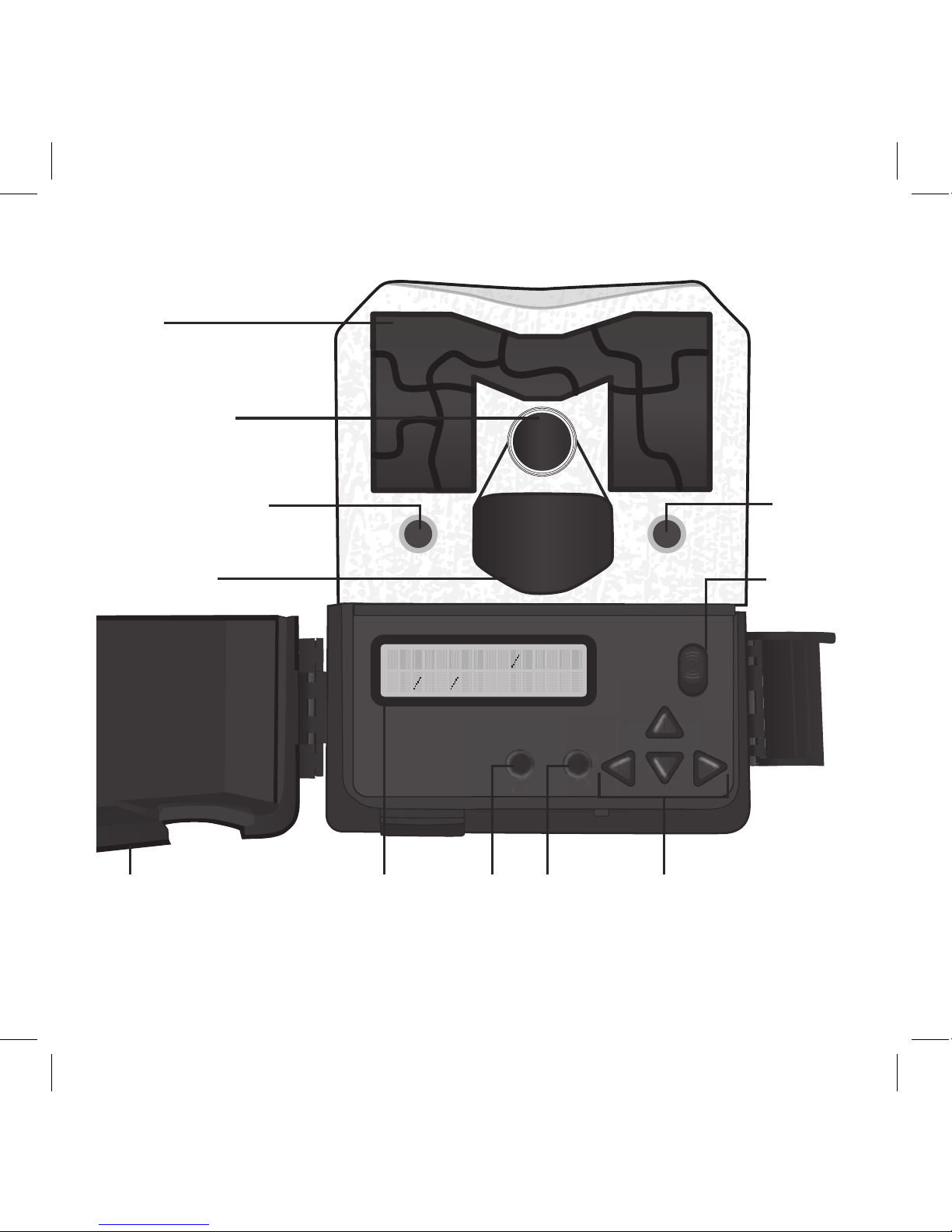
Camera Lens
LEDs
PIR Sensor
Door
Power
Button
Mode Set-up
Buttons
LCD
Screen
Ok
Motion Test LED
Light
Sensor
S E T U P D A T E T I M E
0 1 0 2 1 6 0 1 : 0 1 A M
Page 5
5
ON
OPEN
OFF
OK
M
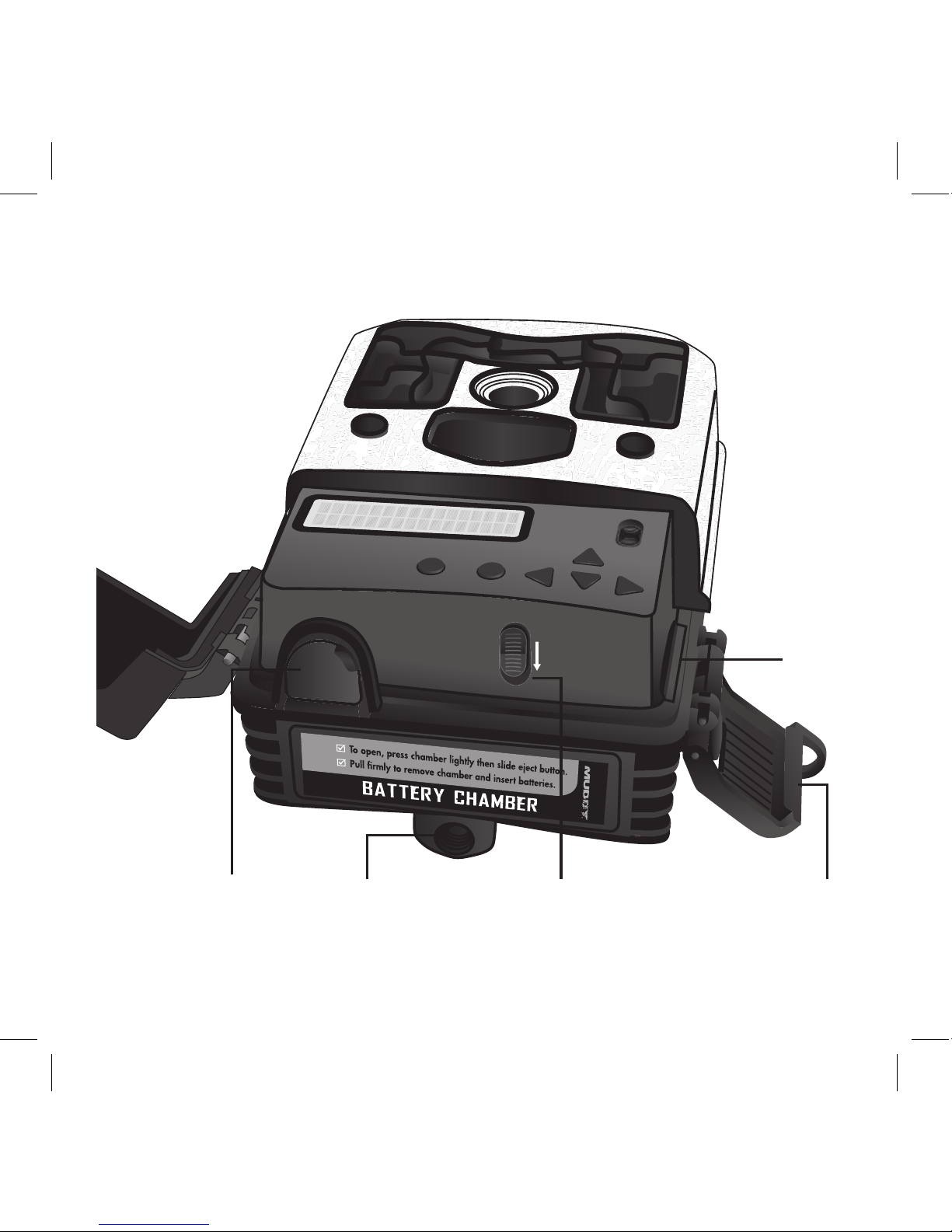
Latch
SDHC
Card
Slot
Battery Chamber
Release
Mounting Receiver
(1/4” - 20)
12V DC
Port
Page 6
6
IF USING AA - CELL
BATTERIES
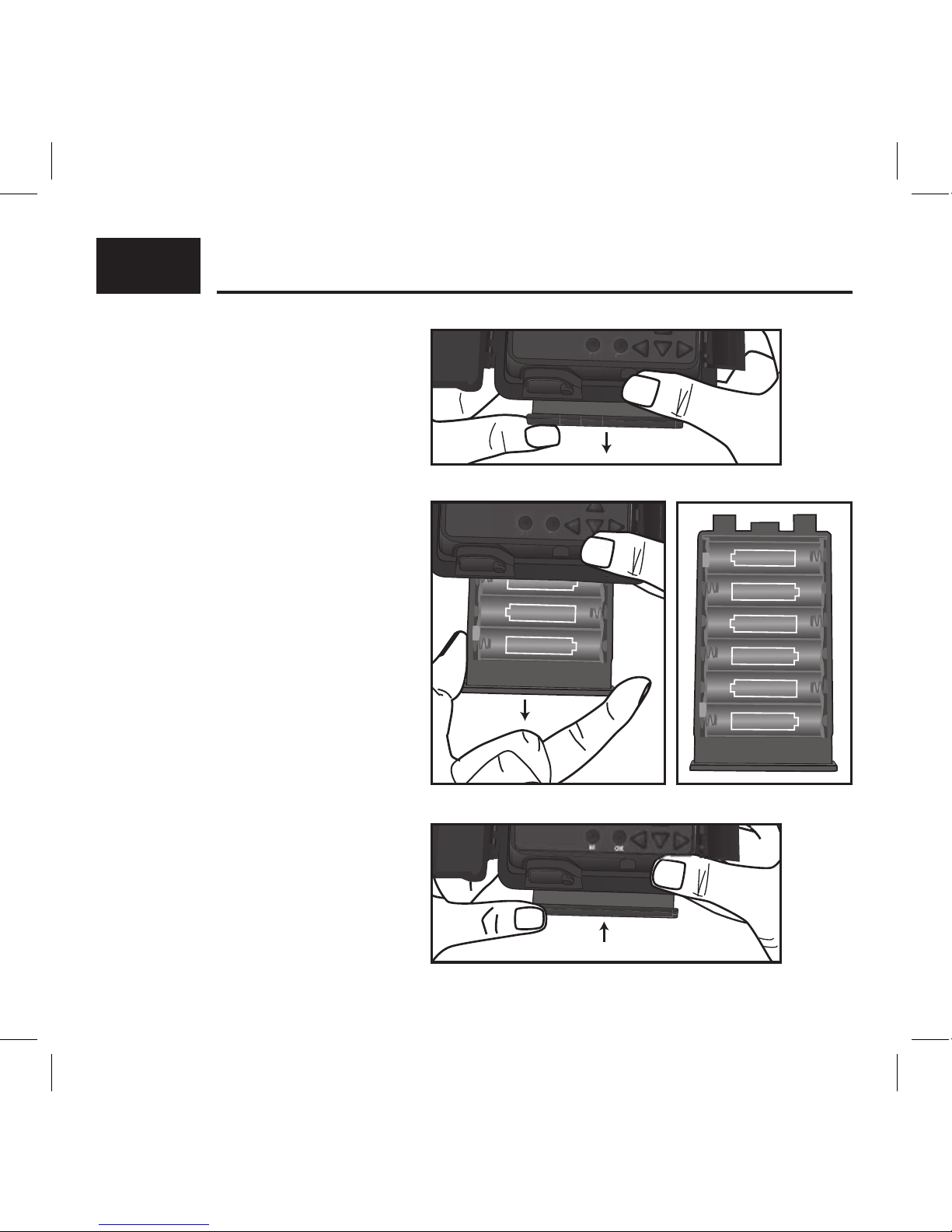
1. To remove the internal AA battery
pack, press chamber lightly and
slide the eject/open button inside
camera cover (Fig. 1). Next, pull
rmly to remove chamber and
insert batteries (Fig. 2).
2. Reference the battery icons located
on the inside of the chamber
compartment. Insert the batteries
accordingly as indicated by the
positive and negative battery icons
(Fig. 3).
3. Slide the battery compartment back
into the camera housing until it is
completely engaged in the slot in
the bottom of the housing (Fig. 4).
NOTE: Installing any of the 6-AA
batteries in the wrong direction
may cause the batteries to leak acid
and could possibly explode, causing
camera failure and damage to the
battery compartment.
INSTALLING BATTERIES:
Fig. 1
Fig. 2
Fig. 4
Fig. 3
M KO
M
OK
1.5V SIZE AA
1.5V SIZE AA
1.5V SIZE AA
1.5V SIZE AA
1.5V SIZE AA
M KO
1.5V
M
ZE AA
OK
1.5V SIZE AA
1.5V SIZE AA
1.5V SIZE AA
1.5V SIZE AA
1.5V SIZE AA
1.5V SIZE AA
Page 7
7
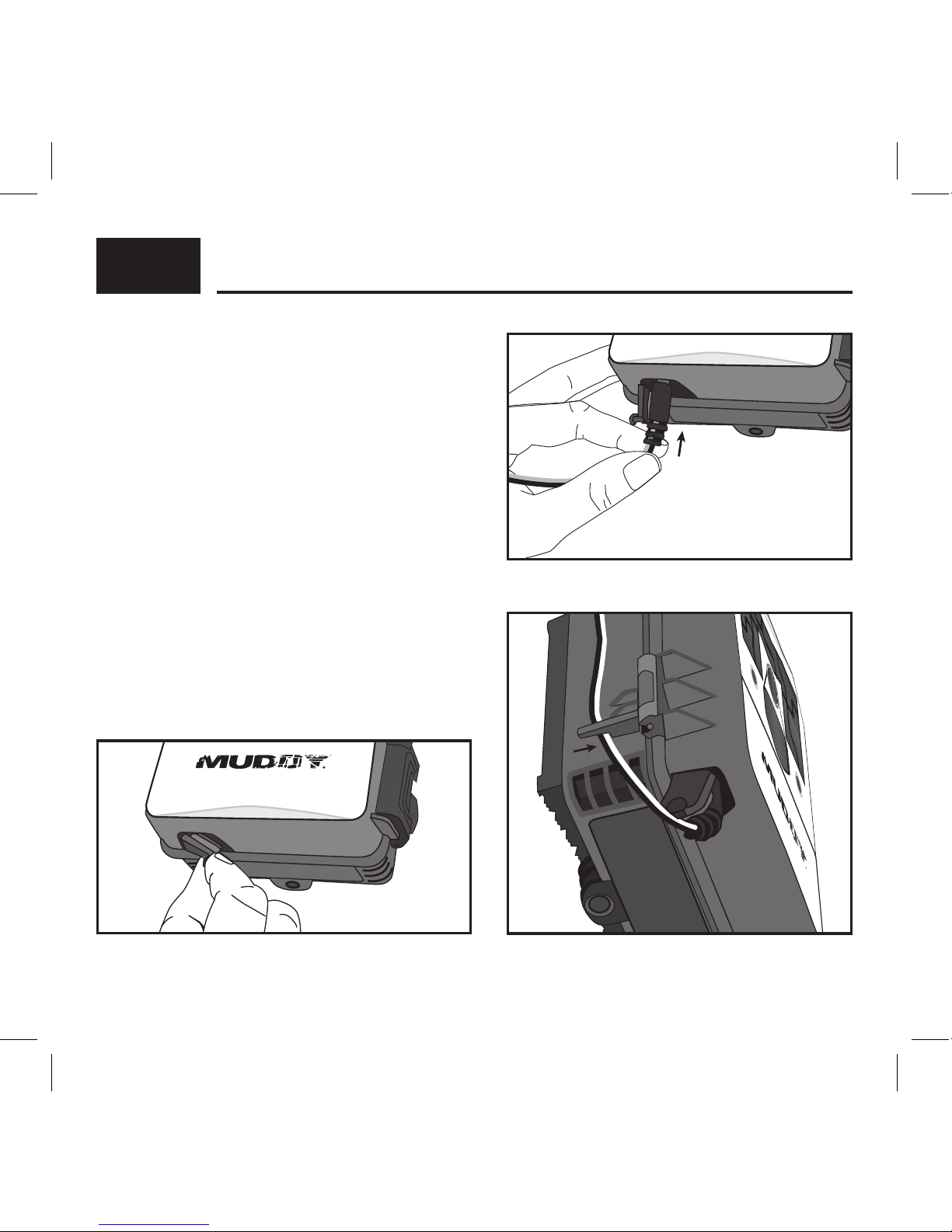
IF USING 12V DC POWER SOURCE
1. Remove the rubber port cap at the bottom
of the camera (Fig. 1). Using a universal 12V
DC cord, plug in to the bottom port option
(Fig. 2).
2. Run the cord to the side of the camera
where there is a hook provided behind the
hinge of the camera door. This will support
the power cord and take pressure o of the
connection point (Fig. 3).
3. When not in use, replace the rubber port
cap at the bottom of the camera to protect
the 12V DC universal plug-in port.
BATTERIES CONT . . .
NOTE: Make sure the camera is powered o prior to installing the batteries.
Fig. 2
Fig. 3
Fig. 1
Page 8

8
1. To access the user interface and insert a SDHC
Card, lift up on the side locking latch located
toward the bottom of the side of the camera.
After the latch is disengaged, move latch to
allow the interface door to open (Fig. 1).
2. Insert the SDHC card with the contacts facing
away. The SDHC card should slide in freely
with little resistance. Continue pressing the
card inward until you hear a click. This means
the SDHC card is locked in place and ready for
use. (Fig. 2).
3. To remove SDHC card, press the card inwards
to release.
NOTE: We do NOT recommend using cards
that came out of a camera from a dierent
manufacturer, or one that has previously been
used in a point and shoot camera. Doing so,
your Pro-Cam might not be able to accept or
read the SDHC Card properly. Use the Format
SDHC Card function on the camera for a full
format before each use (after you have either
copied or reviewed all your photos, see page 17
for reviewing photos), or if any problems occur.
Another option is a full format on a PC. Formatting
a SDHC card clears le system corruption and
erases everything on the SDHC card.
MEMORY CARD INSTALL:
CARD
Fig. 1
Fig. 2
(sold separately)
Page 9

9
Your Pro-Cam will come with the following standard options already preset. You can leave all
settings as defaulted to start taking quality pictures, but you’ll want to make sure to set up
the current Date and Time.
Setup date/time (Defaults to original date/time – may need to be re-programmed if you reset
the default settings)
CAMERA MODE – CAMERA
BURST MODE – 3 PHOTOS
IMAGE QUALITY - HIGH
PICTURE DELAY - 10 SEC
VIDEO LENGTH - 10 SEC
FLASH MODE - AUTO
CAMERA ID - MY CAMERA
TEMPERATURE UNIT - FAHRENHEIT
PICTURE INFO BAR - ON
QUICK-START:
Page 10

10
Slide the power button from OFF to ON position to activate the camera and view the user
setup screen.
Setting the functions is easy;
1. Simply press the M button to access the menus, and use the UP or DOWN arrows to scroll
through the menu settings.
2. To select the menu setting you want to adjust, press the OK button.
3. Make your adjustments, and press OK button to accept the settings and change to another
menu.
*Note: any changes you make to settings are not saved until you hit the OK button. If you
power the camera o prior to hitting the OK button, settings will remain unchanged.
TIME AND DATE:
Sets the Date, Year, and Time of day to be imprinted on your photos (not video).
Press the OK button for the month setting to ash. Use the UP and DOWN arrows to change.
Press the LEFT or RIGHT arrows to move to the DATE and set this accordingly. Next, press
the LEFT or RIGHT arrows to move
to the year and set accordingly.
Continue to adjust the hour,
minute, and am/ pm on the time.
Press the OK button when nished,
and press the UP or DOWN arrows
to go on to another menu.
ADVANCED SETTINGS:
ON
OFF
M KO
OFF
O
S E T U P D A T E T I M E
0 1 0 2 1 6
0 1 : 0 1 A M
Page 11

11
CAMERA MODE:
Sets the camera to take either photos or videos.
CAMERA - The following other settings are
recommended to be set when in Camera
Mode: Image Resolution, Picture Delay, Burst
Mode, Flash Mode
VIDEO - The following other settings are
recommended to be set when in Video Mode:
Video Quality, Video Length
BURST MODE:
Sets how many images the camera will take in a
row before the trigger delay kicks in. The amount
of time between burst photos is 2 seconds.
Options are: 2–6 photos, OFF
Example: Setting the camera to 3 PHOTO will
give you 3 photos, 2 seconds apart
IMAGE QUALITY:
Sets the quality at which you would like the
camera to take the pictures. Setting your
Pro-Cam to low will allow you to store more
images on the SDHC card, at a lower quality. The
high setting will allow the highest quality images
but requires more storage space.
Options are: HIGH, MEDIUM or LOW
CAME RA MODE
CAM E R A
3 P H O T O
B U R S T M O D E
I M A G E Q U A L I T Y
HIG H
Page 12

12
PICTURE DELAY:
Selects the trigger delay at which you want
to run your camera. This is the amount of
time between each trigger the camera takes.
Options are: 10 sec, 20 sec, 30 sec, 1 min,
5 min, 10 min, 30 min
On a lower setting, the camera will trigger more
often than when a higher delay is selected.
VIDEO LENGTH:
Selects the length you would like each daytime
video to be. All night videos are 10 seconds in
length, this is to ensure maximum battery life.
Options are: 10 sec, 20 sec, 30 sec, 1 min
FLASH MODE:
Gives you the option to have the camera
automatically use the Invisible Flash LEDs when
necessary, or o.
Options: AUTO or OFF
Turning the ash mode o will trigger photos
during hunting hours only, which can extend
your battery life and save storage space.
P I C T U RE DEL AY
1 0 SEC OND
V I D E O LEN G TH
10 SEC O ND
FLASH MODE
AUTO
Page 13

13
FW VERSION:
Displays the version of rmware that is installed
on the camera.
MOTION TEST:
Allows you to determine distance and aim for
your detection zone. When this setting is on,
you can walk to your target area and move
around. The red detection LED will light up
when the camera detects you. The camera
will arm when it does not detect motion for
30 seconds.
DEFAULT SETTING:
Resets all of the menu settings back to default.
Reference page 9 for Quick Start default settings.
FW V E R S I ON
X X X X X X
X
MOT I ON TES T
DEFAULT SETTING
NO
Page 14

14
FORMAT SDHC CARD:
Allows you to format your SDHC Card.
Formatting a SDHC card clears file system
corruption and erases everything on the
SDHC card. NOTE: Before each use, it is highly
recommended to either perform a full format
on the SDHC Card via a PC, or by performing
the Format option on the trail camera.
CAMERA ID:
Gives a name to your trail camera that will imprint
on the photo les (not video).
TEMPERATURE UNIT:
Imprints the current temperature on your photo
les (not video).
Options: Fahrenheit or Celsius
F O RMA T S D CAR D
NO
C A M ERA I D
MY C AME RA
TEMPER ATU R E U N I T
F AHR E N H E I T
Page 15

P I C T URE I N FO B AR
ON
15
PICTURE INFO BAR:
This setting is only available in Camera Mode,
not Video Mode.
It allows you to choose if you want the photos
to have the current information imprinted on
your les or not.
Info included on bar:
MOON
CAMERA ID PHASE BURST TEMP DATE TIME
Page 16

Loop
Latch
Fig. 3
Cable
Track
Mounting
Receiver (1/4” - 20)
Strap Slot
Fig. 2
F
ig. 1
16
Your Pro-Cam trail camera comes with a 5’ nylon
mounting strap which allows for quick and easy
mounting (Fig. 1). The camera has an open slot
on each side of the back for your strap to thread
through for mounting. There is also a cable track
formed in the back of the camera for additional
cable securing (cable sold separately). The bottom
of the camera features a ¼”-20 mount receiver to
attach to various Muddy mounts (MTCA-TCS03 Dual
Camera Ground Mount, MTCA-TCS02 Adjustable
Trail Camera Support, sold separately) (Fig. 2). Your
Pro-Cam trail camera also has a loop in the latch for
padlock security (padlock sold separately) (Fig. 3).
Once you have your trail camera mounted
where you want it. Be sure you run the “Motion
Test” function on your camera for proper aim
and distance. See page 13 for more info.
The motion detection angle of your Pro-Cam
trail camera is about 50 degrees, which is slightly
wider than the camera Field of View. The motion
detection distance in ideal conditions is 50 feet.
This can be greatly aected by weather conditions,
animal body size, and speed at which an animal
passes through the detection zone.
MOUNTING & FIELD SET-UP:
Page 17

17
Your Pro-Cam trail camera will arm itself to take pictures when powered on, with no button
activity for 30 seconds, and on the home screen. After 30 seconds, the camera is armed and
ready to take pictures. The camera will arm itself in 90 seconds with no activity and in the
camera menu.
You can also quickly activate the camera by pressing the RIGHT arrow from the main startup
screen. This will start a 3 second delay. At which point, the camera will be armed and ready
to take pictures.
The easiest way to review the images on your SDHC card, is to insert the card into a
home computer.
Some computers will have a SDHC slot equipped, where you can directly insert and view
the images.
If your computer does not come equipped with an SDHC slot, you will need to purchase
an SDHC Card Reader. These are inexpensive, and can be found at your local electronics/
hardware store.
ARMING THE CAMERA:
REVIEWING IMAGES:
Page 18

18
Moisture, vibration, and extreme temperature can cause severe damage to your trail camera
and should be avoided. Keeping your camera free from moisture and vibration and using in the
correct temperatures will assure you many years of maintenance free service and operation.
MOISTURE:
Although the Pro-Cam trail camera has a very durable waterproof membrane inside the
molded ABS material shell, care must be taken to prevent water damage.
• NEVER mount your trail camera upside down or leave the case open for an extended period
of time.
• NEVER change batteries, camera settings, or SDHC Cards in heavy rain.
• If your camera would happen to get water inside, remove the batteries immediately and allow
the camera to dry out for several days before activating it.
VIBRATION:
Like any electronic device, your Pro-Cam trail camera is designed with many small electronic
components that are very sensitive to vibration. Failure to follow careful handling and transport may cause extreme and irreparable damage to your camera.
• NEVER drop the camera on a hard surface
• ALWAYS transport your camera in a method to avoid bouncing around or vibration
TEMPERATURE:
Recommended storage and operating temperature: -10°F to 140°F. NOTE: Battery life and
functions may discontinue or experience shortness in extreme cold/warm temperatures
• NEVER store your camera in a vehicle or other contained environment with extremely high
temperatures for an extended period of time!
CAMERA CARE:
Page 19

19
CAMERA NOT RESPONDING: If your camera at any time does not respond when powered
on, or you cannot power it o, your camera may be locked up. The best way to resolve this
problem is to remove the AA battery compartment for a period of 10 seconds. This will cut
the main power supply to the camera and will take care of the problem. If you are using an
alternate power supply, remove any connections for a full 10 seconds.
BAD SDHC CARD: Over time a SDHC or any storage device could become corrupt. If your
camera fails to acknowledge the SDHC card, we recommend that you replace the card with
a new SDHC card or one from a dierent MUDDY trail camera that you know works. This will
help determine whether the problem is the SDHC card or the camera. We do NOT recommend
using cards that have been used in cameras from dierent manufactures and/or dierent
styles of cameras unless a Full Format on a PC is done to those cards.
NOTE: If you used a Point and Shoot camera to view your pictures and videos on the SDHC
Card, this may cause problems when inserted back into your trail camera. It is recommended
to do a Full Format on a PC before it goes back into the trail camera.
IMAGE QUALITY: Your Pro-Cam is designed to give you optimum trigger speed, along with
great night photo clarity. There may be some instances where an animal is moving extremely
fast or light conditions may be insucient, causing a smearing/blurry object within your
image. This is a natural part of photo taking and may occur from time to time.
TROUBLESHOOTING:
Page 20

20
WARRANTY
Muddy Pro-Cam Trail Camera’s 1 Year Limited Warranty: For a period of 365
days after purchase, Muddy will, at its discretion, repair or replace this product for
any reason of any defect or malfunction. This warranty is only valid if the product is
used for the purpose intended and has not been tampered with and/or physically
damaged in any way. Products that have been damaged due to negligence
or misuse do not qualify for warranty replacement. Proof of purchase must be
provided to be eligible for warranty.
WARNING! Prolonged exposure from looking directly into any infrared light could
cause cataracts or permanent retinal damage. Do not look directly into the camera during
test mode! Failure to follow this warning may cause serious injury or blindness!
WARNING! Do not expose camera interior components, batteries, or SDHC card to
rain or water. Make sure camera and hands are completely dry before handling. Failure to
follow this warning may result in serious damage to the camera and/or its parts, personal
electri cal shock or death!
WARNING! Only batteries as designated in this manual should be used. Failure
to follow this warning may result in leaking batteries, serious damage to the camera, and
personal injury or death!
WARRANTY:
-
Page 21

21
Product Name
Model Number
Serial Number
Purchased From
Purchased Date
OWNER’S RECORD:
Page 22

Page 23

Page 24

Premier Outdoor Equipment, LLC.
PO Box 454 , Windom, MN 56101, Toll Free: 844-745-7723
 Loading...