

BlueBox 150 RO Wall
Operating manual
PURE WATER – ANYTIME – ANYWHERE
ON / OFF
BlueBox 150 RO Wall
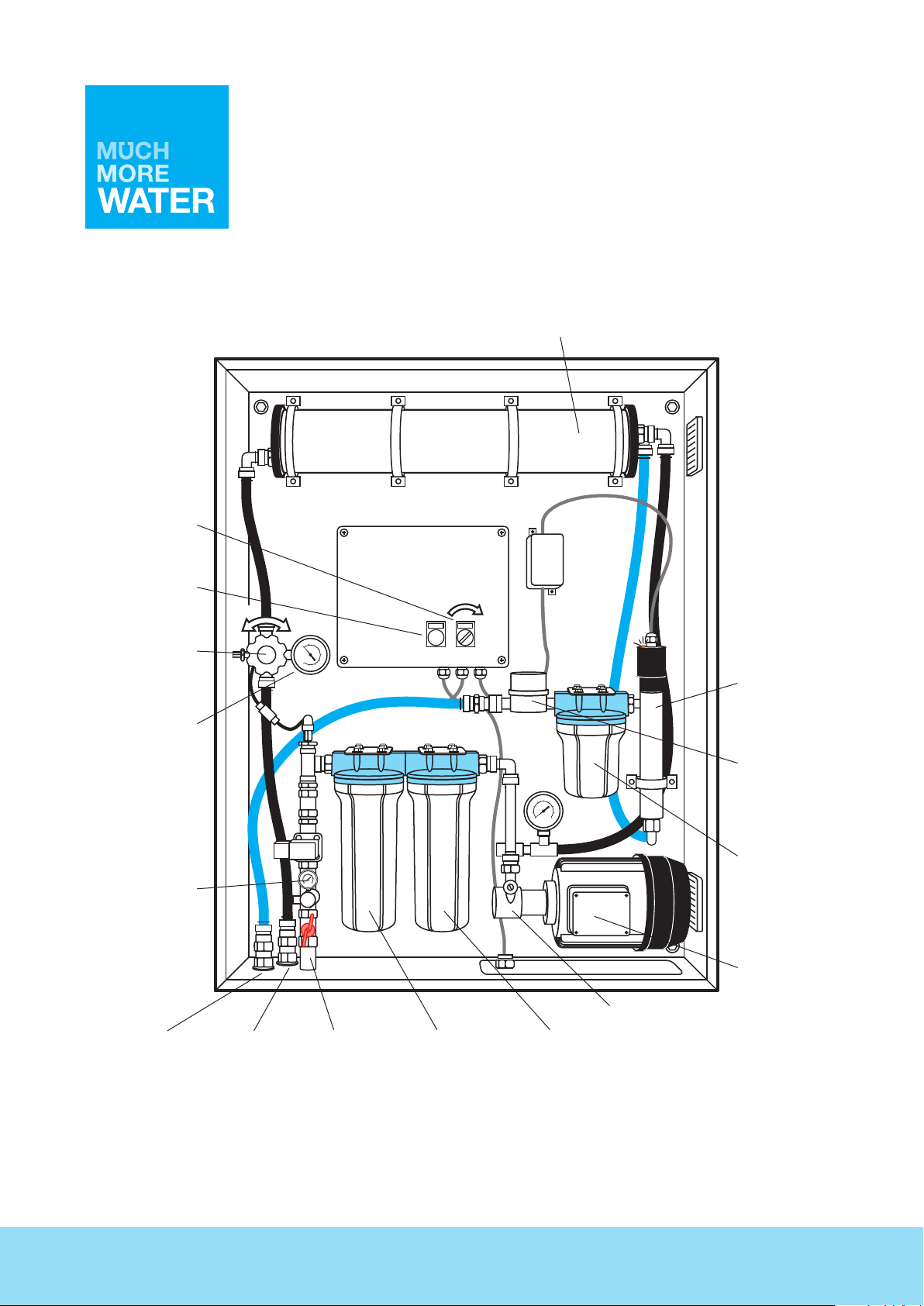
RO membrane
UV-LIGHT
Solenoid valve/
System primer button
Adjustment valve
Pressure valve
Pressure gauge
ON
8 BAR0 BAR
2
4
0
6
50
0
100
8
150
250
200
10
16
12
14
SOLENOID
OFF ON
VALVE
UV-light
Water meter
8
10
6
100
12
150
4
50
200
14
2
250
0
0
16
3
2
4
5
1
6
0
Activated Carbon
filter housing
Motor
Pump
Clean
water outlet
(blue hose)
2
Flush
water outlet
(black hose)
PURE WATER – ANYTIME – ANYWHERE
Raw
water inlet
(steel pipe)
5 micron
filter housing
Activated Carbon
filter housing

INTRODUCTION
The BlueBox150 RO wall mounted water purifier from MuchMoreWater A/S is a device for purifying nonpotable water from centralised (public) water distribution supply grids into pure drinking water. The system
is designed for rack-mounting onto a suitable wall.
The BlueBox 150 RO Wall will provide approximately 150 litres per hour of pure drinking water.
The unit is delivered ready for operation; only leaving wall-mounting, connection to power and water inlet,
as well as water outlet.
This guide provides important information on setup, operation, and shut-down procedures.
MuchMoreWater recommend reading this guide carefully before taking the system into operation.
Feel free to contact our support team or your local contact for clarifications and assistance.
DISCLAIMER
• The BlueBox150 RO Wall purifier is not designed for heavily polluted water sources, such as untreated water from water holes. The equipment is designed for connecting to the existing water
distribution network. Using this equipment for other water sources can damage the equipment, and
lead to change of critical parts, such as the pump, filters and membrane.
• The BlueBox150 RO Wall is not for sea water or water with salinity levels over 1500 PPM (mg/l).
• The BlueBox150 RO Wall must be fed fresh water at all times. Dry-running the pump can create
serious damage to the pump.
• Only a skilled technician should open the control unit. Risk of high voltage, which can damage your
health.
• Daily maintenance of the particle filters must be undertaken for optimal performance. Allowing the
particle filters to clog up poses a serious risk of damaging the pump and membrane.
• Do not operate the system without particle filters. Neglecting to operate with particle filters can
seriously damage the RO membranes.
• Only water coming out of the appropiately labelled outlet is drinkable.
Do not drink water from the flush water outlet pipe.
3
SOLENOID
VALVE
OFF ON
ON
UV-LIGHT
0
0
50
100
150
200
250
2
4
6
8
10
12
14
16
SOLENOID
VALVE
OFF ON
ON
8 BAR0 BAR
0
0
50
100
150
200
250
2
4
6
8
10
12
14
16
UV-LIGHT
OFF ON
ON
UV-LIGHT
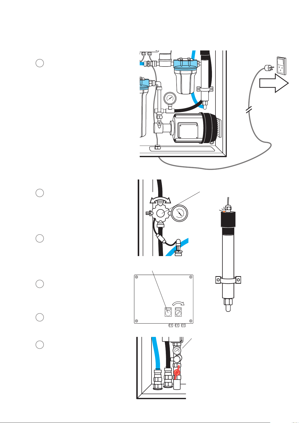
PART 1 STARTING THE BLUEBOX
1
Mount correct electrical plug
to the supplied mains wire.
Connect the unit to a 230 V
power supply.
8
10
6
100
12
150
4
50
200
14
2
250
0
0
16
2
Before starting the pump, the
blue pressure valve must be
opened by turning it all the
way counter-clockwise to
0 BAR.
3
Please ensure that the UV-
light and glass tube has been
installed prior to operationg the
unit and that the LED light is
activated.
4
Press the solenoid valve button
until you can see water coming
out of the Flush water outlet.
5
Turn the black power switch
clockwise to the ON position.
6
Ensure that the pressure of
inlet water is at min. 2.5 bar
(400l/h)
Solenoid valve
Pressure valve
8 BAR0 BAR
2
4
0
6
50
0
100
8
150
250
200
10
16
12
14
Ensure UV-light
and glass tube are
installed
SOLENOID
OFF ON
VALVE
Min. 2.5 bar
3
2
4
5
1
6
0
4
SOLENOID
VALVE
OFF ON
ON
0 BAR
UV-LIGHT
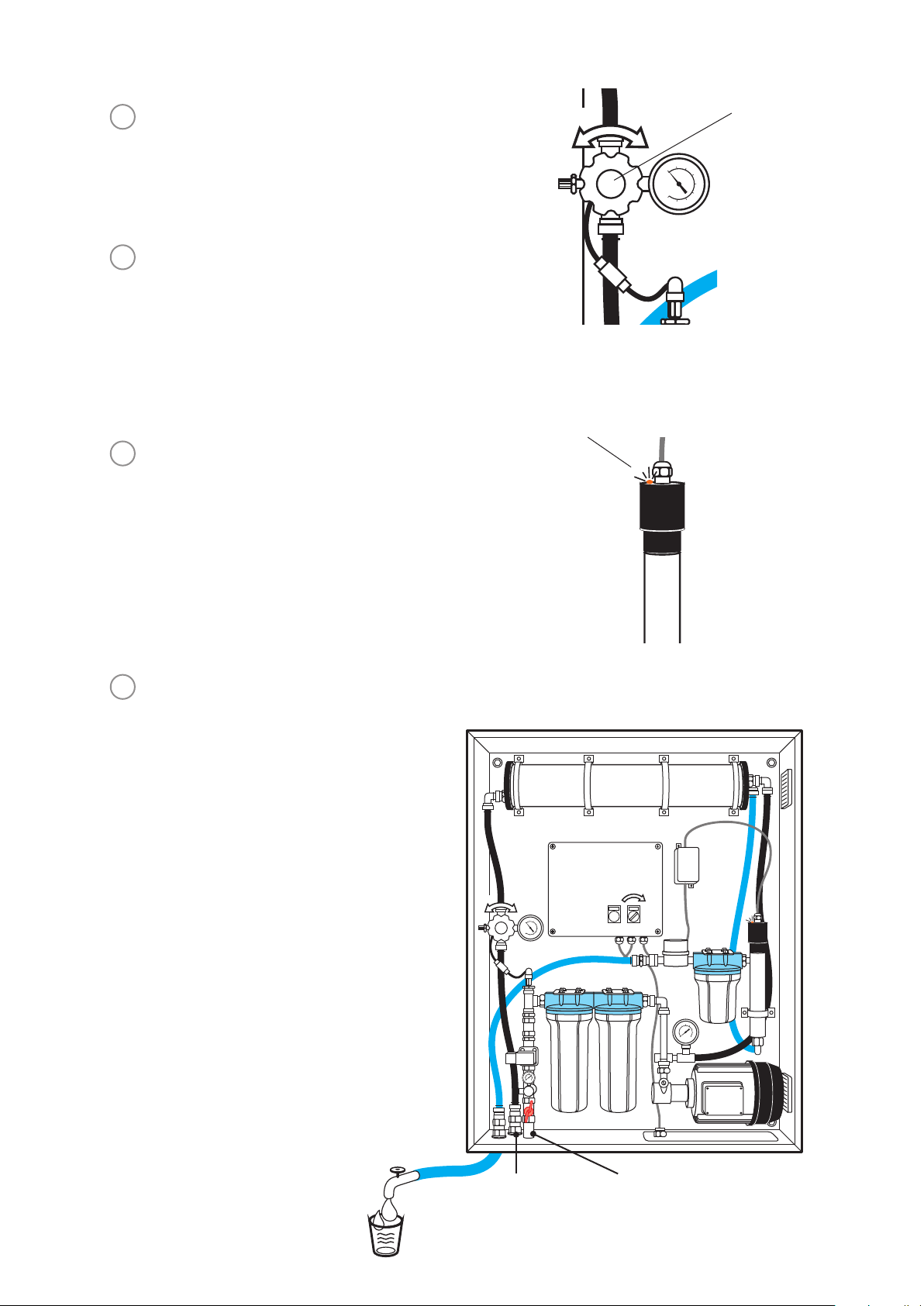
5
Let the pump run for 1-2 minutes
until no more bubbles are
detected from the red hose.
6
Turn the blue pressure valve
clockwise until pressure is
approximately 8 bars.
7
Check that the UV lamp is active,
indicated by the LED light located
at the top of the UV-light housing.
The UV light must be changed
after 365 days of operation.
Please see maintenance section.
UV-lamp
8 BAR
Pressure valve
2
4
0
6
50
0
100
8
150
250
200
10
16
12
14
8
Non-potable (not suitable for
drinking) water will come out of the
black hose (Flush water outlet).
Drinking water can be tapped from
the blue hose (Clean water).
The flow meter shows the volume
of clean water.
WARNING!
Never drink the water from the
blue fresh-water tube before the
BlueBox has been working for at
least 3-5 minutes!
UV-LIGHT
8 BAR0 BAR
2
4
0
6
50
0
100
8
150
250
200
10
16
12
14
3
2
4
5
1
6
0
ON
SOLENOID
OFF ON
VALVE
8
10
6
100
12
150
4
50
200
14
2
250
0
0
16
Clean water outlet
Flush water outlet Raw water inlet
Wait 3-5
minutes
5

OE ring
SOLENOID
VALVE
OFF ON
ON
8 BAR0 BAR
0
0
50
100
150
2
4
6
8
UV-LIGHT
PART 4 MAINTENANCE
Daily
1
Cleaning of the three filters
cartridges:
a) Screw off the three filters
housings using the supplied tool.
b) Remove the filter from the
housing and rinse both with clean
water.
IMPORTANT
The filters must NOT be wrought
or squeezed.
250
200
10
16
12
14
2
3
1
8
10
6
100
12
150
4
50
200
14
2
250
0
0
16
3
Grease the OE rings lightly before reinstalling the used or new filter cartridges in the housings
and screw them back onto the sockets.
4
The filters should be changed when plant pressure is becoming too high or when they are
3
2
4
5
1
6
0
judged to being too dirty. Max. 6 months operating time.
5
The air filter mounted in the door of the electrical cabinet must be inspected every day ensuring
the filter is not clocked.
6

EVERY MONTH
• Check that all the connections and clamps are tightened correctly.
• Ensure that filter cartridges, membranes and UV-light bulb are fittet correctly.
• Check that the drainage pipes in the container are not blocked.
• Check all hoses for holes, tears and other signs of damage and water leakage.
• Check the pump’s membrane. If there is water leaking out of the small hole at the bottom of
the pump, the membrane in the pump is not watertight and must be changed.
EVERY YEAR
We recommend that the UV glass tube is removed from the chamber and cleaned using a damp
cloth infused with a solution of a mild cleaning agent.
PUMP MAINTENANCE
The membranes must be renewed once a year.
1
Remove the two bolts on top of the motor and replace filter.
2
Remove the four bolts either side of each cylinder and replace filter.
3
Assemble in reverse order.
IMPORTANT
The BlueBox 150 RO must be started every 3 months in order to maintain flexibility in rubber
parts and to avoid build up of contaminants.
Ensure to drain the unit before storing it away.
7

PART 5 CLEANING
ON
8 BAR0 BAR
2
4
0
6
50
0
100
8
150
250
200
10
16
12
14
SOLENOID
OFF ON
VALVE
UV-LIGHT
8
10
6
100
12
150
4
50
200
14
2
250
0
0
16
3
2
4
5
1
6
0
FLOW
CLEAN WATER
PUMP
After more than 14 days of standstill and before storing, the BlueBox 150 RO Wall must undergo a
complete cleaning process.
To clean the unit, plug in an external pump to the black hose as indicated in this illustration.
Run for 15 min. Reconnect the black hose and run the system for 5 minutes.
Please ensure that you have approximately 50 litres of clean water available before you start the
cleaning process.
8

OE ring
Cleaning procedure with Sodium Hydroxide and Nitric Acid
(For example RoClean P303 and RoClean P111)
1
Un-screw the three filter housings and pull out
the filter cartridges. Screw the filter housings
back onto the mounts without the filters in.
2
Acid Cleaning (RoClean P303)
Dilute 200 gsm of RoClean P303 in 10 litres of
water.
Insert all three hoses into the container with
the cleaning fluid (Flush water outlet, Raw
water inlet and Clean water).
Start the BlueBox and let the system rinse
without pressure (open the blue pressure
valve) for 10 minutes.
3
Turn the blue pressure valve clockwise to
show approximately 8 bars of operating
pressure.
Run the BlueBox at this setting for 30 minutes.
4
Open the pressure valve all the way and run the system with clean water for 10 minutes
without pressure, and then again for 10 minutes with 8 bars of pressure.
2
1
3
5
Alkali cleaning (RoClean P111)
Dilute 200 gsm of RoClean P101 in 10 litres of water.
Insert all three hoses into the container with the cleaning fluid (Flush water outlet, Raw water
inlet and Clean water).
6
Start the BlueBox and let the system rinse without pressure (open the blue pressure valve) for
10 minutes.
7
Turn the blue pressure valve clockwise to show approximately 8 bars of operating pressure.
Run the BlueBox at this setting for 30 minutes.
8
Open the pressure valve all the way and run the system with clean water for 15 minutes
without pressure, and then again for 15 minutes with 8 bars of pressure.
9
Turn off the BlueBox, following the procedure in ‘PART 3 After using BlueBox’.
If the first filter, 25 micron, is not too damaged (clogged), it can be rinsed and brushed down
and reinstalled.
NOTE For a thorough cleaning, please repeat step 2, 3, 6 and 7, 2-3 times and/or let the
membranes soak for up to 4 hours.
Preservation of membranes during storage or period of stand-still.
If the unit is to be stored (not used) for longer than 14 days, the membranes must be treated with
a 20 % glycol solution or RoCide preservation mixture, which will also protect it against freezing
temperatures. Remember to run a cleaning process of the system before taking into use.
IMPORTANT
The cleaning fluid must not exceed 45 ºC
The pH value of the cleaning fluid must remain within 2-11 pH
9

PART 6 UV-LAMP
Potential Hazard Safety Measures
UV Exposure Never illuminate UV Lamp outside of the UV Chamber.
Electrical Shock Disconnect power to system before performing any maintenance or repair.
Impalement Never perform any physical inspection, repair or maintenance on UV Chamber unless UV chamber has
Hot chamber Allow UV Lamps, UV Chamber to cool for a minimum of 10 minutes before handling.
Cut or ingestion Ensure the quartz sleeve or lamp is not broken, cracked or damaged in any way when handling equipment.
Scald from water When there is no water flow, the water in the chamber will become hot.
Fire Do not store any combustible or flammable material close to the system.
Hg Exposure The UV lamp contains mercury. If the lamp breaks, then avoid inhalation or ingestion of the debris and
Water leak Use proper plumbing materials to avoid potential material degradation from UV exposure.
Never look directly at illuminated UV Lamp, even when using protective gear.
Always use protective gear, including gloves and UV safety glasses.
If accidental exposure occurs, immediately cool affected area and consult physician.
There may be more than one source of power.
been isolated and depressurized.
Never service UV Lamps, Sleeves or associated hardware until depressurization of UV chamber has been
confirmed.
To prevent scalding, allow the system to cool before draining the system.
avoid exposure to eyes and skin. Never use a vacuum cleaner to clean up a broken lamp as this may
scatter the spilled mercury. Obey local regulations and guidelines for the removal and disposal of mercury
waste.
Symptom Possible cause Possible solution
No power GFCI and/or breaker tripped.
Transient voltage surge suppressor (TVSS) damaged
Power supply damaged
GFCI or breaker
repeatedly trips
Leak at inlet or outlet Threaded pipe fittings are leaking Clean threads, reseal with Teflon tape and retighten
Leak detected from
area of UV chamber
Leak detected
at sensor (if so
equipped)
Alarm See Display section See Display section
System is operating
but water tests
reveal bacterial
contamination
Lamp timer does not
read anything
Connection between lamp and lamp plug is wet
Short-circuit in the electrical assembly
Condensation of moist air on cold chamber
(slow accumulation)
O-ring damaged, deteriorated or incorrectly installed
Lamp/sleeve assembly not properly installed
(too tight or not tight enough)
UV sensor o-rings are damaged, deteriorated, or
incorrectly installed
Equipment downstream of UV system is acting as
a breeding ground for pathogens
Pathogens are residing in the distribution lines
post-UV
Recontamination from pipe dead-ends
Unit is unplugged
No power at AC power outlet
Power cord is damaged
Power surge caused damage to electrical assembly
Reset GFCI and/or breaker
Replace TVSS
Replace power supply and use a TVSS
Clean and dry lamp pins and lamp plug, check unit
for leaks or condensation
Replace power supply
Control humidity or relocate unit
Inspect and replace if deteriorated
Tighten assembly hand-tight
Inspect and replace o-rings if deteriorated
Ensure UV is the last piece of treatment equipment
Ensure all distribution lines have been disinfected
with chlorine
Remove any pipe dead-ends and flush with chlorine
Plug unit into AC power outlet
Replace fuse or reset breaker
Replace power cord
Replace power supply and use a surge protector
10

Display
Lamp timer display Counts down from 365 days to show time for annual lamp replacement.
Lamp timer reset After installing a new lamp, press and hold for five seconds to reset Lamp timer to 365.
Alarm Press to silence audible alarm.
When the alarm is due to the lamp’s age, the mute button will silence the audible alarm for 7 days; this
may be repeated up to a maximum of 4 times. After that, the button will silence for only 24 hours.
When the alarm is due to any other issue, the mute button will silence the audible alarm for 24 hours.
SLEEVE CLEANING & LAMP REPLACEMENT
Lamp replacement
Unplug the BlueBox from the electrical socket.
Let the unit cool for 10 minutes.
Remove the UV-lamp from the container.
Sleeve cleaning
Minerals in the water slowly form a coating on the sleeve. This coating must be removed because
it reduces the amount of UV light reaching the water, thereby reducing purification performance.
Equipment required
Clean cotton Latex or plastic gloves are preferred
Scale remover Vinegar or a citrus-based product
Cloth Must be soft, lint-free, and chemical-free. No clean-wipes must be used
Cotton swab
Lamp life
The amount of UV light created by the lamp decreases over time, requiring a replacement of the
lamp every 12 months. The controller displays the total lamp life remaining in days.
At 0 (zero) days, the controller will display ‘A3’ and supply an intermittent audible chirp (1 second
on, 5 seconds off), indicating the need to change the lamp.
NOTE
The UV system is designed to operate continuously and should not be shut
off for short periods of time, such as over a period of less than three weeks.
11

If any faults should occur…
SYMPTOM
Pump cannot
produce any
pressure
Clean water
capacity fails
REASON
Absorption tube is not filled with water.
Contra vent in absorption tube is stuck.
Membranes in pump are defective.
Vent valves in pump Are defective or
clogged.
The pump is letting in air.
Check reasons in pump section.
The system must undergo a cleaning
process.
The system is not working at normal
work pressure.
The lifting height (max. 6 meters) has
been exceeded.
SOLUTION
Dismantle black absorption hose and fill with water.
Take apart contra vent and clean inside.
Pump is dismantled by loosing the bolts –
membranes are loosened and changed.
(see Motor maintenance on page 8).
Pump is dismantled by loosening bolts and vents
are cleaned or changed.
Tubes are tightened on absorption side of pump.
Check solutions in pump section.
Follow the cleaning guide.
(see Part 5, ‘Every month’)
Adjust work pressure to 8 bars (see ill.) and check
that the manometer on main-block shows 8 bar.
The lifting height must be reduced to
under 6 meters.
UV-light bulb
gives no light
There is water
coming out
from the bottom of the
pump
Clean water tube is blocked or clogged.
Plug for light is not connected.
UV-light bulb is not connected.
Defective bulb.
Defective membrane -or membranes.
Make sure that there is free passage in the blue
clean water hose and that the flow meter are not
clogged by obstacles.
Insert plug.
Dismantle UV-housing and tighten bulb in its socket.
Change bulb and check if the light
housing is tight (avoid looking directly at UV-light for
more than a couple of seconds).
Change membrane- or membranes.
12

IMPORTANT NOTE
Please be aware of the following:
• Make sure that the electricity supply is stable.
• The Reverse Osmosis membranes (RO filters) in the BlueBox system normally have to be changed
every 2 years depending on the working hours and quality of feed water.
• Please do not place the system in directly sunlight. Heat may affect the electronics in the switch
board box.
• As the UV-light contains glass, the system must not be affected by hard shock.
• The system must be free of dust and dirt.
• The system must not be exposed for frost. Temperatures below 0 ºC (zero degrees Celsius) can ruin
the RO membranes. E.g. during a long-haul flight, the BlueBox should be started with low pressure
for a while in order to defrost the membranes without damaging them. For long term storage in
freezing temperatures, please contact Much More Water at info@muchmorewater.com.
• As an industrial standard for Reverse Osmosis, the output of the membranes decreases in
proportion with the temperature of the raw water: 3 % reduction per 1 ºC measured from 25 ºC.
• Beware of silt, humus and high levels of iron in the raw water. These compounds will eventually spoil
the membranes, since very small ‘plates’ from these compounds will fill up the membranes over
time. The only way to deal with this is to install an improved pre-filtration system.
• Beware of high content of iron/manganese. Especially coming from boreholes, high levels of iron
and manganese will clog the membranes and render them useless. It may be advisable to install an
improved pre-filtration system, using anti-scalants.
13

14

15

PURE WATER – ANYTIME – ANYWHERE
Much More Water A/S
Staerkendevej 43 • DK-4000 Roskilde
phone: +45 8020 8020
info@MuchMoreWater.com
www.MuchMoreWater.com
17 February 2017
 Loading...