

Page 1

ASSEMBLY INSTRUCTION MANUAL
Loader
042013
P4731
MTZ 952/1220 Hose Kit “A”
X3944 Instructions
Page 2

Page 3
3
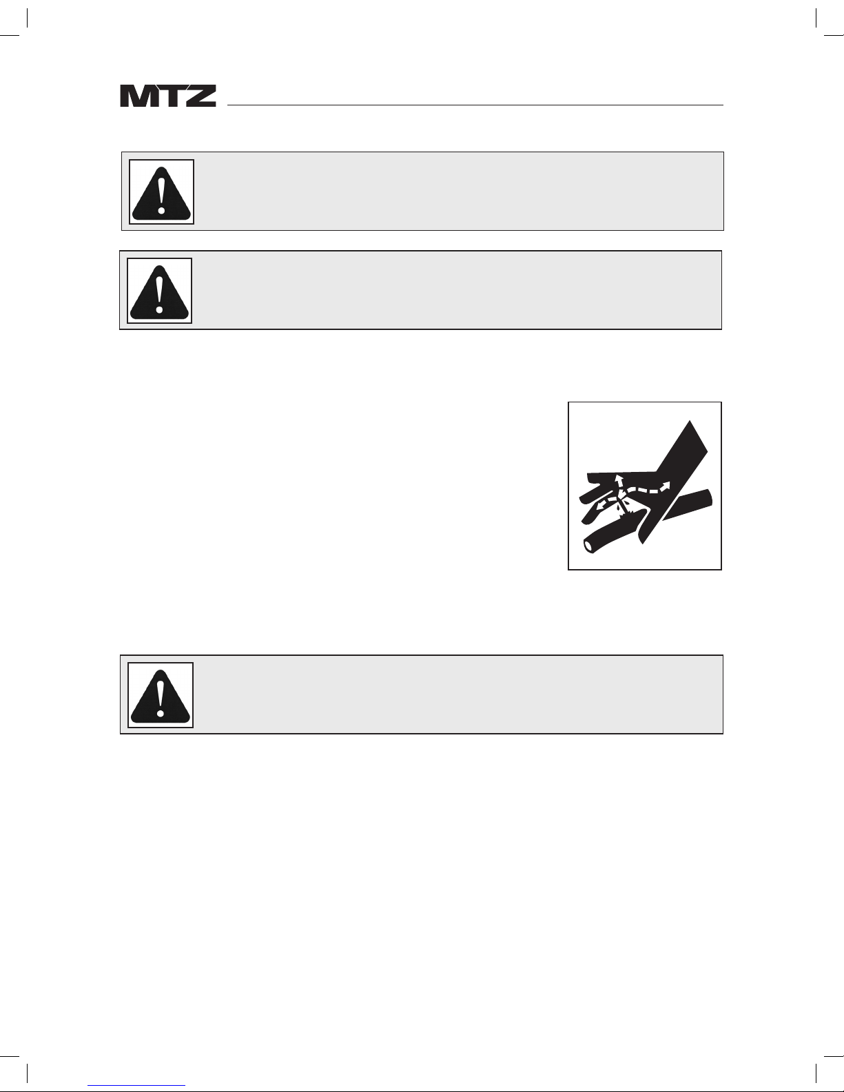
Hydraulic Safety
Escaping fluid under pressure can have sufficient force to penetrate
the skin, causing seroius personal injury. Before repairing, adjusting,
or disconnecting lines, be sure to relieve all pressure.
Before applying pressure to the system, be sure all connections are
tight and the lines, pipes and hoses are not damaged.
Wear proper hand and eye protection when searching for leaks. Use
a piece of wood or cardboard instead of hand to check for leaks.
Maintain all components in good working order.
If injured by escaping fluid, see a doctor at once. Serious infection
or toxic reaction can develop if proper medical treatment is not
administered immediately.
WARNING
Read the following safety information
WARNING
Tractor power steering must work normally when
operating the loader.
CAUTION
Only qualified personnel should perform these
procedures. Damage to the hydraulic system may
occur unless properly installed.
Page 4
4
Instructions
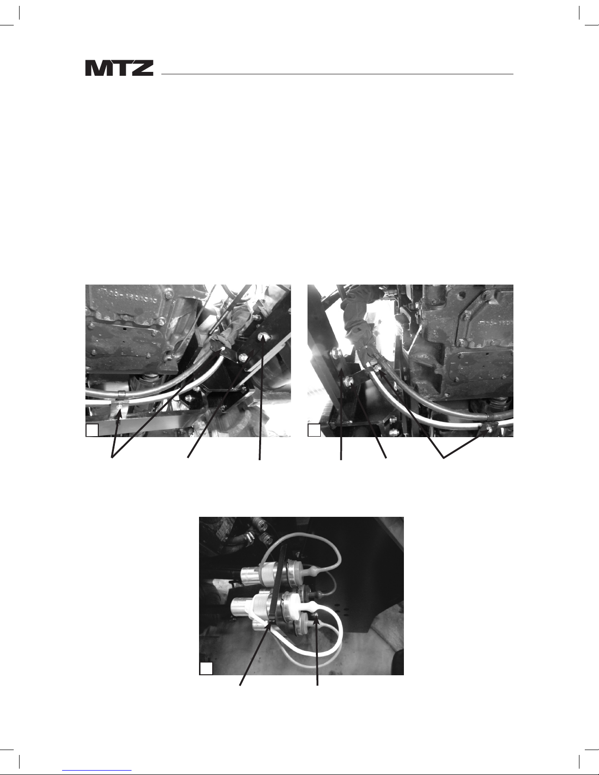
1. If the right and left hand brackets (13 & 14) weren’t placed on the axle mounts when the mount
kit was installed, do so now. See Graphics 1 & 2.
2. Assemble the bulkhead plate (1) to the plate on the RH mount as shown in Graphic 3, using the
M10 nuts and bolts provided (2 & 4).
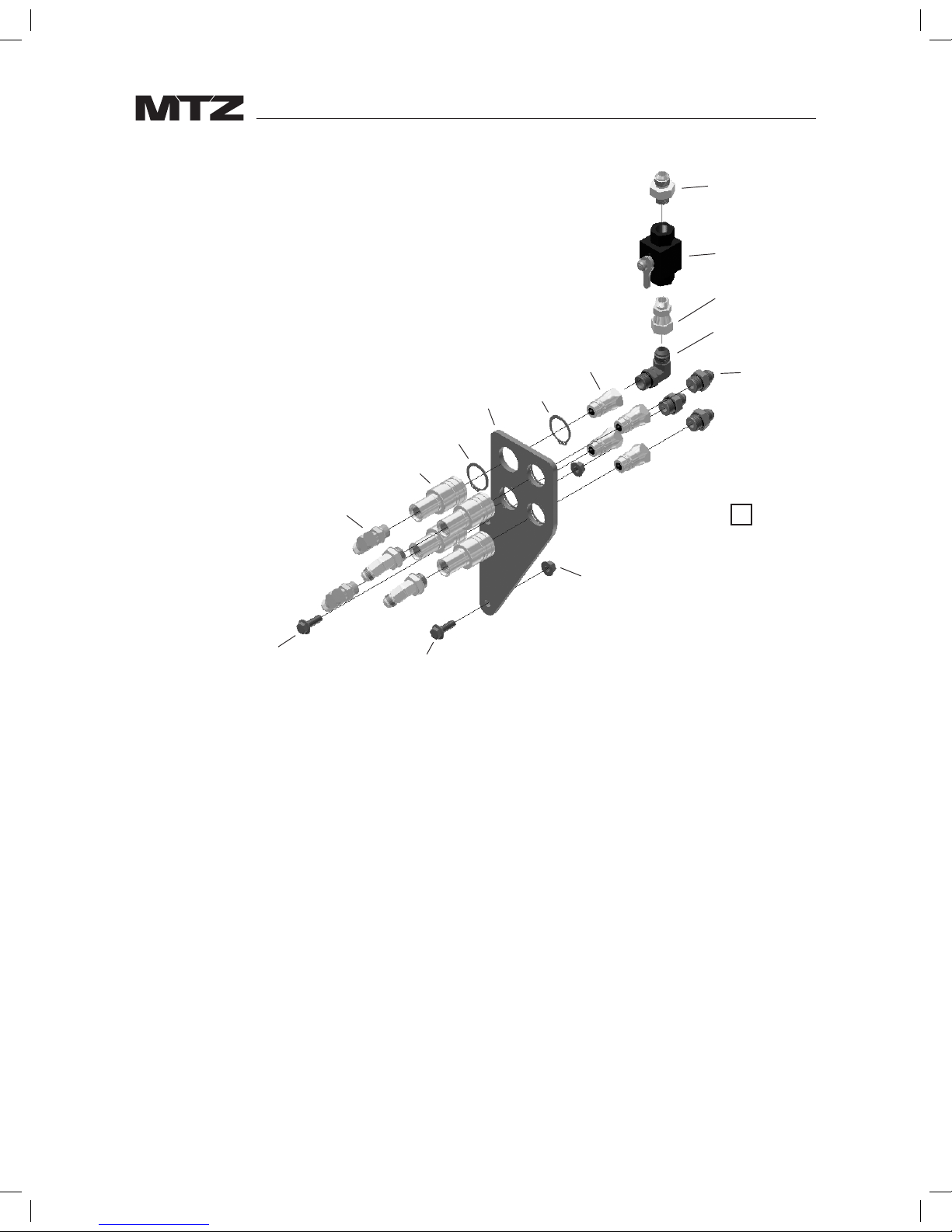
3. Place one snap ring (6) in the second slot on each of the four female quick couplers (10). Place
the quick couplers in the bulkhead facing forward. Place another snap ring on each of the four
quick couplers to secure them in the bulkhead. See Graphics 3 & 4.
4. Place one of the colored caps on each of the female quick couplers.
21
Harware
included in
mount kit
14 15, 16, 17
15, 16, 17 13
Harware
included in
mount kit
3
1 2, 4
Page 5
5
5. Place two 90° elbows (5) in the two inside quick connectors. For a 952, place two more 90°
elbows on the outside quick connectors also. For a 1220, place the two 45° elbows (20) on the
outside two quick couplers.
6. Starting at the right hand side of the tractor, feed the 80" hoses (12) down the inside of the
mount between the axle bar and tension rod, then cross under the tractor and up through the
left hand mount to the quick couplers under the step.
7. Place one piece of the 2.88" diameter nylon sleeves (25) over the two 80" hoses on the right
hand side. Then assemble both hoses to inner elbows of the bulkhead plate assembly.
8. Loosely assemble two P-clamps (15) on the hoses and bolt to the bracket on the right hand side
using the one of the bolts and nuts provided (16 &17). See Graphic 1. Repeat on the left hand
side. See Graphic 2.
9. Loosely assemble two P-clamps (15) on the bracket extending from the underslung using one
of the bolts and nuts provided (16 & 17). See Graphic 1
10. On the left hand end of each of the two 80" long hoses, place a 90° elbow (5) and then place a
male quick coupler (11) on the Morb end of the elbow. (Note that there are two styles of male
quick couplers in the hose kit. The Pioneer couplers (7) are used with the female quick couplers
on the bulkhead plate.)
11. Place the remaining 2.88" diameter nylon sleeve (25) over this end of the hoses. Then connect
the male quick couplers to the quick couplers underneath the step.
4
5
10
6
1
6
7
22
8
9
3
19
2
4
5 or 20
elbows
shown
Locking
Valve
4
NOTE:
952 placement is shown,
1220 placement is to the outside
Page 6

6
12. Check the hose routing to make sure it is clear of any sharp edges and the threaded tension
rods. If necessary, the P-clips on the two brackets can be moved to either hole or either side of
the bracket to get the required clearance. Tighten the hardware on the P-clips.
13. On each of the 24" hoses (18) place a 90° elbow (5) and then place a male quick connect coupler
(11) on the Morb end of the elbow. Connect the female JIC end of the hose to the remaining
fittings in the outside quick couplers in the bulkhead plate. Connect the male quick couplers to
right hand quick couplers under the cab.
14. Build the assembly of components around the locking valve as shown in Graphic 4. When
completed the assembly is placed in the top inside quick connector for 1220 (the top outside
for 952).
15. Place a straight male adaptor (19) on the remaining three male Pioneer quick couplers (7) and
connect to the end of the 90° end of the 51" hoses (21) on each of the couplers.
16. Place the 3.88" diameter nylon sleeve (26) over the MJIC end of hoses and slide to the 90°
fittings.
17. Slide the 43" hose (23) into the nylon sleeve making sure all the MJIC fittings are on the same
end.
18. Feed the hoses through the loop on the bottom of the liftarm and route to the tubelines on the
inside of the liftarm. (If the loader is not yet installed, do so now - consult loader manual for
further instruction.)
19. Connect the female JIC end of the 43" hose to the fitting on the top of ball valve and the MJIC
end of the hose to the lower of the four tubelines on the inside of the liftarms.
20. Connect the MJIC ends of the remaining hoses to the tubelines.. The hose that is connected
to the fitting below the ball valve should be connected to the tubeline that is second from the
bottom. The remaining two hoses get connected to the top two tubelines. Leave the quick
couplers unconnected at this time..
21. All the hoses are now in place. Adjust the fit of the hoses in nylon sleeves and secure the
sleeves with ty-wraps provided.
22. Connect the quick couplers at this time. On the 1220 the quick couplers for the lift cylinders
are on the left hand side. On the 952 they are on the right hand side. Move the quick couplers
(either at the bulkhead plate or at the tractor quick couplers) up or down to get the correct
loader operation.
23. Tighten any remaining hardware or connections once suitable routing for all hoses is found.
Loader is now ready for operation.
Page 7

7
X3944 Parts List
Item # Part Number Description Quantity
1 816603 Plate Bulkhead 1
2 00043435 Nut Hex Flg Usr M10 (Pl) 2
3 812734 Elbow 90 7/8 Mjic x 7/8 Orb 1
4 09840672 Bolt Hex Flg M10 x 30 8.8 (Pl) 2
5 811416 Elbow 90 7/8 Morb x 3/4 Mjic 8
6 812924 Snap Ring N1400 0150 86018680 8
7 813308 Male Tip Coupler 0.5 86025322 4
8 813852 Ball Valve 3/4 Forb 1
9 814660 Adaptor Str 3/4 Morb x 7/8 Swfjic 1
10 86033813 Coupler .5 Push Pull 7/8-14 Forb 4
11 813292 Quick Connect M Tip 4
12 816610 Hose 1/2 x 80" - 3/4 Swfjic x 3/4 Swfjic 2
13 816611 Bracket LH 1
14 816613 Bracket RH 1
15 815431 P Clamps 6
16 86170 Bolt 3
17 81344 Nut 3
18 816614 Hose 1/2 x 24 - 3/4 Swfjic x 3/4 Swfjic 2
19 886897 Adaptor Str 7/8 Morb x 3/4 Mjic S 5
20 816617 Elbow 45° 7/8 Morb 3/4 Mjic 2
21 816615 Hose 1/2 x 51.4" - 3/4 Swfjic-90 x 3/4 Mjic 3
22 812080 Adaptor Str 3/4 Morb x 3/4 Mjic 1
23 816616 Hose 1/2 x 42.86 - 3/4 Swfjic x 3/4 Mjic 1
24 812075 Ty-Rap 13-5/8" Lg (Ty-27m) 6
25 116298 Nylon Sleeve 36.00" 2.88 Dia 2
26 117922 Nylon Sleeve 36.00" 3.66 Dia 1
27 813295 Dust Plug 0.5 Blue 1
28 813296 Dust Plug 0.5 Yellow 1
29 813297 Dust Plug 0.5 Red 1
30 813298 Dust Plug 0.5 Green 1
31 813301 Dust Cap 0.5 Blue 1
32 813302 Dust Cap 0.5 Yellow 1
33 813303 Dust Cap 0.5 Red 1
34 813304 Dust Cap 0.5 Green 1
35 813305 Dust Cap 0.5 Black 2
36 813306 Dust Cap 0.5 Orange 2
Page 8

8
Standard
Bolt Size
(in)
Grade 2 Grade 5 Grade 8
Torque Torque Torque
ft-lb NM ft-lb NM ft-lb NM
0.25
0.313
0.375
6
11
20
7
15
27
8
17
31
11
23
41
12
25
44
16
33
60
0.438
0.5
0.563
32
49
70
43
66
95
49
76
109
66
103
148
70
106
153
95
144
207
0.625
0.75
0.875
97
144
166
131
195
225
150
266
430
203
360
583
212
376
606
287
509
821
1
1.125
1.25
250
354
500
339
480
678
644
795
1120
873
1077
1518
909
1288
1817
1232
1745
2462
1.375
1.5
655
870
887
1179
1470
1950
1992
2642
2382
3161
3228
4283
Metric
Bolt Size
(mm)
Class 5.6 Grade 8.8 Grade 10.9 Grade 12.9
Torque Torque Torque Torque
ft-lb NM ft-lb NM ft-lb NM ft-lb NM
6
8
10
3.1
7.7
15
4.3
10.5
21
7.3
17.7
35
9.9
24
48
10.3
25
49
14
34
67
12.1
29
59
16.5
40
81
12
14
16
26
42
64
36
58
88
61
97
147
83
132
200
86.2
136
210
117
185
285
103
162
250
140
220
340
18
20
22
89
126
169
121
171
230
202
287
390
275
390
530
287
405
549
390
550
745
346
486
656
470
660
890
24
27
30
217
320
435
295
435
590
497
733
995
675
995
1350
708
1032
1401
960
1400
1900
840
1239
1681
1140
1680
2280
33
36
39
590
759
988
800
1030
1340
1349
1740
2249
1830
2360
3050
1902
2441
3163
2580
3310
4290
2278
2935
3798
3090
3980
5150
Dash
Size
Thread
Size
Jam Nut or Straight SAE 37° (JIC)
ORB Fitting Torque Swivel Nut Torque
ft-lb NM ft-lb NM
-04
-05
-06
7/16-20
1/2-20
9/16-18
14-16
18-20
24-26
20-22
24-27
33-35
10-11
13-15
17-19
13-15
18-20
23-26
-08
-10
-12
3/4-16
7/8-14
1-1/16-12
50-60
72-80
125-135
68-78
98-110
170-183
34-38
50-56
70-78
47-52
69-76
96-106
-14
-16
-20
1-3/16-12
1-5/16-12
1-5/8-12
160-180
200-220
210-280
215-245
270-300
285-380
80-90
94-104
124-138
110-122
127-141
169-188
-24 1-7/8-12 270-360 370-490 156-173 212-235
Bolt Torque Chart
Page 9

Page 10

36 Renaissance Crt.
Thornhill, Ontario,
Canada, L4J 7W4
Ph.: 1.855.246.4689 | Fax: 1.647.933.9066
www.mtzequipment.com
Equipment shown is subject to change without notice.
©2013 MTZ Equipment Ltd.
3-1136 Centre St., Ste. 124,
Thornhill, Ontario
L4J 3M8 Canada
Tel: 1-855-246-4689 | Fax: 1-647-933-9066
www.mtzequipment.com
 Loading...