

Page 1

1
MTZ
TRACTORS
900/900.3
920/920.2/920.3
950/950.3
952/952.2/952.3
900 – 0000010 OM
OPERATING MANUAL
2009
Page 2

2
IMPORTANT!
If the tractor is operated by the user or lent/leased, make sure that the operator prior to
working on the tractor:
A. has been instructed on safety measures and proper tractor use;
B. has studied and understood the content of this Operating Manual.
NOTE!
Due to continual improvement of the products manufactured, some modifications not
reflected herein may be made to the design of some subassemblies and parts.
Some technical data and illustrations given herein may differ from the actual ones for
your tractor. The dimensions and weights are approximate (reference). For the detailed
information, contact the MTZ trademark dealer.
General note: The references to the “left” and “right” in the text of this Manual are given
from the standpoint of the observer staying behind the tractor moving ahead.
© Minsk Tractor Works Republican Unitary Enterprise, 2009
Page 3

3
Table of Contents
Introduction
6
Adopted Abbreviations and Symbolic Notations
8
International Symbols
9
Safety Precautions
11
Technical Data
15
Controls and Instruments
32
Operating Instructions
81
Unitization
127
Adjustments
155
Maintenance
170
Troubleshooting
219
Tractor Transportation and Towing
227
Tractor Storage
228
Appendix А. Electric Equipment
229
Page 4

4
All rights reserved. This book shall not be reproduced or copied either fully or
partially without written permission of the Minsk Tractor Works Republican
Unitary Enterprise.
ATTENTION OF THE TRACTOR OPERATORS!
1. Prior to operating the tractor, read carefully this User Manual and follow strictly its
requirements.
2. Apply the climatic diesel fuel according to the Manual. Reduce the motor oil
changeover intervals by half, if the sulphur content in the fuel is below 1%.
3. Do not allow the diesel engine idling for more than 15 minutes.
4. Please keep in mind that the engine can be only started when the gearbox lever is
set to the leftmost position (to the position of engagement of the 1st or 2nd range of
gears).
5. When operating the tractor without the rear PTO, put the switchover shifter arm of
the independent two-speed PTO drive to position I (540 rpm), the independent
synchronous PTO drive – to the neutral (middle) position and the control lever – to
the position “PTO OFF” (refer to Section “Operating controls and Instrumentation”).
6. Use the synchronous PTO drive at the tractor unit movement speeds not exceeding
8 km/h. Otherwise, severe damages of the tractor transmission can be caused.
7. The tractor should be only operated at the 9th gear with the higher gear range (range
II) engaged.
8. The tractor cab is equipped with a single seat and only the operator must be in.
9. When shipping the tractor from the factory, some tractor components are packed in
the box of spare parts and accessories, toolbox or cab. Fit them onto the tractor by
your own.
10. When putting new storage batteries into operation, remove the airtight film from the
air holes or cut the lugs on PE plugs off.
11. Do not allow tractor operation with the clutch disengaged or incompletely engaged.
12. When starting the movement, make sure that the manual reserve parking brake is
off.
Page 5

5
13. When using the tractor without drive shafts, put FDA lever to position “forced”.
14. Do not operate the tractor indoors without adequate ventilation (air exchange).
Exhaust gases can lead to fatal outcome.
15. Towing the tractor with front wheels lifted is strictly forbidden. Otherwise, the FDA
drive failure and emergency situation can occur.
16. Never lift the tractor by the front part of the tractor by the towing shackle. Use the
shackle for towing only.
17. The manufacturer is improving continually the tractor due to that there could be
some modifications of the design of some components and their operating rules is
not reflected in this Manual.
Page 6

6
INTRODUCTION
The MTZ wheeled universal tilling tractors of the 900 series belong to drawbar category
1.4 and are designed to perform a wide range of agricultural works: from soil
preparation for sowing to harvesting and transporting operations; they can be used in
forestry, municipal servicing, construction and industry.
This Manual contains the description of the design peculiarities, brief technical data and
recommendations for operation and maintenance of the following MTZ tractors of 900
series:
MTZ- 900 (4х2) with the Д-243/Д-243C diesel engine (59.6 kW/2200 rpm) and
synchronized gearbox;
MTZ-900.3 (4х2) with the Д-245.43 S2 diesel engine (62 kW/1800 rpm), synchronized
gearbox and updated design;
MTZ-920 (4х4) with the Д-243/Д-243C diesel engine (59.6 kW/2200 rpm), synchronized
gearbox and FDA (72);
MTZ-920.2 (4х4) with the Д-243/Д-243C diesel engine (59.6 kW/2200 rpm),
synchronized gearbox, FDA (822) and updated design;
MTZ-920.3 (4х4) with the Д-245.43 S2 diesel engine (62 kW/1800 rpm), synchronized
gearbox, FDA (822) and updated design;
MTZ-950 (4х2) with the Д-245.5/Д-245.5C diesel engine (65 kW/1800 rpm),
synchronized gearbox;
MTZ-950.3 (4х2) with the Д-245.5 S2 diesel engine (65 kW/1800 rpm), synchronized
gearbox and updated design;
MTZ-952 (4х4) with the Д-245.5/Д-245.5C diesel engine (65 kW/1800 rpm),
synchronized gearbox and FDA (72);
MTZ-952.2 (4х4) with the Д-245.5/Д-245.5C diesel engine (65 kW/1800 rpm),
synchronized gearbox, FDA (822) and updated design;
MTZ-952.3 (4х4) with the Д-245.5 S2 (70 kW/1800 rpm) diesel engine, synchronized
gearbox, FDA (822) and updated design.
Index ―.2‖ means upgrading of the respective model by installing one or several units of
higher engineering level:
FDA with planetary reducing gears (for 4x4 tractors);
Hydraulic lift-based hookup;
Bonnet, roof, cab fender of updated design.
Index ―.3‖ means installation of diesel engines with index S2 certified as per the 2nd
stage of the ecological regulation of Directive 2000/25/EC, hydrostatic power steering
(HPS) system with an independent oil tank, as well as the bonnet, the roof and cab
fenders of renewed design.
Making any re-equipment or modifications to the tractor design, which are not
authorized by the Manufacturer is strictly forbidden.
Page 7

7
The distinctive features of the tractors described in the Manual:
1. Transmission with synchronized gearbox (7/2) and synchronized reducing gear (step-
up gear): 14 forward and 4 reverse gears.
2. Hydrostatic power steering with the Danfoss metering pump, cylinder in steering
trapezium and steering tie rod.
3. Unified rear driving axle with more convenient external readjustment of planetary
gear brake bands.
4. Hydraulic system with a power regulator completely controlling the rear attachment
cylinder. Three sections of the distributor ensure the control of external cylinders of
machines and tools.
5. Safe comfortable cab meets the requirements of EC and OECD directives and is
featured by the improved interior, heating and ventilation system.
Page 8

8
Adopted Abbreviations and Symbolic Notations
SB
—
storage battery
DL
—
differential lock
PCU
—
pre-heater control unit
SCU
—
starter control unit
UDP
—
diesel piston upper dead point
PTO
—
power take-off shaft
HMS
—
hydraulic mounted system
HPS
—
hydrostatic power steering
LOHE
—
liquid oil heat exchanger
RMA
—
rear mounted attachment
ID — integrated display
GB
—
gearbox
C — clutch
CAC
—
charge air cooler
FDA
—
front driving axle
ADCS
—
automatic tilling depth control system
M — maintenance
DHM
—
traction hitch mechanism
SRU
—
speed reducer
ETPP
—
electric torch pre-heater
ОЕСD
—
Organization for Economic Cooperation and Development
Page 9

9
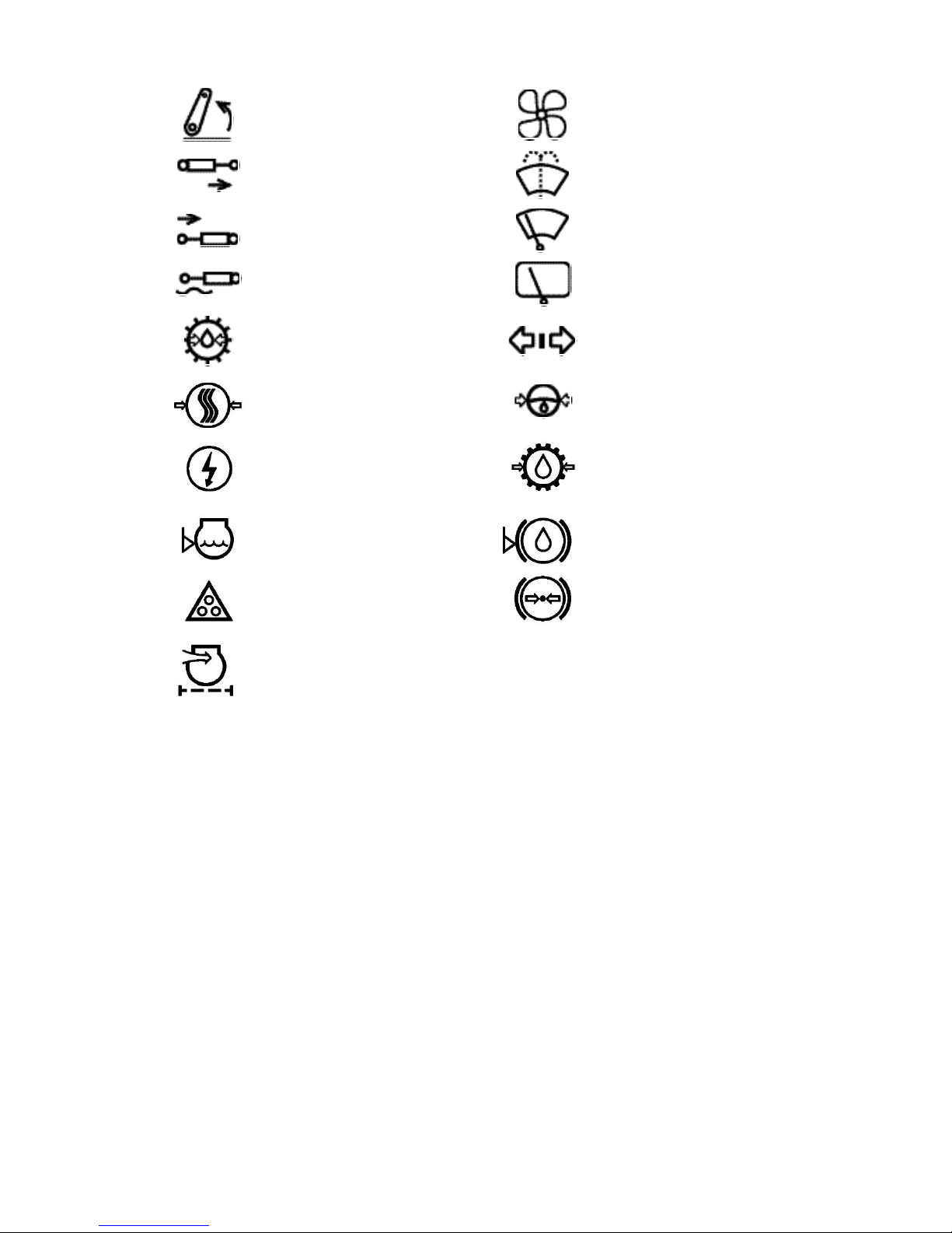
International Symbols
Manufacture uses standard international symbols concerning the application of devices
and the controls.
Below are given the symbols with their meaning.
— See Manual
— Control manipulations
— Brake
— Fast
— Parking brake
— Slow
— Horn
— Forward
— Emergency alarm
— Reverse
— Fuel level in the tank
— Battery charging
— Cooling fluid
— Cab light
— Starting flame preheater
— Clearance lights
— Engine speed
— Turn indicator
— Oil pressure in the engine
— Upper beam
— Engine cooling fluid
temperature
— Lower beam
— Off/Stopped
— Working lights
— On/Start
— Differential locking
— Ramping
— PTO engaged
— Lever – down
— FDA engaged
Page 10
10
— Lever – up
— Fan
— Lifting position of the
distributor sliding valve
— Windscreen washer
— Lowering position of the
distributor sliding valve
— Windscreen wiper
— Floating position of the
distributor sliding valve
— Rear screen wiper
— Oil pressure in the gearbox
— Trailer turn indicator
— Air pressure in the
pneumatic system
— Oil pressure in the
hydrostatic power steering
— High voltage
— Oil pressure in the
transmission
— Cooling fluid level
— Brake fluid level
— Road train lights
— Air pressure in the brake
system
— Air filter clogging
Page 11

Safety Precautions
MTZ series 900
11
SAFETY PRECAUTIONS
Strict observance of safety precautions, accurate execution of tractor
driving and operation regulations
and maintenance shall guarantee
complete safety of its application.
Safety precautions when operating the tractor
ATTENTION! When starting up the en-
gine and operating the controls, always
stay in the cab on the operator’s seat
л
General Instructions
•
• Prior to tractor use, study operator’s
manual carefully. Insufficient
knowledge on tractor driving and operation can result in accidents.
• Specially trained and qualified
operators only are allowed to operate the tractor.
• If the tractor is equipped with a
safety belt, use it during operation. If
not, contact the dealer.
• Never admit a passenger to the cab
unless the latter is provided with an ad d i t i o n a l s e a t a n d h a n d -rail. There is no
other safe seat for a passenger in the
c a b !
• Keep all warning plates clean. In case of
their damage or loss, replace them by
new ones.
• Prior to operation, carefully inspect the tractor and a trailed
mechanism. Start operation having
made sure that they are in good repair. The trailed agricultural mechanisms and transport trailers shall
be fitted with rigid hitches excluding
their swinging and rear-end collision with the tractor during transportation.
• Prior to starting the diesel engine,
the parking brake shall be applied;
the gear shift lever shall be set to
the neutral position and the PTO
lever – in the OFF position.
• Prior to starting the movement,
warn the bystanders and the persons working on the trailed mechanisms with a horn.
• Never leave the moving tractor.
• Prior to leaving the cab, disen-
gage the PTO, stop the engine, apply the parking brake, take off the
starter switch key and set the battery disconnect switch to the OFF
position.
It is forbidden to de-energize the
electric equipment system by the
starter and instrumentation switch
and/or battery disconnect switch
until the engine is stopped.
• Do not operate the tractor indoors
without necessary ventilation. Exhaust gases can result in fatal outcome!
• In case of failure of the engine or
steering control, stop the tractor
immediately. Keep in mind that
turning the steering wheel for controlling the tractor when the engine
is stopped requires much more
force. In case of failure of the steering control, a lamp of emergency oil
pressure in the HVSS lights up.
• Do not work under lifted agricultural implements. During durable
stops, leave the attached implement lifted.
• If the front part of the tractor takes
off when attaching heavy mechanisms and implements, mount front
weights.
• When operating the front lift, fill in
the rear tires with liquid ballast.
• Prior to lifting and lowering the attached agricultural implements as
well as when turning the tractor,
make sure that there is no risk of
hitting or snagging on somebody or
Page 12

Safety Precautions
MTZ series 900
12
any obstacle.
• When moving with attached
mechanisms or implements, always
apply a mechanism to lock on the
attachment in lifted position.
• The drive shaft transferring the rotation from the tractor PTO to the
driven components shall be enclosed.
• Make sure that any additional
equipment or auxiliaries are installed correctly and that they are
designed for application with your
tractor. Keep in mind that your tractor, if used unduly can be dangerous both for yourself and other persons. Do not operate equipment
not designed for installation on the
tractor.
• To avoid turnover, be careful
when driving the tractor. Choose
safe speed corresponding to road
conditions, particularly when driving
cross-country, passing the ditches,
slopes and during sharp turns.
• When operating on the slopes, increase the tractor track to the maximum value.
• Do not make sharp turns under
full load and high speed.
• When using the tractor for transportation works:
- increase the tractor track to at
least 1800 mm;
- interlock the brake pedals, check
and, if necessary, adjust the brakes
to synchronous action;
- check operation of the parking
brake, brake pneumatic drive and
trailer brakes;
- check the state of the light and
audio alarm devices;
- transport trailers shall be fitted
with rigid hitches and connected by
means of the safety chain or rope;
- never drive downhill with
switched-off gear (coasting), apply
the same gear both down and uphill;
- it is forbidden to work with the
trailer without independent brakes,
if its weight exceed half actual
weight of the tractor. The faster you
move and the larger the towed
mass is, the larger the safety distance shall be;
- disengage the FDA to avoid excessive wear and tear of the drive
parts and tires;
- do not use rear axle differential
lock (DL) at the speed of above 10
km/h and during turns;
Important! Use the synchronous
PTO drive at the lower gears of the
gearbox at the tractor movement
speed not exceeding 8 km/h. Otherwise, the tractor’s power train can be
severely damaged.
- do not stop the tractor on the
slopes. If the stop is still necessary,
engage the 1st gear and apply the
parking brake.
• when operating the equipment
driven by PTO, make sure that the
PTO coupler shank has fully
stopped after stopping the engine
before leaving the cab and disconnecting the equipment.
• Do not wear loose clothes when
operating PTO or near the rotating
equipment.
• When operating stationary mechanisms driven by PTO, always apply the parking brake and lock on
the rear wheels from the front and
behind. Make sure that the mechanism has been reliably secured.
• Make sure that the PTO coupler
shank protection has been installed
and, if the PTO is not used, refit the
cap of the PTO coupler shank.
Page 13

Safety Precautions
MTZ series 900
13
• Do not clean, adjust or maintain
the equipment driven with PTO,
when the engine is running.
Safety precautions during the
maintenance
• Never refuel the tractor when the
engine is running.
• Never smoke when refuelling.
• Never fill the tank to the top.
Leave some space for fuel expansion.
• Never add gasoline or mixtures to
diesel fuel. These combinations
can increase the risk of fire or explosion.
• Use the summer or winter fuel
grades properly. Refill the tank at
the end of each day to reduce night
moisture condensation.
• To avoid fuel spillage during the
mechanized refuelling of the tractor, remove the mesh filter from the
fuel tank neck. The mesh filter is
designed for tractor manual refuelling under field conditions.
• Fill in the tractor with oils and lubricants recommended by the manufacturer. Application of other lubricating materials is strictly forbid-
den!
• Any operations related to cleaning
the engine and tractor, preoperation, maintenance, etc. should
be performed with the engine
stopped and tractor braked.
• Cooling system operates under
pressure, which is maintained by a
valve installed in the cap of the filler neck. It is dangerous to re-
move the lid on the hot diesel
engine. To avoid burns of hands
and face, unplug the radiator neck
cap on the hot engine carefully,
having put a thick cloth on the cap
and a gauntlet on the hand.
• To avoid burns, be careful when
draining the cooling fluid or water
from the cooling system and/or hot
oil from the engine, hydraulic system and transmission.
• When servicing the storage batteries, be careful because the contact of electrolyte with the skin
causes burns.
• To avoid the risk of explosion,
keep any sources of open flame
away from the engine fuel system
and storage batteries.
• Keep the tractor and its equipment, particularly the brakes and
steering, in serviceable condition to
ensure your and bystanders’ safety.
• Do not make any modifications to
the tractor or any parts thereof
without approval of your dealer and
manufacturer.
Safety requirements during operation and maintenance of electrical equipment
• To avoid damage of semiconductor devices and resistors, observe
the following precautions:
- do not disconnect the storage battery (SB) terminals with the engine
running. This will cause peak voltage to appear in the discharge circuit and lead to unavoidable failure
of diodes and transistors;
- do not disconnect electric cables
until the engine is shut down and
all switches are off;
- do not allow a short circuit to occur due to incorrect wire connection. Short circuit or wrong polarity
will cause failure of diodes and
transistors;
- do not connect the SB to electrical
equipment system until the polarity
Page 14

Safety Precautions
MTZ series 900
14
of outputs and voltage is verified;
- do not check the presence of
electric current by producing a
spark, since this would lead to immediate breakdown of the transistors.
Hygienic requirements
• Fill in a vacuum flask with fresh
portable water daily.
• Firs-air kit shall be necessarily
stuffed with bandages, tincture of
iodine, ammonia spirit, borated petrolatum, soda, validol and dipyrone.
• Depending on the operating conditions, use the natural ventilation
of the cab or the latter’s heating
and cooling unit.
• Should the durations of the continuous work on the tractor exceed
2.5 hours within a working shift, the
noise protection facilities to State
Standard ГОСТ 12.4.051-87 (ear-
plugs, antiphones) shall be used.
Fire safety requirements
• The tractor shall be provided with
fire-fighting equipment, i.e. a spade
and fire extinguisher. It is forbidden
to operate the tractor without fireextinguishing equipment.
• The places for parking the tractor
and storing the combustive and lubricating materials shall be tilled
with a strip of min 3 m wide and
provided with fire-extinguishing
equipment.
• Do not allow manifold and silencer soiling with dust, fuel, straw, etc.
• Do not allow straw to wind around
rotating parts of mechanisms unitized with the tractor.
• When washing the parts and assembly units in kerosene or gaso-
line, take measures excluding ignition of flushing liquid vapours.
• Do not operate the tractor in firerisky place with the bonnet and
other protective facilities removed
from the heated engine parts.
• Do not allow using open flame to
heat oil in engine pan or burn out
soiling of radiator core.
• If a seat of fire occurs, strew sand
over it and cover it with tarpaulin,
sack cloth or other thick fabric. Use
a carbon dioxide fire extinguisher.
Do not extinguish burning fuel with
water.
• Watch that there are no highly inflammable materials near the manifold and the silencer when the engine is running.
• When harvesting hay, straw,
working in places of higher fire risk,
apply spark suppressors in the exhaust system as an assembly with
the silencer or independently.
Page 15
Specifications
MTZ series 900
15
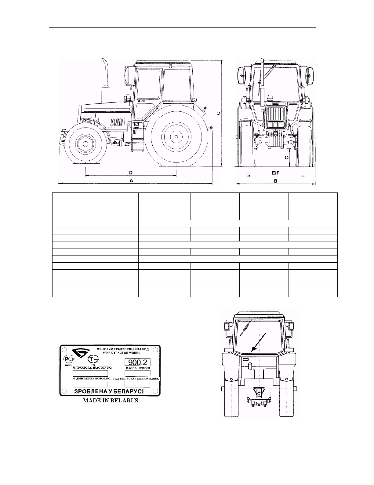
SPECIFICATIONS
Parameter
9 0 0 / 900.3
920/920.2/920.3
950/950.3
95 2/952.2/952.3
А Length, mm: total
without weights
to wheels
4120/4440
3840/4440
3700
4120/4130/4440
3970/4000/4060
3840/3850/3850
4120/4440
3840/4060
3700
4120/4130/4400
3970/4000/4060
3840/3850/3850
В Width, mm
1970
С Height to cab top, mm
2820
2850
2820
2850
D Longitudinal base, mm
2370±20
2450±20
2370±20
2450±20
Е Rear wheel track, mm
1500-1600/1800-2100
F Front wheel track, mm
1450-1850
1410-1990/1420-1970
1450-1850
1410-1970/1420-1970
G Clearance, mm
465
Tire size: front wheels
9,00-20;9,00R20
13,6-20;360/70R24
9,00-20;9,00R20
13,6-20;360/70R24
rear wheels
18,4R34 (Ф-11)
16,9R38;
18,4R34 (Ф-11)
18,4R34 (Ф-11)
16,9R38;
18,4R34
Service weight
(without ballast), kg
3850/3950
4100/4200/4300
3850/3950
4100/4200/4300
Numbers of tractor component parts
Name plate of the tractor containing the
serial numbers of the tractor and engine.
Page 16
Specifications
MTZ series 900
16
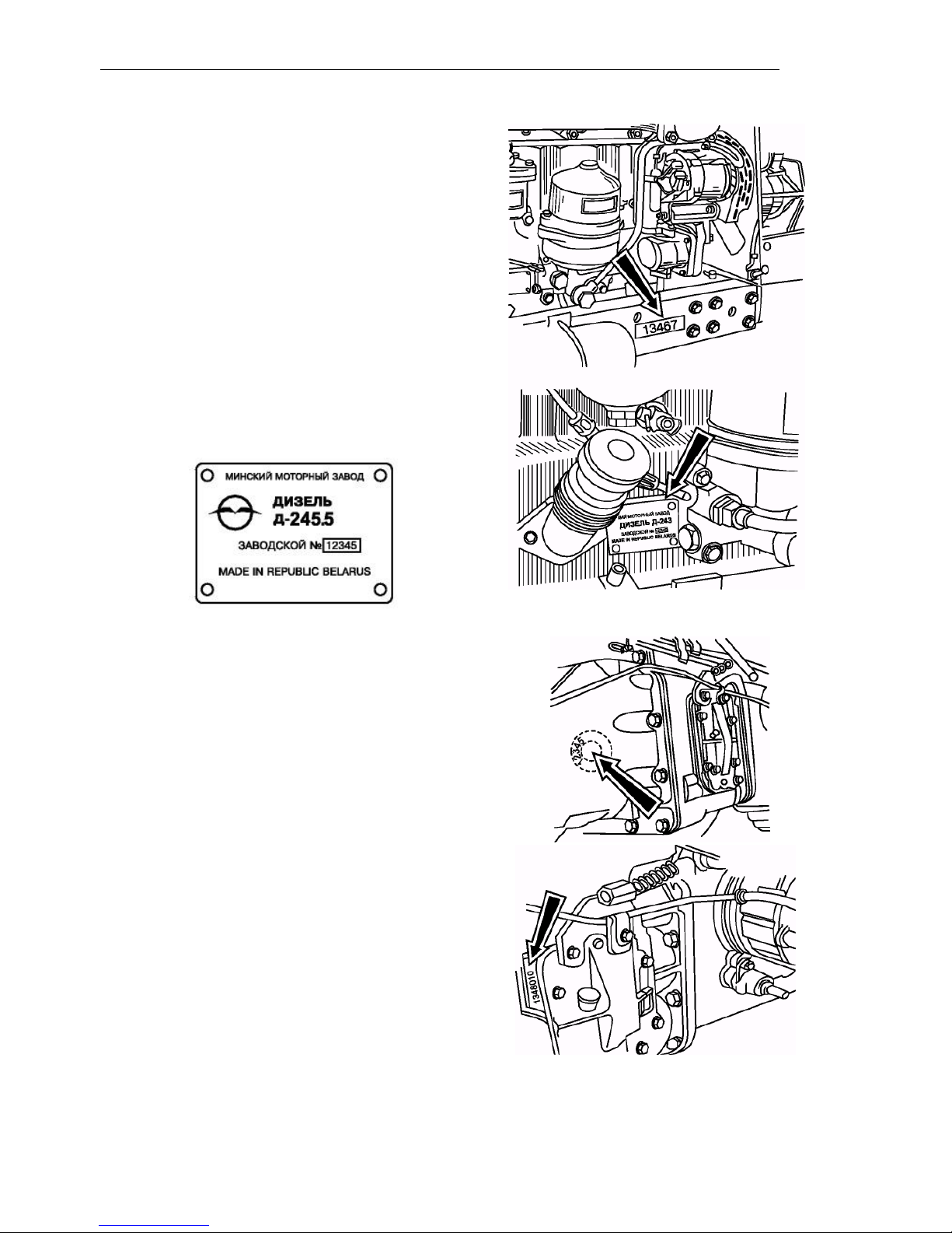
The serial number of the tractor is replic a ted on the front end of the right-h a n d side
member of the half-frame (on the right
plate of front balance weights) .
Engine number (is duplicated on engine
name plate attached on the right of the
cylinder block) .
Clutch number (on the left of the clutch
housing).
Gearbox number (on the left of the
gearbox housing)
Page 17
Specifications
MTZ series 900
17
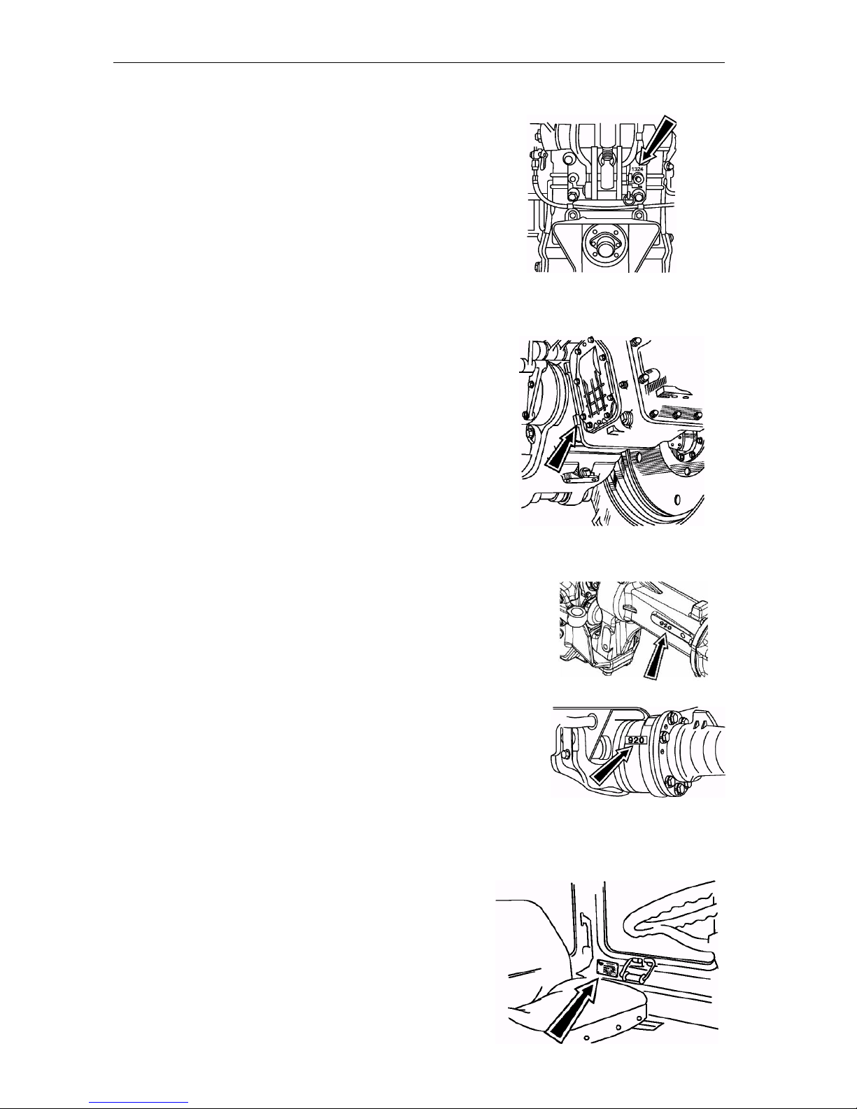
Transmission number (on the rear axle
housing from behind).
Transmission number for the tractor with
hydraulic lift (on the rear axle housing at
the joint with the gearbox on the right).
FDA number (on the right -hand sleeve at the
front of the FDA (822) o r on the central housing
at the front of the FDA (72)) .
Cab serial number and OECD certificate num ber (inside the cab on the left).
Page 18

Specifications
MTZ series 900
18
Engine
Engine make
Д-243/243C
Д-245.5/Д-245.5C
Д-245.43 S2
Д-245.5 S2
Type
Four-stroke, inline, naturally aspirated
Four-stroke, inline, turbocharged
Four-stroke, inline, turbocharged, with intermediate charge
air cooling
Four-stroke, inline, turbocharged, with intermediate charge
air cooling
Number of cylinders
4
Method of mixing
Direct injection
Compression (calculated)
16
15.1
15.1
15.1
Bore, mm
110
Stroke, mm
125
Displacement, l
4.75
Order
1-3-4-2
Cooling system
Liquid
Rated speed, rpm
2200
1800
1800
1800
Max speed, rpm
2380
1980
2050
2070
Min speed, rpm
600
700
800
800
Rated power, kW (H.P.)
60 (81)
at 2200 rpm
65 (89)
at 1800 rpm
62 (83.7)
at 1800 rpm
70 (94.5)
at 1800 rpm
Max torque N·m
296.9 at 1400 rpm
386
at 1400 rpm
411
at 1400 rpm
464
at 1400 rpm
Clearance between intake
and exhaust valves and
rockers at idle running,
mm
0.25…0.30
0.25…0.30 – for
intake valves,
0.40…0.45 – for
exhaust valves
0.20…0.30 – for
intake valves,
0.35…0.50 – for
exhaust valves
0.20…0.30 – for
intake valves,
0.35…0.50 – for
exhaust valves
Advance angle of fuel injection before upper dead
point (UDP), degrees
20±1/16±1
18±1/13±1
or 9±1
4.0±0.5
4.0±0.5
Fuel injection pressure,
MPa
21.6…22.4
21.6…22.4
23.5…24.7
23.5…24.7
Page 19

Specifications
MTZ series 900
19
Diesel engine lubrication system
Type: combined, with oil radiator (or
LOHE for tractors
900.3/920.3/950.3/952.3).
Min oil pressure:
0.08 MPa (0.8 kgf/cm2) at 600 rpm.
Normal oil pressure:
0.2…0.3 MPa (2…3 kgf/cm2).
Max pressure at cold diesel engine: up
to 0.6 MPa (6 kgf/cm2).
Lubrication system capacity: 12 l.
Motor oil brands:
- from -40°С to +5°С: М-8ДМ; М-8Г2,
М-8Г2К or М4
3
/8Г
2
(SAE-20,
SAE 10W-20);
- from +5°С to +50°С: М-10ДМ; М-10Г2;
М-10Г2К (SAE-30);
- multigrade oil: SAE 15W-40.
Engine feed system
Fuel pump: 4-plunger pump, in-line, with
boost pump.
Governor: mechanical, variable-speed
(with antismoke pneumatic equalizer – for
diesel engines Д-245.5/Д-245.5C/
Д-245.5 S2/Д-245.43 S2).
Turbocharger: centripetal radial turbine
on a shaft with centrifugal compressor (Д-
245.5/ Д-245.5C/Д-245.5 S2/Д-245.43
S2).
Charge air cooler (for Д-245.5S2/Д-
245.43S2): air-air type, mounted prior to
water radiator.
Fuel filters: coarse filter and secondary filter (with removable paper filter element).
Fuel brand: Diesel: summer
Л-0.2-40, Л-0.5-40; winter З-0.2, З-0.5; at 50°С – А-0.2, А-0.4.
Fuel tank capacity: 130 l
(2 tanks); 120 l (one tank) for tractors with
hydraulic lift.
Air cleaner: combined, with centrifugal
and oil-bath air cleaning.
Air cleaner oil bath capacity: 1.5 l (3.0 l
– for the Д-245.5 engine).
Donaldson dry-type air cleaner – for Д-
245.5 S2/ Д-245.43 S2.
Engine starting system
Electric starter type, 12 V or 24 V.
Easy starting facilities:
- electric torch pre-heater (filament plug in
the intake manifold) or filament plugs in
diesel cylinder head (for the engines with
the index ―S2‖).
Engine cooling system
Type: water, closed with forced liquid cir-
culation, temperature controlled by the
thermostatic regulator and a shutter from
the driver’s seat, with expansion tank (for
Д-245.5 S2/Д-245.43 S2).
Normal operating temperature: from 80°С
to 100°С.
Cooling system capacity: 20 l.
Steering control
Type: Hydrostatic power steering with
steering cylinder in the steering linkage.
Independent oil tank of HPS (for MTZ -
900.3/920.3/950.3/952.3).
Safety valve adjustment pressure – 14
MPa.
Shock valve adjustment pressure – 20
MPa.
Oil brands:
BECHEM Stariol №32;
ADDINAL Hydraulikol HLP 32;
THK Hydraulic HLP 32.
Feed pump capacity: 21 l/min (28 l/min)*
Hydraulic cylinder: two-way type,
• bore: 50 mm (63 mm)*
• stroke: 200 mm.
Metering pump: volumetric constant: 100
cm3/rev (160 cm3/rev)*, operating pressure: from 10 to 14 MPa. Installed at the
front wall of the cab.
Steering wheel position control limits:
• by inclination: from 25° to 40° with fixation through 5°;
• by height: – within the range of 100 mm.
Steering wheel free play: not more
*
For the FDA with planetary-cylindrical reducing
gears (MTZ-920.2/920.3/952.2/952.3)
Page 20
Specifications
MTZ series 900
20
than 25°.
Clutch
Type: friction, dry, single-disk, with tangential suspension of the pressure plate.
Driven disk diameter – 3 40 mm.
Gearbox
Type: 7/2, mechanical, stepwise, syn-
chronized, dual-range.
I range (stage): 1
s t
, 2
n d
and 3
r d
gear of for -
ward motion and one gear of reverse.
I I range (stage): 1
s t
, 2
n d
, 3
r d
and 4
t h
gears
of forward motion and one of reverse.
ATTENTION! The 4
t h
gear can be only
e n g a g e d i f t h e I I range is selected.
Calculated speeds (km/h) of MTZ 900 series tractors:
Rated engine rotational speed, rpm: 2 2 0 0
Rear tyres: 18.4R34
Synchronized splitter
Motion
Gear
number
Gear
number
V tr,
km/h
front
1
I
2.5
3.2 2 7.1
9.4 3 8.4
11.1
1
II
4.2
5.5 2 12.1
16.0
3
14.3
18.9
4
26.6
35.2
rear
1R
5.2
6.8
2R
II
8.8
11.6
Rated engine rotational speed, rpm: 2 2 0 0
Rear tyres: 16.9R38
Synchronized splitter
Motion
Gear
number
Range
number
V tr,
km/h
front
1
I
2.5
3.4 2 7.4
9.8 3 8.7
11.6
1
II
4.3
5.7
2
12.6
16.6
3
14.9
19.7
4
27.7
36.6
rear
1R
I
5.4
7.1
2R
II
9.1
12.1
Page 21
Specifications
MTZ series 900
21
Rated engine rotational speed, rpm: 1 8 0 0
Rear tyres: 16.9R38
Synchronized multiplier
Motion
Gear
number
Range
number
V tr,
km/h
front
1
I
2.8
3.6 2 8.0
10.6 3 9.5
12.5
1
II
4.7
6.2
2
13.6
18.0
3
16.1
21.3
4
29.9
39.6
rear
1R
I
5.8
7.7
2R
II
9.9
13.1
Rated engine rotational speed, rpm: 1 8 0 0
Rear tyres: 18.4R34
Synchronized multiplier
Motion
Gear
number
Range
number
V tr,
km/h
front
1
I
2.7
3.5 2 7.7
10.2 3 9.1
12.0
1
II
4.5
6.0
2
13.1
17.3
3
15.5
20.5
4
28.8
38.1
rear
1R
I
5.6
7.4
2R
II
9.5
12.6
Rated engine rotational speed, rpm: 1 8 0 0
Rear tyres: 18.4R34
Synchronized splitter
Motion
Gear
number
Range
number
V tr,
km/h
front
1
I
2.0
2.7 2 5.8
7.7 3 6.9
9.1
1
II
3.4
4.5 2 9.9
13.1
3
11.7
15.5
4
21.8
28.8
rear
1R
I
4.2
5.6
2R
II
7.2
9.5
Rated engine rotational speed, rpm: 1 8 0 0
Rear tyres: 16.9R38
Synchronized splitter
Motion
Gear
number
Range
number
V tr,
km/h
front
1
I
2.1
2.8 2 6.0
8.0 3 7.1
9.4533
1
II
3.5
4.7
2
10.3
13.6
3
12.2
16.1
4
22.6
29.9
rear
1R
I
4.4
5.8
2R
II
7.5
9.9
Page 22
Specifications
MTZ series 900
22
ATTENTION! Simultaneous engagement of the 4th forward gear and reverse gear is excluded by the design to
avoid high reverse speeds of the tractor.
Rated engine rotational speed, rpm: 1 8 0 0
Rear tyres: 16.9R38
Reverse gear
Motion
Gear
number
Range
number
V tr,
km/h
front
1
I
2.8
II
4.7
2
I
8.0
II
13.6
3
I
9.5
II
16.1
4 29.9
rear
1
I
2.6
II
4.4
2
I
7.5
II
12.7
3
I
8.8
II
15.0
Rated engine rotational speed, rpm: 2 2 0 0
Rear tyres: 16.9R38
Reverse gear
Motion
Gear
number
Range
number
V tr,
km/h
front
1
I
3.4
II
5.7
2
I
9.8
II
16.6
3
I
11.6
II
19.7
4 36.6
rear
1
I
3.1
II
5.4
2
I
9.1
II
15.6
3
I
10.8
II
18.7
Rated engine rotational speed, rpm: 1 8 0 0
Rear tyres: 18.4R34
Reverse gear
Motion
Gear
number
Range
number
V tr,
km/h
front
1
I
2.7
II
4.5
2
I
7.7
II
13.1
3
I
9.1
II
15.5
4 28.8
rear
1
I
2.5
II
4.2
2
I
7.2
II
12.2
3
I
8.5
II
14.5
Rated engine rotational speed, rpm: 2 2 0 0
Rear tyres: 18.4R34
Reverse gear
Motion
Gear
number
Range
number
V tr,
km/h
front
1
I
3.2428
II
5.5215
2
I
9.3909
II
15.9898
3
I
11.1207
II
18.9353
4
35.2157
rear
1
I
3.0266
II
5.1534
2
I
8.7648
II
14.9238
3
I
10.3794
II
17.6730
Page 23
Specifications
MTZ series 900
23
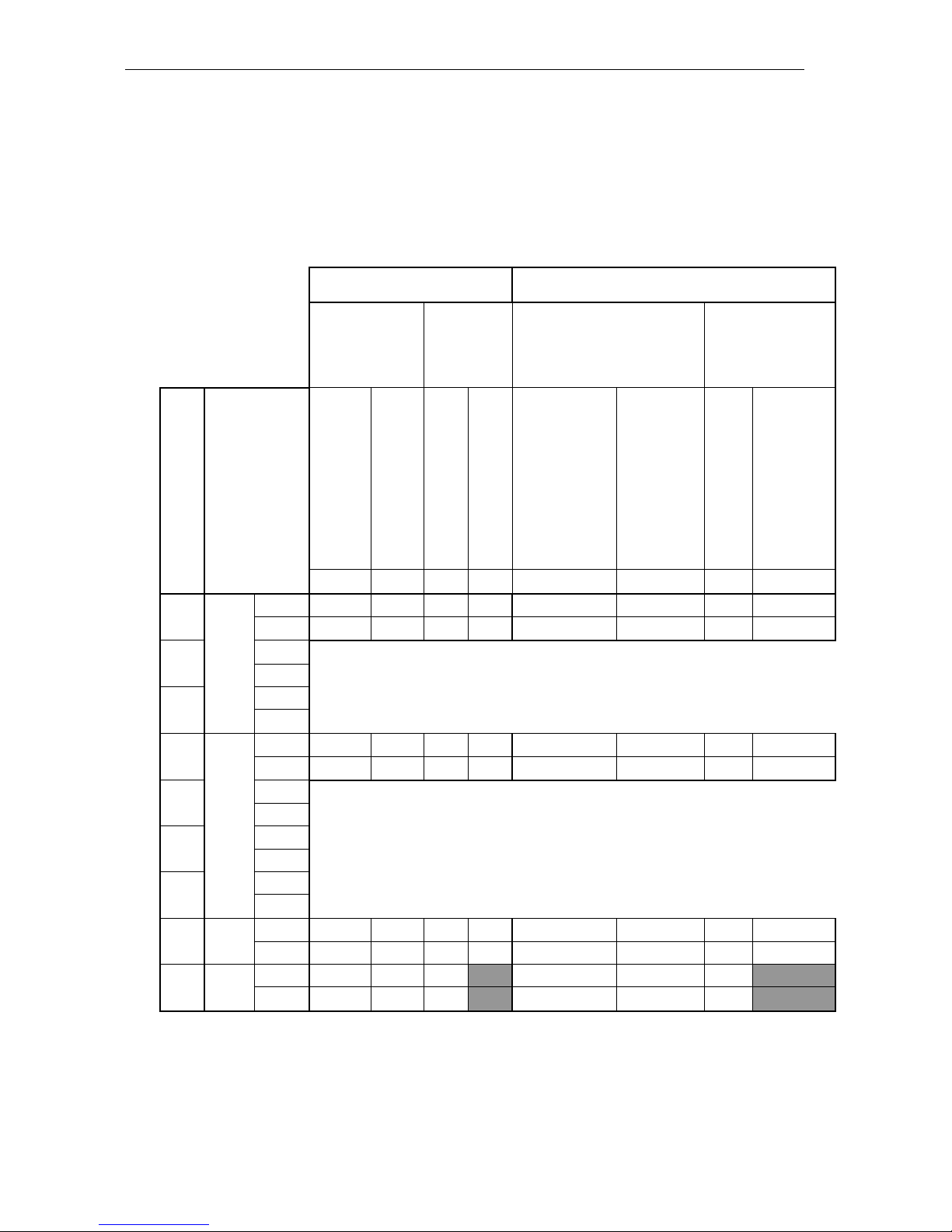
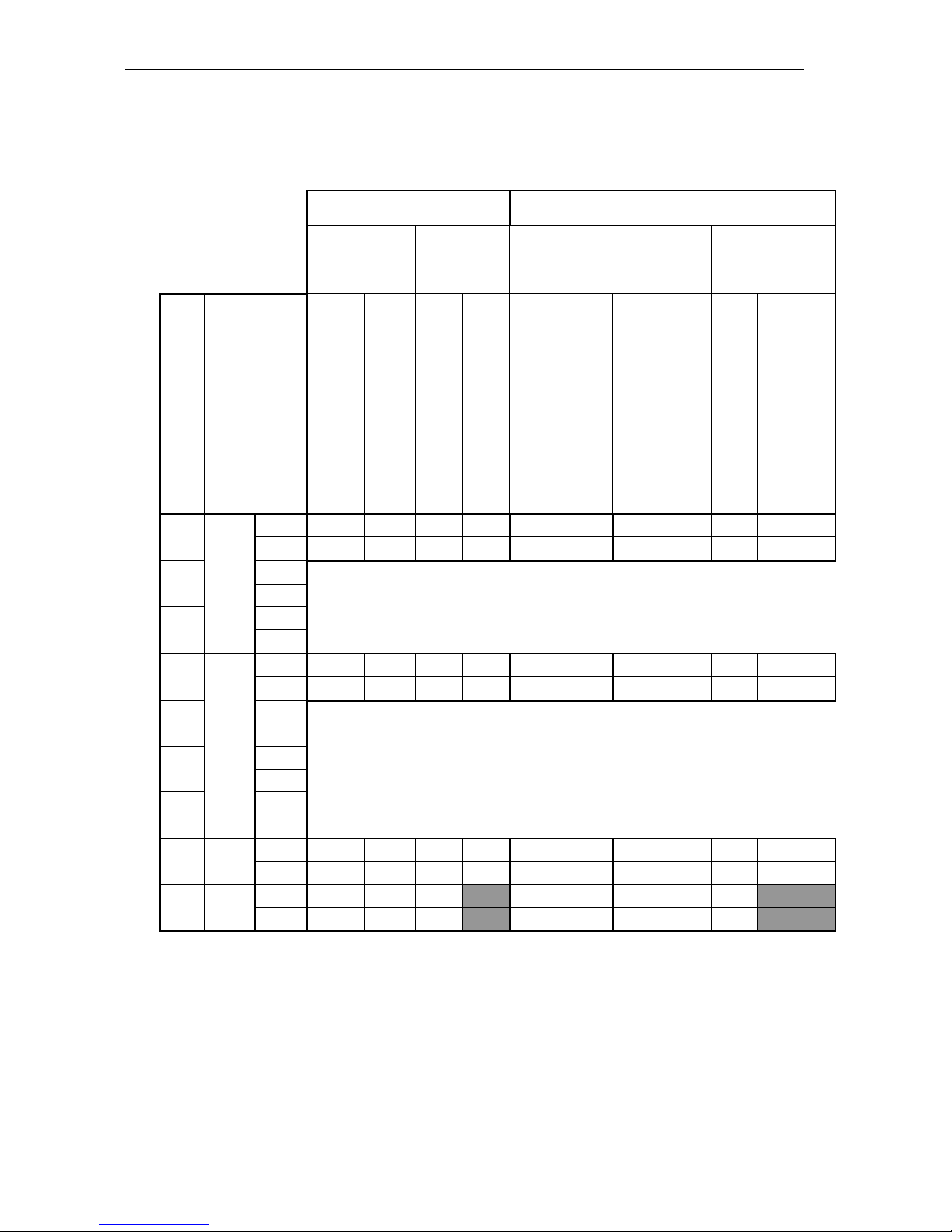
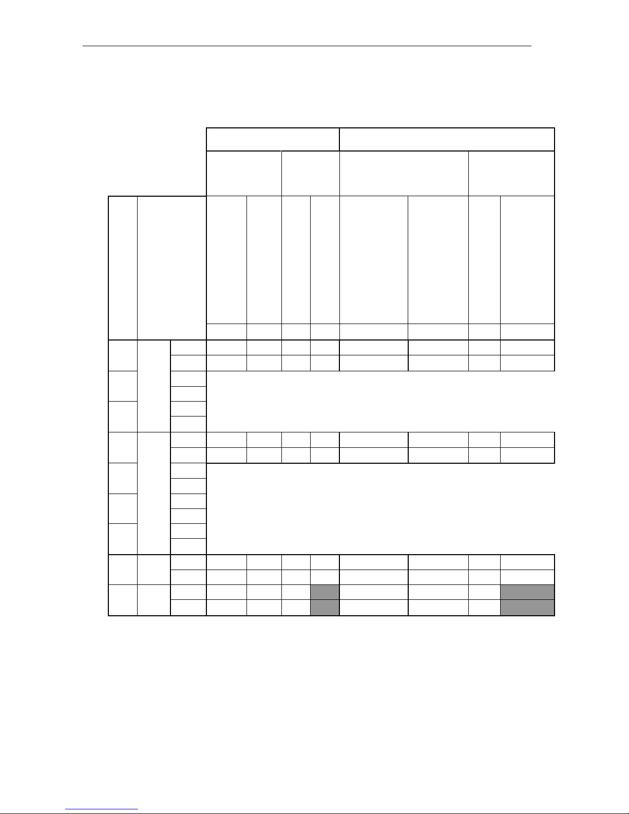
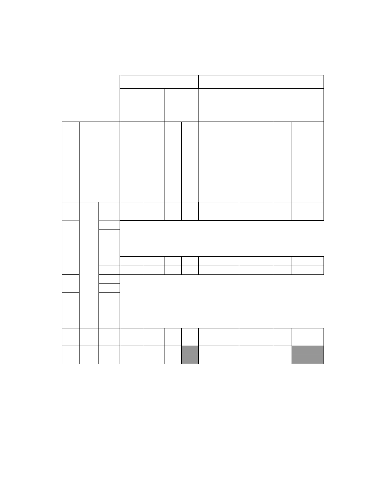
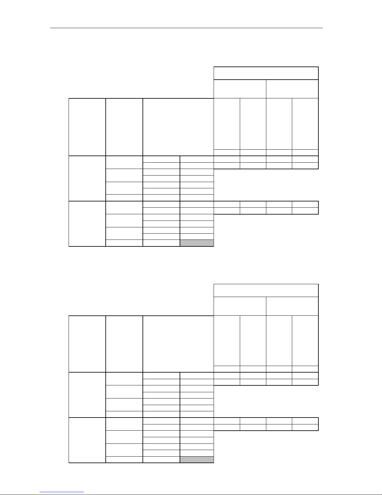
Calculated speeds (km/h) of the MTZ tractors of the series 900 with a speed-reducing
u n i t:
Rated engine rotational speed, rpm: 1800
Rear tyres: 18.4R34
Synchronized splitter
V tr with a mechanical
speed-reducing unit, km/h
V tr with a hydraulic speed-reducing unit, km/h
Mechanical
speed-
reducing unit
range I
Mechani-
cal speed-
reducing
unit range
II
Hydraulic speed-reducing
unit range I
Hydraulic speed-
reducing unit
range II
Gear No.
Range No.
V tr,
km/h
1st gear of the mechanical
speed-reducing unit
2nd gear of the mechanical
speed-reducing unit
1st gear of the mechanical
speed-reducing unit
2nd gear of the mechanical
speed-reducing unit
1st gear of the hydraulic
speed-reducing unit
2nd gear of the hydraulic
speed-reducing unit
1st gear of the hydraulic
speed-reducing unit
2nd gear of the hydraulic
speed-reducing unit
4.28
1.44
1.03
0.34
4.28
1.44
1.03
0.3
1
I
2.0
0.47
1.4
2.0
5.9
0…
0.5
0.8…
1.4
2.0
6.0
2.7
0.6
1.8
2.6
7.8
0.12…
0.6
1.2…
1.8
2.6
7.9
2
5.8
7.7 3 6.9
9.1
1
II
3.4
0.8
2.4
3.3
10.0
0.3…
0.8
1.7…
2.4
3.34
10.0
4.5
1.1
3.1
4.4
13.3
0.5…
1.1
2.3…
3.1
4.4
13.3
2
9.9
13.1
3
11.7
15.5
4
21.8
28.8
1R I 4.2
1.0
3.0
4.1
12.4
0…
1.0
0…
3.0
4.1
12.4
5.6
1.3
3.9
5.4
16.4
0.3…
1.3
0.3…
3.9
5.4
16.4
2R
II
7.2
1.7
5.0
7.0 0.6…
1.7
0.6…
5.0
7.0
9.5
2.2
6.6
9.2 1.1…
2.3
1.1…
6.7
9.2
Page 24
Specifications
MTZ series 900
24
Rated engine rotational speed, rpm: 2200
Rear tyres: 18.4R34
Synchronized splitter
V tr with a mechanical
speed-reducing unit, km/h
V tr with a hydraulic speed-reducing unit, km/h
Mechanical
speed-
reducing unit
range I
Mechanical
speed-
reducing
unit range II
Hydraulic speed-reducing
unit range I
Hydraulic
speed-reducing
unit range II
Gear No.
Range No.
V tr, km/h
1st gear of the mechanical
speed-reducing unit
2nd gear of the mechanical
speed-reducing unit
1st gear of the mechanical
speed-reducing unit
2nd gear of the mechanical
speed-reducing unit
1st gear of the hydraulic
speed-reducing unit
2nd gear of the hydraulic
speed-reducing unit
1st gear of the hydraulic
speed-reducing unit
2nd gear of the hydraulic
speed-reducing unit
4.28
1.44
1.03
0.34
4.28
1.44
1.03
0.3
1
I
2.5
0.6
1.7
2.4
7.2
0…
0.6
0.8…
1.7
2.4
7.2
3.2
0.8
2.3
3.1
9.5
0.1…
0.8
1.2…
2.39
3.1
9.5
2
7.1
9.34
3
8.4
11.1
1
II
4.2
1.0
2.9
4.1
12.3
0.3…
1.0
1.7…
2.9
4.1
12.3
5.5
1.3
3.8
5.4
16.2
0.5…
1.3
2.3…
3.8
5.4
16.2
2
12.1
16.0
3
14.3
19.0
4
26.6
35.2
1R I 5.2
1.2
3.6
5.0
15.2
0…
1.24
0…
3.6
5.0
15.2
6.8
1.6
4.7
6.6
20.1
0.3…
1.6
0.3…
4.7
6.6
20.1
2R
II
8.8
2.1
6.1
8.5 0.6…
2.06
0.6…
6.1
8.5
11.6
2.7
8.1
11.3
1.1…
2.7
1.1…
8.1
11.3
Page 25
Specifications
MTZ series 900
25
Rated engine rotational speed, rpm: 1 8 0 0
Rear tyres: 16.9R38
Synchronized splitter
V tr with a mechanical speed-
reducing unit, km/h
V tr with a hydraulic speed-reducing unit, km/h
Mechanical
speed-reducing
unit range I
Mechanical
speed-
reducing
unit range II
Hydraulic speed-reducing
unit range I
Hydraulic speed-
reducing unit
range II
Gear No.
Range No.
V tr, km/h
1st gear of the mechanical
speed-reducing unit
2nd gear of the mechanical
speed-reducing unit
1st gear of the mechanical
speed-reducing unit
2nd gear of the mechanical
speed-reducing unit
1st gear of the hydraulic
speed-reducing unit
2nd gear of the hydraulic
speed-reducing unit
1st gear of the hydraulic
speed-reducing unit
2nd gear of the hydraulic
speed-reducing unit
4.28
1.44
1.03
0.34
4.28
1.44
1.03
0.3
1
I
2.1
0.5
1.4
2.0
6.1
0…
0.5
0.8…
1.4
2.0
6.1
2.8
0.6
1.9
2.7 0.1…
0.6
1.2…
1.9
2.7
8.1
2
6.0
8.0 3 7.1
9.5
1
II
3.5
0.8
2.5
3.4
10.4
0.3…
0.8
1.7…
2.5
3.4
10.4
4.7
1.1
3.3
4.6
13.8
0.5…
1.1
2.3…
3.26
4.6
13.8
2
10.3
13.6
3
12.2
16.1
4
22.6
30.0
1R
I
4.4
1.0
3.0
4.3
12.9
0…
1.0
0…
3.0
4.3
13.0
5.8
1.4
4.0
5.6
17.1
0.3…
1.4
0.3…
4.0
5.6
17.1
2R
II
7.5
1.7
5.2
7.3 0.6…
1.7
0.6…
5.2
7.3
9.9
2.3
6.9
9.6 1.1…
2.3
1.1…
6.9
9.6
Page 26
Specifications
MTZ series 900
26
Rated engine rotational speed, rpm: 2200
Rear tyres: 16.9R38
Synchronized splitter
V tr, with a mechanical
speed-reducing unit, km/h
V tr with a hydraulic speed-reducing unit, km/h
Mechanical
speed-
reducing unit
range I
Mechani-
cal speed-
reducing
unit range
II
Hydraulic speed-reducing
unit range I
Hydraulic speed-
reducing unit
range II
Gear No.
Range No.
V tr, km/h
1st gear of the mechanical
speed-reducing unit
2nd gear of the mechanical
speed-reducing unit
1st gear of the mechanical
speed-reducing unit
2nd gear of the mechanical
speed-reducing unit
1st gear of the hydraulic
speed-reducing unit
2nd gear of the hydraulic
speed-reducing unit
1st gear of the hydraulic
speed-reducing unit
2nd gear of the hydraulic
speed-reducing unit
4.28
1.44
1.03
0.34
4.28
1.44
1.03
0.3
1
I
2.5
0.6
1.8
2.5
7.5
0…
0.6
0.8…
1.8
2.5
7.5
3.4
0.8
2.3
3.3
10.0
0.1…
0.8
1.2…
2.3
3.3
9.9
2
7.4
9.8
3
8.7
11.6
1
II
4.3
1.0
3.0
4.2
12.8
0.3…
1.0
1.7…
3.0
4.2
12.8
5.7
1.3
4.0
5.6
16.9
0.5…
1.3
2.3…
4.0
5.6
16.9
2
12.6
16.6
3
14.9
19.7
4
27.7
36.6
1R I 5.4
1.3
3.7
5.2
15.8
0…
1.3
0…
3.7
5.2
15.8
7.1
1.7
5.0
6.9
20.9
0.3…
1.7
0.3…
5.0
6.9
20.9
2R
II
9.1
2.1
6.3
8.9 0.6…
2.1
0.6…
6.3
8.9
12.1
2.8
8.4
11.7 1.1…
2.82
1.1…
8.4
11.7
Page 27
Specifications
MTZ series 900
27
Rated engine rotational speed, rpm: 1 8 0 0
Rear tyres: 16.9R38
Reverse gear
V tr, with a mechanical speed-reducing
unit, km/h
Mechanical speed-
reducing unit range I
Mechanical speed-
reducing unit range
II
Motion
Gear No.
Range No.
V tr, km/h
1st gear of the
mechanical
speed-reducing
unit
2nd gear of the
mechanical
speed-reducing
unit
1st gear of the
mechanical
speed-reducing
unit
2nd gear of the
mechanical
speed-reducing
unit
4.28
1.44
1.03
0.34
front
1 I 2.8
0.6
2.0
2.7
8.1 II
4.7
1.1
3.3
4.6
13.8 2 I
8.0
II
13.6
3 I 9.5
II
16.11
4 30.0
rear
1 I 2.6
0.6
1.8
2.5
7.6
II
4.4
1.0
3.0
4.3
12.9
2 I 7.5
II
12.7
3 I 8.8 II
15.0
4
Rated engine rotational speed, rpm: 2200
Rear tyres: 16.9R38
Reverse gear
V tr, with a mechanical speed-reducing
unit, km/h
Mechanical speed-
reducing unit range I
Mechanical speed-
reducing unit range
II
Motion
Gear No.
Range No.
V tr, km/h
1st gear of the
mechanical
speed-reducing
unit
2nd gear of the
mechanical
speed-reducing
unit
1st gear of the
mechanical
speed-reducing
unit
2nd gear of the
mechanical
speed-reducing
unit
4.28
1.44
1.03
0.34
front
1 I 3.4
0.8
2.3
3.3
10.0
II
5.7
1.3
4.0
5.6
16.9
2 I 9.8
II
16.6
3 I 11.6
II
19.7 4
36.6
rear
1 I 3.1
0.7
2.2
3.1
9.2 II
5.4
1.3
3.7
5.2
15.7
2 I 9.1
II
15.5
3 I 10.8
II
18.4
4
Page 28
Specifications
MTZ series 900
28
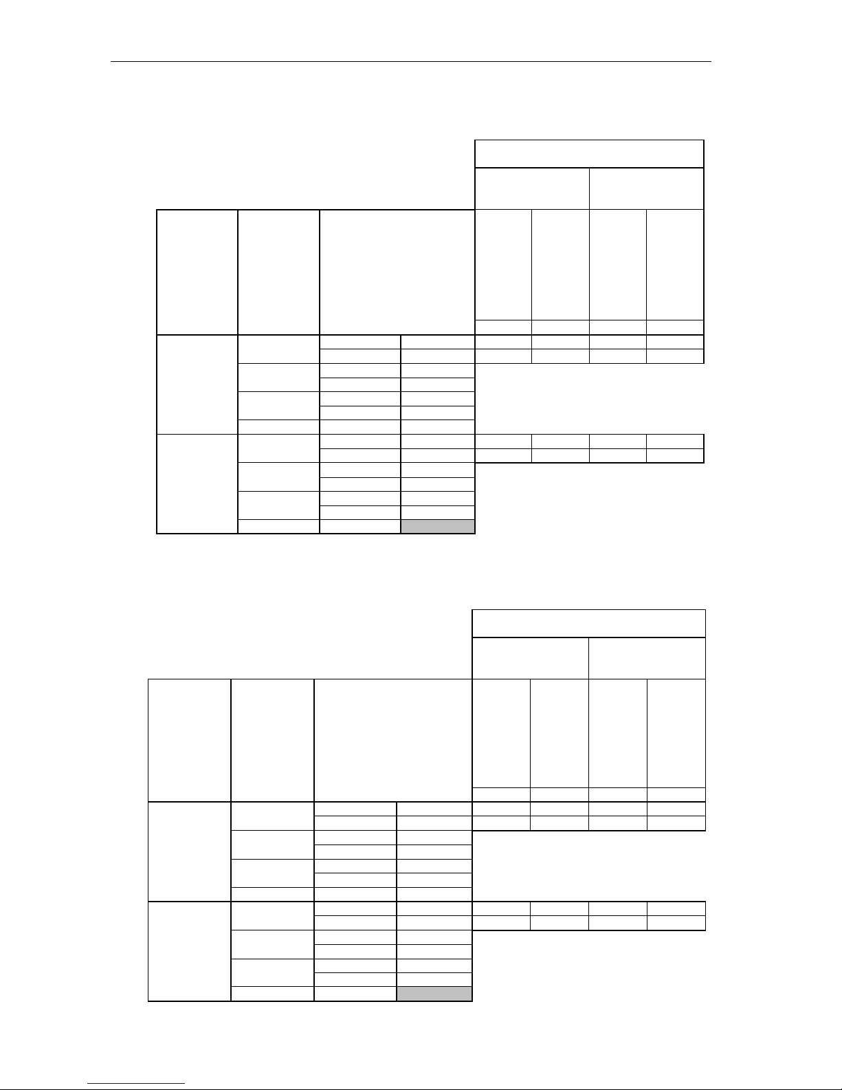
Rated engine rotational speed, rpm: 1 8 0 0
Rear tyres: 18.4R34
Reverse gear
V tr, with a mechanical speed-reducing
unit, km/h
Mechanical speed-
reducing unit range I
Mechanical speed-
reducing unit range
II
Motion
Gear No.
Range No.
V tr, km/h
1st gear of the me-
chanical speed-
reducing unit
2nd gear of the
mechanical speed-
reducing unit
1st gear of the me-
chanical speed-
reducing unit
2nd gear of the
mechanical speed-
reducing unit
4.28
1.44
1.03
0.34
front
1 I 2.7
0.6
1.8
2.6
7.8
II
4.5
1.1
3.1
4.4
13.3
2 I 7.7
II
13.1
3 I 9.1
II
15.5
4 28.8
rear
1 I 2.5
0.6
1.75
2.4
7.3
II
4.2
1.0
2.9
4.1
12.4
2 I 7.2
II
12.2 3 I
8.5 II
14.5 4
Rated engine rotational speed, rpm: 2200
Rear tyres: 18.4R34
Reverse gear
V tr, with a mechanical speed-reducing
unit, km/h
Mechanical speed-
reducing unit range
I
Mechanical speed-
reducing unit range
II
Motion
Gear No.
Range No.
V tr, km/h
1st gear of the me-
chanical speed-
reducing unit
2nd gear of the
mechanical speed-
reducing unit
1st gear of the me-
chanical speed-
reducing unit
2nd gear of the
mechanical speed-
reducing unit
4.28
1.44
1.03
0.34
front
1 I 3.2
0.8
2.6
3.1
9.5
II
5.5
1.3
3.8
5.4
16.2 2 I
9.4
II
16.0 3 I
11.1
II
19.0
4 35.2
rear
1 I 3.0
0.7
2.1
3.0
9.0
II
5.2
1.2
3.61
5.0
15.2
2 I 8.8
II
15.0
3 I 10.4 II
17.7 4
Page 29

Specifications
MTZ series 900
29
Synchronized splitter (reducing gear)
Type: mechanical, synchronized, with
direct drive and retarding gear. Located
between the clutch and gearbox and
controlled by the lever under the steering column. Allows reducing speed at
each gear 1.32 times and obtaining 14
forward gears and 4 reverse gears.
Synchronized multiplier
Type: mechanical, synchronized, with
direct drive and multiplying gear. Located between the clutch and gearbox and
allows increasing speed at each gear
1.32 times.
Reverse gear (optional)
Type: mechanical, synchronized, with
forward motion and reverse (i=-1.07 or
i=-1.88). Installed instead of step-down
reducing gear and allows obtaining 9
forward gears and 8 reverse ones.
Speed-reducing unit (optional)
Type: mechanical, two-range, two-
speed. It allows super low speeds to be
obtained. Installed instead of left cover
of the gearbox and allows obtaining additionally 16 forward gears and 16 reverse ones.
Important! When using the speedreducing unit, engage only the 1st gear
in the gearbox and the 1st reverse gear
(I-I and I-R).
Page 30

Specifications
MTZ series 900
30
Rear axle
Main gear: a pair of bevel gears with
circular sprocket teeth.
Final drive: a pair of cylindrical gears.
Differential: conical, four-satellite type.
Differential lock mechanism: hydraulic,
dry, friction coupling or multi-disk friction
coupling of ―wet‖ type (optional).
Brakes
Service: rear wheels: dry two- and three-
disk type with mechanical servo drive. Disk
diameter: 204 m m (o r 8-disk type operating
in an oil bath ( o ptional))
Parking: dry disk-type with mechanical
manual drive. Disk diameter: 180 m m (o r 4disk type operating in an oil bath ( o ptional)).
Front driving axle
Type : portal, with sliding housings of bevel
reducing gears (MTZ-920/952) or portal,
with non-sliding bar, with planetary reduc ing gears (MTZ-920.2/952.2/920.3/952.3)
Main gear: bevel gears with auger teeth.
Differential type: self-locking, of higher
friction.
Final drive: wheel reduction gears with
straight bevel pairs (MTZ-
920.2/952.2/920.3/952.3).
Transmission oils: Тап-15В, ТСп-15К o r
ТСп-10 (SAE 80W-90); ТАД-1 7 И.
Drive: from transfer gear by two cardan
shafts with intermediate support.
FDA control: mechanical, by the lever for
operator’s right hand.
3 operating modes:
FDA is DISENGAGED;
FDA is ENGAGED forcedly;
F D A is ENGAGED/DISENGAGED auto matically.
Power take-off shaft (PTO) drive
Type: independent two-speed and syn-
chronous.
Master clutch: planetary reducing gear
with band brakes.
PTO control: mechanical (electro-
hydraulic – for tractors with a hydraulic
lift) by means of the lever at the rightside control board.
PTO coupler shank speed:
Independent drive:
• 540 rpm at 2081 rpm of the diesel engine (MTZ-900/920);
• 540 rpm at 1632 pm of the diesel engine (MTZ-950/952);
• 1000 rpm at 2302 pm of the diesel engine (MTZ-900/920)
• 1000 rpm at 1672 pm of the diesel engine (MTZ-950/952)
Synchronous drive: 4.76 revolu-
tions/metre of travel with the rear tyres
16,9R38 mounted.
Removable PTO coupler shank: in accordance with the SAE standard with 6
splines for 540 rpm and 21 splines for
1000 rpm.
Rotation: clockwise as seen from the
shaft butt.
Hydraulic system
Type: universal, unit-principal, with in-
dependent power cylinder (MTZ900/920/950/952) or with hydraulic lift,
with two self-contained cylinders
(MTZ-900.3/920.2/920.3/
950.3/952.2/952.3).
Maximum pressure in the hydraulic
system: 18...20 MPa.
Distributor: spool valve type:
• Р80-3/4-222-ЗГг (Р80-3/4-111-ЗГг op-
tional);
• Р70-1221C; RS213 MTZ — for tractors
with power governor;
• РП70-1221; RS213 Mita flow-type —
for tractors with hydraulic lift.
Hydraulic system outlets: two side
and one rear outlets (drain one – optional).
RMA control system has three operating modes:
• power;
• position;
• high-altitude.
Hydraulic system oil brands:
BECHEM Stariol №32;
ADDINAL Hydraulikol HLP 32;
THK Hydraulic HLP32.
Rear mounted attachment
Type: three-point mounted system of
category 2
Page 31

Specifications
MTZ series 900
31
Lifting capacity: 3000 kg at the ends of
longitudinal rods
Electrical equipment
Voltage: 12 V.
Start system voltage: 12 V or 24 V.
Power supply system: two storage bat-
teries, 12 V each, connected in parallel
(series connection when starting the engine for supplying the starter with the
voltage of 24 V).
Alternator
14 V, 1000 W (1150 W – for MTZ-
900.3/920.3/950.3/952.3).
Lighting system and light alarm:
• front headlights with lower and distance light;
• front and rear work lights;
• clearance and brake lights;
• dashboard, cab and number plate light-
ing;
• emergency warning lights;
• road-train sign.
Pneumatic system
Compressor
Type: single-cylinder, air-cooled.
Trailer brake control actuator
Type: pneumatic, single-ended, inter-
locked with tractor brakes.
Twin actuator – for MTZ-
900.3/920.3/950.3/952.3
Pressure restricted by safety valve:
0.65…0.80 MPa.
Wheels
Front:
9.00R20 or 9.0-20 (MTZ900/900.3/950/950.3) main;
13.6-20 (MTZ-920/952) main;
11.2-20 (MTZ-920/952) optional;
360/70R24 (MTZ-920.2/920.3/
952.2/952.3) main.
Rear:
16,9R38 (MTZ-920/952) main;
18,4R34 (MTZ- /920.3/952.2/
952.3) main;
18,4R34 (Ф-11) (MTZ-900/
900.3/920.2/950/950.3) main.
Other equipment
Front and rear wipers, cab heating and
ventilation system, windshield washer,
cab lighting dome, air conditioner (optional).
Page 32
Controls and Instrumentation
MTZ series 900
1
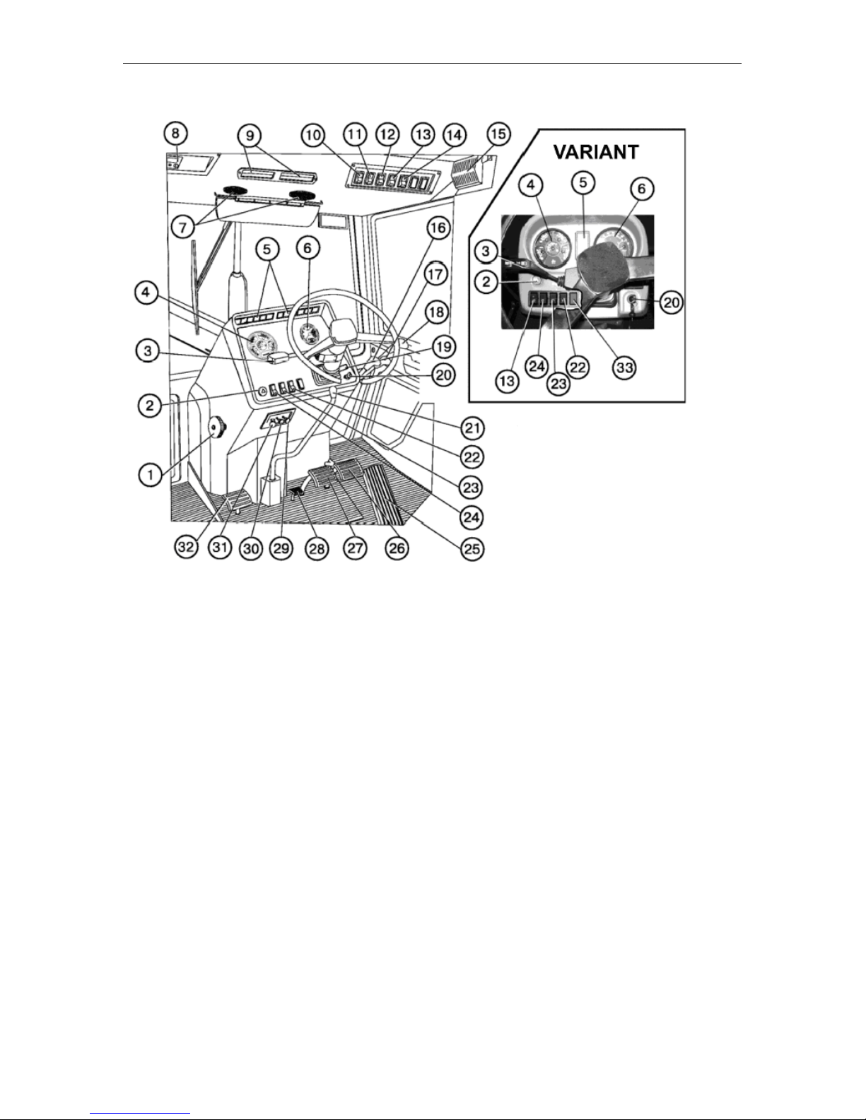
CONTROLS AND INSTRUMENTATION
1. Cooling system radiator shutter control.
2 . Emergency control lamps switch.
3 . Steering-wheel-mounted multifunction
switch (turn, turn indicators, upper/lower beam).
4. Combination meter.
5. Control lamps block.
6 . Electric tachospeedometer.
7 . Air distributors.
8 . Radio receiver (if installed).
9 . Recirculation shutters.
10. Windscreen wiper switch.
11. Cab fan and heater switch.
12. Rear working lights switch.
1 3 . Front working lights switch.
1 4 . Road-train sign lighting switch.
15. Cab light switch.
16. Control of the left-side outputs of the
hydraulic system.
17. Control of the right-side outputs of
the hydraulic system.
18. Control of the left rear outputs of the
hydraulic system.
1 9 . Tachospeedometer control board.
2 0 . Starter and instrumentation switch.
21. Control of the step-down reduction
gear and shuttle gear (if installed).
2 2 . Starting aid switch (for tractors
equipped with an electric torch preheater).
2 3 . Windscreen washer switch.
2 4 . Clearance lights and headlights
switch.
2 5 . Fuel feed control pedal.
2 6 . Right service brake pedal.
2 7 . Left service brake pedal.
2 8 . Rear axle differential lock control.
29. Steering column inclination control.
30. Engine shutdown cord handle
31. Cab heater valve control (if installed).
32. Clutch pedal.
33. Plug.
Page 33
Controls and Instrumentation
MTZ series 900
2
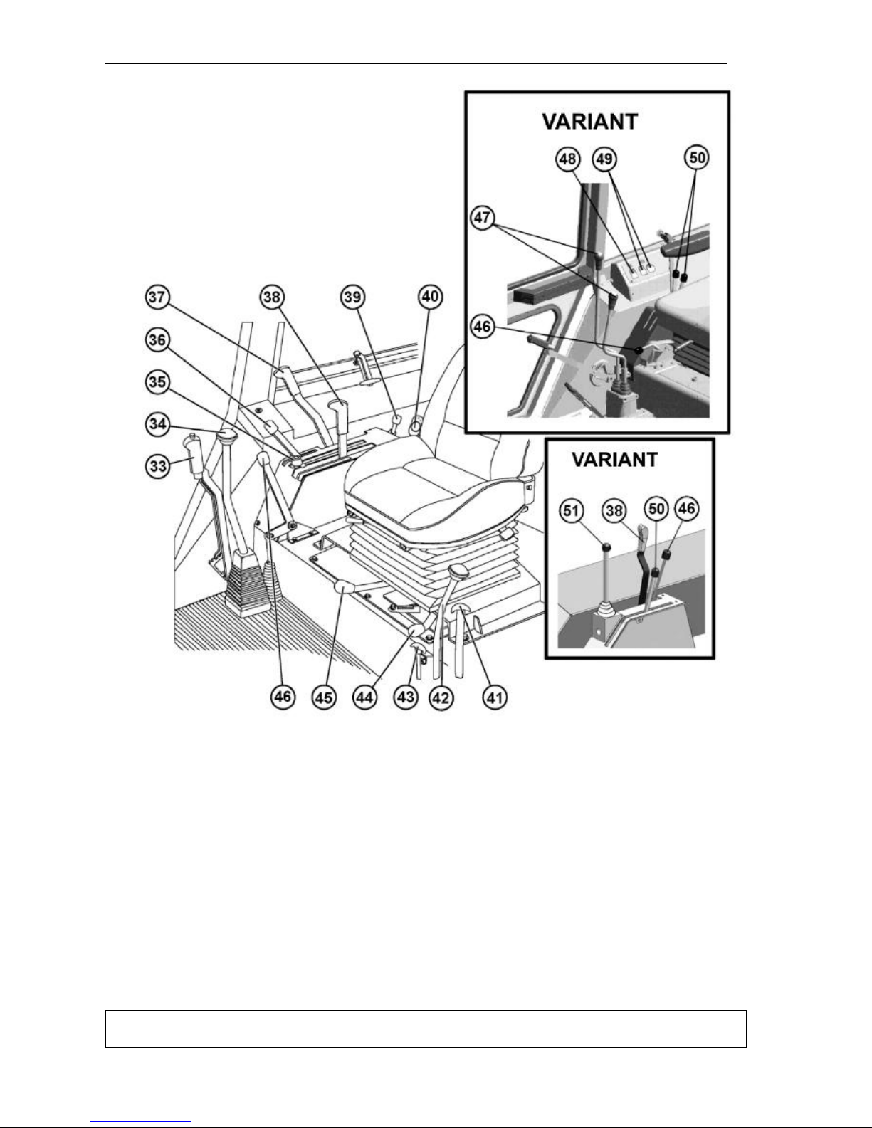
33. Parking brake lever.
34. Gearbox control lever.
35. Stop bumper of power governor control lever.
36. Fuel feed control arm.
37. PTO control lever.
38. Power governor control arm.
39. Signal switch arm of power and position control sensors (if installed).
40. SB switch (on the MTZ-
900.3/920.3/950.3/952.3 tractors, the SB
switch is located under the bonnet in the
SB zone)
41. Speed-reducer gear switch arm (if
installed).
42. Speed-reducer gear range switch
arm (if installed).
43. Control handle of the hydraulic hook
claws.
44. PTO switch arm (independent/synchronized).
45. Arm for fixing the hinging mechanism
in the lifted position (version with a power
governor) .
46. FDA drive control arm.
47. Gearbox control levers.
48. Rear axle differential lock control
49. PTO control
50. Hydraulic hoist control levers
51. Joy stick for remote control of the hydraulic system distributor (if installed)
IMPORTANT! Prior to working on the tractor, study the controls and instrumentation
and their functions.
Page 34
Controls and Instrumentation
MTZ series 900
3
Instrumentation and Switches
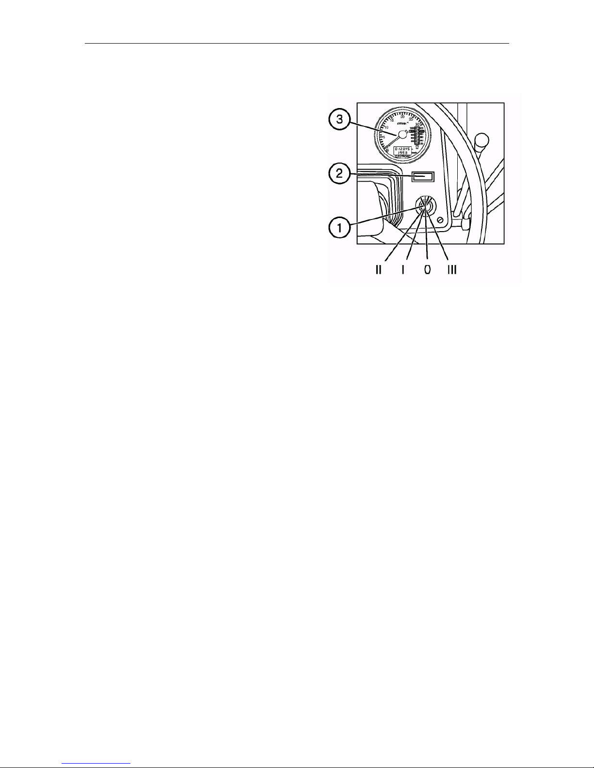
Starter and instrumentation switch (1)
Switch (1) has four positions:
• 0 – “Off”
• I – “Consuming units On”
• II – “Starter On” (not fixed)
• III – “ R adio receiver ON” (key turned counter-
clockwise)
Page 35
Controls and Instrumentation
MTZ series 900
4
1. Instrumentation
The schematics of the instrument dashboards 80-3805010-Д1 and 826-3805010 are giv-
en in the section “Appendix”.
The instrumentation includes:
- the combination meter (Р2) with sensors;
- the electric tachospeedometer (Р1) with the control board (А3) and sensors;
- the electric light and audible alarms combined into two pilot lamp units (HG1 and HG2)
in the instrument dashboard 80-3805010-Д1 or into the pilot lamp unit and combination
meter in the instrument dashboard 826-3805010.
To switch on the instruments, turn the starter and instrumentation switch to the “I” position. Then the voltage will be applied to the terminal “K3” of the switch, then to the relay
for power supply of the instruments, to the fuse (F2) of the unit and further – to the units
(HG1 and HG2), tachospeedometer (Р1), alarm device (НА2), combination meter (Р1)
and speed sensors (BV1 and BV2).
The instrument pointers shall move to the zero position or to the position corresponding
to the true value of the parameter controlled by the system at the moment.
In case of deviation of readings of the instruments from their true values, detect the
cause of the fault following the recommendations below.
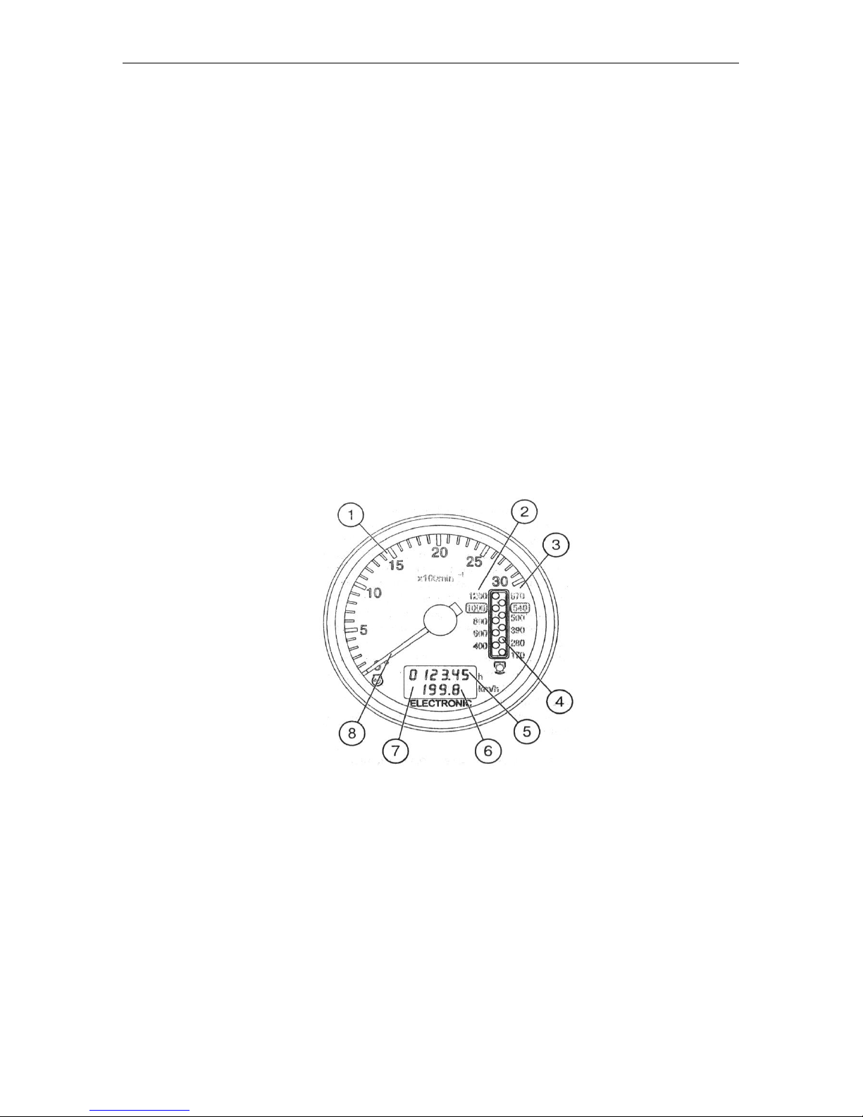
1.1. Tachospeedometer АР70.3813 (Fig. 1)
Fig. 1. Tachospeedometer (Р1):
1 . Engine crankshaft rotational speed scale, rpm.
2 . PTO II rotational speed scale –1000 rpm.
3 . PTO I rotational speed scale –540 rpm.
4 . PTO rotational speed display (LED).
5 . Engine running hours indication, h.
6 . Tractor speed indication, km/h.
7 . Display of engine running hours and tractor speed, km/h.
8 . Pointer indicator of the engine crankshaft speed (LCD).
The electric tachospeedometer АР703813 installed in the dashboard operates as follows:
• On setting the starter and instrument switch is put to position I when the tractor is
stopped, the display (7) shows the engine running hours (5);
Page 36

Controls and Instrumentation
MTZ series 900
5
• When the tractor is moving, the display (7) shows the tractor speed indication (6)
(km/h), while the indication (5) disappears. The electric signal of the speed comes from
the speed sensors mounted on the rear axle cover (BV1, BV2). The speed readings are
taken through a signal from the sensor mounted on the pinion of the final drive of the
wheel rotating at lesser speed. The calculated speed is higher than the actual one, because no tractor skid is the taken into account;
• On starting the engine, the pointer indicator (8) moves round the index dial (1) to display
the rotational speed of the engine crankshaft. At the same time, the display (4) shows the
PTO indication (rpm). The scale (3) is assigned to the PTO I and the scale (2) – to the
PTO II. The electric signal of the rotational speed is taken from the phase winding of the
alternator.
1.2. Tachospeedometer control board (Fig. 2)
The control board is installed in the dashboard and serves for programming the
tachospeedometer to the specific model of the MTZ tractor.
Fig. 2. Control board (А3):
1 – Button for setting the tachospeedometer to the programming mode and selecting the
programming parameter on the tachospeedometer display (7). 2 – Button for selecting
the value of the coded parameter shown on the display (7)
1.3. Programming the tachospeedometer АР70.3813
ATTENTION! The tachospeedometer has been programmed just to your tractor make at
the factory. Re-programming is required in case of tyre type changing. Do not re-program
the tachospeedometer, if unnecessary.
The tachospeedometer shall be programmed to ensure the correct display of the following tractor’s parameters: engine rotational speed, tractor motion speed and PTO rotational speed (540 and 1000 rpm).
Programming procedure:
– Remove the control board cover;
– Press the button (1) to enter the programming mode (Fig. 2).
1. To ensure the correct display of the tractor motion speed, it is necessary to program
the tachospeedometer to the number of teeth of the pinion at the place of installation of
the speed sensors (parameter “Z”) and rear wheel rolling radius (parameter “R”). To do
this:
– press the button (1) of the board and call the parameters “Z” and “R” in turn to the display (3) of the tachospeedometer (4);
– press the button (2) of the board and set the number of teeth (Z) according to Table 1
and value Rk according to Table 2:
PARAMETER VALUE
Page 37
Controls and Instrumentation
MTZ series 900
6
Table 1
Number
of teeth
(Z)
Tractor make
69
MTZ 590; 80.1; 890; 900; 922; 950
Table 2
Tyre
mark
16,9R30
18,4L30
15,5R38
9,5-42
18,4R34
(Ф-11)
16,9R38
18,4R38
Rk, m
0.698
0.720
0.755
0.730
0.770
0.800
0.830
Number
coded
700
720
755
730
770
800
830
3. To ensure the correct display of the engine and PTO rotational speeds (540 and
1000), program the engine make (parameter “D”):
– press the button (1) and call the parameter “D” to the tachospeedometer display (3);
– press the button (3) and set the necessary engine make according to Table 3:
Table 3
Engine make
Д-243
Д-244
Д-245
Д-
245.5
Rated rotational
speed, rpm
2200
1700
2200
1800
Number pro-
grammed
243
244
245
245.5
On the expiry of seven seconds after programming, the instrument returns automatically
to the operating mode. Refit the board cover.
Note: If no information on the type of the tyre fitted is available, it is allowed to measure
the value Rk as a distance from the wheel axis to the ground prior to beginning the operation of the tractor.
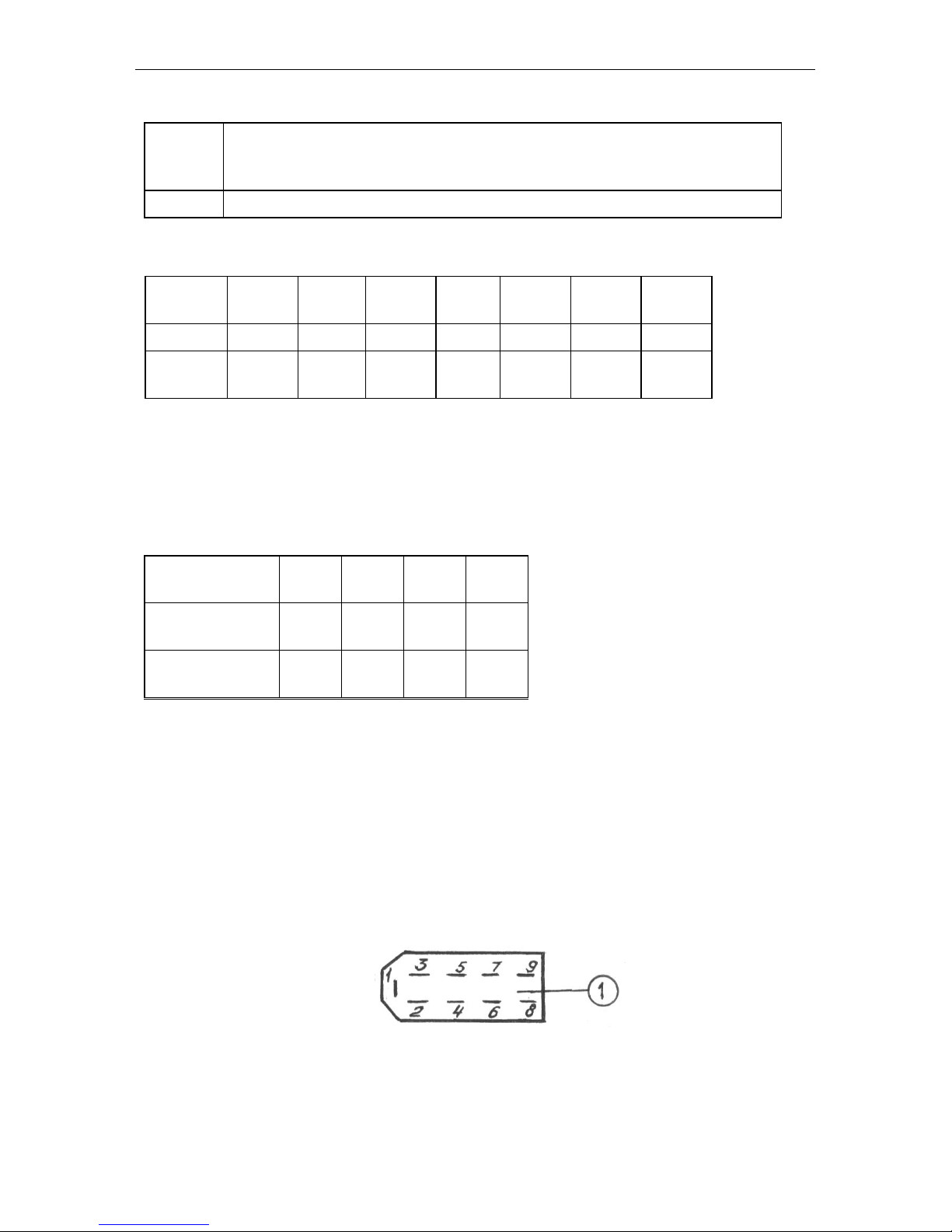
1.4. Connecting the tachospeedometer
To connect the tachospeedometer to the instrumentation system, a 9-contact block is
provided on the rear panel of the instrument (Fig. 3).
Fig. 3
Page 38

Controls and Instrumentation
MTZ series 900
7
The identification of the block pins is given in Table 4.
Table 4
Pin
Identification
1
to the terminal “–“
2
to the power supply unit “+12В”
3
to the board output “Parameter selection”
4
to the board output “Parameter value”
5
to the board output “Mode”
6
to the speed sensor BV2 (left wheel)
7
to the speed sensor BV1 (right wheel)
8
to the phase winding “W” of the alternator
9
to the instrument backlight lamps
1.5. Tachospeedometer diagnostics and troubleshooting
1. No instrument backlight:
Check the power supply wire connected to the pin “9” of the 9-contact block of the instrument (Fig. 3) – check if the backlight lamps are intact.
2. Jerking and jumps of the pointer of the engine rotational speed indicator over
the dial: poor contact on the alternator terminal and, therefore, poor signal from the
phase winding of the alternator. Repair.
3. Jerking of the pointer and understating the reading of the engine rotational
speed:
- Check and adjust the tension of the alternator driving belt.
4. Over- or understated readings of the engine and PTO’s rotational speeds (with
the normal movement of the pointer):
- Check the correctness of programming the instrument according to the engine make
(parameter “D”): (see item 1.3);
5. The counter of astronomical hours of the engine running fails to accumulate the
operating time: Check the connection of the wire to the contact “8” of the instrument
block and the presence of the frequency signal from the phase winding of the alternator.
6. Over- or understated readings of the tractor speed:
- Check the correctness of the instrument programming according to the rolling radius of
the rear wheels (Rk) (see item 1.3);
- Check the correctness of the programming according to the number of teeth of the halfaxle pinion (Z) (see item 1.3).
7. No readings of the tractor motion speed: Check the presence of signals from both
the speed sensors (BV1, BV2).
8. The readings “02…07” km/h appear on the instrument indicator when the tractor
is moving:
- the numbers “02…07” and, 12 seconds later, “0” appear from the right side of the scale
– no signal from the right speed sensor (BV1).
- the numbers “02…07” and then “0” appear from the left side of the scale – no signal
from the left speed sensor (BV2).
Page 39
Controls and Instrumentation
MTZ series 900
8
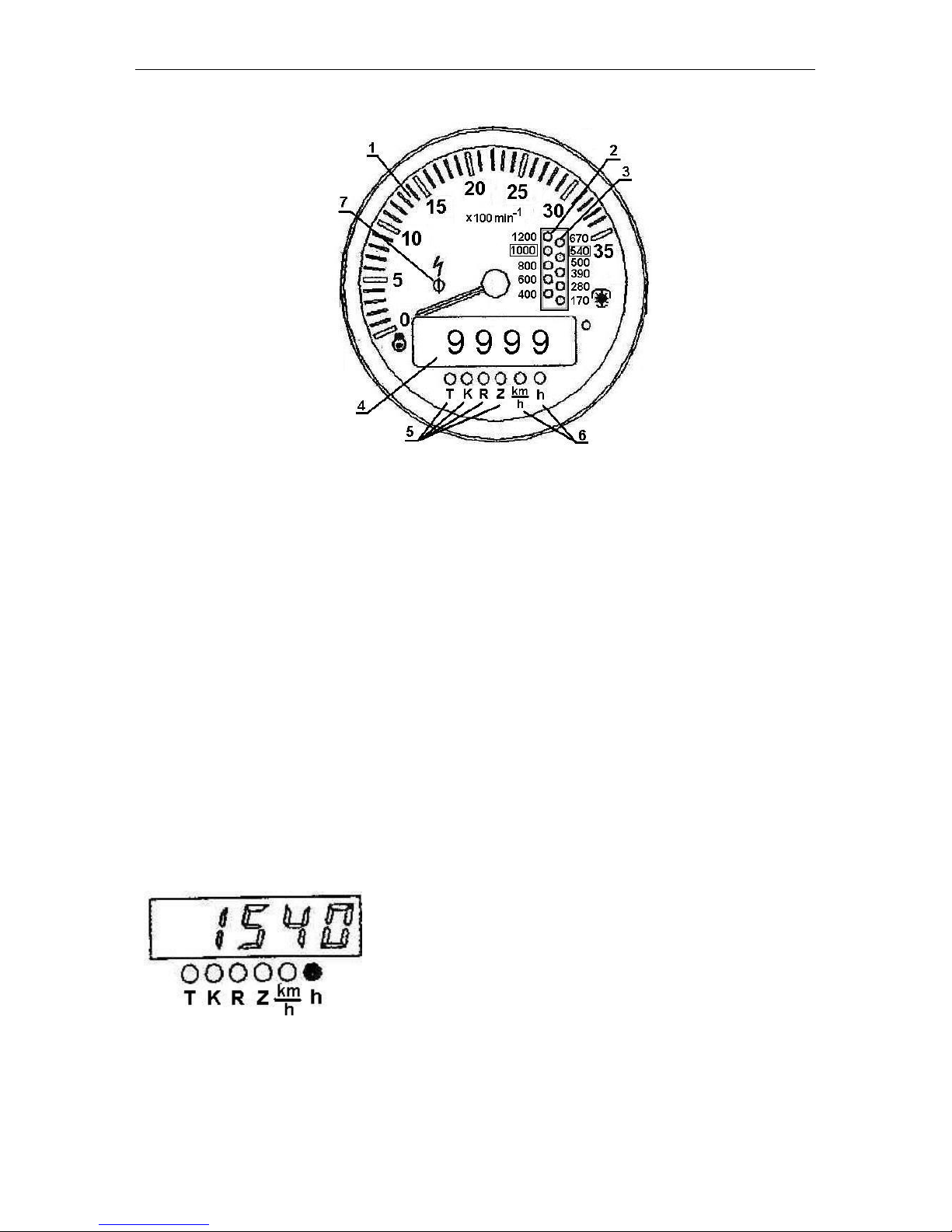
1.6. Combined indicator КД 8083
Fig. 4. Tachospeedometer (Р1):
1 – Engine rotational speed indicator (pointer indicator).
2 – PTO 1000 rotational speed scale (opposite to the respective value of the PTO ro-
tational speed).
3 – PTO 540 rotational speed scale (opposite to the respective value of the PTO rota-
tional speed).
4 – Five-digit indicator.
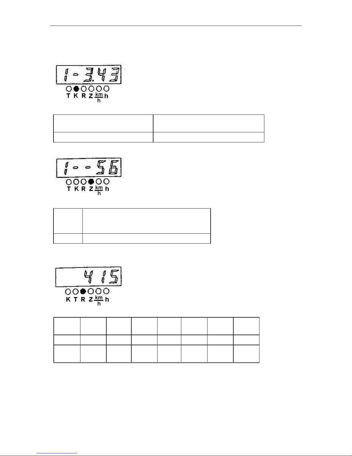
5 – LED’s lighting up in the mode of programming the coefficients “K”, “R” and “Z”
(opposite to the respective LED).
6 – LED’s lighting up in the mode of display of the motion speed “km/h” and total en-
gine running time “h” (opposite to the respective LED).
7 – Alarm of the overvoltage in the tractor on-board power system (red) operates, if
the voltage exceeds 18.5 V.
In this case the instrument is switched off because the protective device operates. Should the voltage
drop down to 16.5 V, the indicator returns to the operating state and the overvoltage indicator goes out.
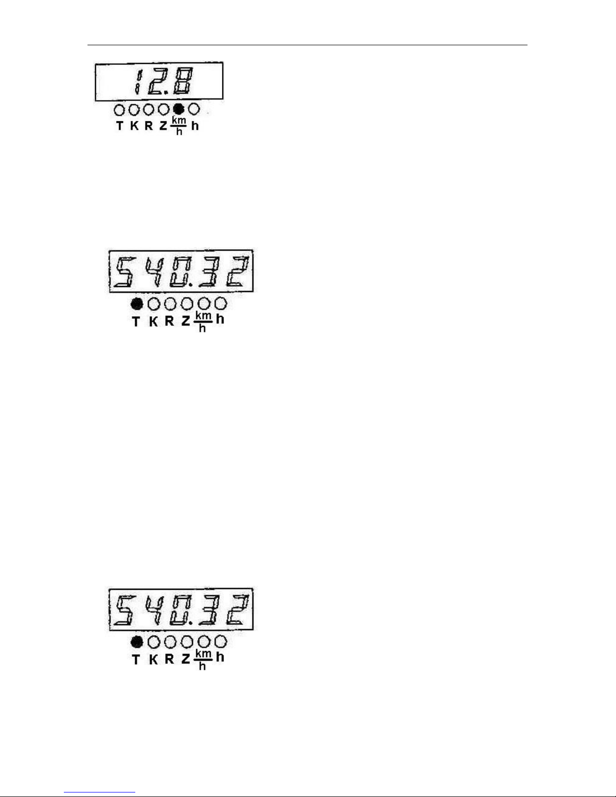
Indicator operating procedure
On switching on the power supply, the indicator is switched to the main operating
mode. In case of absence of signals from the speed sensors the digital indicator (4)
shows the reading of the total engine running time and the LED located next to the symbol “h” lights up.
Total engine running time:
Appearance of the pulses from the speed sensors at the input of the pulse indicator
causes the switching-on to the motion speed indication mode. Then the measured
calculated speed reading is shown on the digital indicator and the LED located next to
the symbol “km/h” lights up.
The calculated motion speed (km/h).
Page 40
Controls and Instrumentation
MTZ series 900
9
1.7. Programming the indicator КД8083
Programming procedure:
- remove the control board cover;
- press the button (1) of the control panel and hold it down for at least 2 seconds;
- the display (7) shows the mode “Adjusted total engine running time”. In this case, the
LED located next to the symbol “Т” lights up.
- press repeatedly the button (1) to switch over cyclically the programmable parameters;
- press the button “2” to enter the required value of the selected parameter, then the least
significant digit (the first on the right) of the selected parameter of the indicator starts
blinking with the period of 0.3 s;
- set the required value of the less significant digit of the selected parameter by pressing
the button “2”;
- press shortly the button “1”; then the second from the right digit of the digital indicator
shall start blinking;
- set the required value in the second from the right digit of the parameter to be corrected
by pressing the button “2”;
- press shortly the button “1”; then the third from the right digit of the digital indicator shall
start blinking;
- set the required value in the third from the right digit of the parameter to be corrected by
pressing the button “2”;
- fix the entered value of the parameter by pressing the button “1”;
- on pressing the button “1” next time, the switching to the next parameter will occur.
To exit the programming mode, enter the adjusted time mode, press and hold down the
button (2) for at least 2 s; then the readings “8.8.8.8.8” shall be shown in the five-digit indicator for 1-4 seconds and all the LEDs of the PTO’s scales shall light up.
Page 41
Controls and Instrumentation
MTZ series 900
10
1. To display correctly the tractor motion speed, it is necessary to program the following
parameters in the following order:
2. Gear ratio of the wheel reduction gear (parameter “K1”) from Table 5:
Table 5
Gear ratio of the wheel reduction
gear (K1)
Tractor make
1.00
MTZ 590; 80.1; 890; 900; 922; 950
according to the number of teeth at the place of installation of the speed sensors (parameter “Z1”) from Table 6:
Table 6
Number
of teeth
(Z1)
Tractor make
69
MTZ 590; 80.1; 890; 900; 922; 950
rear wheel rolling radius (parameter “R”) from Table 7:
Table 7
Tyre
mark
16,9R30
18,4L30
15,5R38
9,5-42
18,4R34
(Ф-11)
16,9R38
18,4R38
Rk, m
0.698
0.720
0.755
0.730
0.770
0.800
0.830
Number
coded
700
720
755
730
770
800
830
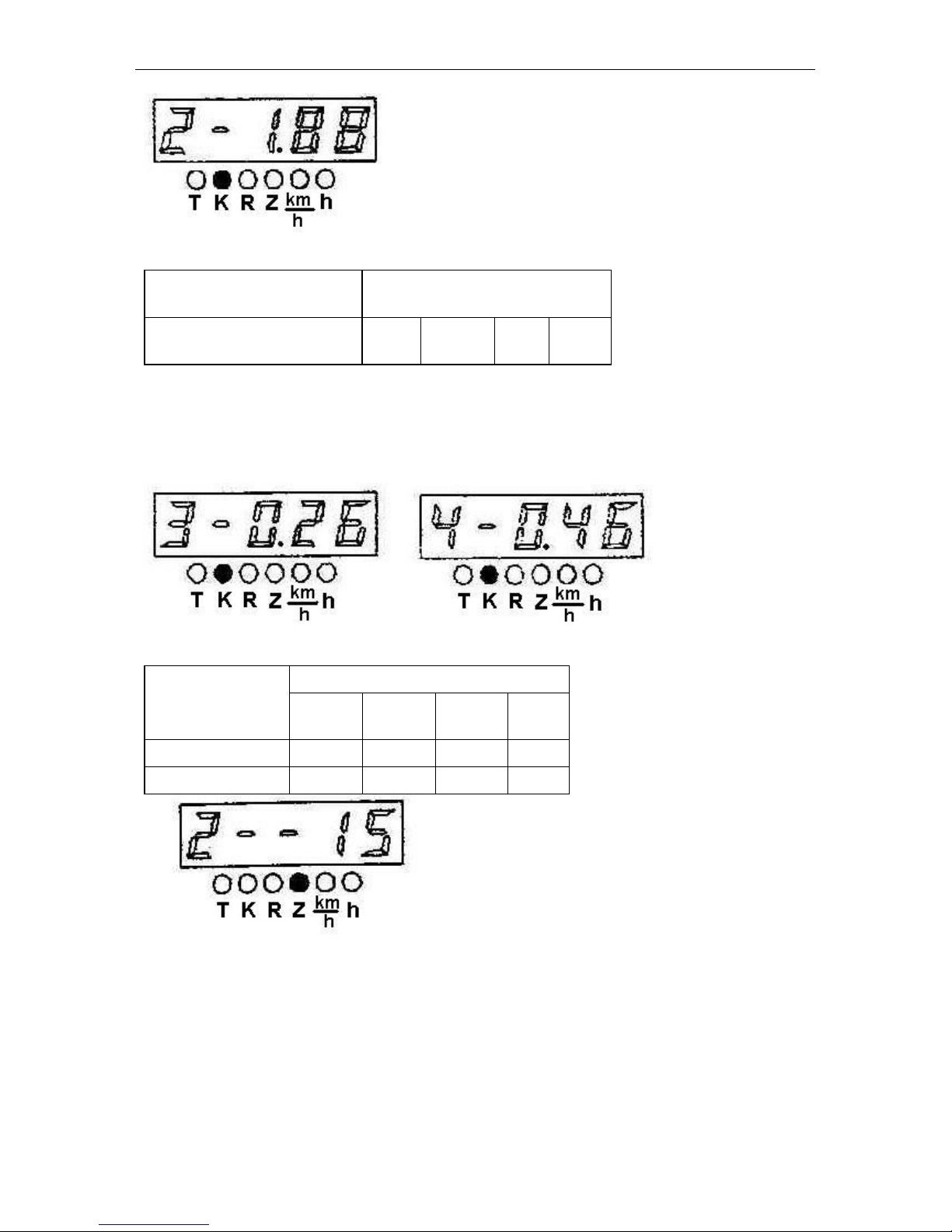
2. To display correctly the engine rotational speed, it is necessary to program the gear ratio of the alternator drive (parameter “K2”) from Table 8 in the specified order:
Page 42
Controls and Instrumentation
MTZ series 900
11
Table 8
Gear ratio of the alternator
drive (K2)
Engine mark
2.36
Д-242
Д-243
Д-245
Д-
245.5
3. To display correctly the PTO’s rotational speed (540 and 1000), it is necessary to program the gear ratios of the PTO 540 “K3” and PTO 1000 “K4” from Table 9 and the number of teeth of the pinion at the place of installation of the PTO sensor “Z2” in the specified order:
Table 9
The gear ratio of
the PTO drive
Engine mark
Д-242
Д-243
Д-245
Д-
245.5
540 (K3)
0.33
0.26
0.26
0.33
1000 (K4)
0.60
0.46
0.46
0.60
- in case of absence of the PTO rotational speed sensor (from the phase winding of the
alternator serves as that for indication of the PTO rotational speed), the entered value of
the parameter “Z2” shall be equal to 0.
Page 43

Controls and Instrumentation
MTZ series 900
12
1.8. Indicator Diagnostics and Troubleshooting
1. The diagnostics of the faults according to items 1-3 and 5 is similar to that of the
tachospeedometer;
2. Over- or understated readings of the engine rotational speed and PTO’s rotational speed (with the normal movement of the pointer):
Check the correctness of programming the instrument according to the gear ratio of the
alternator drive (parameter “K2”): (see item 1.7);
3. Over- or understated readings of the tractor speed:
1. Check the correctness of programming the instrument according to the rolling radius of
the rear wheels (R) (see item 1.7);
2. Check the correctness of programming according to the number of teeth of the halfaxle pinion (Z1) (see item 1.7);
3. Check the correctness of programming of the gear rate of the wheel reduction gear
(K1) (see item 1.7).
4. No readings of the tractor motion speed:
Check the presence of the signals from the both speed sensors (BV1, BV2).
5. Signalling of operation of the speed sensor in case of absence of a signal from
one of them:
a) in case of absence of the signal from the right wheel speed sensor (BV1), the symbol
“□” is displayed on the right of the digital indicator within 12 s after starting the motion;
check the connection and serviceability of the right wheel speed sensor;
b) in case of absence of the signal from the left wheel speed sensor (BV2), the symbol
“□” is displayed on the left of the digital indicator within 12 s after starting the motion;
check the connection and serviceability of the left wheel speed sensor.
Page 44
Controls and Instrumentation
MTZ series 900
13
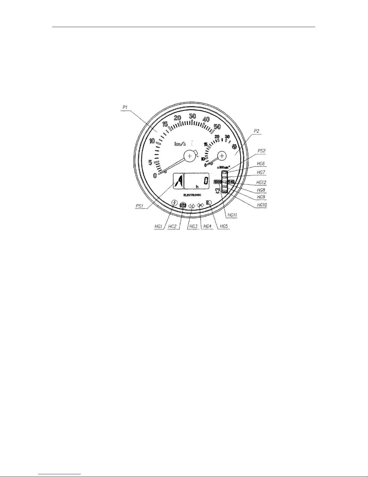
1.9. Combined indicator АР80.3813 and combined indicating unit КД8105 (mounted
on the tractors with the instrument dashboard 826-3805010)
The combined indicator (hereinafter referred to as the CI) and the control board (hereinafter referred to as the CB) monitor the operational parameters of the systems and units
of the MTZ tractors and provide the operator with the information on malfunction or failure
of a particular system.
The CI includes the indicators and alarm lamps monitoring the following parameters:
Р1 – speed indicator (pointer-type);
Р2 – engine rotational speed indicator (pointer-type);
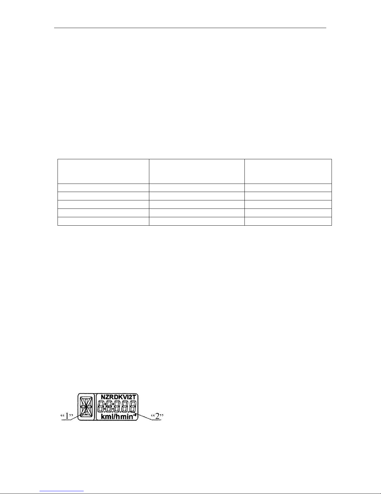
РS1 – LCD, multifunction indicator (for the description and principle of operation of the
РS1 in more detail, see below)
РS2 – PTO rotational speed indicator (light indicator);
HG1 – pilot lamp-alarm of the overvoltage in the on-board power supply system (red);
HG2 – pilot lamp-alarm of the parking brake application (red);
HG3 – pilot lamp-indicator of switching on the turn indicators of the tractor (green);
HG4 – pilot lamp-indicator of switching on the turn indicators of the trailer (green);
HG5 – pilot lamp-indicator of switching on the upper beam of the headlights (blue);
HG6, HG10 – PTO scale segments (yellow);
HG7… HG9 – PTO scale segments (green);
HG11, HG12 – scale range indicator of the PTO 1000 and 540, respectively (yellow);
Page 45
Controls and Instrumentation
MTZ series 900
14
Operating principle of the PTO rotational speed indicator:
1. In the absence of the PTO rotational speed sensor, the designations of the
“540” and “1000” scales as well as the indicator of the scale ranges HG11, HG12 light up
simultaneously on starting the engine (when a signal comes from the phase winding of
the alternator).
The indication of the PTO scale segments (with the account of the selected value
of the coefficient “KV2”) occurs on reaching the calculated PTO rotational speed equal to
750 (rpm).
For reference: the indication of the PTO scale segments occurs on reaching the
engine rotational speed of 1400-1500 (rpm) and more.
Here, depending on the selected PTO speed mode (540 or 1000), the lit PTO
scale segments designate the rotational speed values according to Table 10.
Table 10
Values of operation of the
“1000” scale segments
(rpm)
Segment location on the
scale
Values of operation of the
“540” scale segments
(rpm)
1150
HG6
650
1050
580
950
HG8
500
850
420
750*
HG10
320
2. In the presence of the PTO rotational speed sensor installed over the pinion of the
PTO shank, the combined indicator selects automatically the range (320-750 or 750-
1250) depending on the rotational speed of the shank that is accompanied visually by
switching on the backlight of the digital designation of the scale – “540” (HG11) or
«1000» (HG12), here the threshold values of operation of the scale segments change in
accordance with the requirements of Table 10.
The five LED 5 scale segments (HG6 … HG10) of the PTO light up starting from
the bottom one including the segment with the current value of the PTO rotational speed
included in the range of the lit state of that segment.
Notes:
- (*) is the rotational speed value, at which the “1000” scale designation is switched on;
- the “540” scale designation is only switched on in the presence of the signal from the
sensor and switched on switching on the “1000” designation or in case of absence of the
signal for more than 3 s.
- the exact value of the PTO rotational speed can be seen on the indicator РS1.
РS1, the LCD multifunction indicator displays simultaneously:
1. Digital designation of the position of the gearbox
control level (digits from 0 to 6) or lettering of the reduction gear switch (letters L, M, H, N);
2. Current numerical value of one of the parameters
of the tractor systems.
The combined indicator receives the information on
the position of the gearbox control lever from the
transmission control unit (if the complex electronic control system (CECS) is available) or
LCD information fields
Page 46
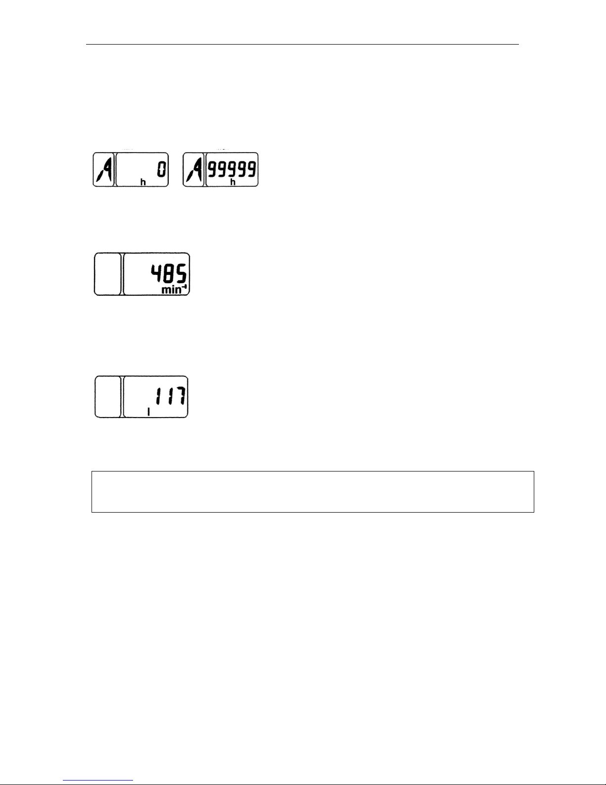
Controls and Instrumentation
MTZ series 900
15
from the control unit of the range reduction gear (if provided). This parameter is displayed
on the information field “1”. If the control units are absent or not connected or in case of
wire breakage, the letter “A” is displayed in the information field “1”.
The information field “2” displays the following parameters:
1. Total astronomic time of running the engine in hours.
The counter accumulates the information on the total engine running time and saves the
same on switching off the power supply.
The reading range is from 0 to 99999 hours of the engine running.
2. PTO rotational speed:
In this mode, the PTO rotational speed is displayed in the digital form depending on the
signal from the PTO rotational speed sensor.
The mode is active if the tractor is equipped with the PTO rotational speed sensor.
3. Volume of the fuel remaining (if the frequency fuel volume sensor FFVS is provided):
In this mode, the current volume of fuel in the tank (in litres) is displayed.
Attention! This mode is only available on the stopped tractor in the absence of signals
from the speed sensors.
NOTE. To switch over between the indication modes “Total astronomic time of running
the engine”, “PTO rotational speed”, “Volume of the fuel remaining” and fault messages, press the “Mode” button of the control panel.
Operating principles of the pilot lamps
HG1 is the indicator of the overvoltage in the on-board power supply system:
It lights up when the voltage of the on-board power supply system of the tractor exceeds
19 V and goes out when the power supply voltage level drops down to 17 V;
In this case the CI is fully de-energized and restores its serviceability when the voltage
drops down to the rated value.
HG2 is the indicator of the parking brake application:
The “Parking brake” (Стояночный тормоз) indicator starts blinking on operation of the
parking brake switch;
HG3, HG4 is the indicator of switching on the turn indicators of the tractor and trailer:
It blinks when the right or the left turn indicator is switched on by the steering-wheel-
mounted multifunction switch.
Page 47
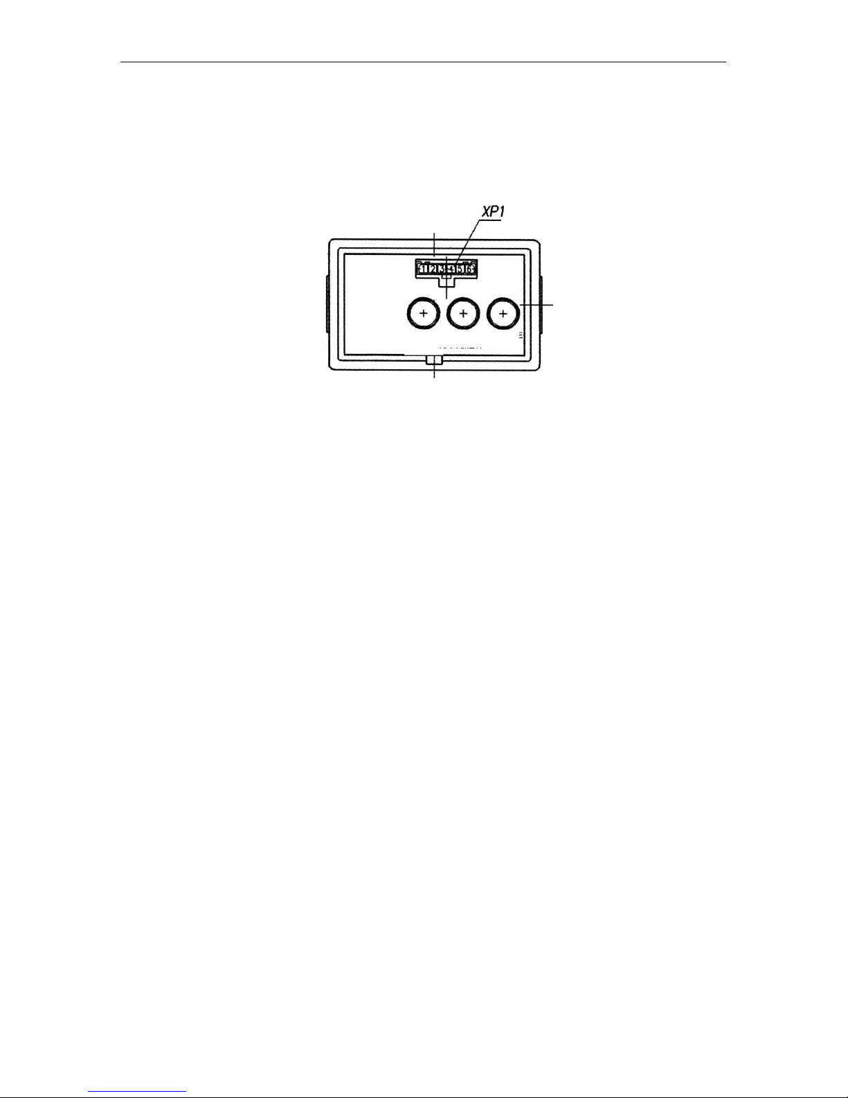
Controls and Instrumentation
MTZ series 900
16
HG5 is the indicator of switching on the upper beam of the road headlights; it lights up
when the upper beam of the road headlights is ON.
Note! The indicators light up and go out synchronously with the changes in the states of
the system sensors.
Indicator control board
The programming board makes it possible to perform the manual programming of
the combined indicator by means of the “Parameter” (Параметр) and “Value” (Значение)
buttons and to modify the mode of display of the parameters to be shown on the LCD.
The diagnostic connector ХР1 located on the front panel of the control board
makes it possible to perform the automatic programming (reprogramming) of the CI by
means of a special instrument (if provided). Should such an instrument be unavailable,
the programming shall be performed by means of the above buttons.
1.10. CI programming procedure
1. On selecting the fixed value of the programming parameter:
1.1. On pressing the “Parameter” (Параметр) button for the first time, the LCD is
switched to the mode of viewing the parameter to be programmed and its numerical value. On pressing this button repeatedly, the parameters are switched over cyclically.
1.2. On pressing successively the “Parameter” (Параметр) button, the numerical value of
the set parameter to be programmed changes.
1.3. The mode is exited automatically if neither “Parameter” (Параметр) nor “Value”
(Значение) button has been pressed within 7.0 sec.
On exiting the mode, the last values of the parameters selected by the “Value”
(Значение) button are saved.
2. When entering the unfixed value of the programming parameter:
2.1. Select the parameter, the values of which shall be set, by means of the “Parameter”
(Параметр) button;
2.2. Press twice the “Mode” (Режим) button; the least digit of the numerical value starts
blinking;
2.3. To change the value of the blinking digit of the parameter, use the “Value”
(Значение) button;
2.4. To go to the more significant digit, press the “Parameter” (Параметр) button;
2.5. To exit the mode of programming an unfixed value of any parameter, press twice the
“Mode” (Режим) button;
2.6. On exiting the above mode, the digits of the entered value of the parameter become
lit steadily;
2.7. The newly entered value is set the last in the list of the parameter values allowed to
be programmed;
MODE VALUE
PARAMETER
Page 48
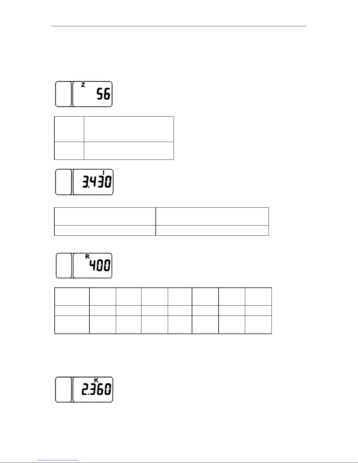
Controls and Instrumentation
MTZ series 900
17
Entering the parameters to be programmed:
1. To display correctly the tractor motion speed, it is necessary to program in the specified order the following parameters:
Parameter “Z” is the number of teeth of the pinions of the final shafts of the driving
wheels (right and left), over which the (rotational) speed sensors are installed;
Select from the Table:
Number
of teeth
(Z)
Tractor make
69
MTZ 590; 80.1; 890; 900;
922; 950
Parameter “I” is the multiplying factor of the gear rate of the wheel reduction gear;
Select from the Table
Gear ratio of the wheel reduction
gear (I)
Tractor make
1.000
MTZ 590; 80.1; 890; 900; 922; 950
Parameter “R”
R is the rear wheel rolling radius (mm);
Select from the Table
Tyre mark
16,9R30
18,4L30
15,5R38
9,5-42
18,4R34
(Ф-11)
16,9R38
18,4R38
Rk, m
0.698
0.720
0.755
0.730
0.770
0.800
0.830
Number
coded
700
720
755
730
770
800
830
2. To display correctly the engine rotational speed, it is necessary to program in the specified order the gear ratio of the alternator drive (parameter “K”) from Table 8-6:
Page 49
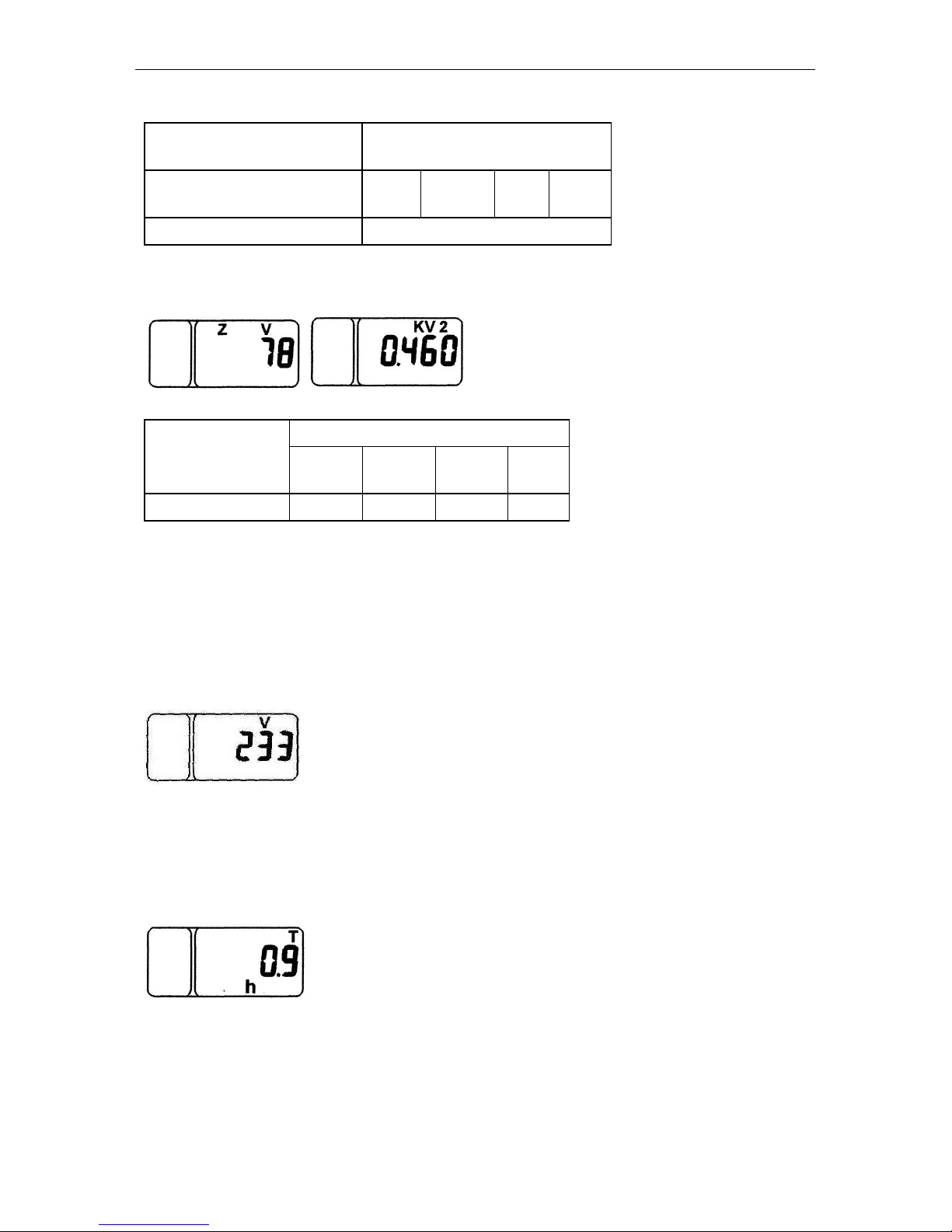
Controls and Instrumentation
MTZ series 900
18
Select from the Table
Gear ratio of the alternator
drive (К2)
Engine mark
2.36
Д-242
Д-243
Д-245
Д-
245.5
2.41
D-260
3. To display correctly the PTO’s rotational speeds (540 and 1000), it is necessary to
program the gear ratio PTO “КV2” and the number of teeth of the pinion at the place of
installation of the PTO sensor “ZV” in the specified order:
Select from the Table
Gear ratio of the
PTO drive
Engine mark
Д-242
Д-243
Д-245
Д-
245.5
(КV2)
0.60
0.46
0.46
0.60
- in the absence of the PTO rotational speed sensor (the signal from the phase winding of
the alternator serves as a signal for indication of the PTO rotational speed) the value of
the parameter “ZV” to be entered shall be equal to 0.
- in the absence of the PTO rotational speed sensor (the signal from the phase winding of
the alternator serves as a signal for indication of the PTO rotational speed) the value of
the parameter “ZV” to be entered shall be equal to 0.
4. To display correctly the residue of fuel in the tank (if the FFRS sensor is installed), it is
necessary to program the fuel tank volume “V” in the specified order:
For tractors with plastic fuel tank, set the value of 140 litres.
Also, when pressing the “Parameter” (Параметр) button in the programming mode, the
list of programmable parameters displays the independent parameter of the adjusted
content of the counter of the astronomic time of running the engine. This parameter is
unavailable for measurement; it presents the precise (to 1/10 hours) value of the number
of hours of the engine running.
On switching on the backlight of the instrument scales (the main light switch (MLS)
is set to the positions II “The backlight of the instrument dash and clearance lights are
ON” and III “The consumers of the position II and front road headlights and clearance
lights are ON”), the brightness of the PTO indicator segments and LCD is automatically
reduced.
Page 50
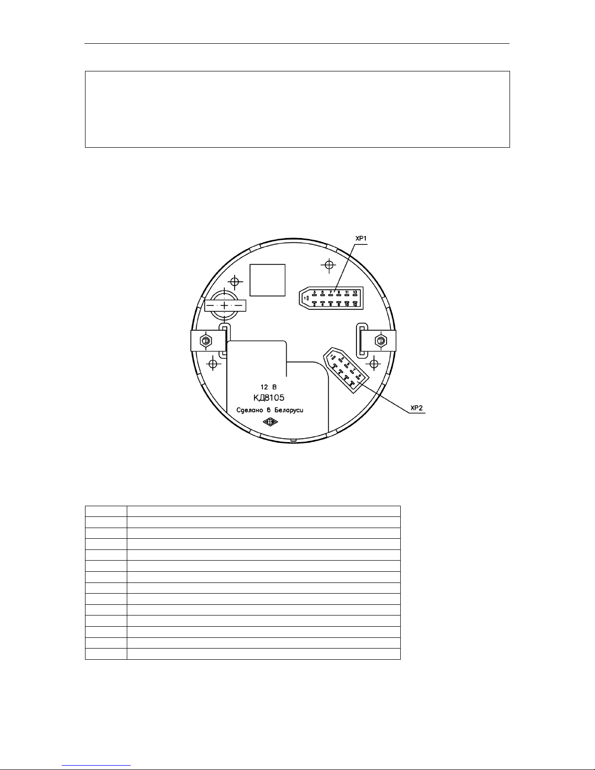
Controls and Instrumentation
MTZ series 900
19
IMPORTANT! Each time the power supply of the CI is switched ON, the functioning
of the pointer indicators and PTO indicator scale elements is tested. Within one second after this, the indicator pointers deviate from the initial marks beyond the following first marks of the scales (beyond “5” for the motion speed and beyond “10” for the
rotational speed), and all the segments and designations “540” and “1000” of the
PTO scale are switched on.
1.11. Connecting the tachospeedometer
To connect the tachospeedometer to the instrumentation system, a 13-contact block
(ХР1) and a 9-contact block (ХР2) are provided on the rear panel of the instrument (Fig.
5).
Fig. 5
The identification of the pins of the blocks is given в Tables (11) and (12).
Table 11
Contact
Address of the XP1 connector pin
1
To the terminal “–“ (common)
2
To the power supply unit “+12 V”
3
To the rotational speed sensor “PTO”
4
To the rotational speed sensor “Left wheel”
5
6
To the rotational speed sensor “Right wheel”
7 8
To the phase winding of the alternator
9
To the switch of the backlight
10
To the switch of the headlight upper beam
11
To the switch of the trailer turn indicators
12
To the switch of the parking brake
13
To the switch of the tractor turn indicators
Page 51
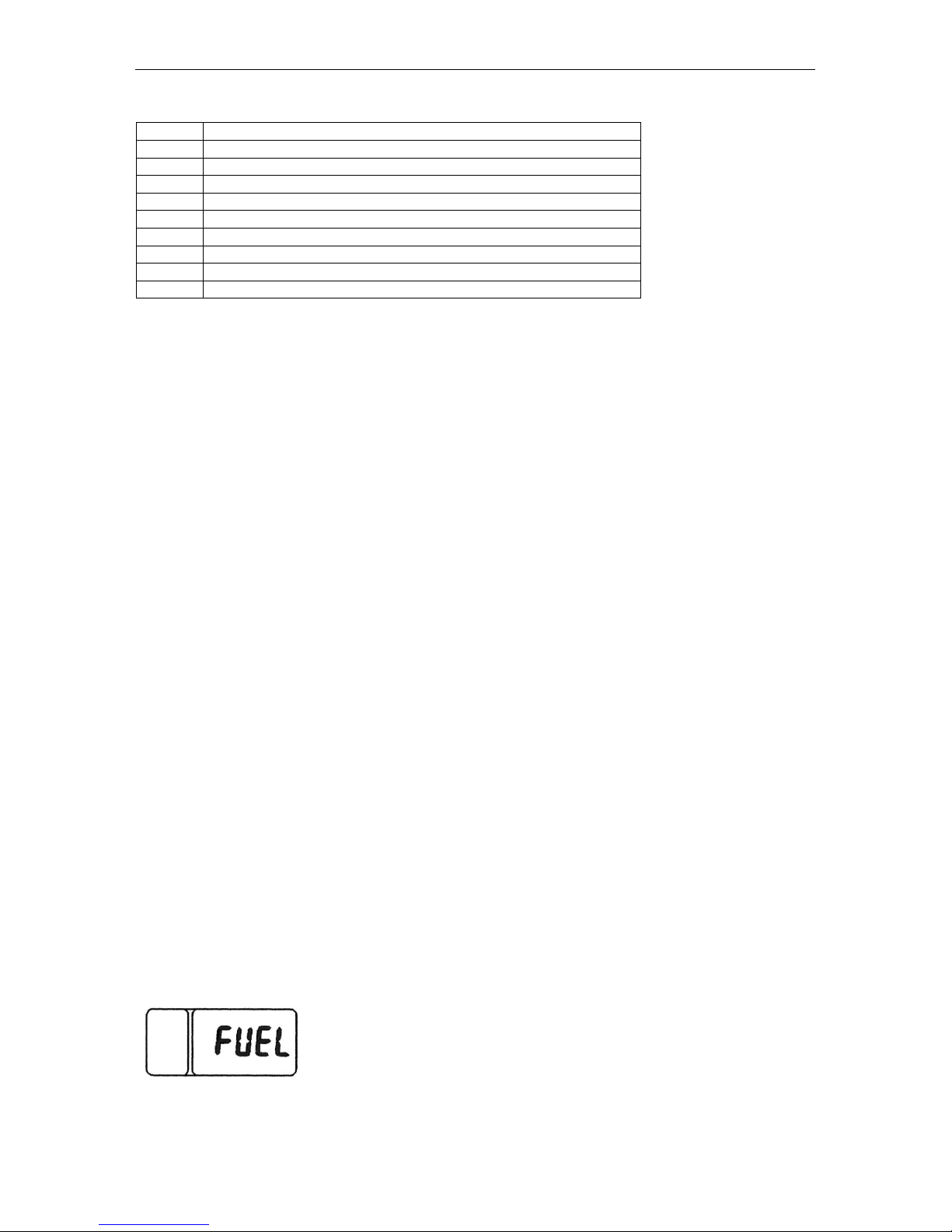
Controls and Instrumentation
MTZ series 900
20
Table 12
Contact
Address of the XP2 connector pin
1
To the terminal “–“ (common)
2
To the control board contact “Indication Mode”
3
To the control board contact “Parameter Selection”
4
To the control board contact “Parameter Value”
5 6 7
To the fuel volume sensor
8
To the control board contact “M”
9
To the control board contact “+UBZ”
1.12. Indicator Diagnostics and Troubleshooting
1. No instrument backlight:
Check the power supply voltage at the pin “9” of the 13-contact of the contact block (ХР1)
of the instrument (Fig. 5);
2. Jerking and jumps of the pointer of the engine rotational speed indicator over
the dial: poor contact on the alternator terminal and, therefore, poor signal from the
phase winding of the alternator. Repair.
3. Jerking of the pointer and understating the reading of the engine rotational
speed:
- Check and adjust the tension of the alternator driving belt.
4. Over- or understated readings of the engine and PTO’s rotational speeds (with
the normal movement of the pointer):
- Check the correctness of programming the instrument according to the gear ratio of the
alternator drive (parameter “K”): (see item 1.10);
5. The counter of astronomical hours of the engine running fails to accumulate the
operating time:
- Check the connection of the wire to the contact «8» of the instrument block (ХР1) and
the presence of the frequency signal from the phase winding of the alternator.
6. Over- or understated readings of the tractor speed:
1. Check the correctness of the instrument programming according to the rolling radius of
the rear wheels (R) (see item 1.10);
2. Check the correctness of the programming according to the number of teeth of the
half-axle pinion (Z) (see item 1.10).
3. Check the correctness of programming the multiplying factor of the gear rate of the
wheel reduction gear (I) (see item 1.10).
7. The “FUEL” reading appears on the indicator display
Check the connection and serviceability of the frequency fuel volume sensor (FFVS) to
the contact “7” of the block (ХР2).
Page 52
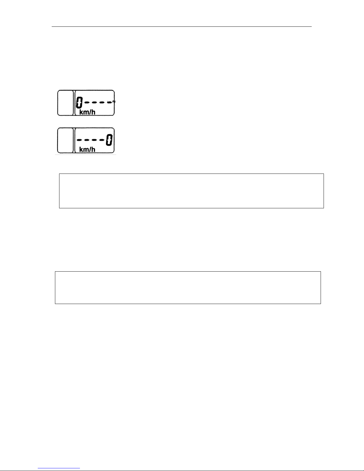
Controls and Instrumentation
MTZ series 900
21
8. No readings of the tractor motion speed:
- Check the presence of the signals from the both speed sensors (BV1, BV2).
9. The “0km/h----” or “----0кm/h” readings appear on the indicator display within 1012 s after starting the motion of the tractor:
- no signal from the left speed sensor (BV2) check the serviceability of the sensor.
- no signal from the right speed sensor (BV1) check the serviceability of the sensor.
ATTENTION! The speed readings are affected considerably by the speed sensor setting and adjustment performed when replacing or repairing the speed sensor. The gap
“S” between the end face of the sensor (2), Fig. …, and projection of the tooth of the final pinion (6) of the rear axle shall be as specified in Table … below
A brief message about faults (Example: 0----, FUEL) is shown according to the
priority on the LCD regardless the information displayed. On pressing successively the
“Mode” (Режим) button, the messages shall be paged. When viewing the last message
and pressing repeatedly the “Mode” button, the LED is switched to the mode of displaying over the cycle of the operating parameters specified below. The faults are displayed
on the LCD each time the instrument is switched on until the fault is eliminated.
Note:
- On switching on the power supply of the CI, the LED shows the information in the indication mode selected until the power supply of the CI is switched off in case of absence of the messages about faults.
Page 53
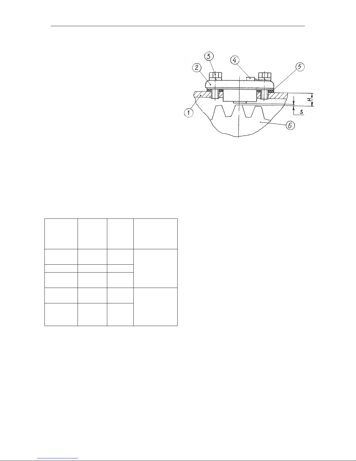
Controls and Instrumentation
MTZ series 900
22
1.13. Setting and Adjustment of the speed
sensors (BV1, BV2) (Fig. 6)
The speed sensors (2) are fastened by means
of the bolts (3) to the cover of the rear axle
housing (1) in the zone of the left and right final pinions (6) of the final drives.
The gap “S” between the end face of the sensor and projection of the tooth of the final pinion shall be adjusted by means of the spacers
(5) as follows:
1. Measure the dimension “Н” from the sur-
face of the cover (1) to the tooth projection;
2. Select and place the necessary number
of spacers for setting the gap “S” corre-
sponding to the measured value “Н”
(see Table 13);
Install the ground wire (4) and tighten the bolts
(3).
Table 13
Н,
mm
Number
of
spacers
(Pos. 5)
S,
mm
Note
11.25-12
4
1.05-
1.6
When using
the cover (1)
with the
thickness
S=6 mm
12.1-13
3
0.8-1.8
13.1-
13.73
2
0.9-
1.53
13.25-14
2
1.05-
1.8
When using
the cover (1)
with the
thickness
S=8 mm
14.1-
15.73
1
0.9-
2.53
Fig. 6. Setting the speed sensors:
1 – cover of the rear axle cover;
2 – speed sensor (BV1, BV2);
3 – bolt;
4 – ground wire;
5 – adjusting spacers;
6 – final pinion.
Page 54
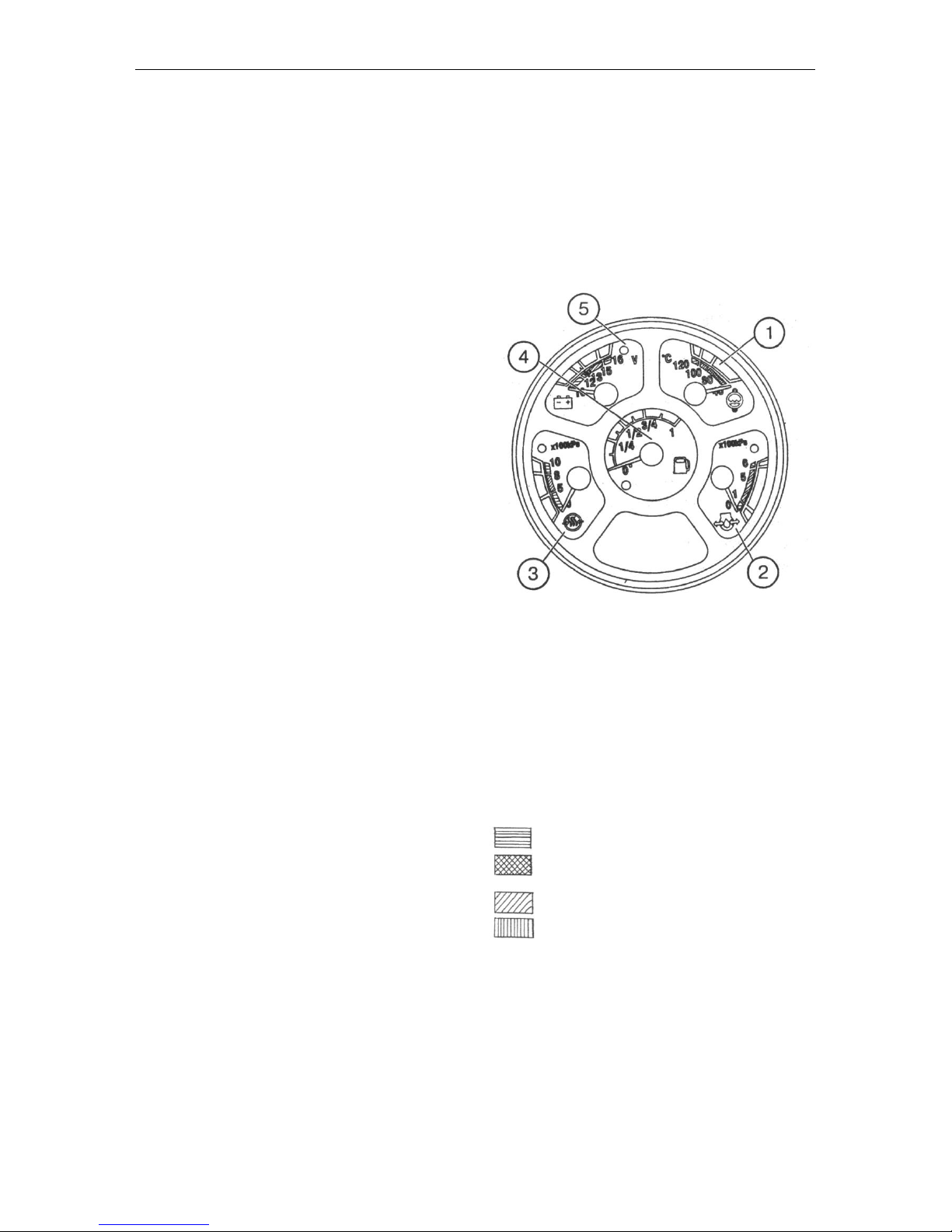
Controls and Instrumentation
MTZ series 900
23
1.14. Combination meter (Fig. 7)
The combination meter includes the five
gauges (1, 2, 3, 4, 5) monitoring the various
parameters of the tractor. All the gauges are
provided with emergency control lamps. The
gauges (1, 2, 3, 5) have the red control lamps,
and the indicator (4) – the yellow control lamp.
To switch on the combination meter, turn the
key of the starter and instrumentation switch
(SA6) to the “I” position. In this case, the
pointer of the oil pressure indicator (2) and
temperature indicator (1) shall move to the zero marks of the scale and the pointers of the
air pressure indicator (3), fuel level indicator
(4) and voltage indicator (5) shall be set to the
positions corresponding to the actual positions
of the parameter monitored.
The electrical circuit of the instruments is protected by the fuse “2” in the unit (F2).
Engine cooling fluid temperature indicator
(1) with the emergency temperature control
lamp (red). It operates with the temperature
sensor (BK1). The indicator scale has three
zones:
– operating – 80…100°C – green;
– non-operating – 40…80°C – yellow;
100…120°C – red.
Engine oil pressure indicator (2)
with emergency pressure drop control lamp
(red). It operates with the pressure sensor
(BP1).
The indicator scale has three zones:
– operating – 100…500 kPa – green;
– non-operating – 0…100 kPa and
500…600 kPa – red.
When starting the cold engine, the pressure of
up to 600 kPa is possible.
Indicator of the air pressure in the pneumatic
system (3) with the red emergency pressure
control lamp. It operates with the air pressure
sensor (ВР2).
The indicator scale has three zones:
- operating – 500…800 kPa – green;
- non-operating – 0…500 kPa and
800…1000 kPa – red.
Fig. 7. Combination meter:
1 – engine cooling fluid temperature indicator;
2 – indicator of the engine oil pressure;
3 – indicator of the air pressure in the pneu-
matic system;
4 – indicator of the fuel level in the tank;
5 – indicator of voltage of the storage battery
or alternator.
Scale zones marked by hatching:
– red
– yellow
– green
– orange
Page 55
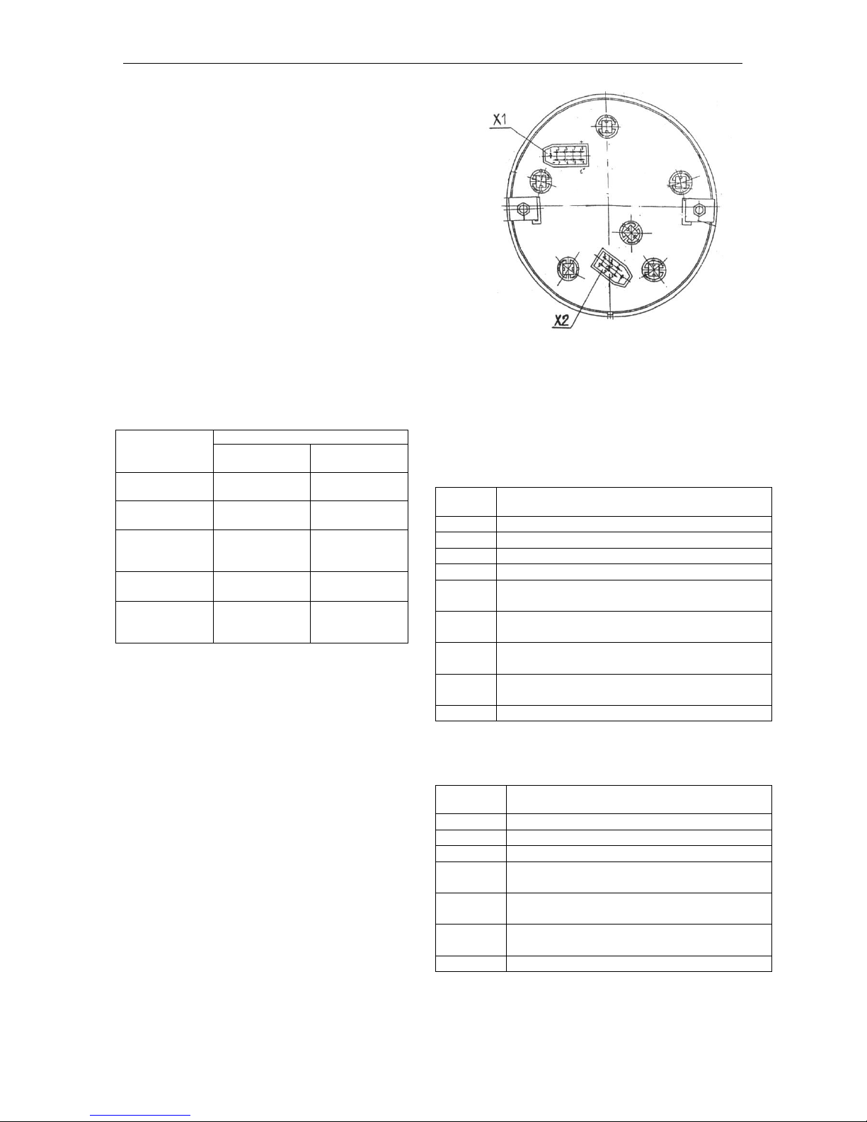
Controls and Instrumentation
MTZ series 900
24
Indicator of the fuel level in the tank (4)
with orange control lamp of reserve level. It operates with the fuel level sensor (BN1).
The instrument has the points: 0-1/4-1/2-3/4-
1.
Do not allow consuming the fuel to empty
tank (instrument pointer is at orange zone).
Voltage indicator (5) with the red control
lamp red of additional SB charging.
It displays the SB voltage, when the engine
is running and the starter switch key is in the
“I” position. When the engine is running, it
indicates the voltage at the generator terminals.
The reading values are given in Table 14 below.
Table 14
Scale zone, col-
our
Power supply system state
when the engine
is running
when the engine
is not running
13.0 – 15.0 V
green
Normal charging mode
10.0 – 12.0 V
red
Generator is
not working
SB is run down
12.0 – 13.0 V
yellow
No charging of
SB (low charging voltage)
SB has
normal
charging
15.0 – 16.0 V
red
SB overcharging
SB has normal
charging
White hairline in
yellow zone
The rated emf
of the SB is12.7
V
1.15. Connection the combination meter
To integrate the combination meter to the instrumentation system, the rear panel is provided with two blocks Х1 and Х2 (Fig. 8).
The purpose of the contacts of the blocks of
the combination meter is shown in Tables
15, 16.
Fig. 8. Blocks for connecting the combination meter (rear
view):
Х1 – 9-contact block;
Х2 – 7-contact block.
Block Х 1
Table 15
Contact
Address
1
To the instrument backlight switch
2
To the “–” terminal of the battery
3
Monitoring the storage battery charging
4
Buzzer
5
To the sensor of the oil pressure in the engine (ВР1)
6
To the sensor of the emergency temperature of the engine cooling fluid (SК1)
7
To the sensor of the emergency oil pressure
in the engine (SP2)
8
To the sensor of the cooling fluid temperature (BK1)
9
To the “+” SB terminal (12 V)
Block Х2
Table 16
Contact
Address
1
Reserved
2
Reserved
3
To the fuel level sensor (BN1)
4
To the gearbox oil pressure sensor (not
used)
5
To the sensor of emergency drop of the
air pressure (SP4)
6
To the sensor of the reserve fuel level
(BN1)
7
To the sensor of the air pressure (ВР2)
Page 56
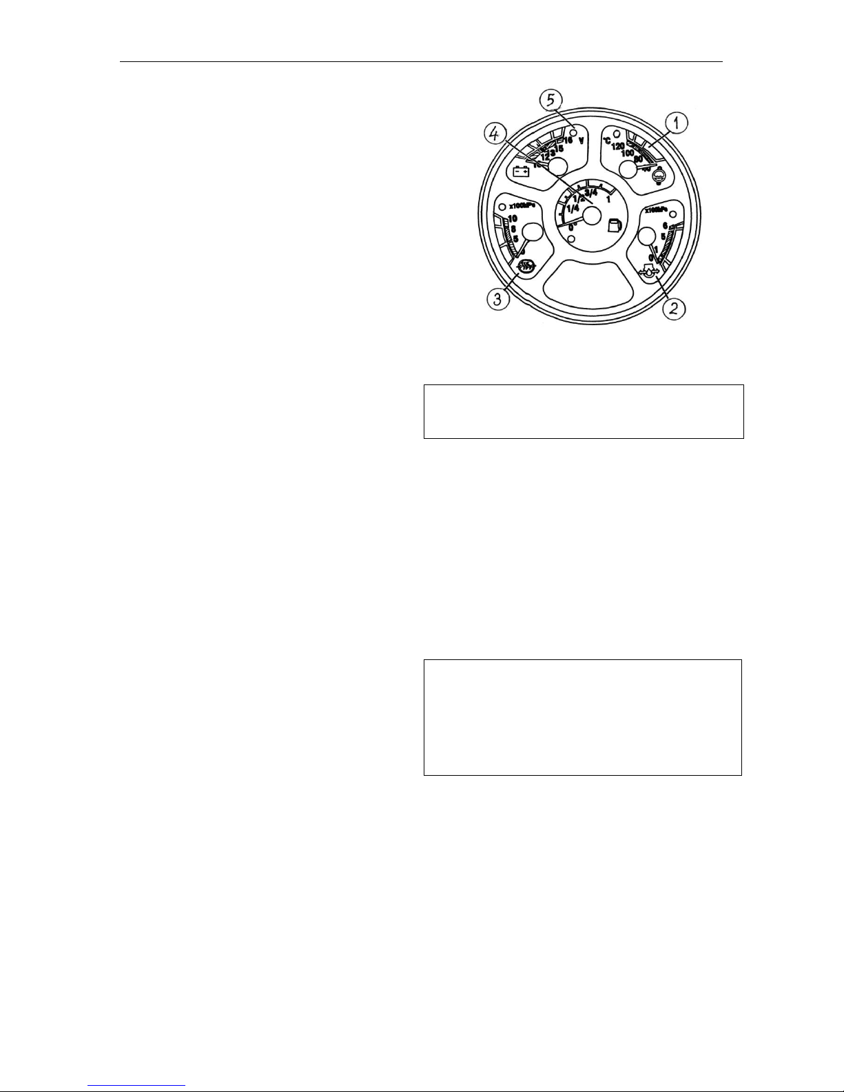
Controls and Instrumentation
MTZ series 900
25
1.16. Combination Meter Diagnostics and
Troubleshooting
1. No backlight of the instrument scales
on setting the SA10 central light switch:
1. Check the presence of the power supply
voltage at the terminal “1” of the block “Х1”
(to the instrument backlight switch) and at
the terminal “9” (to the power supply unit “+
12 V”).
In case of absence of the voltage, eliminate
the open circuit. If the voltage is present:
2. Check the intactness of the backlight
lamps and replace them, if necessary.
2. The temperature indicator (1), Fig. 9,
operated jointly with the thermistor-type
temperature sensor BK1 (ДУТЖ-02М, resistance range: 243…22.5 Ω).
2.1. The temperature indicator pointer
goes off-scale:
1. Breakage of the wire to the terminal “9” of
the block “Х1” (“+” 12 V of the SB);
2. Breakage of the wire to the terminal “2” of
the block “Х1” (“–” of the power supply);
3. If there is no breakage, the temperature
indicator is faulty.
2.2. The pointer of the temperature indicator is set before the initial point of the
scale:
1. Breakage of the wire to the terminal “9” of
the block “Х1” (“+” 12 V of the SB);
2. Breakage of the wire to the terminal “8” of
the block “Х1 ” (to the temperature indicator
BK1);
3. Fault of the temperature sensor;
4. Fault of the temperature indicator.
3. Indicators of the oil pressure in the engine (2) and air pressure in the pneumatic
system (3). They operate from the following sensors:
Rheostat-type oil pressure (ВР1) (ДД-6М;
10…184 Ω) and rheostat-type oil pressure
(ВР2) (ДД-10-01М).
3.1. The indicator pointer is set before the
initial point of the scale:
1. Breakage of the wire to the terminal “2” of
the block “Х1” (“–” of the power supply);
2. Breakage of the wire to the terminal “9” of
the block “Х1” (“+” of the power supply);
3. If there is no breakage, the pressure indicator is faulty.
Fig. 9.
IMPORTANT! To avoid errors in the temperature indication, use the ДУТЖ – 02М
temperature sensors mentioned above.
3.2. The indicator pointer goes off-scale:
1. Breakage of the wires to the terminals “4”,
“5”, “7” of the block «Х1» or short circuit inside
the indicator;
2. The pressure indicator is faulty.
4. Fuel level indicator (4).
It operates with the float-type rheostat sensor
(BN1) installed in the fuel tank (ДУМП-21М
(320…0 Ω)).
NOTE! Should there be no fuel in the tank
when switching on the indicator; the indicator pointer shall be at the initial point of the
scale. If the indicator is switched off or there
is a wire breakage, the indicator pointer
shall go off-scale.
4.1. The indicator pointer is before the initial
point of the scale:
1. Breakage of the wire to the terminal “9” of
the block “Х1” (to the terminal “+12V”);
2. Breakage of the wire to the terminal “3” of
the block “Х2” (to the fuel level sensor);
3. The fuel level sensor is faulty;
if there is no breakage and the sensor is in
good repair, replace the combination meter
Page 57
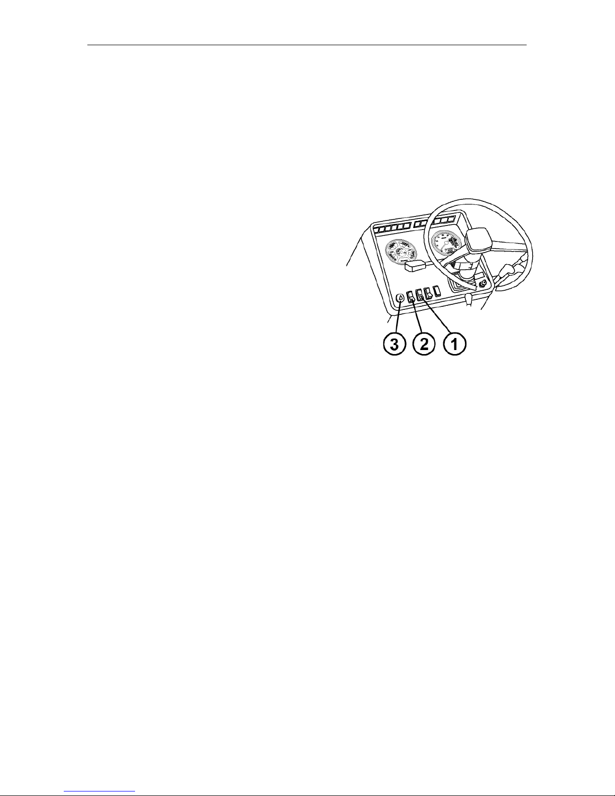
Controls and Instrumentation
MTZ series 900
26
or repair the fuel level indicator.
4.2. The indicator pointer goes off-scale:
1. Breakage of the wire to the terminal «2»
of the block “Х 1 ” (output “–“ of the power
supply);
2. If there is no breakage, the fuel level indicator is faulty. Repair the indicator or replace
the combination meter.
Front windscreen washer switch (1)
Pressing the button (1) switches the
windscreen washer on.
Three-position light switch (2)
The button (2) has three positions:
• “OFF”;
• “Dashboard lighting, clearance lights
and number plate light ON” ;
• “All control lamps units including the
front headlights ON” .
Fault signalling switch (3)
Pressing the button (3) switches the
fault signalling on. There is a control
lamp inside the button, which blinks
simultaneously with the flashing light
signalling.
Page 58
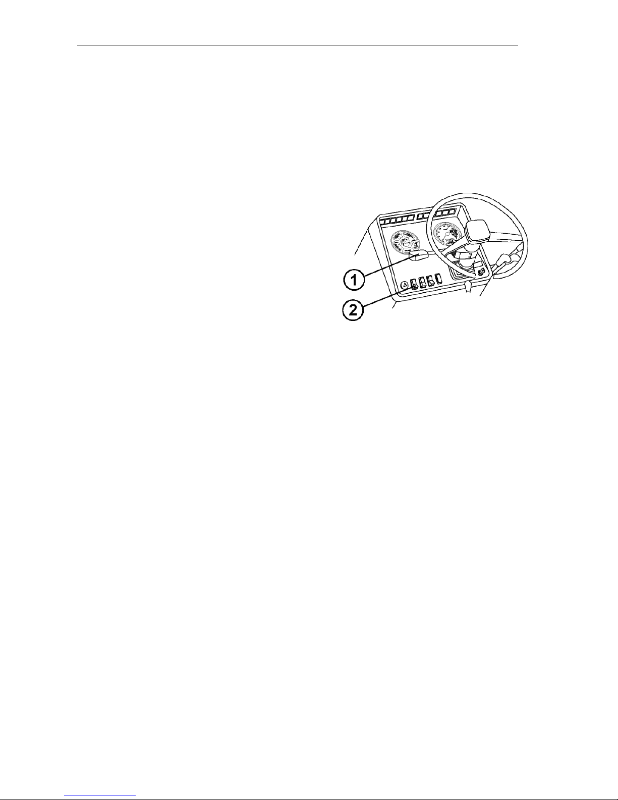
Controls and Instrumentation
MTZ series 900
27
Steering-Wheel-Mounted (Multifunction)
switch (1)
It ensures the switching-on of the turn
indicators, toggling the beam of the road
headlights (lower/upper beam), warning by
upper beam warning and horn beep.
Turn indicator
Turning the arm (1) up or down switches
on the right or left turning indicator, respectively.
NOTE: After completing the turn of the
tractor, the arm (1) is returned automatically to the neutral position.
Upper/lower beam
When the road headlights are switched on
by the switch (2), pushing the arm (1)
switches the “upper beam” o n and pulling
the same switches the “lower beam” on.
Pulling the arm (1) further from the “lower
beam” position towards the operator up to
the stop switches on shortly the upper
beam (no n -fixed position) .
Horn beep
Pressing the arm (1) in axial direction
switches the beep on.
Page 59
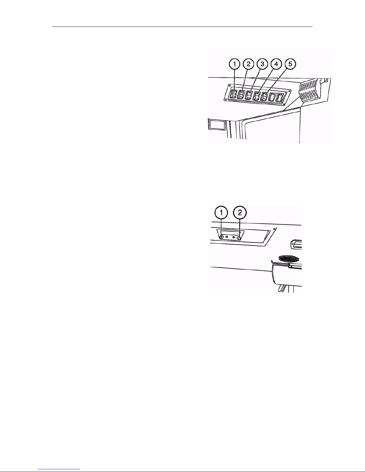
Controls and Instrumentation
MTZ series 900
28
Front windscreen wiper switch (1)
Pressing the button (1) switches front
windscreen wiper on.
The switch has three positions:
• OFF;
• Low speed ON;
• High speed ON.
NOTE: In the “OFF” position wind-
screen wiper automatically returns to
initial position
Cab heater and fan switch (2)
Pressing the button (2) switches the cab
air ventilation on.
The switch has 3 positions:
• “OFF”;
• “Low air supply mode ON”;
• “High air supply mode ON”.
Rear working lights switch (3)
Pressing the button (3) switches the rear
working lights on or off. The lights being
on, the button (3) is illuminated with a
built-in backlight lamp.
Front working lights switch (4)
Pressing the button (4) switches the
front working lights on or off. The lights
being on, the button (4) is illuminated
with a built-in backlight lamp.
Road-train sign lighting switch (5)
On pressing the button (5), the three orange lights on the roof forepart are
switched on and the button is backlit.
Radio receiver switch
(if installed)
1 – On (Off) and volume control;
2 – Tuning.
NOTE: The radio receiver operates
only in starter key positions I or III
only.
Page 60
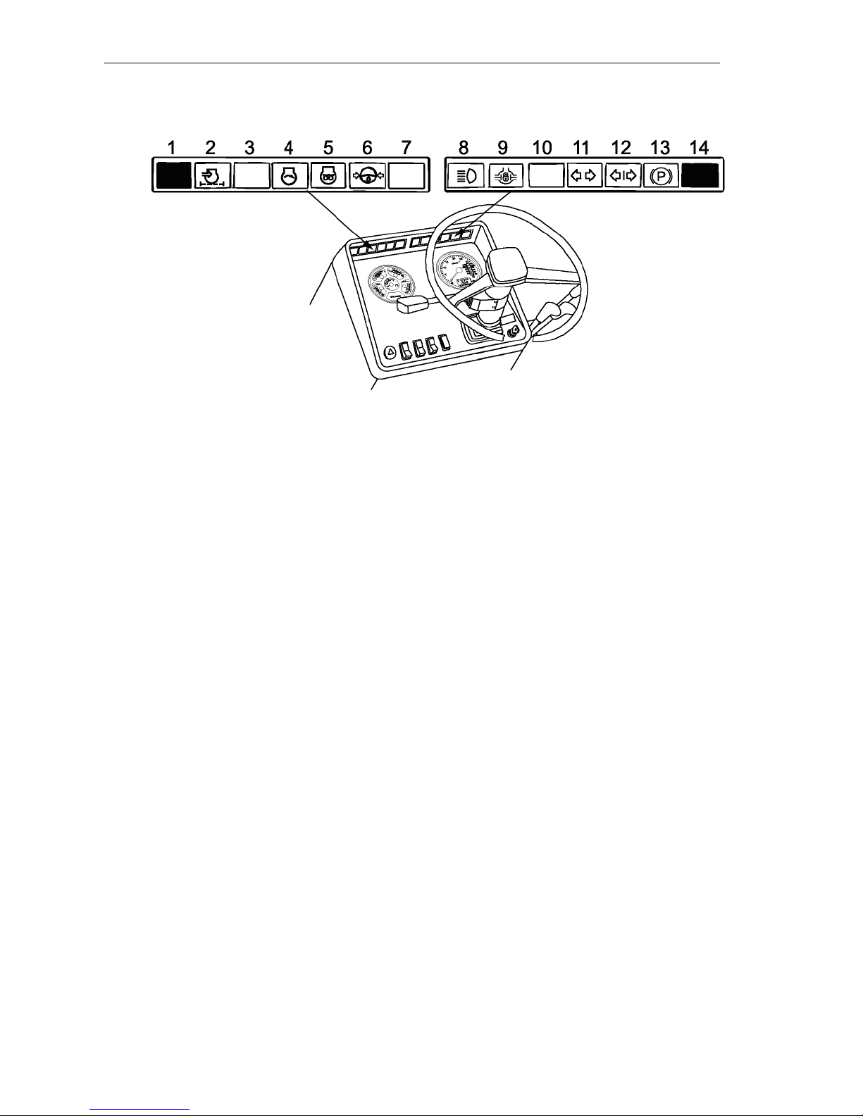
Controls and Instrumentation
MTZ series 900
29
Control lamps of the dashboard (dashboard 80-3805010-Д 1 )
1 and 14 – Buttons for testing the ser-
viceability of the control lamps unit. On
pressing the button, all the lamps shall
be lit.
2 – Air filter blocking. The control lamp
(orange) lights up when the maximum
allowed level of filter blocking is exceeded and it needs cleaning.
3 – Reserved.
4 – Engine start lamp: This orange con-
trol lamp lights up on turning the starter
switch key to position II to indicate that
the starting system functions properly. If
the lamp blinks at the frequency of 1.5
Hz, the gearbox control lever is not in
neutral position or the engine starting
locking switch circuit is out of order. If
the lamp blinks at the frequency of 3.0
Hz, there is a failure in the alternator
phase winding circuit. Eliminate the fault
and restart.
5 – Starting aid lamp: This orange control lamp is on when pressing the button of electric torch pre-heater (ETP).
After 30 s the lamp will start blinking,
indicating that diesel engine starting
system under cold conditions is ready
for operation.
6 – HPS emergency oil pressure. The
lamp (red) lights up when oil pressure in
HPS feeding system is below the allowable level.
7 – Reserved.
8 – Upper beam indicator: Blue control
lamp lights up when switching on the
upper beam of the front headlights.
9 – Rear axle differential locking control
lamp. The lamp (green) is on when
switching automatic differential locking
(ADL).
10 – Reserved.
11 – Tractor turn indicator (green).
12 – Trailer turn indicator (green).
13 – Parking brake indicator (red).
Page 61
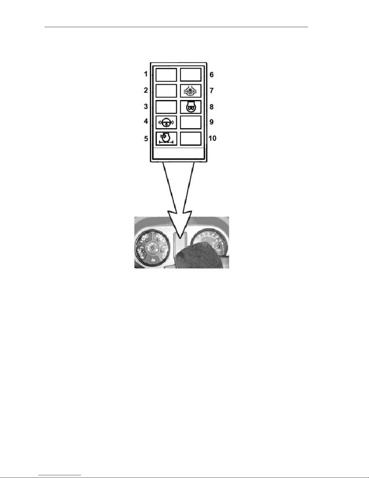
Controls and Instrumentation
MTZ series 900
30
Control lamps of the dashboard (dashboard 826-3805010)
1 – Reserved indicator (green)
2 – Reserved indicator (green)
3 – Reserved indicator (red)
4 – HPS emergency oil pressure. The
lamp (red) lights up when oil pressure in
HPS feeding system is below the allowable level.
5 – Air filter blocking. The control lamp
(orange) lights up when the maximum
allowed level of filter blocking is exceeded and it needs cleaning.
6 – Reserved indicator (blue).
7 – Rear axle differential locking control
lamp. The lamp (green) is on when
switching automatic differential locking
(ADL).
8 – Starting aid lamp: This orange control lamp is on when pressing the button of electric torch pre-heater (ETP).
After 30 s the lamp will start blinking,
indicating that diesel engine starting
system under cold conditions is ready
for operation.
9 – Reserved indicator (red).
10 – Reserved indicator (red).
Page 62
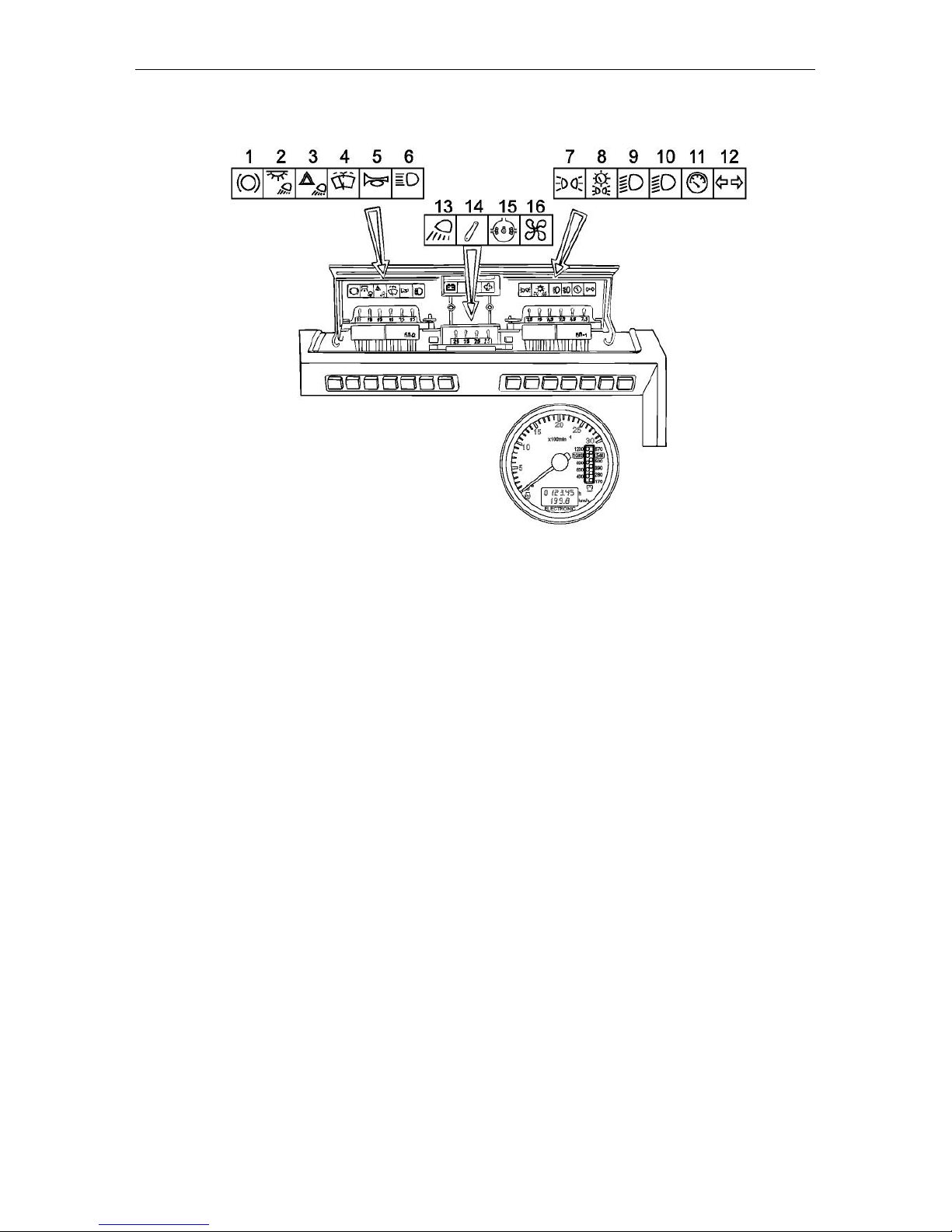
Controls and Instrumentation
MTZ series 900
31
Fuses
Three electric circuit fuse boxes are installed in the dashboard. To get access
to the fuses, remove the screw on the
dashboard cover and open it.
The fuses protect the following electric
circuits of the tractor against overloads:
1 – Braking signal (15 A);
2 – Cab light and rear working lights ( 1 5
A) ;
3 – Fault signalling (15 A);
4 – Windscreen wiper and washer (15
A);
5 – Horn (7.5 A);
6 – Upper beam of the road headlights
(15 A);
7 – Left clearance lights (7.5 A);
8 – Right clearance lights and backlights
of the dashboard and registration plate
(15 A);
9 – Lower beam of the left road head-
light (7.5 A);
10 – Lower beam of the right road head-
light (7.5 A);
11 – Instrumentation, control lamps
block, parking brake indicator (7.5
A);
12 – Turn indicator relay (7.5 A) ;
13 – Front working lights (25 A);
14 – HMS supply (25 A);
15 – Side board supply (PTO, DL) (15
A);
16 – Heating system fan (25 A).
The storage battery charging circuit is
protected with the fuse rated at 60 A.
WARNING! To prevent the electric wiring from burning, never apply fuses of
higher current rating than specified
above. If the fuse blows often, detect
the reason and eliminate it.
Page 63

Controls and Instrumentation
MTZ series 900
32
In case of blowing of the fuse due to a short circuit, proceed as follows:
1. Connect the wires from the pilot lamp to the terminals of the fuse box at the place of
the fuse blown.
a) If there is a short circuit, the lamp will be lit with incandescence,
b) If the circuit and consumer are intact, the lamp will not be lit or will be lit dimly.
2. Connect the circuit from the fuse to the consumer and ensure that the lamp is not
lit or is lit dimly (in the presence of a switched on consumer in the circuit);
3. Fit a new fuse.
During the operation, the contact resistance between the fuse and its holders can increase due to oxidization.
It results in increase of the voltage drop in the circuit and heating causing the circuit failure. The defect is detected by the disturbance of the operation of the consumer (reduction of the power) and heating of the fuse. Eliminate the defect by cleaning the holder
and fuse from the oxide film.
Page 64
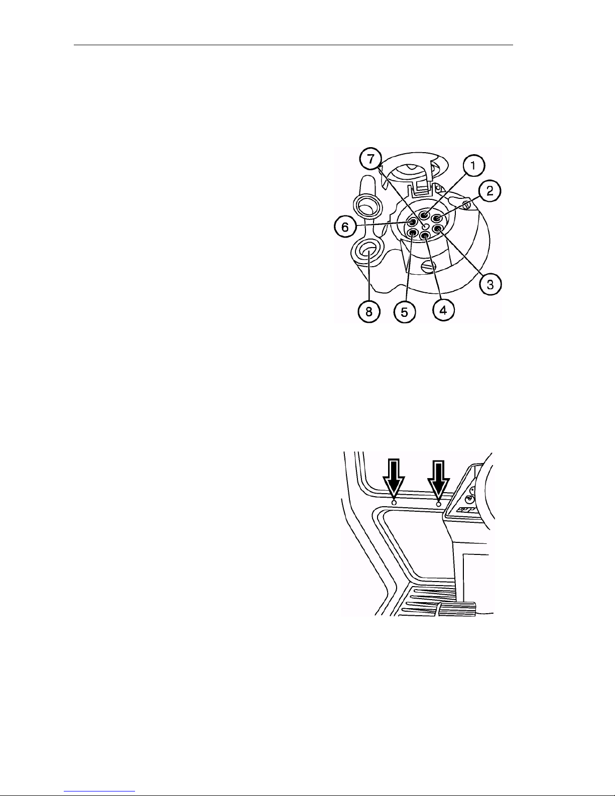
Controls and Instrumentation
MTZ series 900
33
Electric equipment connector
components
A standard 8-pin socket is designed for
connecting the current-consuming units
of a transport machine or trailed agricultural implement. It is installed on the
cab’s rear support. A plug of the wire
bundle of the hitched machines is connected to the socket.
Socket connection terminal marking:
1 – Turn indicator, left;
2 – Horn;
3 – “Ground”;
4 – Turn indicator, right;
5 – Right clearance light;
6 – Stop light;
7 – Left clearance light;
8 – Hand lamp connection.
Installing the monitor on the tractor
An electronic monitor can be installed on
the cab front wall. There are two openings on the front wall between the front
and the lower glasses to the left and right
from the dashboard.
Page 65
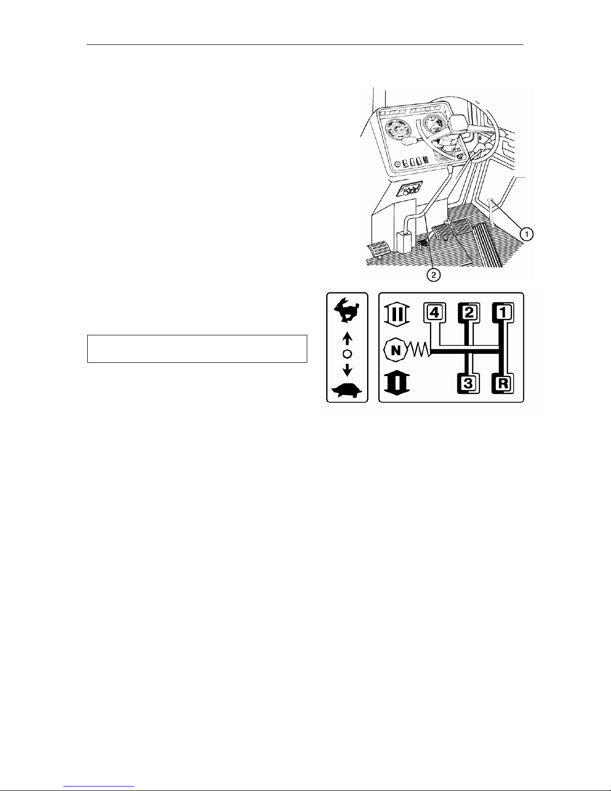
Controls and Instrumentation
MTZ series 900
34
Gearbox single-lever control
The 7F/2R synchronized gearbox combined
with synchronized reduction gear allows ob taining 14 forward and 4 reverse gears.
The gears are shifted by means of the lever (1) in
accordance with the shifting pattern. Prior to put ting in the gear, select the required range (stage) .
IMPORTANT! The ranges are selected and the
gears are shifted by means of a single lever
(1), the range (either I or II) being selected
first.
The reduction gear lever (2) shall be always in
the engaged: either forward (direct trans-
mission “H”) or reverse (retarded trans -
mission “L”).
NOTE: The lever of the reduction gear or
multiplier has no fixed neutral position. The
lever is allowed to be set to the neutral posi tion when starting the engine in cold season only.
Multiplier lever (2) has two positions:
- “L” - direct gear (OFF) – foremost po -
sition;
- “Н” step-up gear (ON).
ATTENTION: using the gear “R” in traction
mode is not allowed.
Page 66
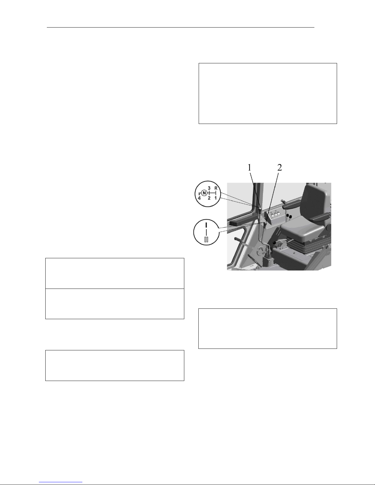
Controls and Instrumentation
MTZ series 900
35
Gearbox two-lever control
The 7F/2R mechanical two-range fixedratio transmission gearbox with two-lever
control (gears are shifted and the ranges
are selected by means of separate levers).
Jointly with the synchronized accelerator,
the gearbox allows obtaining 14 forward
and 4 reverse gears.
Selecting the ranges and shifting the
gears
The gears are shifted and the ranges are selected by means of separate levers according to the patterns shown in Fig.
Select the required speed of the
tractor motion according to the information
plate on the right side glass of the cab.
To put in the gear corresponding to
the required speed of the tractor motion,
proceed as follows:
1. Step on the clutch pedal and set the required range in the gearbox by moving the
range reduction gear lever (2) forward or
backward, according to the pattern shown
on its handle.
ATTENTION: The stages of the range reduction gear are switched over when the
tractor is completely stopped and the
clutch pedal is stepped on.
ATTENTION: The gearbox range reduction gear has no neutral position; therefore
the 1st or 2nd reduction stage is always engaged in the reduction gear.
2. Step on the clutch pedal and move the
change-gear lever (1) to the position of the
required gear according to the pattern
shown on its handle.
ATTENTION: The first forward gear and
the reverse gear are put in after full stop of
the tractor with the clutch pedal stepped
on.
Putting on the 1st forward gear and
reverse gear as well as switching over the
stages of the range reduction gear are not
synchronized and are performed by movable pinions on the tractor fully stopped.
Prior to putting in the said gears or stages
of the range reduction gear release slightly
and step on fully the clutch pedal again. It
will ensure the turning-over of the pinions
and light putting-in of the gears or ranges.
3. Start the smooth motion of the tractor in
the gear selected by releasing the clutch
pedal.
ATTENTION: When operating the tractor,
do not hold the foot on the clutch pedal. It
will prevent the clutch slip, which causes
the overheating and premature failure of
the clutch.
ATTENTION: To avoid the increased noise
in the gearbox, the design of the gearbox
control mechanism is provided with an interlock excluding the simultaneous putting-in of
the 4th (direct) gear and the 1st stage of the
range reduction gear. Therefore, the 4th
gear can be put in with the 2nd stage of the
range reduction gear only.
Page 67
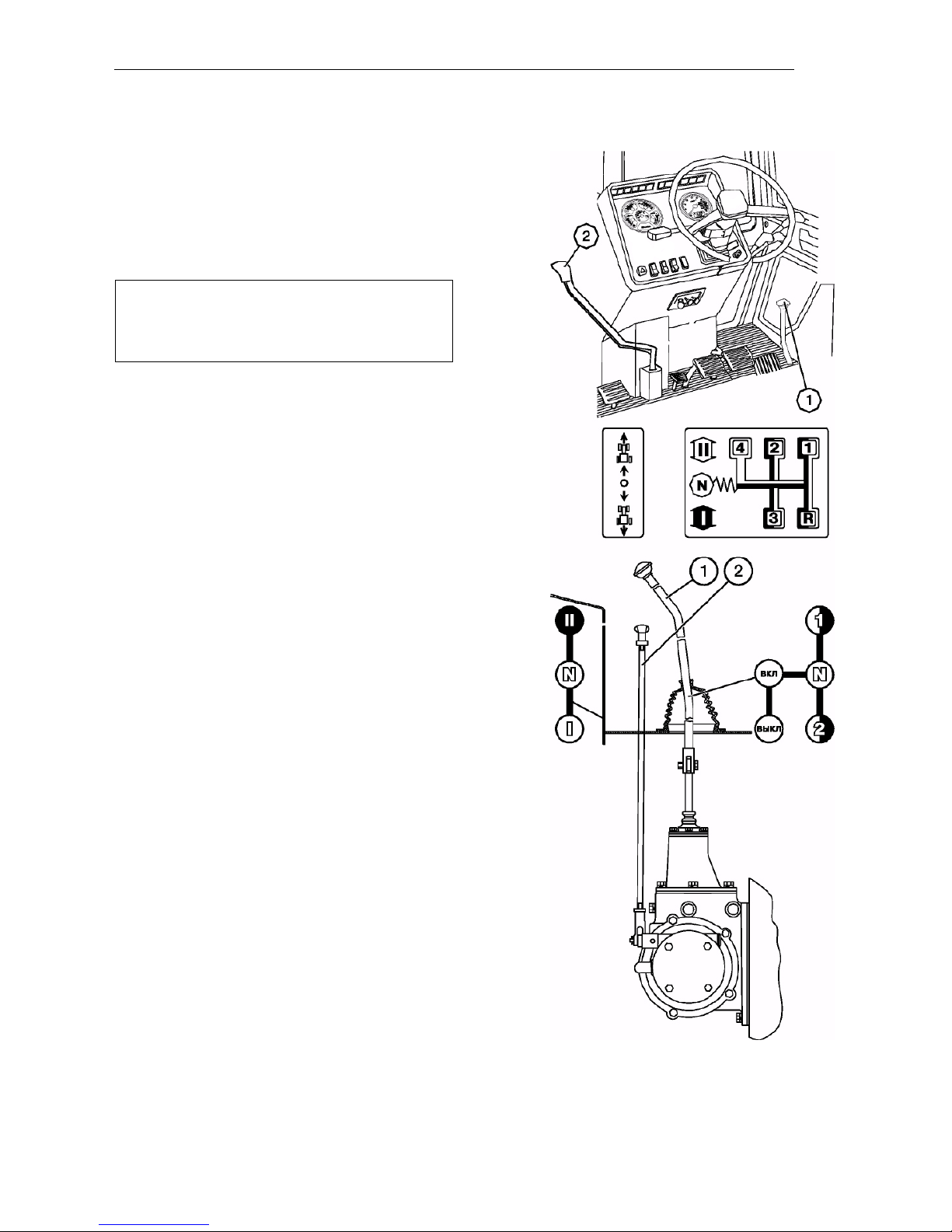
Controls and Instrumentation
MTZ series 900
36
Shuttle-gear control
(if installed)
The shuttle gear is controlled with lever (2) having
the following positions:
• ON – rearmost position;
• OFF (forward motion) – foremost position.
ATTENTION! When putting the gearbox
lever to position “R” (reverse motion),
the lever being in rearmost position, the
tractor will move forward.
Speed reducer control
(if installed)
The change-gear lever of the speed reducer (1) has
five positions:
• “OFF”;
• “ON”;
• “N” – neutral;
• “1” – first gear of the speed reducer;
• “2” – second gear of the speed reducer.
The rod for switching over the speed reducer ranges
(2) has three positions:
• I – first range corresponding to reduced
speeds (lower position);
• II – second range corresponding to increased
speeds (upper position);
• N – neutral (mid position).
Page 68
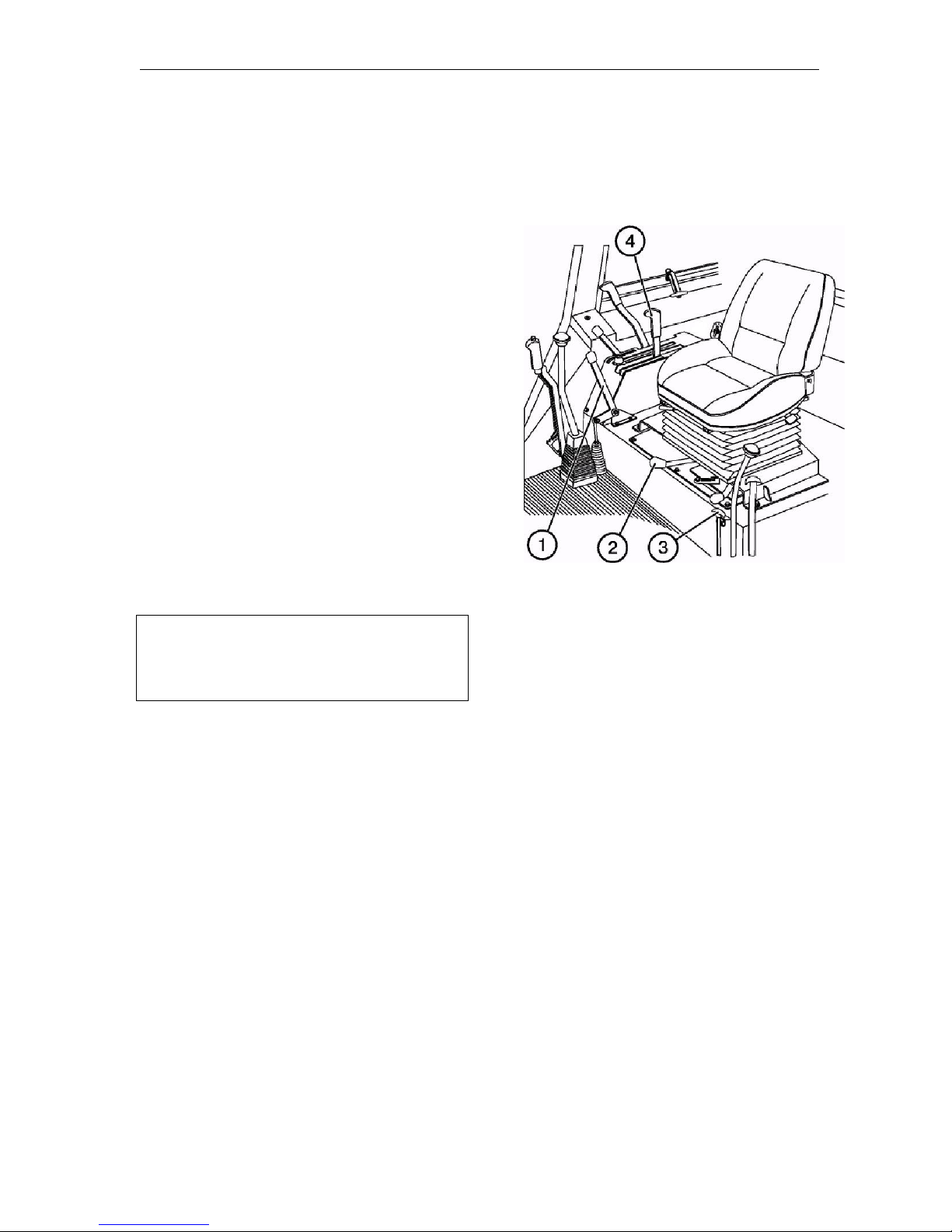
Controls and Instrumentation
MTZ series 900
37
Control of engagement of the front
driving axle (MTZ 920/920.2/
920.3/952/952.2/952.3)
The control lever (1) has three fixed positions:
• “FDA OFF” – lowermost position.
Use it when driving on hard surface
roads to prevent the increased wear of
the tyres.
• “FDA forcedly ON” – uppermost position. Only use this mode in case of
incessant skidding of the rear wheels
and when moving backwards, when
the engagement of the FDA is required.
• “FDA automatically ON (OFF)” – mid
position. In this mode, the FDA is engaged and disengaged automatically
by the free running coupling, depending on rear wheel skidding. Use this
mode during different field works.
ATTENTION! When using the tractor
without cardan shafts, put the control
lever (1) to the uppermost position
(“FDA forcedly ON”).
Hitch fixation mechanism control (2)
(for tractors with power governor)
Lever (2) has two positions:
• “Hitch unlocked” – rightmost position;
• “Hitch locked in upper position” – left-
most. To lock the hitch, lift the implement to uppermost position, having
put power governor arm (4) to position
«Lifting”, and turn handle (2) to the
left. Release down arm (4).
To unlock the hitch, lift the implement
and turn lever (2) to the right.
Control of lock of the hydraulic hook
(3)
The handle (3) has two positions:
• “Unlocked” – upper position;
• “Locked” – lower position.
To unlock the hydraulic hook, lift it with
arm (4) to upper position, pull handle (3)
up and fix it. To lock the hook after hitching the trailer to the tractor, lift the hook
with arm (4), release handle (3) from fixation and move it to lowermost position.
Page 69
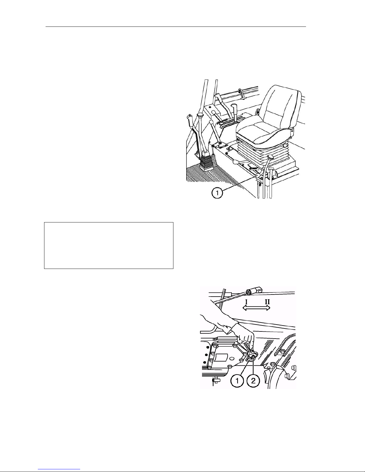
Controls and Instrumentation
MTZ series 900
38
Rear PTO control
Switch of the independent and synchronized drive of the rear PTO
Lever (1) has three positions:
• “PTO independent drive ON” – rightmost position;
• “PTO synchronized drive ON” – leftmost;
• “OFF” – mid position.
To engage the synchronized drive, proceed as follows:
• Start the engine;
• Step on the clutch pedal up to the
stop and put in the 1st or 2nd gear;
• release slowly the clutch pedal and
move simultaneously the lever (1) to
the leftmost position.
IMPORTANT! Use the synchronous
PTO drive in lower gears in the lowest
gears of the 1st and 2nd gearbox ranges
at the tractor motion speed not more
than 8 km/h. Otherwise power transmission can be damaged.
Switch of the 2-speed independent drive of the PTO (2)
The shifter arm (2) of PTO independent drive has two positions:
• I – 540 rpm – extreme, counter-
clockwise;
• II – 1000 rpm – extreme, clockwise.
To set the required PTO speed, release
bolt (1), rotate the shifter arm (2) to the I
or II position and retighten the bolt (1).
Page 70
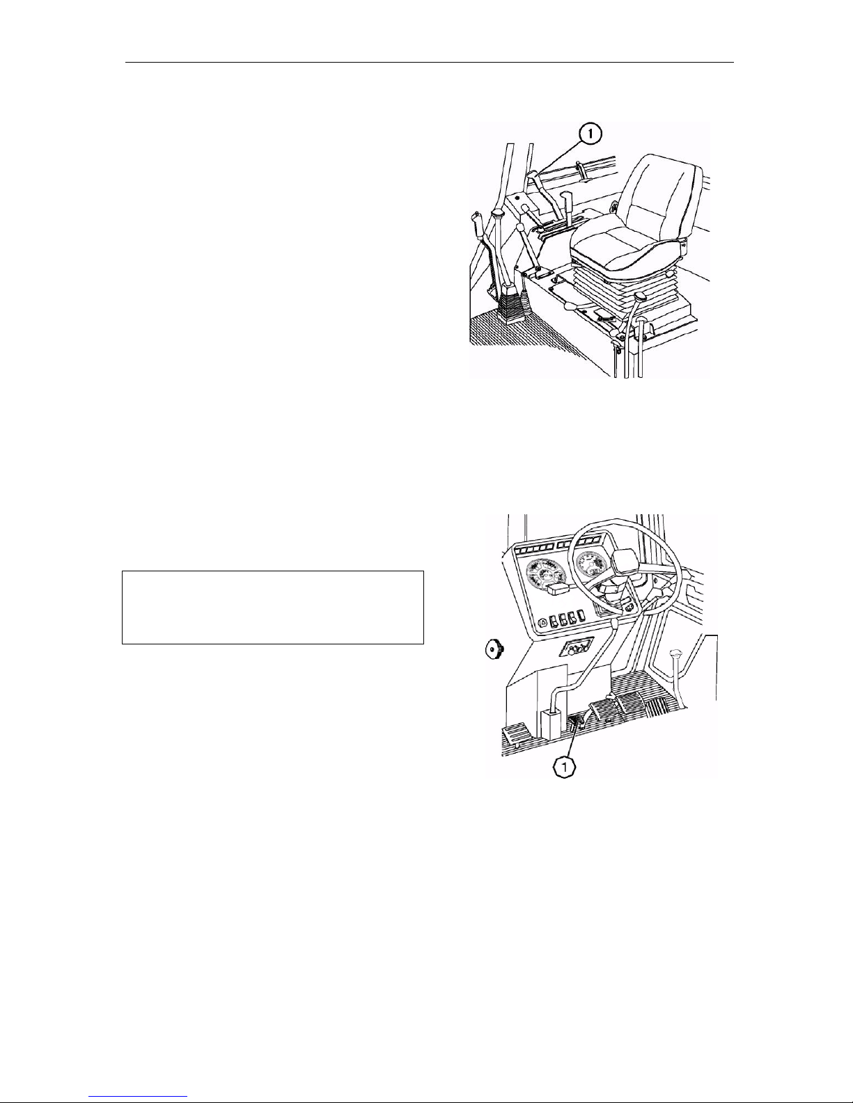
Controls and Instrumentation
MTZ series 900
39
PTO control lever
The PTO control lever (1) has two posi-
tions:
• PTO OFF – front position of the lev-
er (1);
• PTO ON – back position of the lever
(1).
Control of the rear axle differential
lock (1)
To engage shortly the lock press pedal
(1).
IMPORTANT! Engage the forced differential lock (1) only shortly to overcome
road obstacles and carry out the field
and transportation works.
WARNING: Do not use the differential
lock at the speeds exceeding 10 km/h
and when turning the tractor. Otherwise the tractor control becomes difficult and running gear and power
transmission are quickly worn out.
Page 71
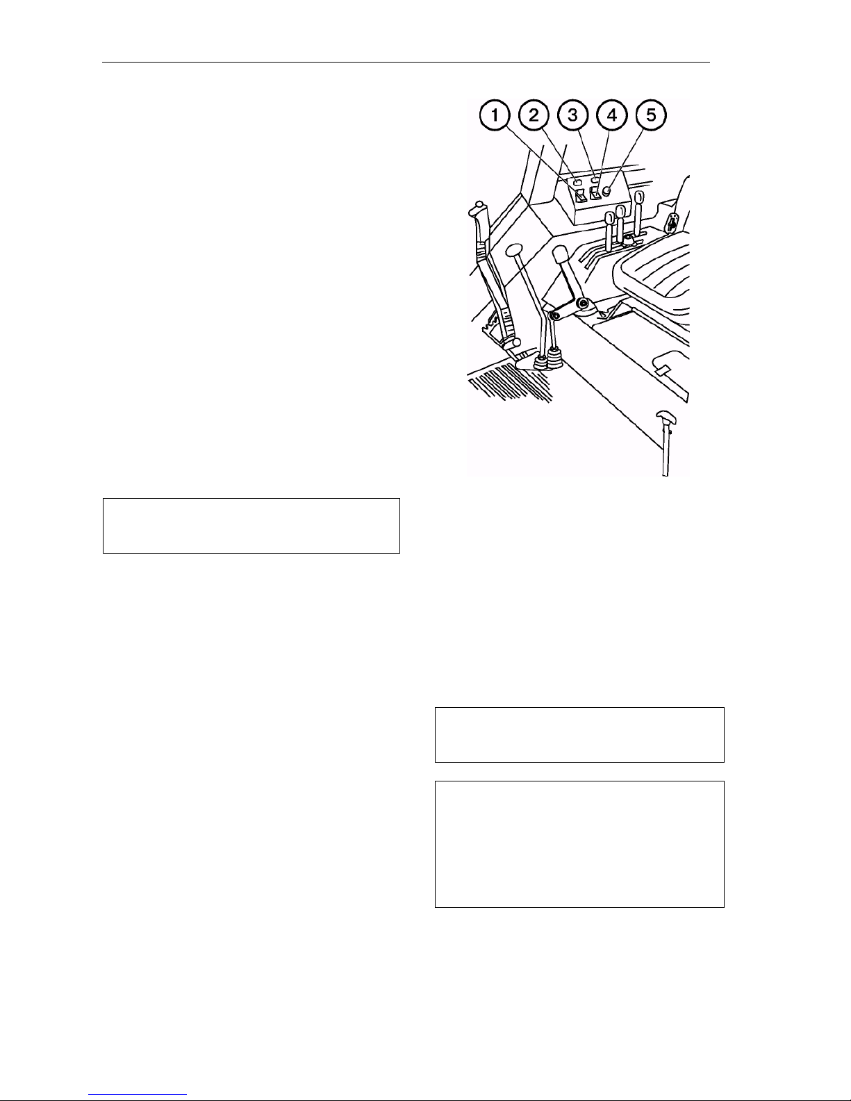
Controls and Instrumentation
MTZ series 900
40
Rear PTO control (for tractors
equipped with a hydraulic lift)
To engage the rear PTO, the key switch
(4) and push-button switch (5) located on
the panel above the right control board
are used. The switch (4) has two fixed
positions:
• “PTO ON” – when pressing the
lower part of the key switch;
• “PTO OFF” – when pressing the upper part of the switch.
To engage the PTO:
• Press the lower part of the key switch;
• Shortly press push-button switch (5).
Control lamp (3) will be on and PTO
shank will start rotating.
NOTE: On stopping the engine, the PTO
is disengaged automatically.
To disengage the PTO, press the upper part of the switch. The pilot lamp
will become dim.
ATTENTION! The PTO engagement
operations shall be only performed with
the engine running.
Rear axle differential lock control (for
tractors equipped with a hydraulic lift)
The differential lock (DL) is controlled
with key (1) having three positions:
• “DL OFF” – mid fixed position to be
used when performing the transport
works on the hard surface roads;
• “DL ON automatically” – by pressing
the upper part of the key (1). Fixed
position. It is to be used when performing the works with substantial rear
wheel skidding.
In the automatic mode, the rear wheels
are locked during the straight-line motion
and unlocked when turning the guide
wheels at the angle exceeding 13 in any
direction.
• “DL ON forcedly” – by pressing
the lower part of the key (1). Fixed position. It is to be used for locking shortly
the rear wheels when overcoming the
obstacles. On releasing the lower part of
the key, it returns to the mid position. On
activating the DL, the pilot lamp (2) lights
up, which becomes dim when unlocking
the DL in the automatic mode and on setting the key (1) to the mid position.
ATTENTION! Activate the DL under the
increased skidding conditions when performing the field and transport works.
IMPORTANT! Disable the DL at the
tractor motion speed exceeding 10 km/h.
Otherwise, the service lift of the power
transmission would be shortened and
the tractor control would be impeded.
The forced locking shall be used shortly
only to overcome road obstacles.
Page 72
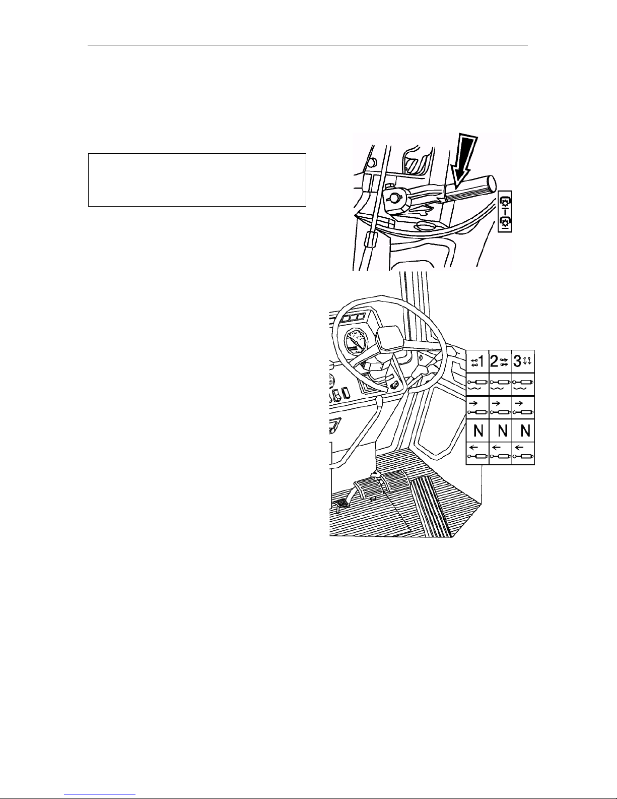
Controls and Instrumentation
MTZ series 900
41
Hydraulic system pump control
The control lever has two positions:
• “Pump ON” – upper position;
• “Pump OFF” – lower position.
IMPORTANT! Switch on the pump only at
the minimum rotational speed of the engine idling. Disengage the pump when
starting the cold engine and maintenance.
Control of the hydraulic system distributor (external cylinder)
Each of three arms controls the external
cylinders and has four positions:
• “Neutral” – lower mid position (fixed);
• «Lifting” – lower non-fixed position.
When releasing the arm, it returns to
“Neutral” (for the distributors Р80-3/4-
111; РП-70 -1221; РП-70-1221С;
RS213 Mita; RS213 MTZ). For the distributors Р80-3/4-222, this position is
fixed. The handles are returned automatically to the “N e utral” position at the
pressure of 15.5…20 MPa.
• “Forced lowering” – upper mid non-
fixed position between the “Floating”
and “Neutral” ones. On releasing the
arm, it automatically returns to “Neu-
tral”;
• “Floating” – upper fixed position.
NOTE: If any distributor arm is put into
the “Lifting” or “Lowering” position, the
operation of the power governor in the
automatic control, lifting and lowering
modes is interrupted.
Page 73
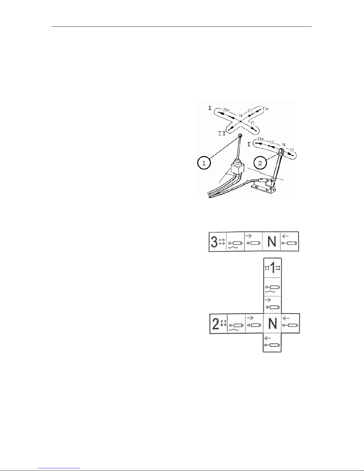
Controls and Instrumentation
MTZ series 900
42
Remote control of the hydraulic system distributor (if installed)
If the tractors are equipped with the RS213 MTZ hydraulic distributors, the remote control of the distributor spool
valves is executed by the manipulator
(joystick) (1) and arm (2) with the twoway cords. The manipulator and the arm
are mounted on the right control board
in the tractor cab.
The manipulator (1) makes it possible to
control two distributor spool valves (sections) at the same time:
When shifting the manipulator lever
lengthwise, the spool valve connected to
the left side outlets of the hydraulic system is controlled.
When shifting the manipulator lever
crosswise, the spool valve connected to
the right side outlets and rear outlets
(optional) is controlled.
The arm (2) can be only shifted lengthwise and controls the central spool valve
connected to the rear left outlets of the
hydraulic system.
Page 74
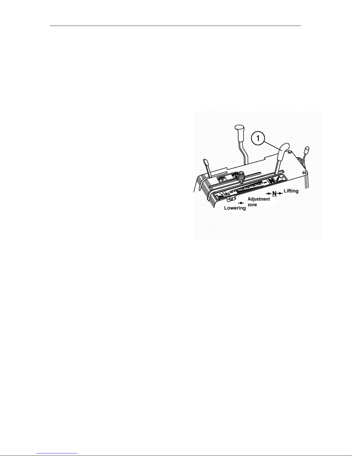
Controls and Instrumentation
MTZ series 900
43
Control of the power/position gov ernor of the hydraulic system
The control is performed by means of
the lever (1). The control method, either power or position shall be previously set.
The lever (1) has the following positions:
• “N” – “Neutral” (fixed position);
• “Lifting” – rearmost position (non-
fixed). Hold the lever with the hand
to lift the implement to the required
height. After releasing, it returns
back to “Neutral”;
• “Automatic control range” (control
zone) – between the “Neutral” and
“Lowering” positions. Beginning the
lowering of the implement corresponds to the control zone onset
(minimum cultivation depth). The
control zone end corresponds to the
maximum cultivation depth;
• “Lowering” – foremost position
(non-fixed). Hold the lever to lower the implement to the required
level. After releasing the lever, it
returns to control zone end.
NOTE: If any of the distributor levers
is set to the “Lifting” or “Lowering”
position, the power governor operation in automatic control, lifting or
lowering modes is interrupted.
Page 75
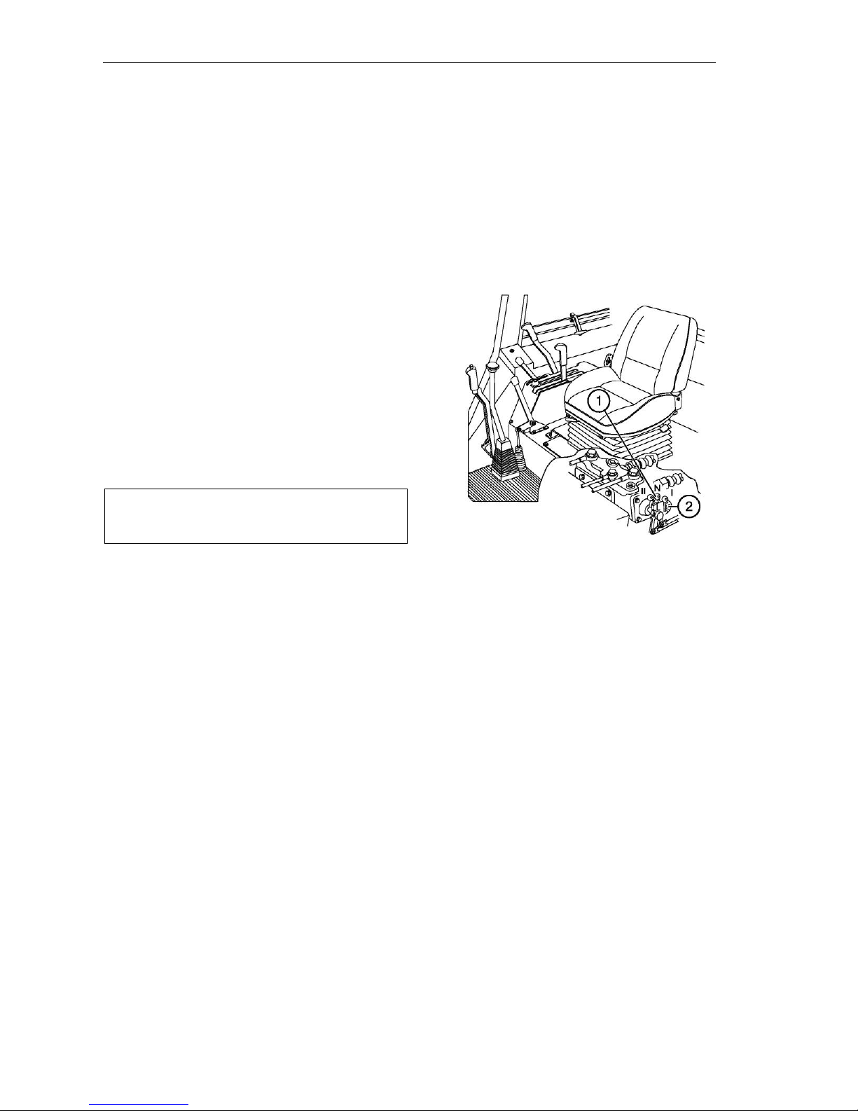
Controls and Instrumentation
MTZ series 900
44
Switch of power and position control methods (1)
To get access to the switch, remove the
cover under the seat. The switch has the
following positions:
• “N” – OFF;
• “I” – Power control;
• “II” – Position control.
Correction rate governor (2)
To reduce the implement position cor-
rection rate, turn the hand wheel (2)
clockwise until jerks transferred during
correction to the tractor are stopped.
ATTENTION! Prior to setting the lever
to the selected position, lift the RMA to
the uppermost position
Page 76
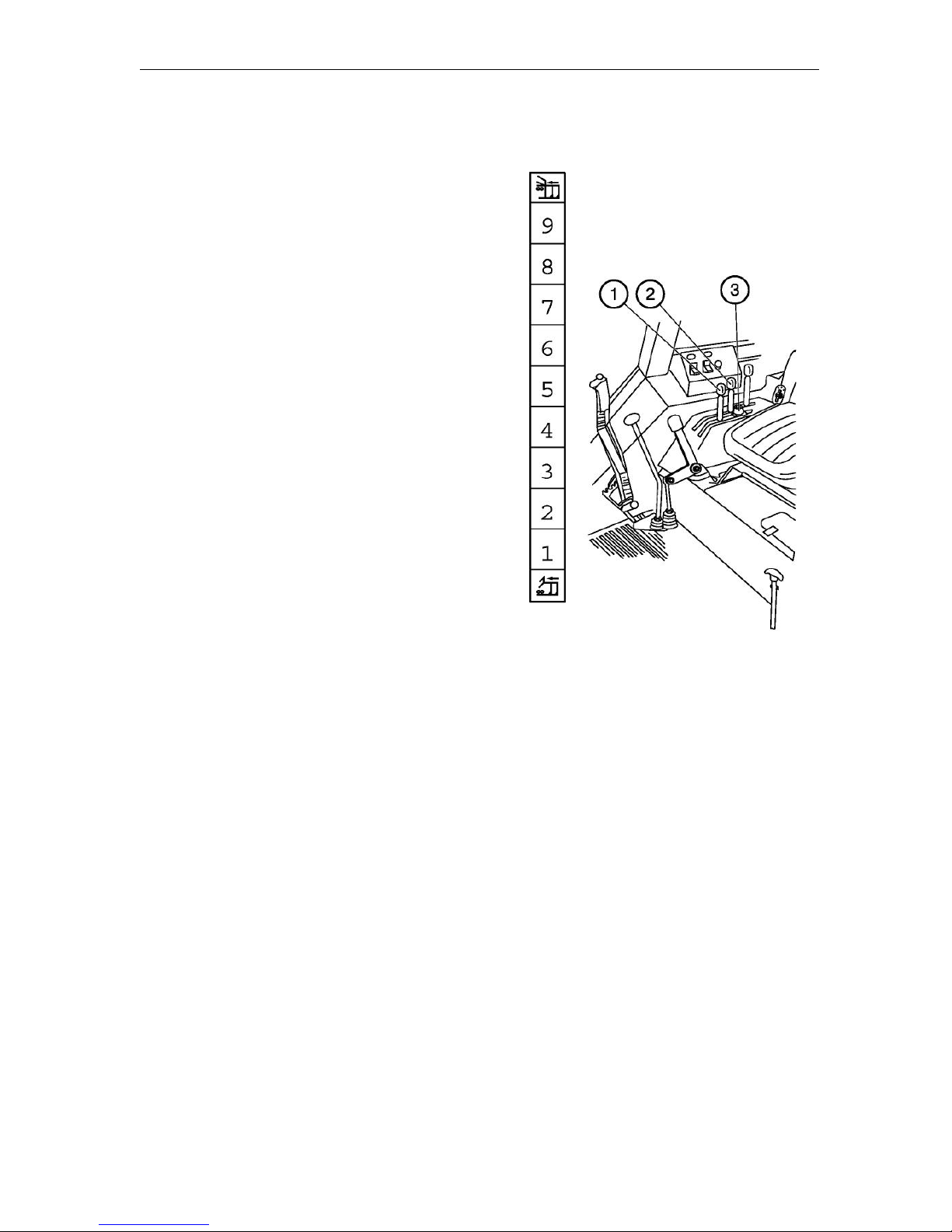
Controls and Instrumentation
MTZ series 900
45
RMA hydraulic lift control
The hydraulic lift is controlled by means
of two levers (1, 2) located on the board
in the cab at operator’s right hand.
The power control arm (1) is located
close to operator and has the following
positions:
Rightmost: maximum tillage depth (digit
“9” on the board);
Rearmost: minimum tillage depth (digit
“1” on the board);
Full control range of the soil cultivation
depth: from “1” to “9”.
Position control lever (2) has the following positions:
Foremost: minimal height of the implement above the soil surface (digit “9” on
the board);
Rearmost: transport position (digit “1” on
the board);
The maximum height of lifting the im-
plement by the position control lever is
provided by the adjustable stop (3).
NOTE: The combined control is provided
by limiting the tillage depth with the position control lever in the mode of power
control by means of the lever (1).
IMPORTANT! If any of the distributor
control handle is set to the “Lift” or “Low-
ering” position, the hydraulic lift control
by means of the levers (1, 2) is automatically ceased.
Page 77
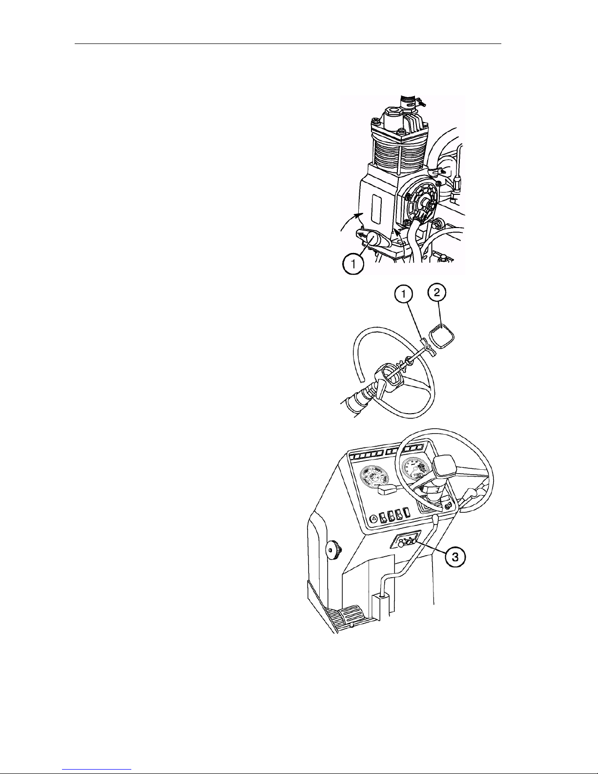
Controls and Instrumentation
MTZ series 900
46
Compressor control
The handle (1) has two positions:
• “Compressor ON” – when turning
the handle so that the arrow on the
arm would be directed backwards
with respect to tractor motion;
• “Compressor OFF” – when turning
the handle to 180 so that the arrow
would be directed forward with respect to tractor motion.
Changing the steering wheel position
To change the position of the steering
wheel by height:
• Remove the cover (2);
• Unscrew the clamp (1) by 3…5 turns;
• Move the wheel to the required posi-
tion;
• Tighten the clamp (1) by hand and
refit the cover (2).
NOTE: The steering wheel adjustment
range by height is 100 mm.
The steering column can be inclined to
four different positions from 25 to 40
with the step of 5. To incline the steering
column, pull the rod (3).
Page 78
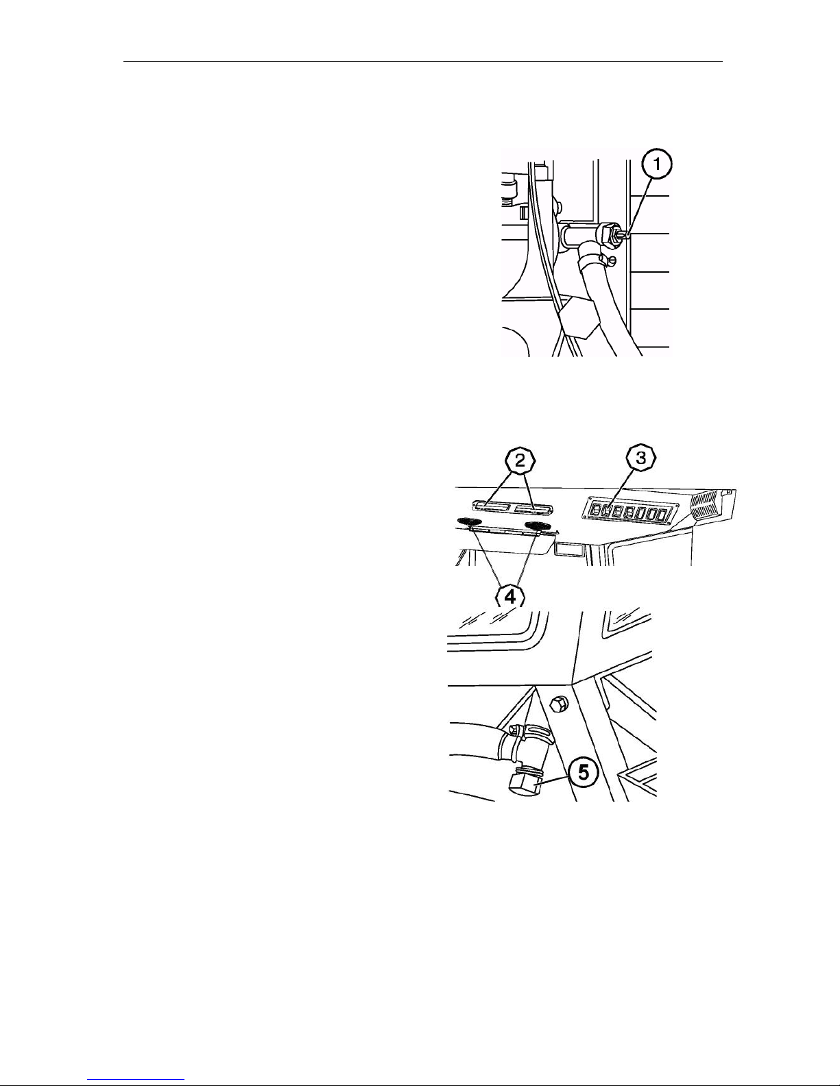
Controls and Instrumentation
MTZ series 900
47
Cab heater control
When switching the heater on, ensure
that the following conditions are met:
1. After filling the cooling system,
start the engine and let it work at a
medium rotational speed to heat water to the temperature of
+50C…+60C, after which open the
valve (1), increase the engine rotational speed and after 1-2 min make
sure that the cooling fluid circulates
through the heat exchanger by opening slightly the drain valve cap (5) on
the cab right side. The heat exchanger shall start warming-up. Then the
cooling fluid level in the engine cooling system radiator will decrease.
2. Add cooling fluid into the radiator
to the required level (50…60 mm below the upper edge of the filler neck).
3. Turn the heater fan on by means of
the switch (3) and direct the air flow
by means of air distributors (4).
4. The flow of fresh air delivered to
the cab can be controlled by opening
the recirculation flaps (2).
To drain the cooling fluid from the
heating system, the drain plugs (5)
are provided on the right and left
sides of the cab. After draining the
cooling fluid, it is necessary to blow
out the system, having closed preliminary the valve on the cylinder block
and unscrewed the plugs (5). After
blowing-out, tighten the plugs.
NOTE: The valve shall be closed to operate the system in the ventilation mode
during warm season.
Page 79
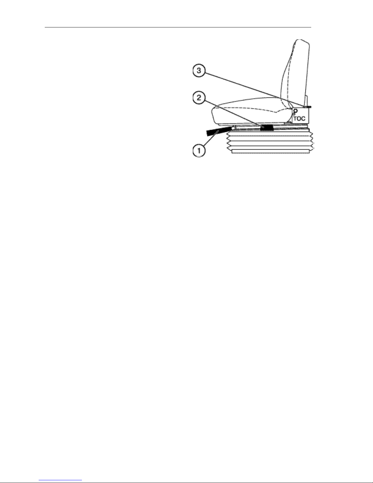
Controls and Instrumentation
MTZ series 900
48
MTZ Seat
The seat is provided with mechanical
suspension consisting of two spiral torsion springs and a gas-filled two-way
shock absorber. Shear-type guiding
mechanism ensures strictly the vertical
displacement of the seat. Dynamic motion of the seat is 100 mm.
The seat has the following controls:
1. Adjustment by operator’s weight
within the range from 50 to 120 kg
with indication of the suspension
travel middle position. Turn the
handle (1) clockwise (as seen from
the operator’s seat) to adjust the
seat to larger weight and vice versa.
2. Transverse adjustment within 80
mm from middle position. Lift the
lever (2) upwards to the stop and
move the seat forward or backward
to comfortable position.
3. Back inclination adjustment within
the range from 5 to 25. Lift the arm
(3) upwards to the stop, turn the
back and release the arm. The back
will be fixed in the given position.
The seat can be adjusted by height
within 30 mm by moving consequently
it manually upwards to increase the
height. To decrease the seat height, lift
it abruptly upwards to the stop and then
push it down.
Page 80
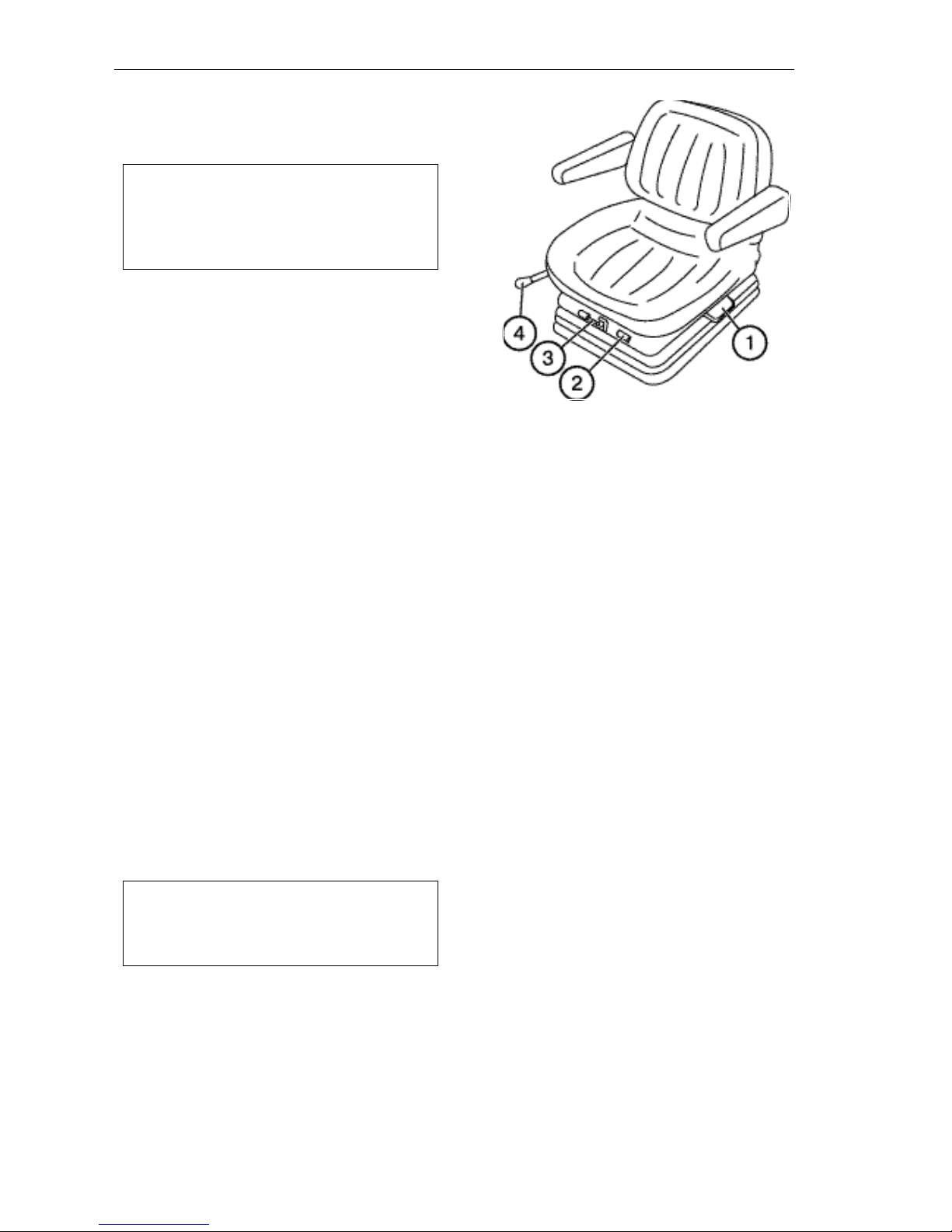
Controls and Instrumentation
MTZ series 900
49
Grammer Seat
(if installed)
Important! Prior to beginning the op-
eration of the tractor, adjust the seat
to the position being the most convenient for you. Perform all the adjustments while sitting on the seat.
The seat is provided with mechanical
suspension having the total travel of 100
mm and hydraulic shock absorber protected by a rubber boot.
The armrests being adjustable to height
and safety belts are standard.
The seat is equipped with the following
controls (handles):
1. Back inclination: to 12.5° forward and
5° backward with the step of 2.5°.
2. Weight indicator.
3. Weight control: from 50 to 130 kg
steplessly.
4. Forward/backward motions: within
the range of 150 mm with the step of
15 mm.
The adjustment of the seat height within
60 mm is provided in three positions. To
set the required height, pull the seat
upwards. The indicator click determines
a new position. Should the seat be
pulled upwards from the uppermost position, the lowering mechanism will operate and the seat will be lowered to the
lowermost position.
Note: Do not use solvents for cleaning the seat upholstery. Use only
warm water with small amount of detergent.
Page 81

Operating Instructions
MTZ series 900
81
OPERATING INSTRUCTIONS
Tractor pre-operation
When preparing a new tractor for operation, re-activate it: To do this:
• remove protective covers and plugs fitted on the engine;
• install peacocks of the radiator and cyl-
inder block;
• fill in all the refill tanks;
• u n pack the silencer put in the cab and fit it
onto the exhaust manifold so that exhaust
pipe outlet cut would be directed forward
along the tractor motion. Install the retain ing clip at the distance of 8…12 mm from
the silencer branch end. Tighten the clip
nuts with the torque of 44…54 Nm;
• drain the sediment from the coarse and
fine fuel filters and fuel tank;
• fill the fuel supply system with fuel and
bleed the system to remove air from it;
• check the fan belt tension;
• check and adjust the air pressure in the
tyres;
• make the service of the storage battery;
• tighten the fasteners;
• grease all the lubrication points using a
gun;
• check and adjust, if necessary, the
front wheel toe-in.
WARNING! To avoid injuries, make
sure that all protective guards are in
their places prior to starting the diesel engine.
ATTENTION! Starting a new engine,
which is not run-in, by towing is not allowed to avoid the intense wear of the
engine parts.
Running-in
Your new tractor will work reliably and
for long time, provided that running-in is
made properly and necessary maintenance is provided within the recommended terms. When executing the 30hour running-in, observe the following
rules:
1 . Watch constantly the instrument
readings and operation of lubricating,
cooling and feed systems. Monitor he
oil and fluid levels in refill tanks.
2 . Check the tightening and retighten the
external fastening junctions.
3 . Run in the tractor on light transport
and field works (harrowing, cultivation, sowing, etc.), gradually increasing the load at different gears.
4 . Do not overload the engine, do not
allow fuming or drop of the rotational
speed. The overload symptoms are
abrupt drop of the rotational speed,
fuming and failure to respond to
higher fuel feed.
5 . The operation of the tractor at very low
gear with small load at high rotational
speed of the engine will result in ex cessive fuel consumption. The correct
gear selection for each particular work
provides the fuel saving and reduces
the engine wear.
6 . Regularly perform time-shift mainte-
nance in accordance with recommendations stated in this Manual.
7. After running-in the tractor, perform
the maintenance works (see Section
“Maintenance”) .
Page 82
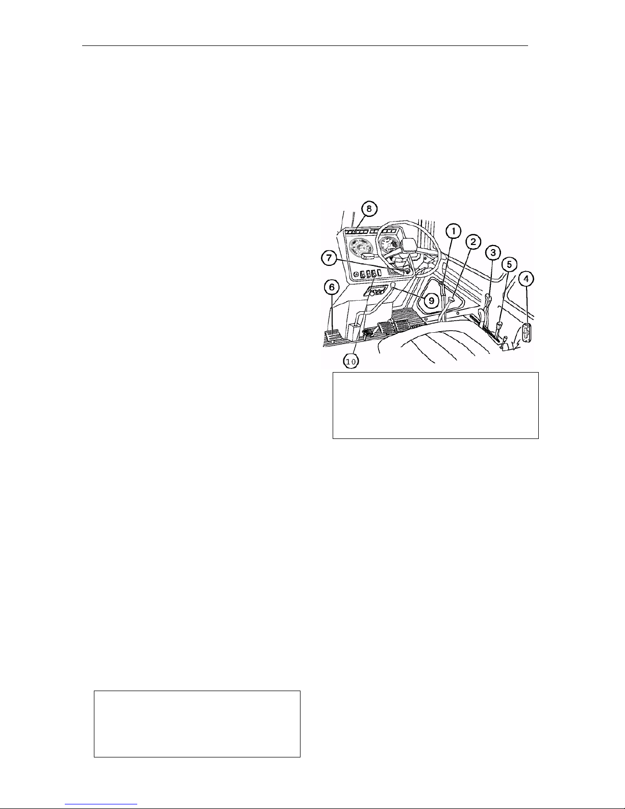
Operating Instructions
MTZ series 900
82
Starting the engine
Starting under normal conditions:
Check the level of oil in the crankcase and of cooling fluid in the radiator and the presence of fuel in the tank.
IMPORTANT! Never start the engine with the empty cooling system!
IMPORTANT! Start the engine and check the instrument operation while sitting in the
operator’s seat only.
WARNING: Never operate with tractor indoors.
IMPORTANT! The MTZ-
900.3/920.3/950/950.3/952/952.2/952.3 tractors are equipped with turbocharged diesel
engine. High rotational speeds of the turbocharger require the reliable lubrication when
starting the engine. Therefore prior to first
starting or after long-term storage, rotate the
crankshaft by the starter for 10 s without fuel
supply to lubricate the turbocharger bearings. Prior to loading the engine, let it run
idle for 2…3 min.
1 . Apply parking brake (1);
2 . Set the change gear lever (2) to neutral
position, move it to the leftmost position and hold it in this position until the
start is completed and the step-down
reducing gear lever (9) to the extreme
position (back or front);
3 . Set the PTO lever (3) to the OFF posi-
tion and the “Synchronous–
Independent” switching lever – to the
“Neutral” position;
4 . Set the ground switch (4) to the ON posi tion;
5 . Set the fuel feed arm (5) to the mid-
dle position;
6 . Step on the clutch pedal (6);
7. Turn starter key (7) to the position II
(Start) and hold it until the engine is
started, but not more than 15 s. Then
the start control light in the pilot lamp
block unit (8) will light up. When the
engine starts running, the light shall
become dim. If the engine fails to
start, repeat starting after at least
30…40 s.
ATTENTION! If the starter fails to operate and the pilot lamp of the starter
control board blinks at low frequency
(about 1.5 Hz), this indicates that the
change gear lever is not in neutral po-
sition or there is a breakage in the
start locking circuit. If the light blinks at
high frequency (about 3 Hz), there is a
failure in the alternator circuit (terminal
“W” or ”~”).
8. Release the clutch pedal (6). After
starting the engine, check the operation of all indicating lamps and instrument readings (cooling fluid temperature, oil pressure in the engine
and storage battery charge).
Let the engine run at 1000 rpm to stabilize the oil pressure in the operating
range.
Page 83

Operating Instructions
MTZ series 900
83
Starting at low temperatures
(+4°С and below)
Important! To avoid the damage of the
power gear, do not push or pull the
tractor to start the engine by towing.
The engines of the MTZ-
900.3/920.3/950.3/952.3 tractors are
equipped with glow plugs. When
energizing them, the plugs get redhot and heat the air taken into
each engine cylinder.
At steadily low temperatures, use
the winter oil grades in the engine
crankcase, gear box and hydraulic
system in accordance with the
recommendations of this Manual.
Keep storage batteries always
charged.
Use pure winter diesel fuel not
contaminated with water.
To avoid failures, drain sediments
from the coarse fuel filter and fuel
tanks every day.
Attention! If the tractor is equipped
with electric torch pre-heater, use
previously published “Operating
instructions”.
Procedure of starting the engine
at low temperatures:
• Switch off the hydraulic system
oil pump drive to reduce the resistance to the crankshaft turning;
• Check the level of oil in the en-
gine pan and of cooling fluid in the
radiator;
• Apply the parking brake to keep the
tractor from motion;
• Set the change gear lever and
the range lever (2) to the neutral
position, move it to the leftmost posi-
tion and hold it in this position until
the start is completed and the stepdown reducing gear lever to the extreme position;
• Set the PTO control lever (3) to the
OFF position and the “Synchronous–
Independent” switching lever – to the
“Neutral” position;
• Set the ground switch to the ON posi-
tion;
• Set fuel feed control arm (5) to the
mid position;
• Step on the clutch pedal;
• Hold the key in the “I” position for
more than 2 s. Then the starting aid
warning lamp will light up at the pilot
lamp block, signalling about the
glow plugs energizing. Hold the key
in this position. As soon as the
warning lamp starts blinking at the
frequency of 1 Hz, the glow plugs
and the engine are ready for starting;
• Turn the starter key to the “II” posi-
tion and start the engine under normal conditions as stated above. After starting the engine, the pilot
lamp will become dim and audible
warning will be silenced.
Note: The system ensures the oper-
ation of the glow plug within 3
minutes after starting the engine
(then the pilot lamp is off).
Attention! If the glow plug pilot
lamp lights up in the blinking mode
at the frequency of 2 Hz after starting the engine and operation within
3 minutes, this indicates that the
glow plugs are not switched off after finalization of the full cycle by
the system. Shut down the engine,
turn the ground switch off and
eliminate the failure. A probable
reason can consist in sticking the
electromagnetic relay contacts.
• Release the clutch pedal. Warm up
the engine.
Page 84
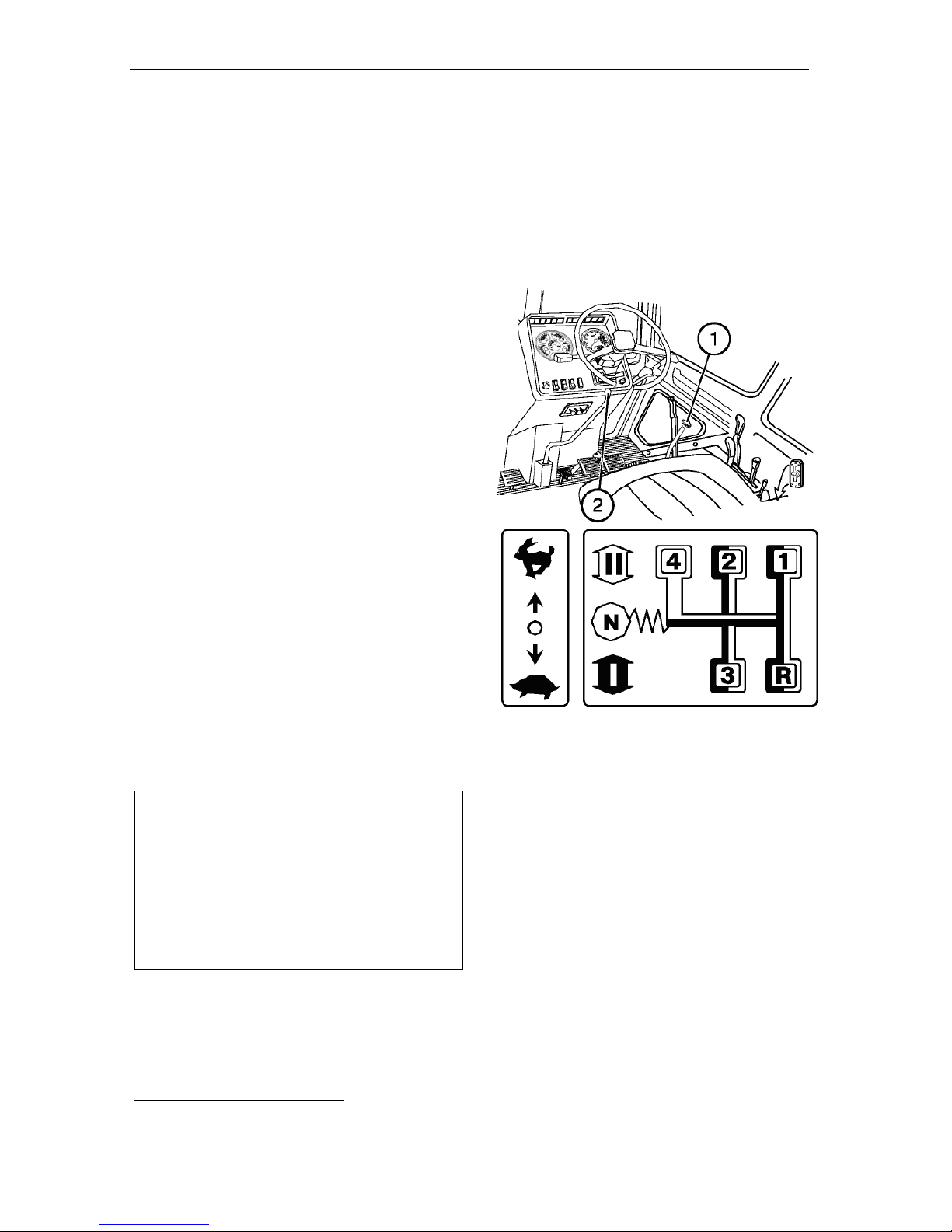
Operating Instructions
MTZ series 900
84
Starting the tractor motion
ATTENTION! When selecting the re-
quired gear, use the gearbox switching
diagram.
To start the movement, proceed as follows:
• step on the clutch pedal fully;
• select the required gearbox range;
• shift the lever (1) to the leftmost po-
sition and set the range II or I, respectively, by moving the lever forward or backward;
• return the lever to the neutral position
and then to the right, select the required gear and set the required speed
by moving the lever (1) forward or
backward;
• set the lever 2 to the required extreme position (forward or backward)*.
Release the parking brake and release smoothly the clutch pedal while
increasing slightly the fuel feed. On
starting the motion, increase the fuel
feed.
Avoid starting the motion with high traction load (e.g. a plough deepened into
the soil).
ATTENTION! Always step on the
clutch pedal prior to engaging the
range (step) and putting in the gear.
Do not hold the foot on the clutch pedal
during operation on the tractor, since
this can lead to clutch slipping, its overheating and failure.
*
Forward – direct gear, back – reducing the speed
for tractors with reducing gear and increasing the
speed for tractors with multiplier.
Page 85

Operating Instructions
MTZ series 900
85
Stopping the tractor
To stop the tractor:
• Reduce the engine crankshaft speed;
• Step on the clutch pedal;
• Set the change gear lever to neutral
position;
• Stop the tractor by applying the service brakes;
• Apply the parking brake.
Steering control
IMPORTANT! The tractors are
equipped with the hydrostatic power
steering system. If the engine is
stopped, the pump does not supply the
system and it begins automatically operating in the manual mode where turning the tractor requires applying more
force to be applied to the steering
wheel.
IMPORTANT! To stop the tractor in
case of emergency, step on the clutch
pedal and twinned service brakes pedal at the same time.
Shutting down the engine
IMPORTANT! Prior to shutting down
the engine, lower the implement onto
the ground and let the engine operate
at 1000 rpm within 1…2 min. This will
decrease engine temperature.
To shut down the engine, proceed as follows:
• set manual fuel feed arm to minimal feed
position (back to the stop);
• disengage the PTO and set all the dis-
tributor’s levers to neutral position;
• lower the implement onto the ground;
• pull engine shut-off lever cord handle to
fully stop the engine;
• turn ground switch off to avoid storage
battery run-down.
Page 86
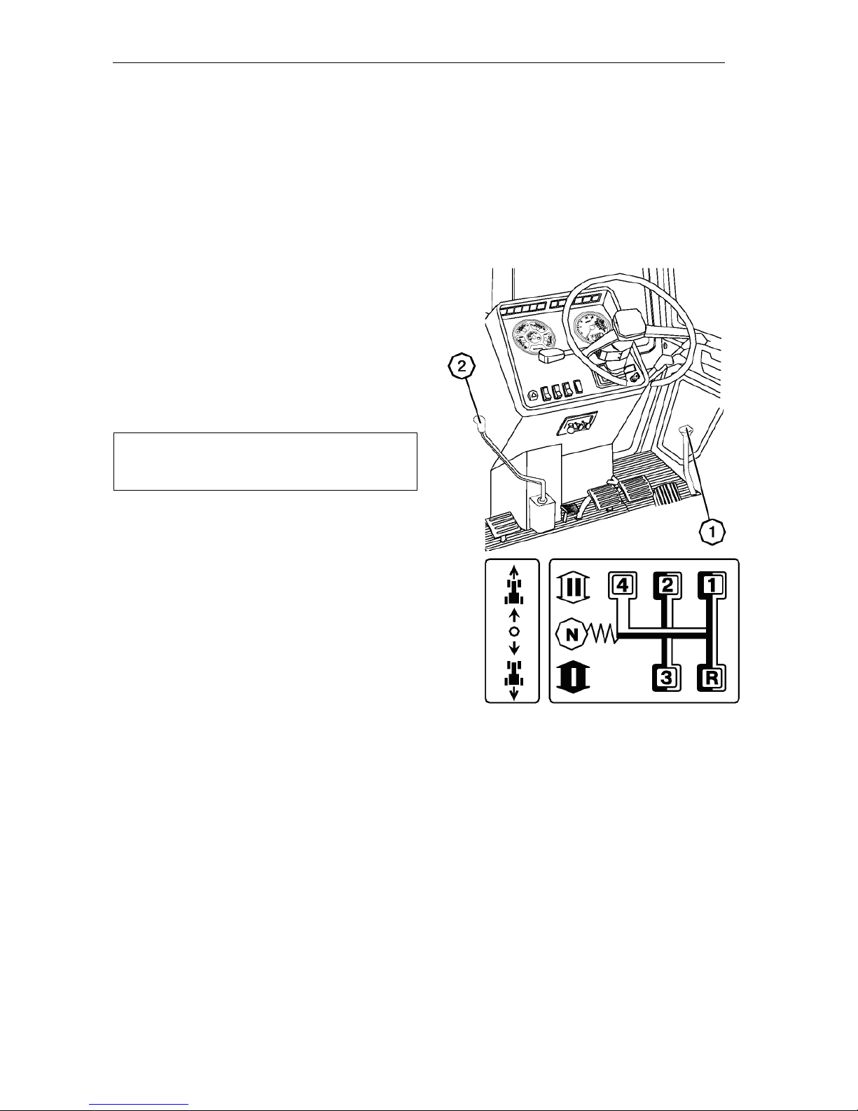
Operating Instructions
MTZ series 900
86
Switching over the transmission with
a shuttle gear (if installed)
Switch the gearbox and the shuttle gear in
accordance with the changeover scheme.
Using the tractor in the “shuttle” mode
makes it possible to change quickly the di rection of the tractor motion by means of
the lever (2) without using the change
gear lever (1).
The shuttle gear control lever (2) is
located under the steering column
(unlike the reducing gear lever, it is
bent to the left) and has two positions:
• “Reverse OFF” – foremost position;
• “ Reverse ON” – rearmost position.
IMPORTANT! When changing motion di -
rection, step on the clutch pedal and stop
the tractor.
NOTE: When the shuttle gear is engaged
and the change gear lever (1) is set to the
gear I-R and II-R, the tractor moves for ward.
Page 87
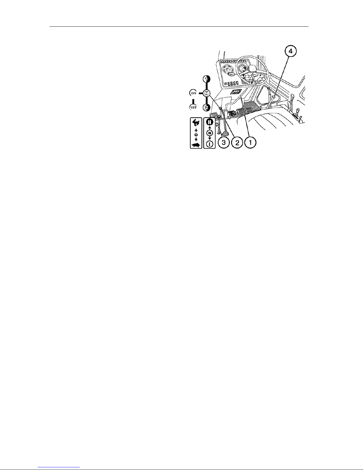
Operating Instructions
MTZ series 900
87
Operation of the tractor equipped with a
speed reducer (optional)
1 . Set the change gear lever (4) to neutral
position and reducing gear lever (1) to
foremost or rearmost positions.
2 . Set the speed reducer controls as fol-
lows:
• gear handle (2) to the “ON” position;
• range rod (3) to the “N” position
(neutral).
To start the tractor motion:
1 . Set the minimum idling speed of the
engine.
2 . Step on the clutch pedal.
3 . Set the speed reducer gear handle from
position ON to neutral.
4 . Select the required speed reducer gear.
5 . Set the required speed reducer range.
ATTENTION! It is forbidden to put in the
2
n d
gear of the speed reducer range II at
the 2
n d
gearbox reverse gear.
6 . Put in the required gear of the gearbox
in the range I.
7 . Release smoothly the clutch pedal. If
necessary, increase fuel feed.
8 . Adjust the tractor speed by varying fuel
feed.
Speed reducer gear switching
1 . Set the minimum engine idling speed.
2 . Step on the clutch pedal.
3 . Wait for 3…5 s and then set the change
gear lever to the neutral position.
4 . Put in the required speed reducer
drive.
5 . Put in the 1
s t
gear of the gearbox.
6 . Release smoothly the clutch pedal.
7 . Adjust the speed by the foot-operated
or manual fuel feed control.
Stopping the tractor
1 . Set the minimum engine idling speed
2 . Step on the clutch pedal.
3 . Wait for 3…5 s and then set the change
gear lever to neutral position.
4 . Stop the tractor by applying the service
brakes. Apply the parking brake.
Page 88

Operating Instructions
MTZ series 900
88
Hydraulic system
The hydraulic system for three-point rear
attachment control is equipped with power
governor*, which ensures system operation
in the following modes:
• power control;
• position control;
• height control.
Power and position control
The power/position control makes the system sensitive to variation of operating conditions. Effective application of these
modes depends on the unitized machines
and land conditions.
Position control
It provides the accurate and sensitive moni -
toring of the position of the attached
equipment like spraying machine, leveller
and others above the ground. The position
c o ntrol can be used with the tillage ma-
chines, semi-hookup ploughs with external
cylinders, etc. However, it is not recom-
mended to use this control on uneven fields
when using the tillage machines and im-
p l ements.
Hydraulic lift (if installed)
The HMS with hydraulic lift provides for op -
eration in the following modes:
• lifting the RMA and lowering it under its
own weight;
• position control;
• power control;
• combined control (adjusting the cultiva-
tion depth according to the soil condi tion with limiting the maximum depth by
the position control).
*
Th e MTZ tractors with index “.2” are
equipped with RMA hydraulic lift and do
not have power governor
Power control
It is the most suitable mode for operation
with mounted implements, the working
parts of which are deepened into the soil.
The system is sensitive to traction effort var iation (caused by the changes in the soil re sistance or soil tillage depth) via central rod
of the hitch mechanism. The hydraulic sys tem responds to these changes by lifting or
lowering the implement to maintain the giv en tractive force at constant level. The sys tem reacts to the compressing and stretch ing forces in the central rod, i.e. is a dualaction system.
Height control
When tilling the soil with greatly varying
density and resistance, and uneven sur face, if the power o r position control does
not ensure satisfactory tillage quality ac cording to land treatment requirements, it is
recommended to use the height control
(using the implements with supporting
wheels).
Page 89
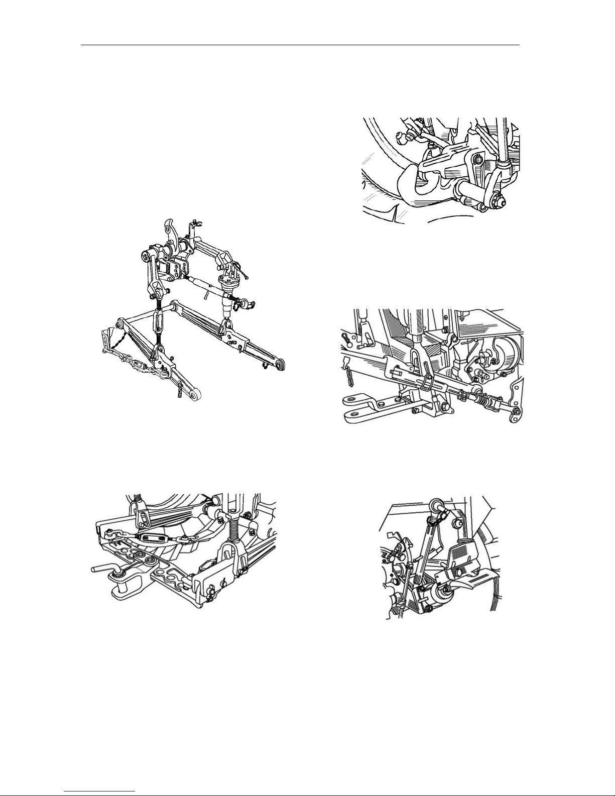
Operating Instructions
MTZ series 900
89
Working equipment to attach agricultural machines to the tractor
(for tractors with power governor)
ATTENTION! Prior to attaching the ma-
chines read carefully this section.
Rear three-point mounted attachment:
to join mounted and semi-mounted agricultural machines – ploughs, seeders, cultivators, spraying machines, etc.
Traction hitch mechanism (cross-bar)
ТСУ-1Ж: to work with trailing machines,
potato combines and others (except single-axle ones) with the speed of up to 15
km/h.
ATTENTION! Using the ТСУ-1Ж when
performing the transportation works is
strictly forbidden.
Traction hitch mechanism ТСУ-2 (hy draulic hook): to operate single-axle
trailers and other machines.
Traction hitch mechanism ТСУ-1М
(floating lever): to operate with heavy trail-
ing machines (optional). A combined variant
with a hook for working with the semitrailers.
Traction hitch mechanism ТСУ-ЗК (trail -
er gear with automatic hitch): to operate
two-axle trailers.
Page 90
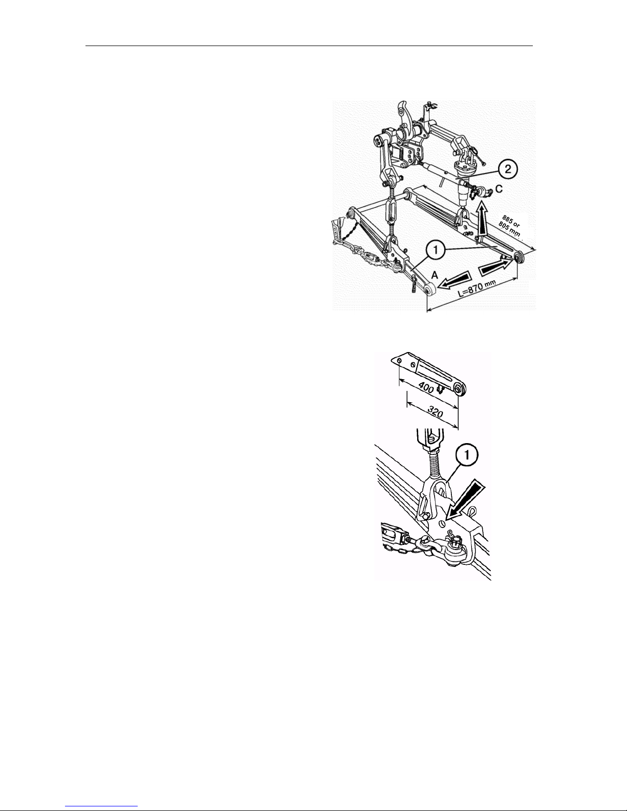
Operating Instructions
MTZ series 900
90
Rear mounted attachment (HMS
with power governor)
The second-category three-point mounted attachment ensures the connection of
mounted and semi-mounted agricultural
machines and implements to the tractor
with the following attachment components:
• hanger axle length “L” (distance be-
tween joints “A” and “B”) is equal to
870 mm;
• machine support height is 460 mm;
510 mm;
• pin diameter to connect to lower rod
joints (1) is 28.7 mm;
• pin diameter to connect to upper rod
(2) is 25 mm.
The lower rods consist of two parts:
• front part or rod itself;
• rear end with the ball joints. Standard
length of the low rod: 885 mm.
To increase the hanger length, install the
rod ends with deflected front joints (Ф704605050-01/055-01).
To increase the load-carrying capacity of
the mounted unit, replace the rear rod
ends (400 mm long) by the rod ends
having the distance of 320 mm between
the joint axis and the front aperture (Н50-
4605040А2/045А2). Total lower rod
length will become 805 mm.
ATTENTION! When the rod length is
805 mm, the carrying capacity of the
mounted unit will be increased by 10%
with decreasing the lifting height by 10%.
The same load-carrying capacity can be
ensured by installing the angle brace (1)
at the additional points (the lifting height
will be also decreased by 10%).
В
Page 91
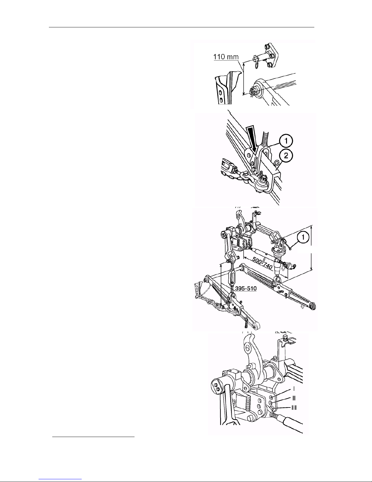
Operating Instructions
MTZ series 900
91
To increase the clearance when cultivat ing the high-stem crops, install the front
en ds of the lower rods onto the additional hanger axles located at the distance of
110 mm above the lower rod axis. To imitate field profile crosswise when operating wide-cut implements, connect the
angle braces (1) with lower rods (2) via
longitudinal grooves.
IMPORTANT! To avoid the damage of
the angle brace, the angle brace fork
grooves shall be behind the aperture.
Upper rod and angle braces
The upper rod length is adjusted within
500…740 mm. The length of the right ad justable angle brace can be adjusted
within 425…520 mm by rotating the h a n dle (1). When being shipped from the
fa ctory, the right angle brace length is set
to the standard value of 475 mm. When
the tractor is shipped from the factory,
the left (non adjustable) angle brace
length is set to standard 475 mm.
During operation, the left angle brace
length can be changed within 395…510
mm, depending on the standard equip ment of the tractor and type of unitized
machines and implements.
IMPORTANT! Make adjustment of the
implement laterally with the right angle
brace only.
Depending on the tillage depth and soil na ture, install upper rod to one of the three
*
positions:
I – light soils and small tillage depth at
power control;
I I – medium soils and medium tillage
depth at power control;
I I I – heavy soils at large tillage depth, as
well as at position control or without
power governor.
*
For tractors equipped with HMS with hydraulic
lift, the upper rod is installed in one position.
425-520
Page 92
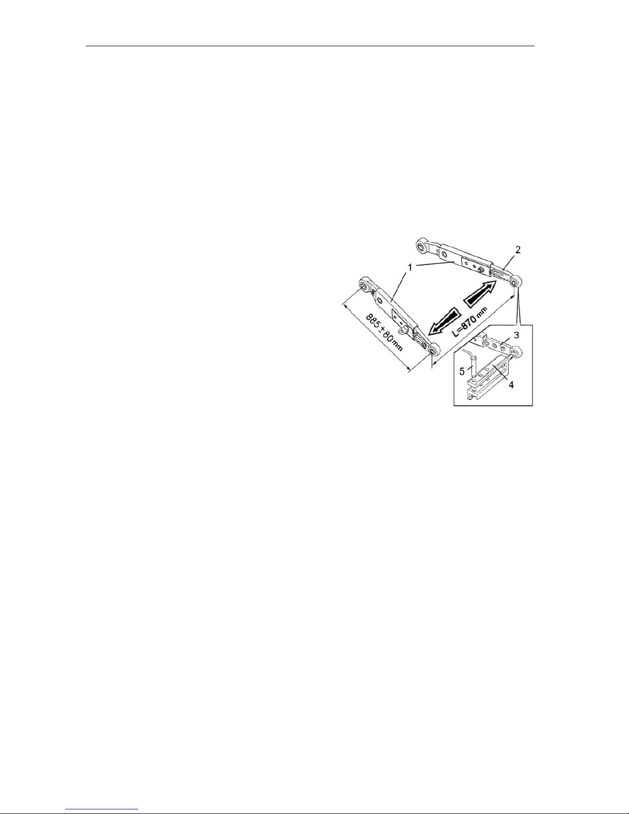
Operating Instructions
MTZ series 900
92
Reinforced rear mounted attachment
The tractors with power governors may
be equipped optionally with a reinforced
rear mounted attachment with telescopic
lower rods, which are to be installed onto
the shaft with the diameter of 35 mm instead of that with the diameter of 32 mm.
If necessary, the length of the rods equal
to 885 mm may be adjusted stepwise
with the step of ± 80 mm, in this case,
the carrying capacity of the mounted attachment will be varied.
For working with trailed agricultural machines, the double cross-bar (4) for the
lower telescopic rods (1) with the pivot
(5) is optionally delivered. In this case,
its tips (3) are fitted instead of the rear
ends of the rods (2). The distance from
the end face of the PTO to the pivot
(hitching point) in such version will be
470 mm
ATTENTION! It is strictly forbidden to
use the double cross-bar when performing the transportation works.
Page 93
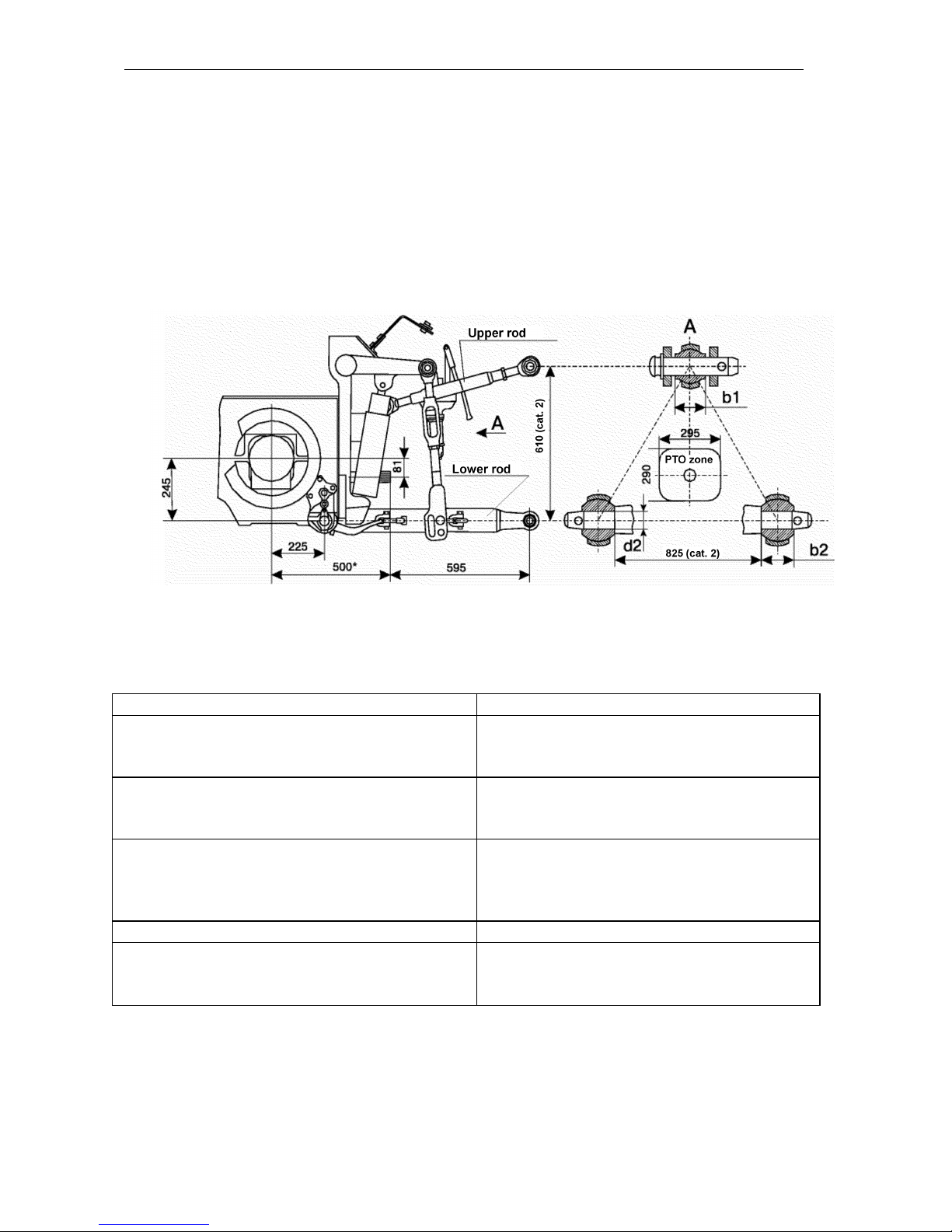
Operating Instructions
MTZ series 900
93
Rear mounted attachment of the tractors equipped with the hydraulic lift
Machines: mounted (ploughs, cultivators, seeders, cutters, etc.), semi-mounted
(ploughs, soil-tilling units, seeders, potato combines, etc).
Lower rods
Telescopic, one-piece - optional
Length of lower rods, mm:
telescopic
one-piece*
805,885,985
885
Rod joint width, mm: upper (b1)
lower** (b2)
51
38 or 45
Nominal diameter of attachment components,
mm:
upper rod pin**
lower rod joints (d2)
22 or 25 2 8
Distance from PTO face to hanger axle
595
Load carrying capacity, kN (kgf):
on hanger axle
on 610 mm overhang
43 (4300)
27 (2700)
______________________________________________
* Optional – rods with quickly connectable attachment
* * (Quickly connectable attachment). To be agreed when acquir ing the tractor.
Page 94
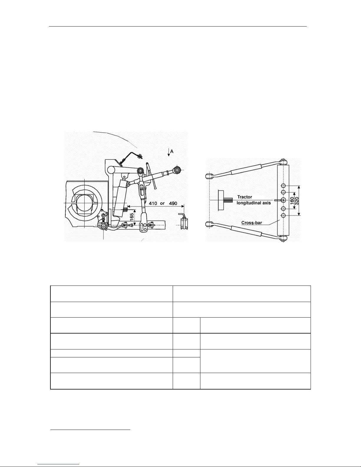
Operating Instructions
MTZ series 900
94
Traction hitch mechanisms (THM) of the tractors equipped with hydraulic lift
ТСУ-1Ж-01 (double cross-bar)
ТСУ-1* (single cross-bar)
Machines: semi-mounted (seeders, potato-planters, potato combines, vegetableharvesting machines, etc.), semi-trailer (mowing machines, balers, haulm gatherers,
etc.).
ТСУ-1Ж-01 (double cross-bar)
as a unit with telescopic rods – optional
ТСУ-1 (single cross-bar)
with one-piece or telescopic rods on hanger
axle – optional
Telescopic rod front end length
mm
570
Distance between PTO face to attach-
ment pin axle
mm
410,490,595*
Attachment pin size
mm
030 (0 30 )
12(1200) 6,
5* (650)*
Vertical load on THM
kN (kg f)
Machine turning angle relative to the
tractor
degree
± 65 (± 80)
*
Indices are given for ТСУ-1
Page 95
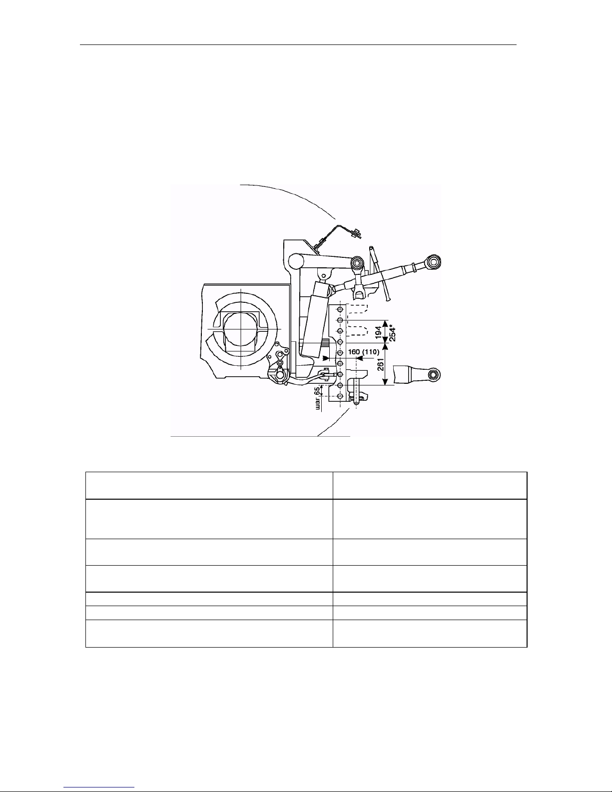
Operating Instructions
MTZ series 900
95
Г15 Lifting THM of the tractors equipped with hydraulic lift
1.ТСУ-2В (fork)
Machines: semi-trailed (semi-trailers, machines for fertilizing, etc.), trailed (disk harrows,
tillers, hoeing ploughs, hitch of harrows, cultivators and seeders, etc.).
Hitch mechanism
Fork with the possibility of the vertical displacement
Distance from the fork to supporting surface for
machines without PTO drive, mm
403.. .858 (91 8*) stepwise
via 65 mm
Fork position for machines with PTO drive
Lowermost or
uppermost
Distance from PTO face to attachment pin ax-
le, mm
160 or 110
Attachment pin diameter
40
Vertical load on THM, kN (kg f)
20 (2000)
Machine turning angle relative to the tractor, degree
±65
* With turning over the fork
Page 96
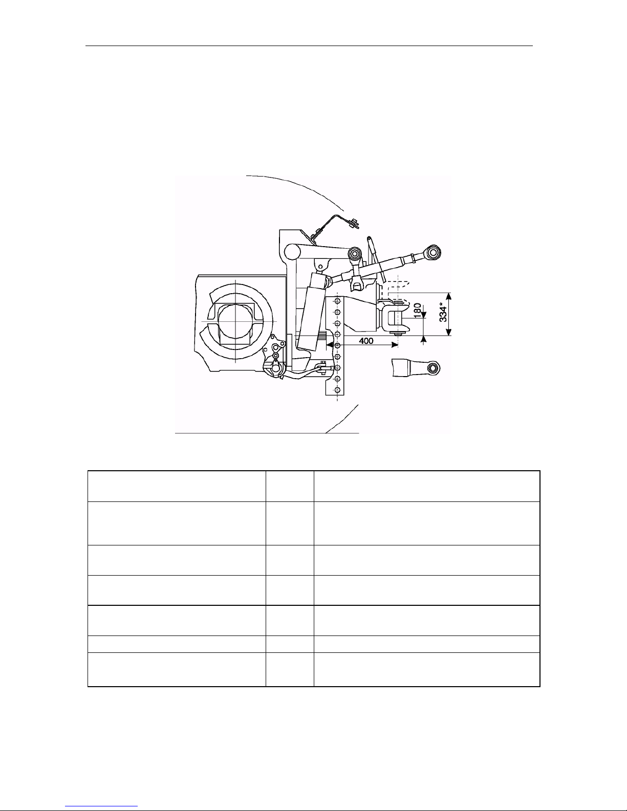
Operating Instructions
MTZ series 900
96
2. ТСУ-ЗВ (fork)
Machines: trailed (automobile-type two-axle trailers, etc), semi-trailed (same as for ТСУ1Ж-01).
Hitch mechanism
Rotating fork with vertical displacement
Distance from the fork to supporting surface for machines without
PTO drive, mm
mm
288.. .808 (962*) stepwise via 65 mm
Fork position for machines with
PTO drive
lowermost or uppermost, including overturn
Attachment pin size
mm
040
Distance from PTO face to attachment pin axle, mm
mm
400
Vertical load on THM
kN (kg f)
12 (1200)
Machine turning angle relative to
the tractor
degree
± 55 (trailers),
± 85 (agricultural machines)
* With turning over the fork
Page 97
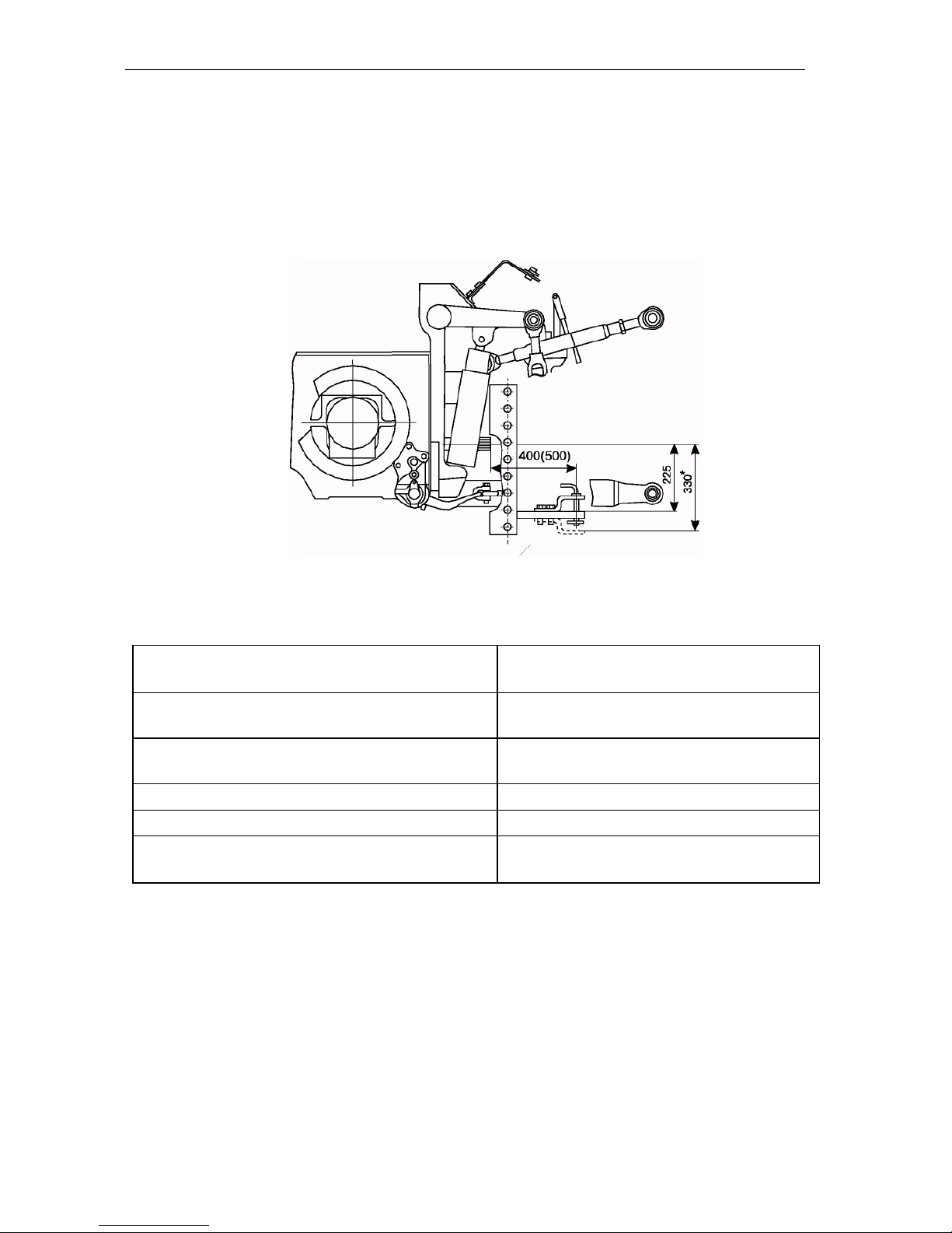
Operating Instructions
MTZ series 900
97
Г17 3. ТСУ-1М (dragbar)
Machines: heavy trailed with active drive of driven elements.
Hitch mechanism
Fork with variation of position relative to
PTO face
Distance from the fork to supporting surface,
mm
402 (297*)
Distance from PTO face to attachment pin
axle, mm
400 or 500
Attachment pin diameter, mm
30
Vertical load on THM, kN (kg f)
12 (1200)
Machine turning angle relative to the tractor,
degree
±85
Page 98
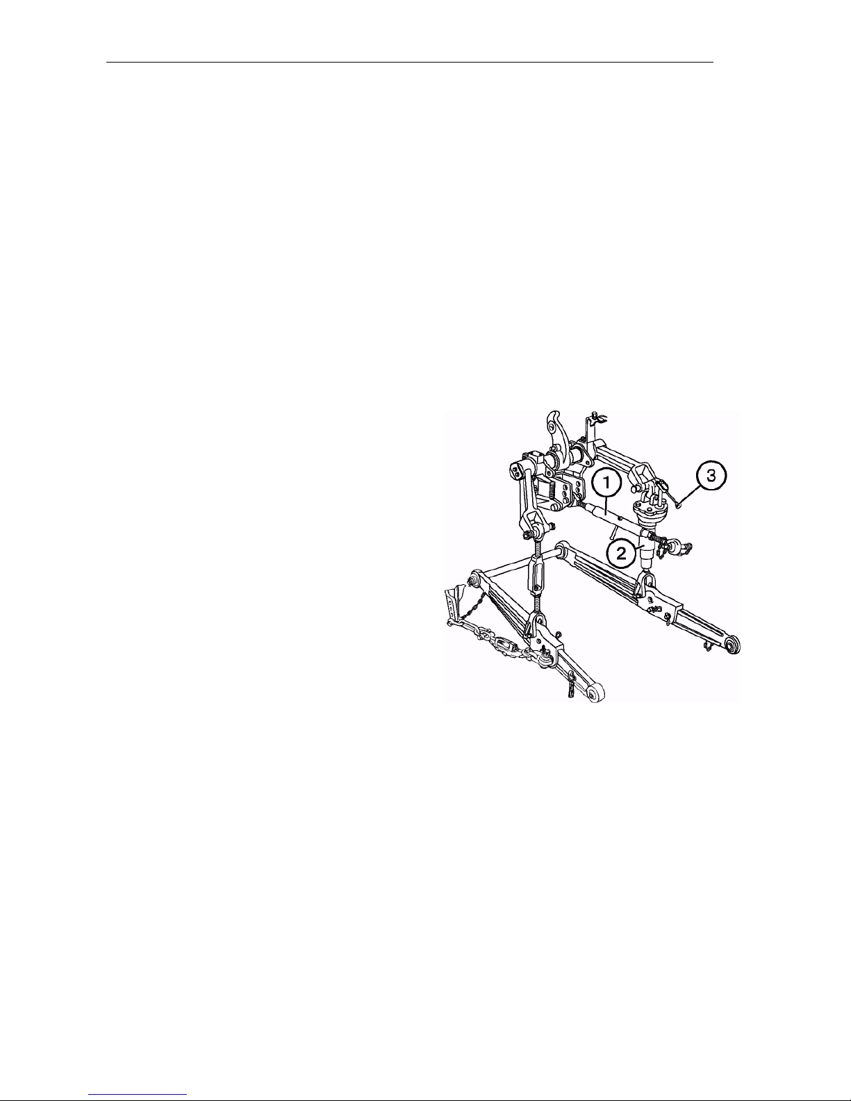
Operating Instructions
MTZ series 900
98
Hitching machines to the tractor
1 . When hitching machines to the tractor,
make sure first that there is nobody
within hitching zone.
2 . Lower the attached device to the lower
position by using the power governor han dle, drive the tractor back and attach the
machine to lower rods. Splint the pins.
Stop the engine.
3 . Make the upper rod (1) longer or shorter
and connect the rod ball joint with the
machine. Splint the pin.
4 . If necessary, adjust the upper rod to ini-
tial or required length.
5 . If necessary, adjust the machine lateral
tilt by using the right adjustable angle
brace (2). Increase the angle brace
length, turn arm (3) clockwise and vice
versa.
6 . Prior to operation, check that:
• the tractor parts are not in dangerous proximity to machine components;
• the central rod is not in contact with
PTO enclosure at the lowest position of the machine;
• the PTO cardan drive is not extremely long, with large joint angles and
there are no thrust forces;
• the PTO enclosure is not in contact
with that of machine cardan drive.
7 . Slowly lift the machine and check the
clearance of at least 100 mm between
the tractor and the machine in lifted
position.
8 . Check the lateral swing of lower rods
and, if necessary, adjust them by using tie rods.
Page 99
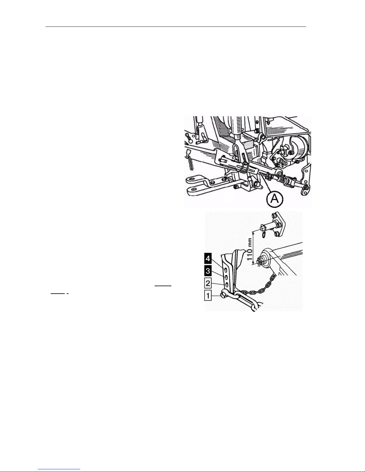
Operating Instructions
MTZ series 900
99
The machine (implement) is also attached
to the tractor by the automatic hitch CA-1
connected to the tractor hookup at three
points (two rear joints of longitudinal rods
and rear joint of the central rod).
To prevent spontaneous disconnection of
the machine from the tractor, fix the automatic hitch latch with a spring cotter pin.
Limiting (telescopic) tie bars (А)
The tie bars are use to limit lateral swinging of hanger lower rods both in transport
and working states. This is especially required during the works on the slopes,
near the excavation pits, wall, etc.
Rear end of the tie bar is attached to the
lower rod and the front one – to the holder in one of four positions, depending on
the works:
• Position 1. The tie bars exclude implement swinging in transport state.
• Position 2. The tie bars exclude implement lateral swinging both in transport
and working states.
IMPORTANT! Positions 3 and 4 should
be used only when installing lower rods
onto additional axes of the hanger (upper
axes).
• Position 3. The tie bars exclude implement lateral swinging in transport state.
• Position 4 The tie bars exclude implement lateral swinging both in transport
and working state.
ATTENTION! The tie bars shall be installed only into the second from bottom
apertures for holders (position 2) to
avoid tie bar failure.
Page 100
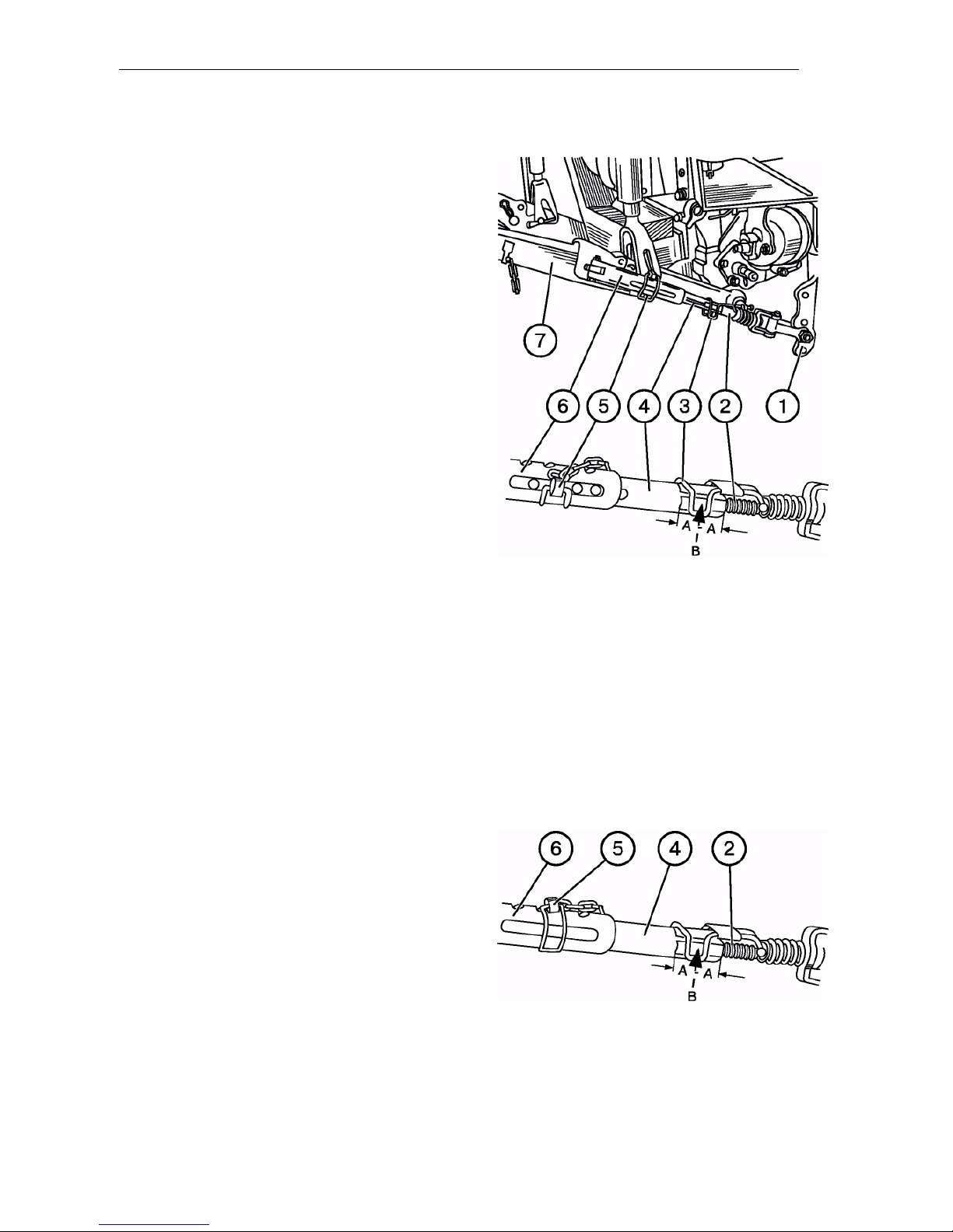
Operating Instructions
MTZ series 900
100
Partial locking of telescopic tie bars
To ensure the required lateral displace-
ment of the machine, e.g., a plough, adjust
the tie bars in the operating condition as
follows:
• rotating the screw (2), set the handle
(3) at the middle of flat “B”;
• pull out the cotter (5) from the tie bar;
• attach the machine to the lower rods
(7) and raise it a little to pull off the
ground;
• having aligned the apertures of the internal
tube (4) with the groove of external tube (6),
insert the cotter (5) in the middle of the groove
IMPORTANT! Install the cotter (5) so
that it is in the middle of the groove or at
minimal displacement towards the tractor. Otherwise, tie bars can be damaged.
Prior to transportation, lift the machine to
the up position and check its lateral
swinging, which shall not exceed 20 mm
in each direction. If necessary, adjust the
swinging by rotating the screw (2).
Full tie bar locking
For complete locking of the machines,
e.g. a cultivator or attached unit, adjust tie
bars in the working state similar to their
partial locking, except for the last operation during which align the aperture of the
internal tube (4) with that of external tube
(6) and insert the cotter (5).
Ensure full locking in transport state (the
machine being lifted) by tightening screw
(2) into tube (4) to the maximum.
 Loading...