

Page 1

MTZ
1220.1 / 1220.3
1220.1 – 0000010 OM
OPERATOR'S MANUAL
2010
Page 2

In view of constant upgrading of produced goods, the construction of some units and parts
of tractor may undergo changes which are not reflected in present edition.
Some technical data and illustrations given in this book may differ from those on your tractor. Dimensions and weights are approximate (advisory). For detailed information please
consult your MTZ Dealer.
_______________________________________________________________________
RUE “Minsk Tractor Works”, 2010
All rights reserved. No part of this book may be reproduced in any form without written
permission of RUE “MTW”.
Page 3

MTZ-1220.1/1220.3 Table of contents
TABLE OF CONTENTS
INTRODUCTION…………………………………………………………………………………... 1
SAFETY REQUIREMENTS……………………………………………………….. B1
GENERAL INFORMATION………………………………………………………………….. C1
OPERATING CONTROLS AND INSTRUMENTS ……... D1
DESCRIPTION AND OPERATION OF TRACTOR CONSTITUENTS……………………. E1
TRACTOR PREPARING FOR OPERATION ……………………………………………... F1
OPERATING INSTRUCTION………………………………………………………………. G1
ADJUSTMENTS ……………………………………………………………………………… H1
COUPLING OF IMPLEMENTS ………………………………………………………………. I1
POSSIBLE FAILURES AND GUIDELINES FOR TROUBLESHOOTING J1
SCHEDULED TECHNICAL MAINTENANCE ……………………………………… K1
TRACTOR TRANSPORTATION AND TOWING ……………………………. L1
TRACTOR STORAGE ……………………………………………………………………. M1
TRACTOR DISPOSAL………………………………………………………………….. N1
ANNEXES
Advisable fuels, oils, lubrication materials for tractors MTZ- -
1220.1/1220.3»……………………………………………………….
An1
Electrical circuit diagram of the DL, FDA and PTO control system of “MTZ
1220.1/1220.3” tractors (with GB 16x8)
An6
Electrical circuit diagram of the DL, FDA, PTO and gearbox reduction unit control sys-
tem of “MTZ-1220.1/1220.3” tractors (with GB 24 x12)
An7
Electrical circuit diagram of MTZ - 626/826/926/1220.1/1220.3 tractors An9
Page 4

MTZ 1220.1/1220.3 Section А. Introduction
А1
Section . INTRODUCTION
The present operator’s manual is designed for studying the structure, operation
rules and maintenance of tractors MTZ-1220.1/1220.3.
Read this manual carefully and fulfill requirements set forth in this manual.
Failure to follow this instruction can lead to operator's injury or a breakdown of
a tractor.
Operation of a tractor, its maintenance and repair shall be carried out only by
employees, familiar with all of its parameters and characteristics and informed about
necessary safety requirements to prevent casualties.
In connection with constant development of the tractor some changes, which
are not depicted in the present manual, can be introduced in the structure of certain
units and parts.
Long-term and reliable tractor performance is secured in the case of proper
operation and timely maintenance.
Any arbitrary changes made by a consumer release the manufacturer
from responsibility for possible further injuries to the operator and tractor
breakdown.
Tractors “MTZ -1220.1/1220.3” are universal wheeled tractors of the 2nd drawbar category with 4x4 wheel arrangement and designed for multiple agricultural operations with mounted, semimounted, trailed implements, and for loading and unloading and hauling operations.
Tractors “MTZ -1220.1” is a basic model with diesel engine D-245.2S2 with rated
power of 90 kW.
Tractors “MTZ -1220.3” is a modification with diesel engine D -245.2S2 with rated
power of 90 kW, muffler on the right side of cab column.
TO OPERATORS ATTENTION!
The tractor must be run-in for 30 hours. It is recommended to load a diesel
engine only up to 80% of the rated power until the first MS-1 (in 125 hours).
2. Your tractor is equipped with range-type gearbox. In addition the ranges are
shifted with toothed couplings, and gears within each range are shifted by virtue of
synchronizers.
To throw into the range proceed as follows:
–– Depress the clutch pedal and await complete tractor stop;
— Throw into the required range smoothly, without jerks, using the range engaging
lever;
— Smoothly release the clutch pedal.
To change geasr proceed as follows:
— Depress the clutch pedal;
— Shift the gearshift lever smoothly, without sharp jerks, and hold it in depressed
position until the gear is completely actuated;
— Smoothly release the clutch pedal.
You can change the gears in motion within the range only during the hauling operations on the hard-surface and dirt roads. Never attempt to change the gears in motion
Page 5

MTZ 1220.1/1220.3 Section А. Introduction
А2
when a tractor unit is used in the cross-country conditions (arable fields, peat beds,
sandy soil etc.) because sudden stop of the tractor-machine unit can occur. Cross
the mentioned sections with previously selected gear.
Failure to comply with the stated operation rules will cause quick wearing out of gear
splines and tooth-type couplings as well as synchronizers impairment
Attention! If you hear skirr when shifting ranges and gears with the clutch pedal
being depressed, immediately turn to a repair shop for malfunction repair.
3. Observe the rules of PTO switch. When switching PTO move control lever smoothly with 2…4 sec. hang-up in the centre of motion from neutral position to PTO switch
in order to prevent shaft breaking, reducer gears breaking and tail breaking of PTO.
4. When adjusting operating and parking brakes make sure that the ground is horizontal, the engine is not running, rear wheels from front and back are supported by
wedges to exclude accidental movement of the tractor.
Adopted abbreviations and symbolic notations.
AB — accumulator battery;
RADL — rear axle differential lock;
PFE — paper filter element;
TDC — engine piston top dead center;
PTO — power take-off shaft;
PIS — power intake shaft;
HLL — hydraulic lift linkage;
HSU — hydrostatic steering unit;
SMS — shift-time maintenance service;
SPTA — spare parts, tools and accessories;
RHL
IVR
— rear hitch linkage;
— integral voltage regulator
SFE — safety filter element of engine air cleaner;
GB — gearbox;
TMU — tractor-machine unit;
CC — clutch coupling;
MS — maintenance service;
THM — towing hitch mechanism;
MFE — main filter element of engine air cleaner;
FDA — front driving axle;
HACS —hydraulics automated control system
SM — season maintenance;
VFL — volatile flammable liquid
CAC — engine charge air cooler;
TC — engine turbocharger.
Page 6
MTZ 1220.1/1220.3 Section А. Introduction
А3
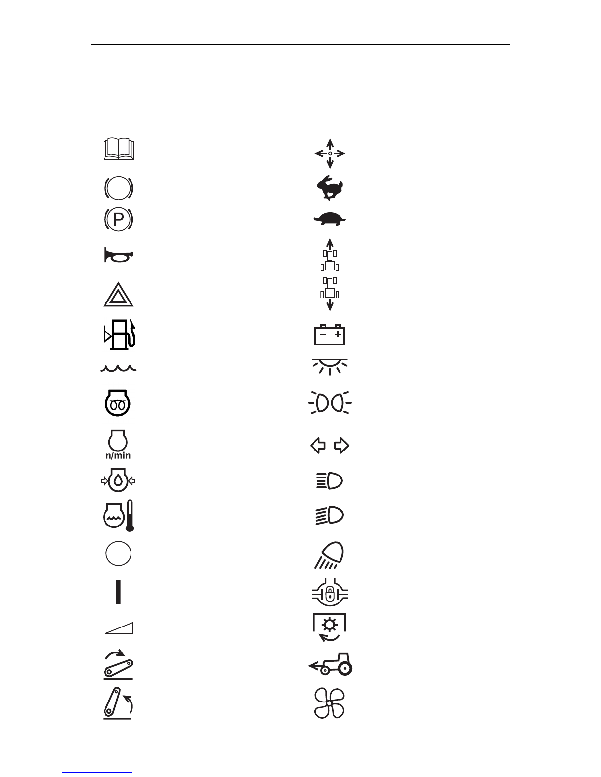
International Symbols
Manufacturer uses standard international symbols regarding instruments and operating controls.
Symbols with their meaning are given below.
— see operators manual
— control operating direction
— brake
— fast
— parking brake
— slow
— horn
— forward
— alarm signaling
— reverse
— fuel level in the tank
— battery charging condition
— coolant
— cab dome light
— starting preheater plug
— marker lights
— engine speed
— turning signals
— engine oil pressure
— headlights main beam
— engine coolant temperature
— headlights lower beam
— off/stop
— working headlights
— on/start
— differential lock
— continuous change
— PTO engaged
— lever — down
— FDA engaged
— lever — up
— fan
Page 7
MTZ 1220.1/1220.3 Section А. Introduction
А4
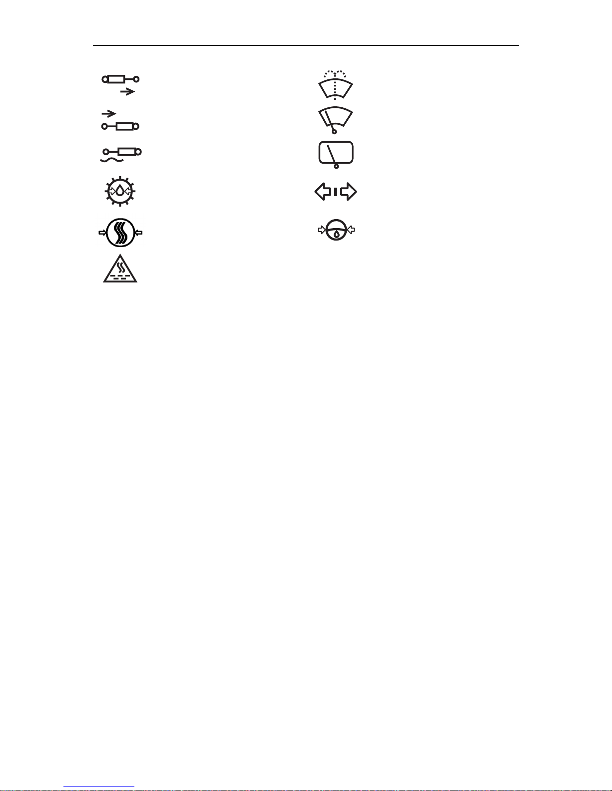
— control valve spool “lift” posi-
tion
— windshield washer
— control valve spool “drop”
position
— front windscreen wiper
— control valve spool “float”
position
— rear windscreen wiper
— oil pressure in gearbox
— trailer turning signal
— air pressure in pneumatic
system
— oil pressure in HPS
— air filter impurity
—
Page 8

MTZ 1220.1/1220.3 Section B. Safety requirements
B1
Section B. Safety Requirements
SAFETY REQUIREMENTS
Strict observance of safety precautions
and exact complying with the rules of
tractor control and its maintenance secure absolute safety of its operation.
General instructions
1. Study this operators manual atten-
tively before operating the tractor.
Poor knowledge of the tractor operation and service may lead to accidents.
2. Only specially trained and skilled
operators, who have passed accident-prevention and fire safety
briefings, are allowed to operate the
tractor.
3. If tractor is equipped with safety
belt use it during the operation. If
tractor is not equipped with safety
belt, contact the dealer.
4. Do not take a passenger into the
cab, if additional seat and hand
rails are not installed. There is no
any other safe space for a passenger in the cab!
5. Keep all warning plates clean.
6. Replace any damaged or missing
warning plate.
7. Carefully inspect the tractor, trailed
machine, mounted implement and
hitch before commencement of operations. Before starting operations
make sure that they are in good
order. Trailed agricultural machines
and transport trailers should have
rigid hitches, preventing their swaying and rear-end collision with the
tractor during a hauling.
Safety measures during tractor operation
Warning! Do not ever start the en-
gine while being outside the operator’s workplace. Always stay in the
cab in the operators seat when starting the engine or operating the controls.
7. Before starting the engine, make
sure that the parking brake is applied, the PTO control lever is in
«Disengaged» position, the gearshift and range selector levers are
in «Neutral» position. Make sure
the gearbox pump drive shifter is in
«Engine-Driven» position.
8. Always stay in the operators seat
when starting the engine or operating the controls.
9. Before starting motion, warn the
people around and those working
on the trailed machines with the
horn.
10. Do not leave the tractor in motion.
11. Before leaving the cab do not fail to
disengage the PTO, stop the engine, apply parking brake and remove the switch key.
12. Do not operate the tractor indoors
without proper ventilation. The exhaust gases may cause fatal outcome!
Page 9

MTZ-1221.2/1221В.2/1221.3 Safety requirements
11
13. Stop the tractor immediately if the
engine or steering system fails.
Remember, that with the engine
shut down you will have to apply
much more forces to the steering
wheel in order to control the tractor.
14. Do not work under raised agricultural implements. Do not leave
mounted implement in raised position during long-term stops.
15. If the tractor front part rises off the
ground when heavy implements are
mounted at the rear hitch linkage
mechanism, install the front ballast
weights.
16. When operating with front loader,
fill rear tires with liquid ballast and
adjust a maximum wheel turning
angle to 30° at the most.
17. Before lifting or lowering a mounted
agricultural implement, and when
turning, make sure in advance
there is no danger of contact with
anyone around or interference with
some obstacle.
18. During transportation with implements and accessories coupled,
mechanism for fixing of attached
parts in raised position must be
used (for HLL without hydraulically
operated lift).
19. Cardan shaft, transmitting rotation
from the tractor PTO to the implements of the unit, should be fitted
with appropriate guards.
20. Make sure of proper mounting of
any additional equipment or auxiliary device and make sure they
are designed for use with your tractor.
Bear in mind that your tractor, when
improperly employed, may be dangerous both for you and for the
people around. Do not use implements, which are not designed for
installation on this tractor.
21. To prevent tractor roll-over, be
careful during the driving the tractor. Select a safe speed, corresponding to the road conditions, especially during cross-country driving, driving over ditches, slopes and
sharp turns.
22. When working on hillsides, increase
tractor wheel tread to maximum
width.
23. Avoid making sharp turns at full
load and at high travel speed.
24. When using the tractor for hauling
operations, follow the rules:
• Increase wheel tread to 1600 mm
(64’’) at least;
• Interlock the brake pedals, check
and, if necessary, adjust the
brakes for simultaneous action;
• Check the parking brake performance;
• Check condition of the light and
audible signaling devices;
• Cargo trailers must be fitted with
rigid hitches as well as be connected with safety chain or rope;
• Never travel downhill “free wheel”
with transmission in neutral position or clutch disengaged. When
traveling downhill use the same
gear as you would when going
uphill;
• Never use a trailer without independent brakes, if its gross weight
exceeds the half of the tractor total
actual mass. The faster you move
and the more load you tow, the
longer safety distance must be;
• Disengage the FDA to avoid extensive wearing out of drive components and tires;
• Do not use the RADL at speed
exceeding 10 km/h and while turning.
• Do not stop the tractor on the
slopes. If it’s necessary to stop,
Page 10

MTZ-1221.2/1221В.2/1221.3 Safety requirements
12
engage the 1st gear and apply the
parking brake.
25. When you use PTO-driven equipment, stop the engine and make
sure that PTO drive end has
stopped completely, before you
leave the cab and uncouple the
equipment.
26. Do not wear loose clothes when
operating the PTO or when you are
in the vicinity of the rotating equipment.
27. When working with stationary machinery driven from the PTO, do not
fail to apply the parking brake and
block the rear wheels of the tractor
from the front and rear sides. Also
make sure the machine is secured
in its place.
28. Make sure the guard of the PTO
drive end is installed, and if the
PTO is not used, shift the PTO
mode control switch into midposition.
29. Do not carry out cleaning, adjustment and maintenance of the PTOdriven equipment when the engine
is running.
Safety measures during tractor
maintenance
30. Never refuel the tractor when the
engine is running.
31. Never smoke while refueling the
tractor.
32. Never fill the tank fully. Leave place
for fuel expansion.
33. Never add petrol or mixtures to the
diesel fuel. Such combinations may
enhance the fire or explosion hazard.
34. Use properly summer and winter
fuel grades. Fill in a fuel tank at the
end of each day to minimize night
water condensation.
35. Perform all operations, relating to
engine and tractor cleaning, prepa-
ration for work, maintenance, etc.,
when the engine is shut down and
brakes are applied.
36. The cooling system operates under
pressure, which is maintained by
the valve installed in the filler cap. It
is dangerous to remove the cap
when the engine is hot. To avoid
face and hands burns be careful
while opening radiator filler cap
when the engine is hot. Put close
cloth on the cap and take on a
glove in advance.
37. To avoid skin burns, be careful
when draining cooling liquid or water from the cooling system, hot oil
from the diesel, hydraulic system
and transmission.
38. Be careful when servicing storage
batteries, because electrolyte
causes burns if it comes into contact with the skin.
39. To avoid danger of explosion keep
any type of open flame away from
engine fuel system and storage batteries.
40. Keep the tractor, its equipment, especially brakes and steering control, in operable state in order to
ensure your own safety and safety
of people around.
41. Do not make any alternations in the
tractor or its separate components
without consulting your dealer and
or manufacturing works. Otherwise
the tractor will be deprived of aftersales service.
42. To avoid the fuel splash-out while
refueling the tractor by mechanized
method, remove the screen filter
from the fuel tank filler neck.
Screen filter is designed only for
manual refueling of the tractor in
the field.
43. Refuel the tractor using only oils
and lubricants recommended by the
manufacturing works. It is strictly
forbidden to use other lubricants!
Page 11

MTZ-1221.2/1221В.2/1221.3 Safety requirements
11
Safety requirements during
operation and maintenance of
electrical equipment
44. To avoid damaging the semiconductor devices and resistors,
comply with the following precautions:
• Do not disconnect the storage battery while the engine is running.
This will cause a peak voltage in
charging circuit and lead to immediate damage to the diodes and
transistors;
• Do not disconnect electric wires
until the engine is stopped and
electric switches are in the “OFF”
position;
• Do not cause a short circuit by the
wrong connection of electrical
wires. A short circuit or reverse
polarity will cause damage to the
diodes and transistors;
• Do not connect a storage battery
into the electrical equipment system until it has been checked for
correct voltage and terminals polarity;
• Do not check for current flow by
means of spark test as it will immediately result in transistors
breakdown;
• It is prohibited to switch off the
battery disconnect switch when
the engine is running;
• It is prohibited to operate the tractor without storage battery.
Hygienic requirements
• Daily fill the thermos with fresh
clean drinking water;
• First-aid kit should be completed
with bandages, iodine tincture, ammonia spirit, borated petrolatum, sodium
carbonate, menthol valerate and analgin;
• Use cab natural ventilation or cab
air heating and cooling unit according to
operation conditions.
• If the time of continuous tractor operation during a work shift exceeds 2,5
hours it’s necessary to use personal
noise protection equipment according
to GOST 12.4.051-87 (earplugs, antiphons).
Fire safety requirements
1. The tractor should be equipped with
firefighting equipment – shovel and
fire-extinguisher. It’s prohibited to
operate the tractor without fireextinguishing means.
2. Never refuel the tractor when the engine is running.
3. Do not smoke while refueling the
tractor.
4. Never fill the tank fully. Leave place
for fuel expansion.
5. Never add petrol or mixtures to the
diesel fuel. Such combinations may
enhance the fire or explosion hazard.
6. Places of tractors parking, storage of
fuel and lubrication materials should
be plowed around with a strip having
at least 3 m width and provided with
fire-extinguishing means.
7. Refuel the tractors with fuel and lubrication materials by mechanized
method with the engine shut down.
Use lighting at night. It is not recommended to fill in fuel tanks with the
help of buckets.
8. When performing repair operations in
the field with the application of electro-gas welding clean parts and assembly units from plant remains.
9. Prevent collector and muffler pollution with the dust, fuel, straw, etc.
10. Prevent straw reeling on the rotat-
ing parts of machines aggregated
with the tractor.
11. When washing parts and assembly
units with kerosene or gasoline take
Page 12

MTZ-1221.2/1221В.2/1221.3 Safety requirements
12
measures to prevent the flaming of
the washing liquid fumes.
12. Do not operate the tractor in the fire
dangerous areas when the bonnet
and other guard devices are taken
off the engine heated parts.
13. Do not use open fire for heating up
the oil in the engine pan, when filling in fuel tanks, and for burning off
the contaminant pollution of the radiator core.
14. When the fire seat occurs cover it
with sand or with canvas cloth or
other close cloth. Use the carbondioxide fire extinguisher. Do not extinguish burning fuel with water
15. See that there are no flammable
materials near exhaust manifold
and muffler when the engine is running.
Page 13
MTZ 1220.1/1220.3 Section С. Technical data
C1
Section C. TECHNICAL DATA
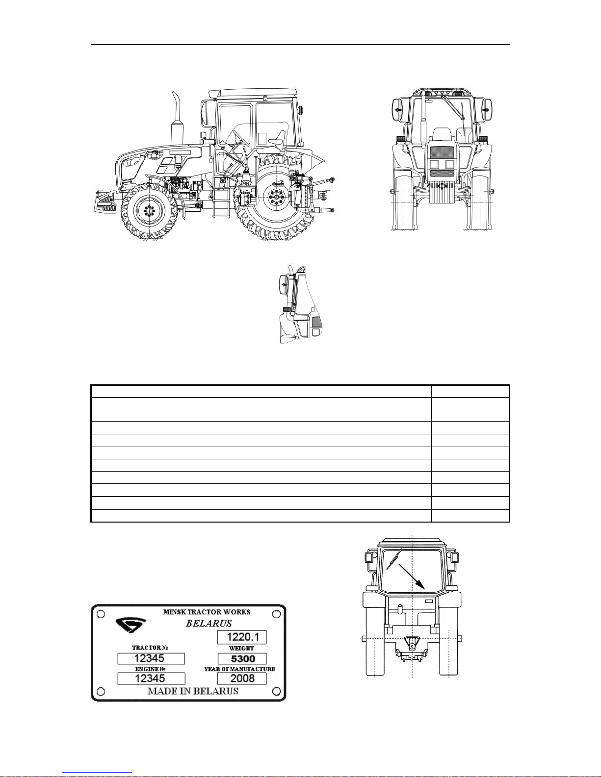
Tractor MTZ - 1220.1
Tractor MTZ - 1220.3
Muffler on the right side of cab column, for the rest see “MTZ - 1220.1”
Weights and dimension:
Parameter
Value
Length
with ballast weights and linkage to a tractor in transp
ort position
,
mm
4600±50
Width
over semiaxles ends
, mm
2250
±10
H
eight
over cab
, mm
2890
±50
Wheelbase
, mm
2550
±30
Agricultural clearance under axle tubes, mm
(not less than)
630
Road clearance
(
on tires of basic configuration
), mm, not less than
450
Tractor
structural weight
, kg
4850
±
100
Tractor operating we
ight, kg 5500
±
100
Tractor
maximum
operating
, kg 8800
Serial numbers of tractor constituents
Tractor identification plate indicates
tractor serial number and diesel engine
serial number.
Page 14
MTZ 1220.1/1220.3 Section С. Technical data
C2
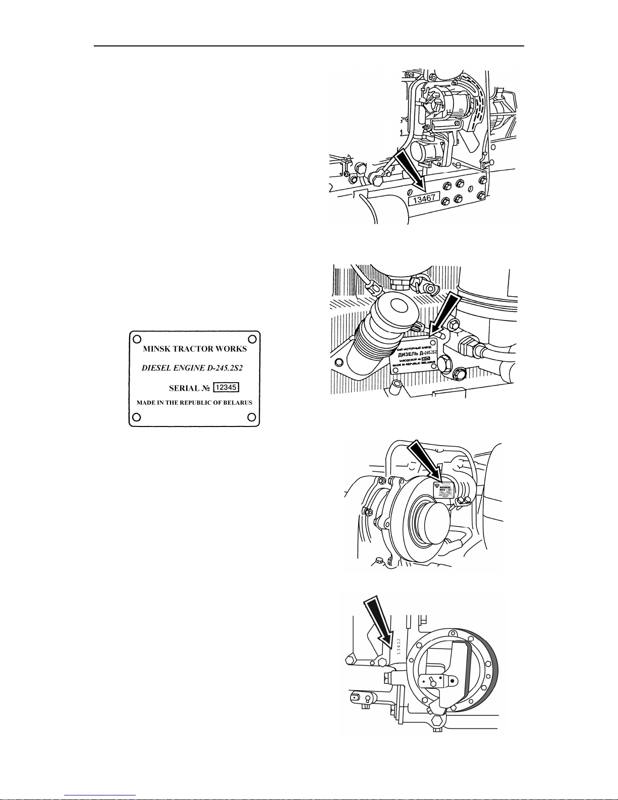
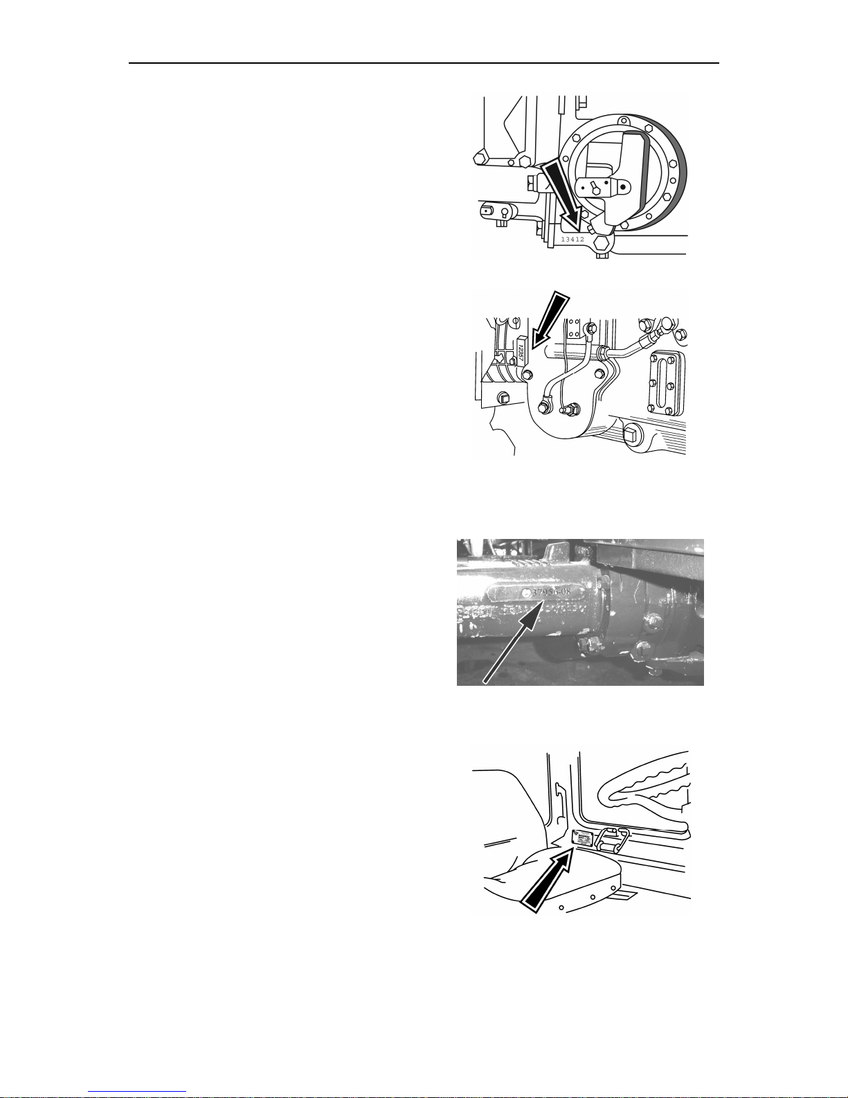
Tractor serial number is duplicated on
the right sidemember.
Diesel engine serial number is also indicated on the engine identification
plate located on the left side of cylinders block.
Diesel engine turbocharger identification number
Clutch coupling housing number
Page 15
MTZ 1220.1/1220.3 Section С. Technical data
C3
Gearbox identification number
.
Transmission identification number
Front driving axle identification number
Cab serial number
Page 16
MTZ 1220.1/1220.3 Section С. Technical data
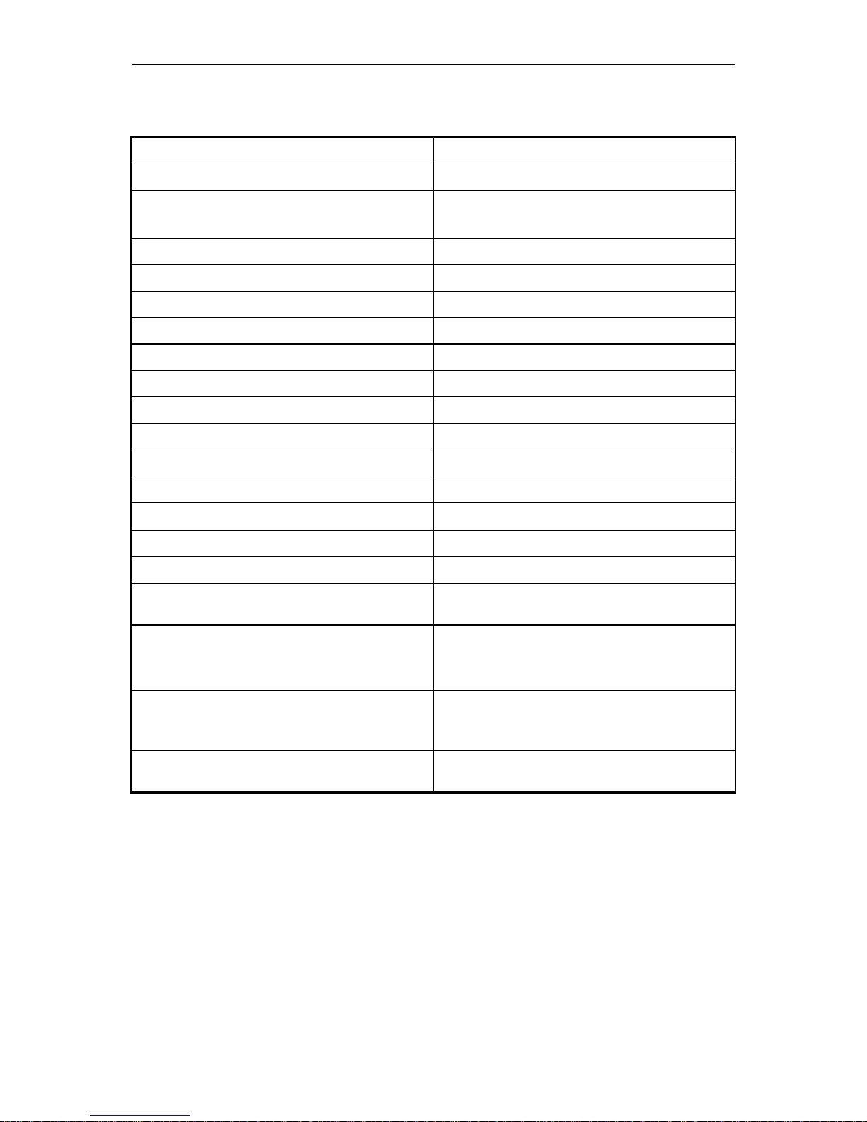
C4
Diesel engine
Engine model
D-245.2S2
Manufacturer
ОАО Minsk Motor Plant
Type
Four-cycle, turbo-charging with after-
cooling
Number of cylinders
4
Fuel injection system
direct injection
Compression ratio (calc
u
lated)
17±1
Cylinder bore
,
mm
110
Piston stroke
,
mm
125
Displacement
, l
4,75
Firing order
1-3-4-2
Cool
ing system
liquid
Rated speed
,
rev/min
2200
Maximum no
-
load speed
,
rev/min
2420
Minimum idle speed
,
rev/min
800±50
Rated power
, kW
90
Peak torque
, Nm
490
Specific fuel consumption at opera
t-
ing power, g/(kW·h)
254,0
7,12
1,5+−
Clearance b
etween rocker shaft
striker and intake valve stem end
when diesel engine is cold, mm
- 0,25
05,0
10,0+−
Clearance between rocker shaft
striker and exhaust valve stem end
when diesel engine is cold, mm
- 0,45
05,0
10,0+−
Fuel inje
ction lead angle
up to top
dead center (TDC), degrees
3,5±0,5
Page 17

MTZ 1220.1/1220.3 Section С. Technical data
C5
Diesel engine fuel system
Fuel pump
Type: four-plunger, in-line with priming
pump:
PP4M10Pli – 3704 (of the company
MOTORPAL, Czech Republic) or
773.1111005 –07 (of OAO YAZDA,
Russian Federation).
Regulator: mechanical, centrifugal, variable speed, direct acting type, with automatic fuel supply increase at engine
start.
Injectors: 455.1112010-50 or
172.1112010-11.01
Air cleaner
With paper filter elements.
Turbocharger
radial inward turbine and radial-flow
compressor, assembled on one shaft.
C14 type of the company CZ (“Turbo”),
Czech Republic. Installation of foreign
producers turbochargers is possible.
CAC
is of radiator type, installed in
front of water radiator. It is designed for
cooling of air charges inside the diesel
engine intake manifold.
Engine cooling system
Type: liquid, closed with positive liquid
circulation, temperature control, thermostatic regulator. Normal operating
temperature
from
85º to 95º.
Engine lubrication system
Тype: Combined, with oil-to-water heat
exchanger.
Oil purification: full-flow with exchangeable filter (indecomposable n-type)
Min oil pressure: 0.08 MPa at 600 rpm.
Working pressure between 0.25…0.35
MPa.
Max.pressure at cold engine: up to 0.6
MPa.
Engine Starting System
24 V starting motor, rated power 4.0kW
or 4.5 kW
Starting aid:
Heating plugs, rated voltage 23V or
11V.
Generator
AC, rated voltage 14V, power 1.15 kW.
Clutch coupling
Type: Dry friction, double-disk
spring loaded clutch
Page 18
MTZ 1220.1/1220.3 Section С. Technical data
C6
Gear box
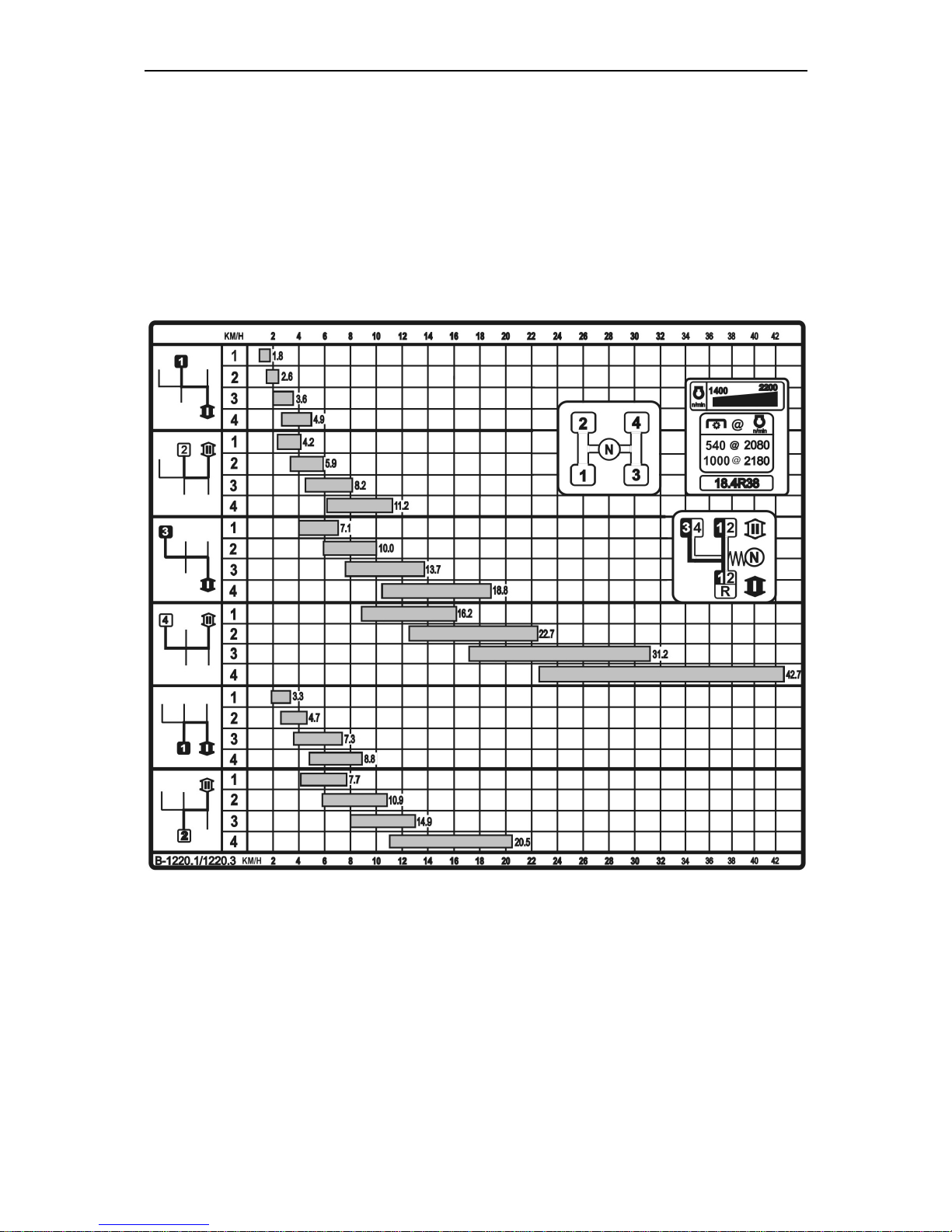
Type: 16/8, mechanical, step-by-step, ranged with constant-mesh gears. Shifting of
four gears in each range of forward and reverse movement is carried out via synchronizers.
The Table below is placed in the right part of the cab window,
Note – A gearbox 24/12 can be installed in your tractor optionally. In this case a Table with corresponding series of speeds will be in the cab window.
Tractor design travel speeds with rear wheels 18.4R38
Rear axle
Main gear: a pair of bevel gears with
spiral tooth.
Final drives: a pair of spur gears for
each sideboard.
Rear-axle drives: planetary type.
Page 19

MTZ 1220.1/1220.3 Section С. Technical data
C7
Differential lock: Oil-actuated friction
clutch
Brakes
Service Brakes: on rear wheels: twodisk or three-disk, dry with mechanical
servo drive. Disk diameter: 204 mm (or
eight-disk, operating in oil sump (option)
Parking brake: On rear wheels through
differential lock on final drives and rearaxle drives. Dry-disk type with mechanical hand control. Disk diameter: 180
mm (or 4-disk, operating in oil sump
(option))
Front driving axle
Type: two-point, beam-type
Main gear type: bevel gears with spiral
tooth.
Differential type: self-locking, exces-
sive friction
Final gears type: planetary
Drive gear type: built in GB single pa-
rallel-shaft reduction gear unit with hydraulically operated multiplate clutch;
cardan shaft.
Hydraulic distributor of FDA control:
hydraulically operated, spool-type, electrically controlled
PTO drive
Type: independent, two-speed and
synchronous
Drive clutch: Planetary reduction gear
with band brakes
Drive: electrohydraulic
PTO end speed:
Independent drive
I — 540 rpm; N=60 kW,
II — 1000 rpm; N=90 kW.
Synchronous drive
4,18 rev/meter of travel when fitted with
tires 18,4R38.
PTO shaft end extension: SAE standard 6-spline for 540 rpm and 21-spline
for 1000 rpm.
Rotation: Clockwise
Steering
Type: hydrostatic (H.S.).
Feed pump: NSH14, gear-type, left-
handed rotation.
Volume constant — 14 m3/rev.
Metering pump type — gerotor type
Volume constant – 160 m3/rev.
Relief valve pressure— 14 Pa (140
kgf/m2).
Antishock valves pressure — 20 Pa
(200 kgf/m2).
Actuating mechanism: one hydraulic
bilateral cylinders.
Bore — 63 mm,
Cylinder stroke— 200 mm
Steering wheel range of adjustment:
• in angle of slope - from 25° to 40°
with fixation in four positions,
• in height – along steering shaft axle,
stepless 100 ±200 mm
Backlash in the steering wheel –
max. 25°, when feed pump is in opera-
tion
Hydraulic lift linkage (HLL)
Type: unit-principle with hydraulic lift
device (with two plunger cylinders) It
Page 20

MTZ 1220.1/1220.3 Section С. Technical data
C8
provides 4 control modes of agricultural
implements position:
• height control mode;
• power control mode;
• position control mode;
• combined (mixed) control mode.
Outlets: 3 pairs and one drain line
(rear).
Oil feed pump
Тype: gear-type. Pump capacity — not
less than 56 l/min at 2100 rpm.
Distributive valve: hydraulic spooltype 70-1221 or RS-213 «MITA», 3section with fixation of spools in “float”
position. It has the following positions:
“Up”, “Neutral”, “Down” and “Float”.
Hydraulic lift distributor:
820-4634010. hydraulic spool distributor
Cylinder: piston cylinder
(2 pcs.) — bore 90 mm,
stroke — 220 mm.
Rear lift linkage:
Type: swinging four-bar linkage of cat-
egory II
Lifting capacity of rear lift linkage on
suspension axis is not less than 4500
kg.
Electrical equipment
Voltage of on-board power system:
12V
Power system: two accumulator batte-
ries12 V each, with capacity 88 •h or
90 •h .
Lighting and light alarm system:
• front driving lights with high/low
beam;
• front and rear work lights;
• front and rear lamps;
• dash board light and rear registration
plate light;
• hazard warning lights;
• lights of “road-train” sign (optional).
Power consumers connection: multipin composite plug.
Test instruments
Instrument cluster, integrated display
and control lamps blocks.
Other equipment:
Front and rear window wipers; windshield washer; dome light.
Pneumatic system
Compressor
Type: single-cylinder, air-cooled
Trailer brakes control
Type: pneumatic, single-wire, locked
with tractor service brakes (option –
two-wire).
Wheels
Tyres (main modification)
Front:
M 420/70R24 or 14,9R24;
On order: 11.2R24.
Rear:
Main: 18,4R38;
On order: 16.9R38, 11.2R42.
Wheel Track:
• front wheel track 1535, 1635, 1700,
1800, 1850, mm, 1950; 2020; 2120.
• rear wheel track 1450...2200 mm.
Page 21
MTZ 1220.1/1220.3 Section D . Operation controls and instruments
D1
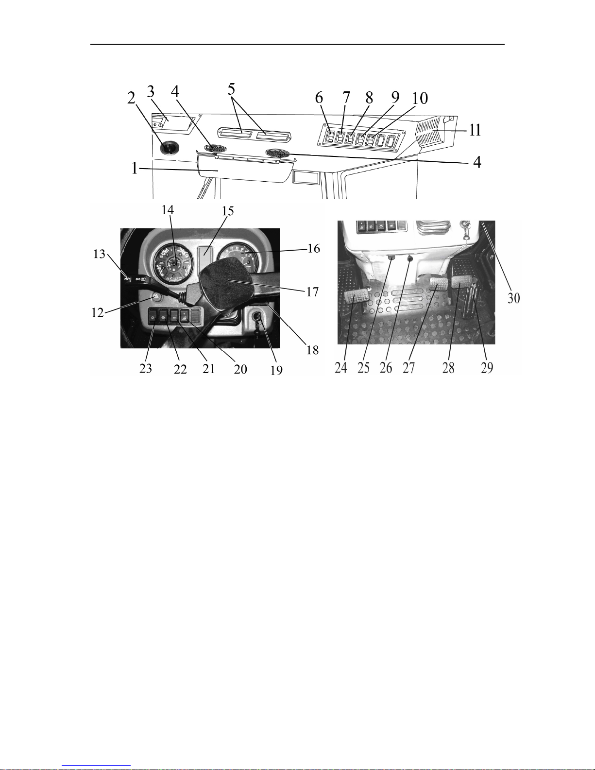
Section D. OPERATION CONTROLS AND INSTRUMENTS
1. Sunscreen;
2. Heater control valve operating handle;
3. Radio-receiving set (if any);
4. Air distributors of cab ventilation and heating system;
5. Recirculation shutters;
6. Front windscreen wiper switch;
7. Cab fan and heater switch;
8. Rear working lights switch;
9. Front working lights switch;
10. Road-train sign lighting switch;
11. Cab light switch;
12. Emergency control lamps switch;
13. Steering-wheel-mounted multifunction
switch (turn, turn indicators, upper/lower
beam);
14. Instrument cluster;
15. Control lamps block;
16. Integrated indicator;
17. Steering wheel;
18. Integrated indicator program console;
19. Starter and instruments switch;
20. Front working lights switch on cab grabhandles;
21. AB remote cut-off;
22. Windscreen washer switch;
23. Main light switch;
24. Clutch pedal;
25. Diesel engine stop lever;
26. Steering column inclination control;
27. Brake pedal
28. Right brake pedal
29. Fuel feed control pedal
30. Hydraulic output control levers
Page 22
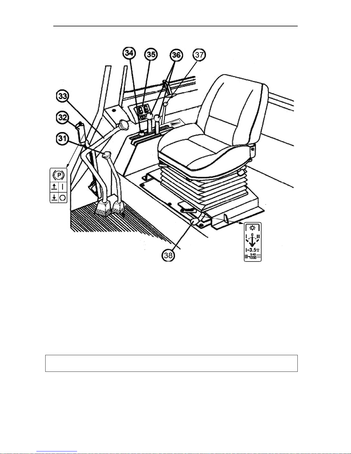
MTZ 1220.1/1220.3 Section D . Operation controls and instruments
D2
31. GB range selector lever;
32. Parking brake lever;
33. Gear-change lever;
34. Governor control lever stop bumper
;
35. FDA, rear axle differential lock and PTO
control arm;
36. Tillage depth adjustment levers
37. Fuel feed control lever
38 Power take-off shifter arm (independent
- synchronous)
Important: Before starting tractor operation study the purposes for which the controls,
instruments and functions may be applied.
The given information will facilitate studying of controls and instruments for tractor safe
operation.
Page 23
MTZ 1220.1/1220.3 Section D . Operation controls and instruments
D3
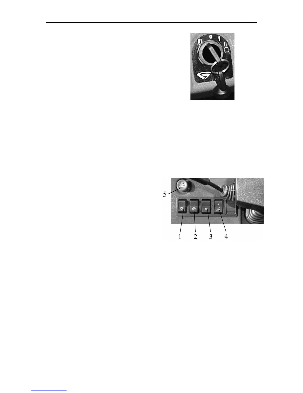
Starter and instrumentation switch
Switch (1) has four positions:
• 0 – “Off”;
• I –"Instruments, control lamps block,
heating plugs are on”;
• II – “Starter On” (not fixed position);
• III – “Radio receiver ON” (key is turned
counter-clockwise).
IMPORTANT! Starter restarting may be
possible "0”.
In order to shift starter and instruments
switch into position “III’, it it necessary to
sunk the key into switch slightly and then
turn it counterclockwise.
Instrument board switches
1 – main light switch, has three positions:
- “Off” (upper part of the button is sunk,
position I);
- “Front and rear marking lights, numberplate light, board gauges light, and additional
lamps on the trailed machine are on” (middle
position, II);
- “All consumers of position II and road
lamps are on” (lower part of the button is
pressed up to the stop, position III).
2 – windscreen washer switch.
Windscreen washer is switched on by single pressing to the button.
3 – remote AB switch. AB is switched by
single pressing to the remote AB switch button, and it is switched off by pressing the
same button again.
4 – shut-off switch for front working
lights, installed on front light brackets. By
pressing button 8 two working lamps, (installed on front light brackets) and indicator
light, built-in the button.
By pressing the emergency light alarm button 5 the emergency light alarm is engaged.
The indicating lamp blinks simultaneously with
alarm flashing light. Emergency light alarm is
disengaged by pressing the same button
again.
1 - main light switch; 2 - windscreen washer
switch; 3 - remote AB switch; 4 - shut-off switch
for front working lights, installed on front light
brackets.
Page 24
MTZ 1220.1/1220.3 Section D . Operation controls and instruments
D4
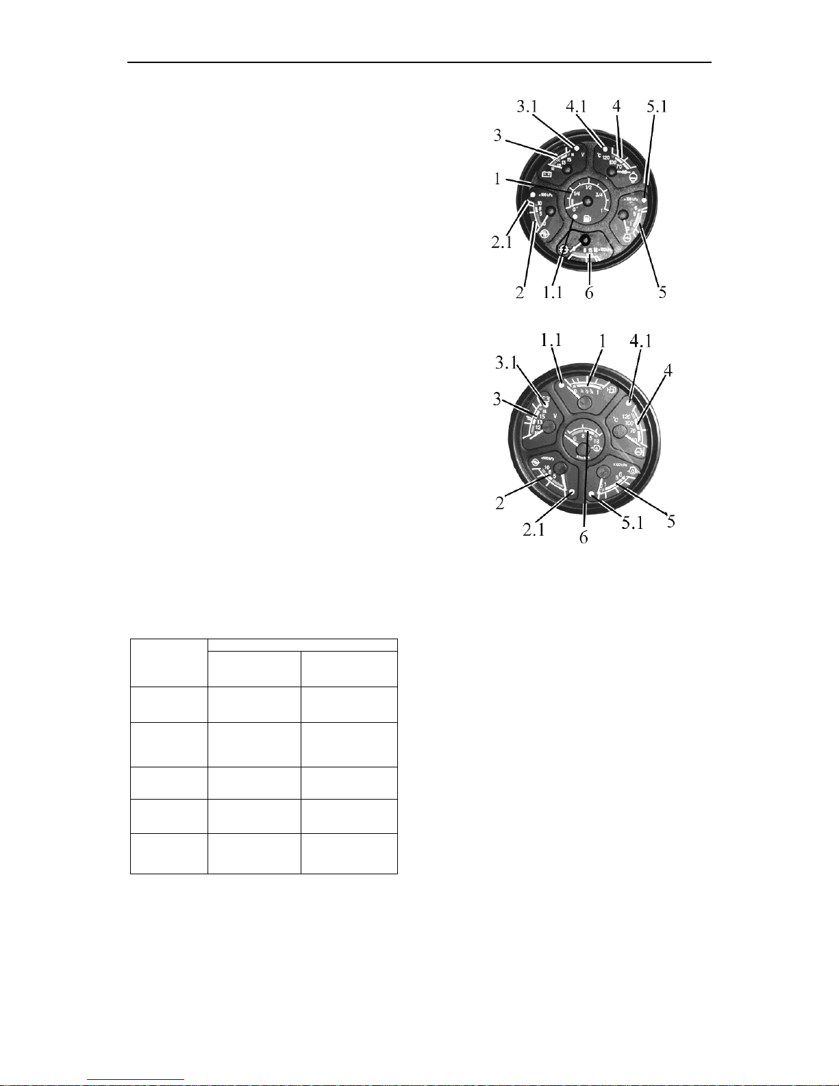
Instrument cluster
Instrument cluster includes six gauges with
five signal lamps.
Scale indicating fuel volume in the tank (1)
has divisions 0–1/4–1/2–3/4–1. A signal lamp
(1.1) (orange color) is built in the gauge scale,
which lights up when fuel volume in the tank
drops below 1/8 of the total tank volume.
ATTENTION: do not let the tank become em
p-
ty (the gauge pointer is in the zone of orange co
l-
or)!
Scale indicating air pressure in pneumatic
system (2) has three divisions:
- working – from 500 from 800 kPa (green);
- emergency (two) — from 0 to 500 kPa and
from 800 to 1000 kPa (red).
A signal lamp (2.1) (red), is built in the
gauge scale, which lights up when the pressure in pneumatic system loss reaches 500
kPa.
Voltage gauge
(3)
indicates accumulator
batteries voltage with the engine stopped
when the key of starter and instruments
switch
(1)
is set in position “I”. With the engine running the voltage gauge indicates
voltage on generator terminals. An indicating lamp
(3.1)
of red color is built in the
scale of voltage gauge. It is used only with
24V starting system. It indicates the
process of the additional battery charge
with 24V – it checks the workability of the
voltage converter.
Zone on the
voltage
gauge scale,
color
States of powe
r supply system
with the engine
running
with the engine
stopped
13,0 – 15,0 V
green
normal mode of
charge
10,0 – 12,0 V
red
the generator is
out of order
accumulator ba
t-
tery
discharged
12,0 – 13,0 V
yellow
No AB charge
(low charging voltage)
AB has a normal
charge
15,0 – 16,0 V
red
AB recharge
white line in
the yellow
zone
Rated AB electromotive force is
12,7 V
IMPORTANT!
if the voltage gauge
(3)
indicates absence of AB charge, check the
state and tension of the generator drive
belt
.
ATTENTION
! When
emergency temperature indicating lamp or emergency oil pressure in the diesel engine indicating lamp is
Variant 1
Variant 2
Scale indicating diesel engine coolant tem-
perature (4) has three zones:
- engine warm-up — 40 - 70°, yellow;
- working — from 70 to 100° - green;
- emergency — from 100 to 120° - red.
Emergency engine coolant temperature indicator
lamp becomes on when coolant temperature exceeds
105 °.
Scale of oil pressure gauge in the engine
lubricating system (5) has three zones:
- working — from 100 to 500 kPa - green;
- emergency (two) — from 0 to 100 kPa and
from 500 to 600 kPa (red);
Indicator lamp 5.1 “Emergency oil pressure in the
engine” responses at values of 100 kPa and less.
IMPORTANT! when the cold engine is started the
pressure can be 600 kPa and higher.
Scale of oil pressure gauge in the transmis-
sion hydraulic system
(6)
has three zones
:
-
working — from
800
to
1500
kPa
-
green
;
-
emergency (two
) —
from 0 to
800
kPa
and
from 1500 to 1800
kPa
- red.
Page 25

MTZ 1220.1/1220.3 Section D . Operation controls and instruments
D5
on
, stop the engine, find and eliminate fai
l-
ure!
Page 26
MTZ 1220.1/1220.3 Section D . Operation controls and instruments
D6
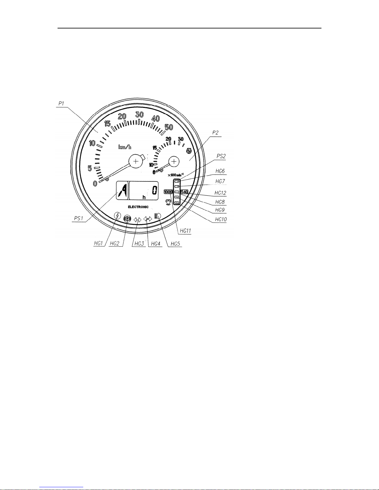
Integrated indicator
АР80.3813 (1)
Integrated indicator (hereinafter referred to as II) and control console (hereinafter referred to as CC) controls operational parameters of systems and assembly units of tractors “MTZ” and deliver data on malfunctions or failures of a system to the operator.
The ID includes indicators
and pilot lights, recording
the following parameters:
1 – Speed indicator
(pointer indicator));
2 – Engine rotational
speed indicator (pointer
indicator);
S1 – Liquid crystal display, multifunction display
(detailed description and
operation principle; S1
see. below)
S2 – PTO rotations indi-
cator (indicator lamp);
HG1 – Alarm of the overvoltage in the tractor on-board power system (red);
HG2 – Parking break engagement indicating lamp (red);
HG3 – Tractor turn indicator pilot lamp (green);
HG4 – Trailer turn indicator pilot lamp (green);
HG5 – Upper beam switching on indicator (blue);
HG6, HG10 – PTO speed scale segments (yellow);
HG7… HG9 – PTO speed scale segments (green);
HG11, HG12 – PTO speed scale range signaling devices (yellow);
Principle of operation and purpose of indicators on integrated indicator.
1 – speed indicator - shows travel speed of the tractor in graph form.
The indicator is operated by signals from pulse transducers of toothed gears speed of
final drives of tractor’s left and right rear wheels. Speed is indicated by the signal from the
Page 27

MTZ 1220.1/1220.3 Section D . Operation controls and instruments
D7
transducer installed on the final drive gear of the wheel rotating with the lowest speed. In case
of absence of a signal, there will not be any speed readouts (see below for more details).
Readouts range from 0 to 50 km/h.
Р2 – engine rpm indicator – shows engine shaft speed of the tractor in graph form.
The indicator is operated by a signal from generator phase winding.
Engine rpm range from 0 to 3500 (rpm).
РS2 – PTO speed indicator – shows power take-off shaft rpm on the light indicator.
The PTO speed indicator operates from a frequency signal produced by recalculation from the engine speed with an input value of the “KV2” ratio (see below) different
from “0”, herewith a value of the ZV ratio equal to “0” must be input (see below).
When the II is on (check of the device operability is described below) and the engine is running (a message of “engine speed” is transmitted from the ECU), the designations of the “540” and “1000” scales are illuminated simultaneously.
Informative:
the lower segment of the PTO scale (with consideration to the “KV2” ratio) is indicated when the engine speed achieves 1400-1500 rpm or higher.
Depending on the engaged PTO speed mode (540 or 1000), the illuminated scale segments designate PTO speeds as specified in Table 3.
Table 1.1
Values of scale segments
response “1000” (rpm)
Location of the segment in
the scale
Values of scale segments
response “540” (rpm)
1150 HG6 650
1050 HG7 580
950 HG8 500
850 HG9 420
750 HG10 320
РS1- multifunctional display (MD) is an LCD displaying:
1. digital designation of the gearbox shifter
(figures of 0 to 6) or a letter designation of
the reducer shifter position (letters L, M, H,
N).
2. current numerical value of one of the para-
meters of the tractor systems.
The integrated display receives information about the gearbox shifter position from the
transmission control unit (if the complex electronic control system is available) or from
the range reducer control unit (if available). This parameter is displayed in the “1” informative field (Figure 1.6). When control units are not available or are not connected, or a
wire is broken, the “1” informative field displays an “A” letter.
The “2” informative field displays the following parameters:
Page 28
MTZ 1220.1/1220.3 Section D . Operation controls and instruments
D8
1. Total astronomical service hours of the engine.
The counter operates with the engine running.
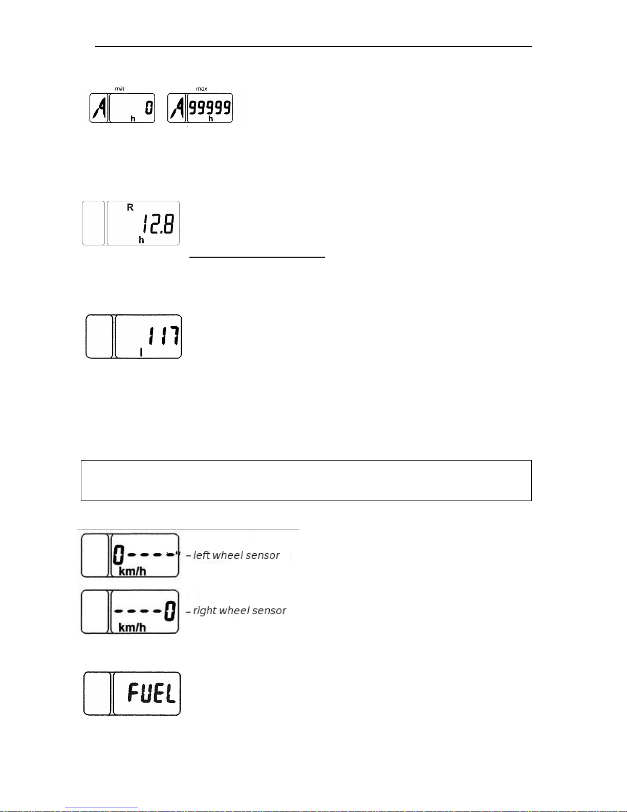
The indication range is 0 to 99999 service hours of the
engine.
In case of power supply interruption the counter saves the information on total service
hours.
2. Service hours over the set period:
In this mode astronomical service hours of the engine is displayed
over the set period of time passed from the previous setting of the
parameter to zero.
Setting to zero algorithm includes choosing of a specified mode,
pushing and holding for seconds of “Mode” key until the counter readouts are set to “0”.
3. Volume of fuel remaining:
In this mode, the current fuel volume in the tank is displayed in
liters.
This mode is available only when the tractor stands still.
Note – tractors “MTZ-220.1/1220.3” are equipped with two fuel volume sensors:
- there is one frequency fuel volume sensor (FFVS) inside a fuel tank under a cab.
- there is another modified frequency fuel volume sensor (MFFVS) inside a fuel tank on a
frame.
Data on total volume of fuel in the fuel tanks comes from a MFFVS to an indica-
tor.
NOTE. Switching between display modes “Total astronomical service hours of the
engine” and “Volume of fuel remaining“ is shall be carried out by “Mode” key on the
control console (2).
3. Diagnostics of speed sensor operability and connection:
When no signal arrives from the speed
sensors for 10 to 12 seconds, the LCD
screen shows a message of a “0” figure
specifying the location of the faulty sensor
(left or right).
4. Diagnostics of frequency-type fuel volume sensor operability (FFVS):
When no frequency signal arrives from the FFVS for 2 seconds,
the LCD screen of the II shows a “FUEL” message;
Page 29
MTZ 1220.1/1220.3 Section D . Operation controls and instruments
D9
Each failure message (Example: 0----, FUEL, C-BUS) is displayed on the LCD
screen by priority independently of the information displayed. Sequentially pressing the
“Mode” button must browse through the messages alternately. When the last message
is shown and the “Mode” button is pressed again, the LCD screen switches to the display mode as per the cycle of the previously specified working parameters.
Failure messages are displayed on the LCD screen each time the device is turned on,
till the reason of the failure is eliminated.
IMPORTANT: When the II is turned on, the MD shows information in the indication
mode that had been selected before the II was turned off last time.
Indicating lamp operation principles
HG1 – tractor on-board circuit high voltage indicator. Goes on when the tractor electrical
system supply voltage exceeds 19 V and goes off when the supply voltage is reduced to
17 V;
Herewith, the II is completely turned off and restores its operability when the vol-
tage drops to the rated voltage of the on-board circuit
HG2 – parking brake engagement indicator:
The parking brake indicator blinks with the frequency of 1 Hz when the parking
brake sensor goes off;
HG3, HG4 – tractor and trailer turn indicator.
Blinks when the right or left turn indicator is turned on by the under steering multi-
functional switch 14 or when the alarm signaling switch is turned on.
HG5 – headlight upper beam indicator pilot lamp. Goes on when the upper beam indica-
tor pilot lamp is switched on.
Note
!
Indicators are switched on and off synchronous with changes of system sen-
sors state.
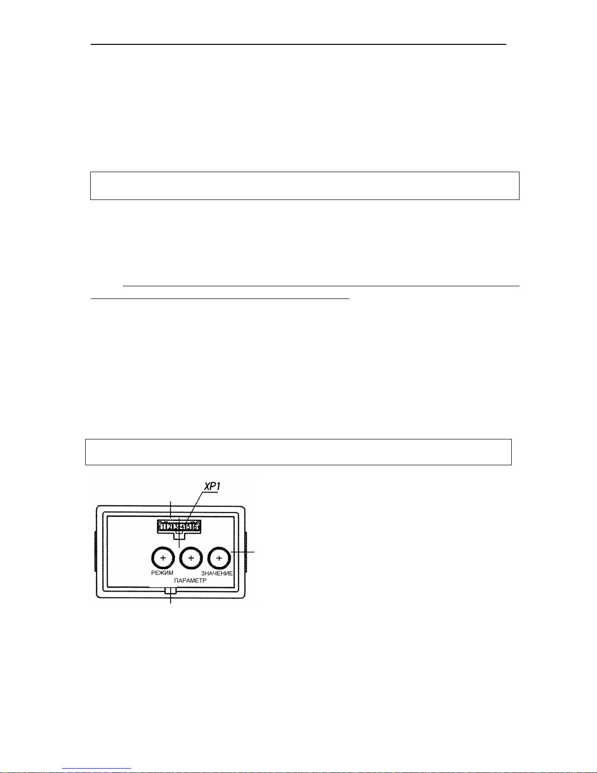
Integrated indicator control console АР80.3709
(2). II programming.
The programming console allows for manually programming the indicator with the “Parameter” and
“Value” buttons, changing the display mode of parameters shown on the LCD.
The front face of the console has a diagnostic socket
ХР1 that allows for automatic programming (repro-
gramming) the ID with a special device (if available). If
no special device is available, reprogramming is per-
formed with the above mentioned buttons.
II programming algorithm is as follows:
1. When the “Parameter” button is pressed for the first time, the LCD switches to the
mode of viewing the programmed parameter and its numerical value. When the button
is pressed repeatedly, the parameters are alternated cyclically.
Page 30
MTZ 1220.1/1220.3 Section D . Operation controls and instruments
D10
2. When the “Value” button is pressed repeatedly, the numerical value of the set programmed parameter is changed.
3. When neither the “Parameter” nor “Value” button is pressed for 7.0 seconds, the
mode is exited automatically.
When exiting the mode, the parameter values selected with the “Value” button are
stored.
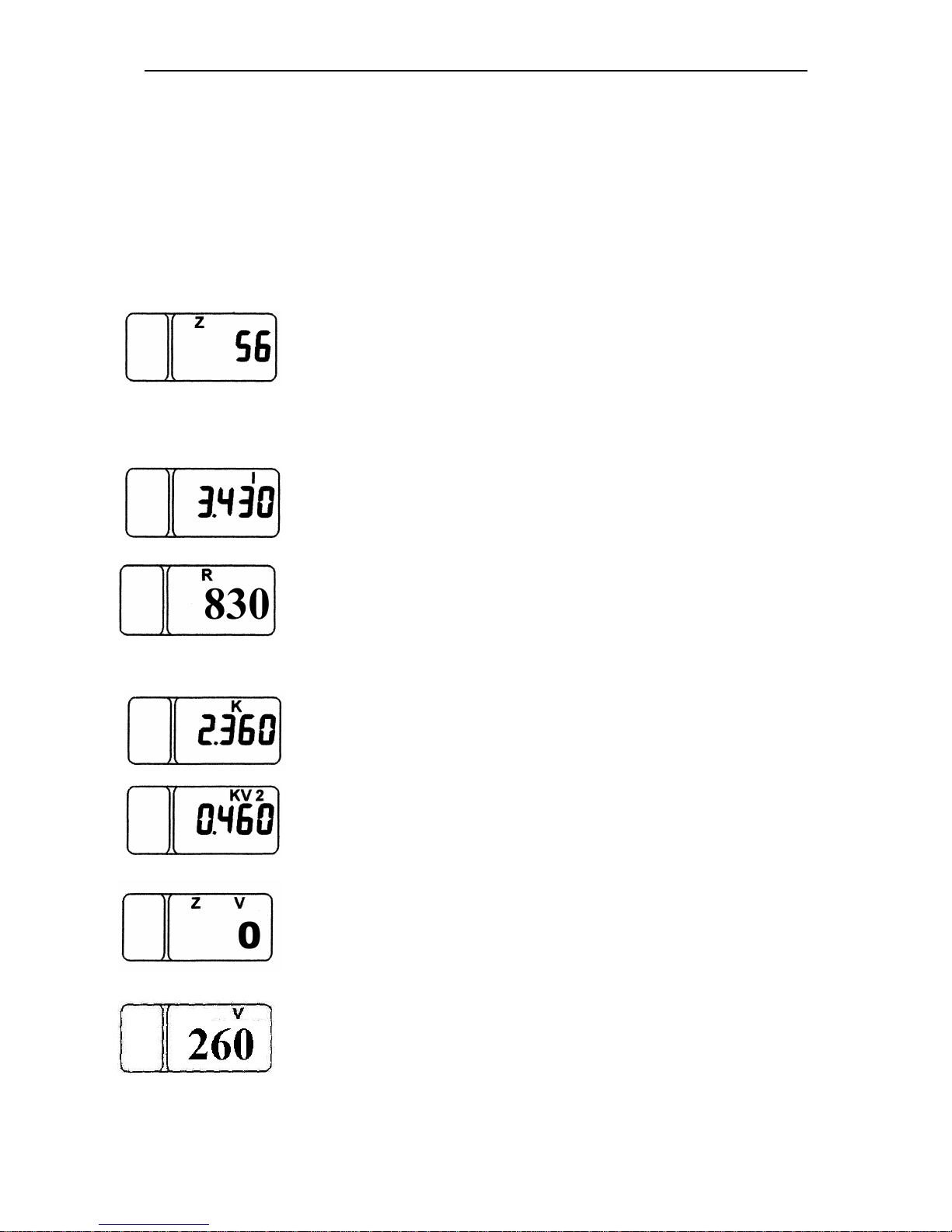
List of programmed ratios(graphic examples of parameter presentations and their values in the programming mode):
“Z” parameter
Z is the number of teeth of final shaft gears of the driving wheels
(right and left), at which the travel speed (rotation speed) sensors
are installed.
.
“I” parameter
I is the gear ratio multiplier of the wheel-hub drive;
“R” parameter
R is the rear wheel rolling radius, mm (is the value for tires
18.4R38. If other tire types are installed, set the “R” value corresponding to the rolling radius of the installed tires);
“” parameter
K is f generator drive transfer ratio;
“KV2” parameter
KV2 is the PTO gear ratio;
“ZV” parameter
ZV is the teeth number of the PTO speed sensor gear;
“V” parameter
V is the fuel tank volume, (l).
Page 31

MTZ 1220.1/1220.3 Section D . Operation controls and instruments
D11
Also, when the “Parameter” button is pressed in the programming
mode, the list of programmed parameters contains an independent
“T” parameter of precise readout of the astronomic service hours
of the engine. This parameter cannot be modified, it is the precise
number (to 1/10 of an hour) of engine service hours.
Attention!
1. During operation, it is allowed to modify the value of the parameters
- “wheel rolling radius R” which is determined based on the tires installed on the tractor by measuring the distance from the wheel center to the reference surface.
2. You mustn’t modify the entered values of all other parameters!
When the instrument scale illumination is on (position II “Instrument panel illumination, parking lights ON” and position III “Consumers of the position II, front headlights,
and parking lights ON”) the brightness of the MD screen of the PTO indicator segments
is automatically reduced.
IMPORTANT
!
Upon each connection to a power supply In II check of point indicators
and PTO shaft indicator scale segments functions is carried out. At this time the pointers deviate from start marks and appear to come over the first digitized scale marks
(over “5” for speed and over “10” for rpm), and all PTO scale’s segments and symbols “540’ and “000” .
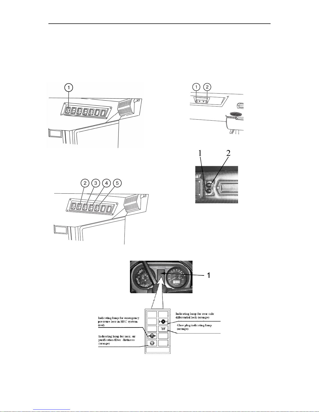
Windscreen washer switch (1)
When the key (1) is pressed the
windscreen washer is turned on.
Cab fan and heater switch (2)
After pressing button (2) a fan of cab
heating and ventilating system is on.
Switch has 3 positions:
1 – “Switched off” (top of the button is sunk
as much as possible);
2 – “Mode of light air feed is engaged”,
3 – “Mode of coarse air feed is engaged”.
Rear working lights switch (3)
After pressing button (3) rear working
lights and indicator light, built-in the button are on.
Front working lights switch (4)
After pressing button (4) front working
lights and indicator light, built-in the button are on.
Road-train sign lighting switch (5)
After pressing button (5) three orange
lamps, installed on the front part of a cab
roof and indicator light, built-in the button,
are on.
Radio switch (if any)
1. – Volume of sound switching on/off;
2. – Radio tuning
Note: Radio can only be switched on in
positions I or III of the starter switch key.
Page 32
MTZ 1220.1/1220.3 Section D . Operation controls and instruments
D12
Air-conditioner control (if it is installed instead of fan-heater)
Climatic installation control console has
switches (1) and (2).
1 – Air flow adjustment switch;
2 – Air-conditioner switch and refrigerating output adjustment.
Indicating lamp block (1)
Fuses
Page 33
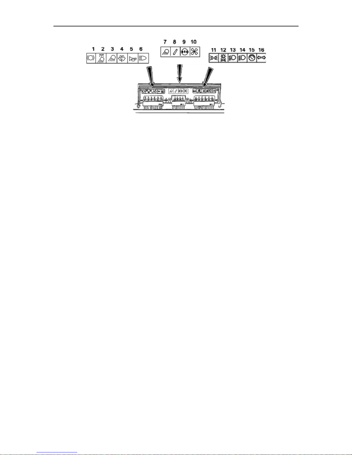
MTZ 1220.1/1220.3 Section D . Operation controls and instruments
D13
Three electrical circuit fuse blocks are
mounted inside an instrument board. In order to access the fuses unscrew 2 screws
and open instrument board cover.
Sixteen fuses protect the following tractor electric circuits from overloads:
1. Stop signal (15 );
2. Cab dome light, rear working lights
and road-train sign lamps (15 );
3. Emergency alarm lamp (15 );
4. Front and rear windows wipers and
windscreen washer (25 );
5. Audible alarm (15 );
6. Working headlight (25 );
7. Front working lights (25 );
8. Fan-heater, PTO shaft control systems, rear axle differential lock engagement system and FDA drive control system (25 );
9. Power supply to consumers, working
after switching the starter and instruments into position “I” (25 )
10. Air-conditioner control (if installed
optionally instead of heater fan) (25 ).
11. Left marker lights (7,5 );
12. Right marker lights and instrument
board highlighting (15 );
13. Left road lamp lower beam (7,5 );
14. Right road lamp lower beam (7,5
);
15. Instruments, speed sensors power
supply (7,5 );
16. Turn signal relay, qlow plugs block
power supply, qlow plug relay winding
(15 )
Page 34
MTZ 1220.1/1220.3 Section D . Operation controls and instruments
D14
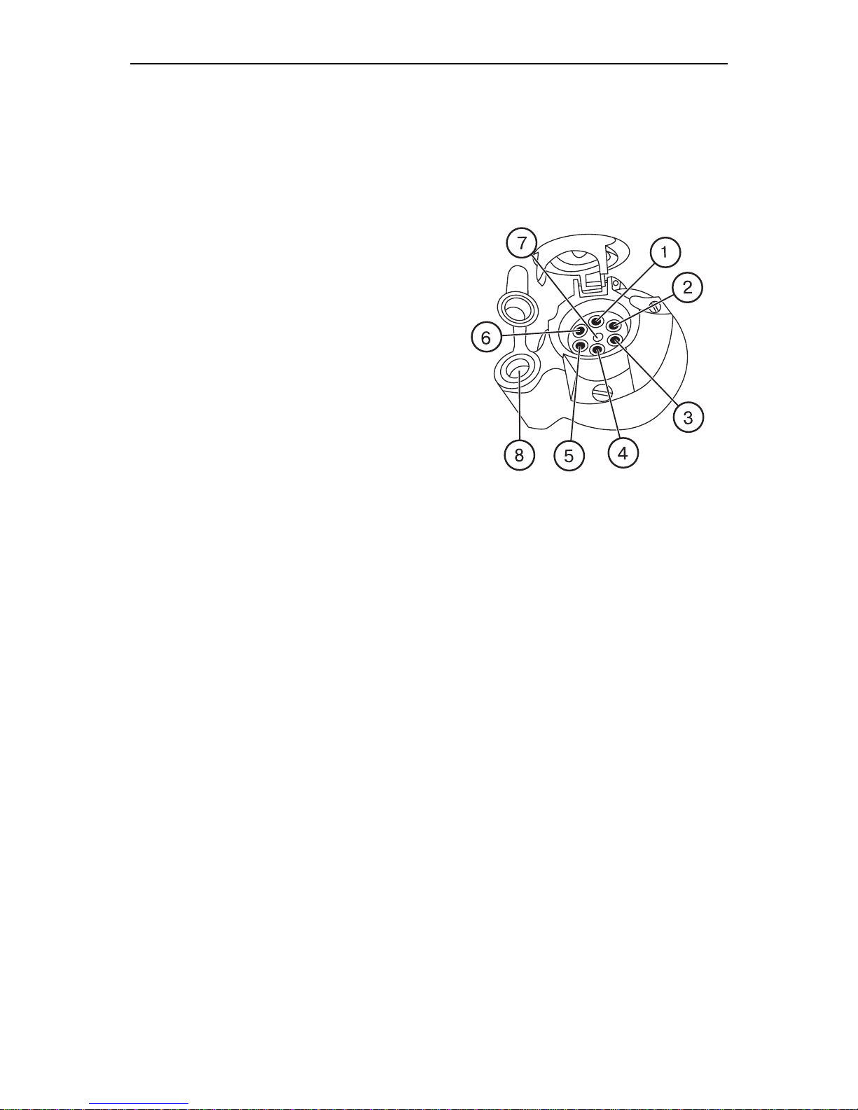
Electric equipment connector components
A combined multipin socket is designed
for connecting the trailer electrical
equipment or electrical equipment of
trailed agricultural implement and service lamp. It is installed on the cab’s
rear support. A plug of the wire bundle
of the hitched machines and a plug of
service lamp are connected to the
socket.
Socket connection terminal marking:
1 – Turn indicator, left;
2 – Horn;
3 – “Ground”;
4 – Turn indicator, right;
5 – Right clearance light;
6 – Stop light;
7 – Left clearance light;
8 – Female connector for service lamp or
other consumer (up to 8A).
Page 35
MTZ 1220.1/1220.3 Section D . Operation controls and instruments
D15
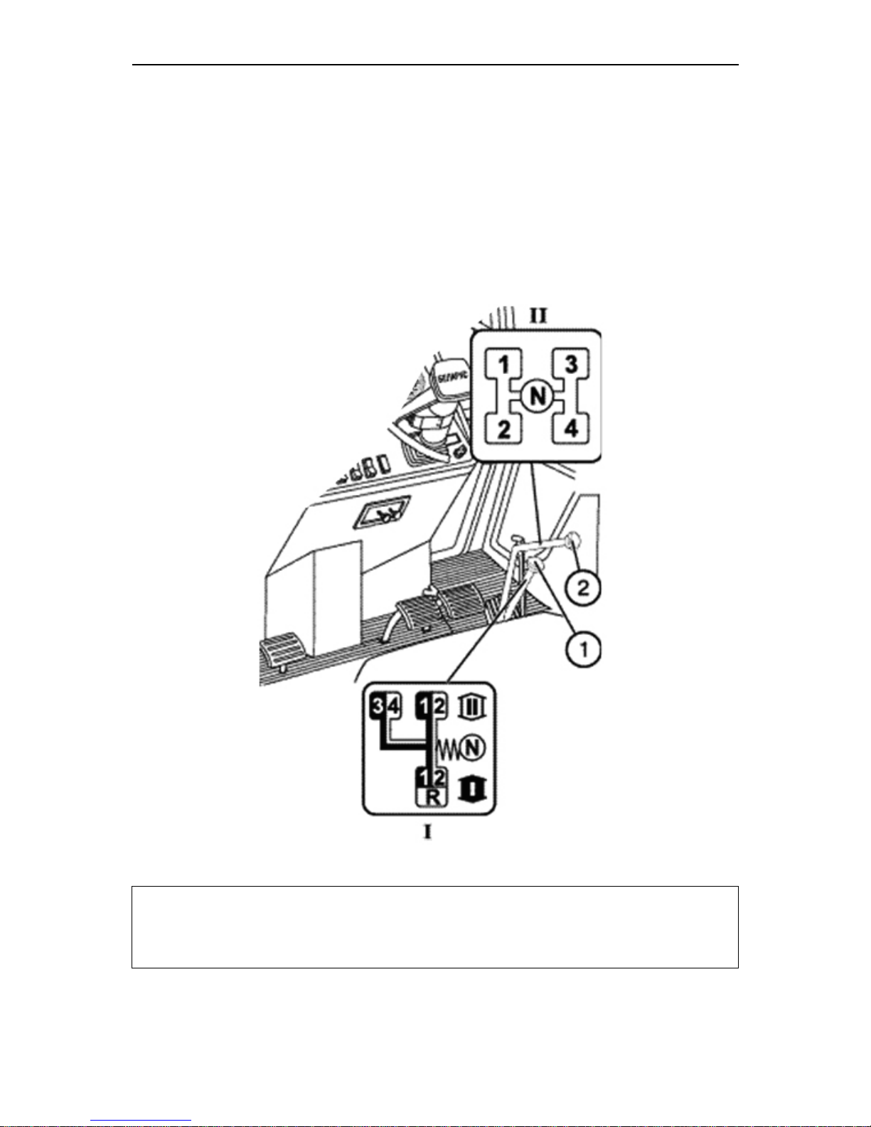
Gearbox control (16F+8R)
The gearbox is controlled by two levers:
a lever of ranges shifting (1) and a lever
of gears shifting (2).
Select the required ranges and gears in
accordance with the shifting patterns I
and II as shown on the figure below.
IMPORTANT! In order to shift the gear correctly smoothly, without jerks, move the
gear shifting lever (2) in accordance with the pattern (see the figure above) and keep it
pressed until the gear is switched.
Page 36
MTZ 1220.1/1220.3 Section D . Operation controls and instruments
D16
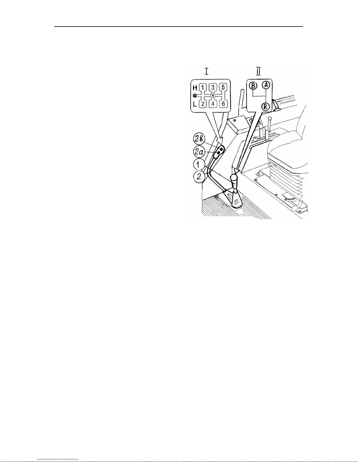
Gearbox control (24F+12R) (if installed)
Gears shifting lever (2)
The shifting pattern is shown in the figure on the right (pattern I).
“On” button (2) of gearbox reducer
low gear (L).
On” button (2) of gearbox reducer
high gear (H).
Ranges shifting lever (1)
The shifting pattern is shown in the figure on the right (pattern II).
– two low ranges of forward motion;
– two high ranges of forward motion;
R – two ranges of reverse motion;
–high pass of gearing;
L – low pass of gearing.
Page 37
MTZ 1220.1/1220.3 Section D . Operation controls and instruments
D17
Control of the rear axle differential
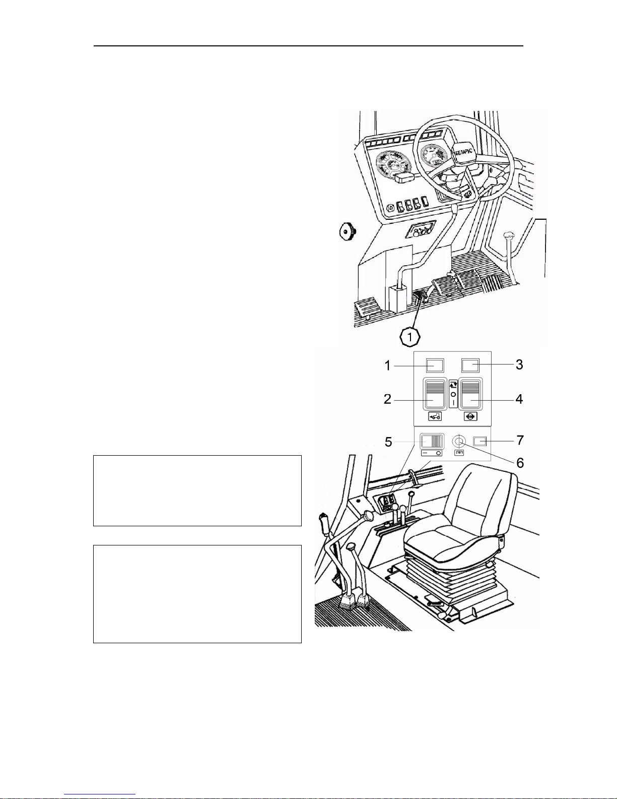
lock
The rear axle differential lock is controlled by the button (4), located on the
dashboard near FDA control button (2).
Three position button (4) has the following positions:
• “Automatic locking” — on pressing the
upper part of the button (fixed position);
• “Differential lock is switched off —
middle position (fixed);
• “Forced blocking” — on pressing the
lower part of the button (unfixed). When
the button is released it automatically
switches to the middle position (“Differential lock is switched off”).
On switching on the differential lock
alarm lamp (3) lights up, which goes off
when the differential lock switches on automatically and when the button (4) is put
in the middle position.
Important! Engage the forced differential lock only shortly to overcome
road obstacles and carry out the field
and transportation works.
Warning: Do not use the differential
lock at the speeds exceeding 10 km/h
and when turning the tractor. Otherwise the tractor control becomes difficult, power transmission is quickly
worn out, the safety is endangered.
Page 38
MTZ 1220.1/1220.3 Section D . Operation controls and instruments
D18
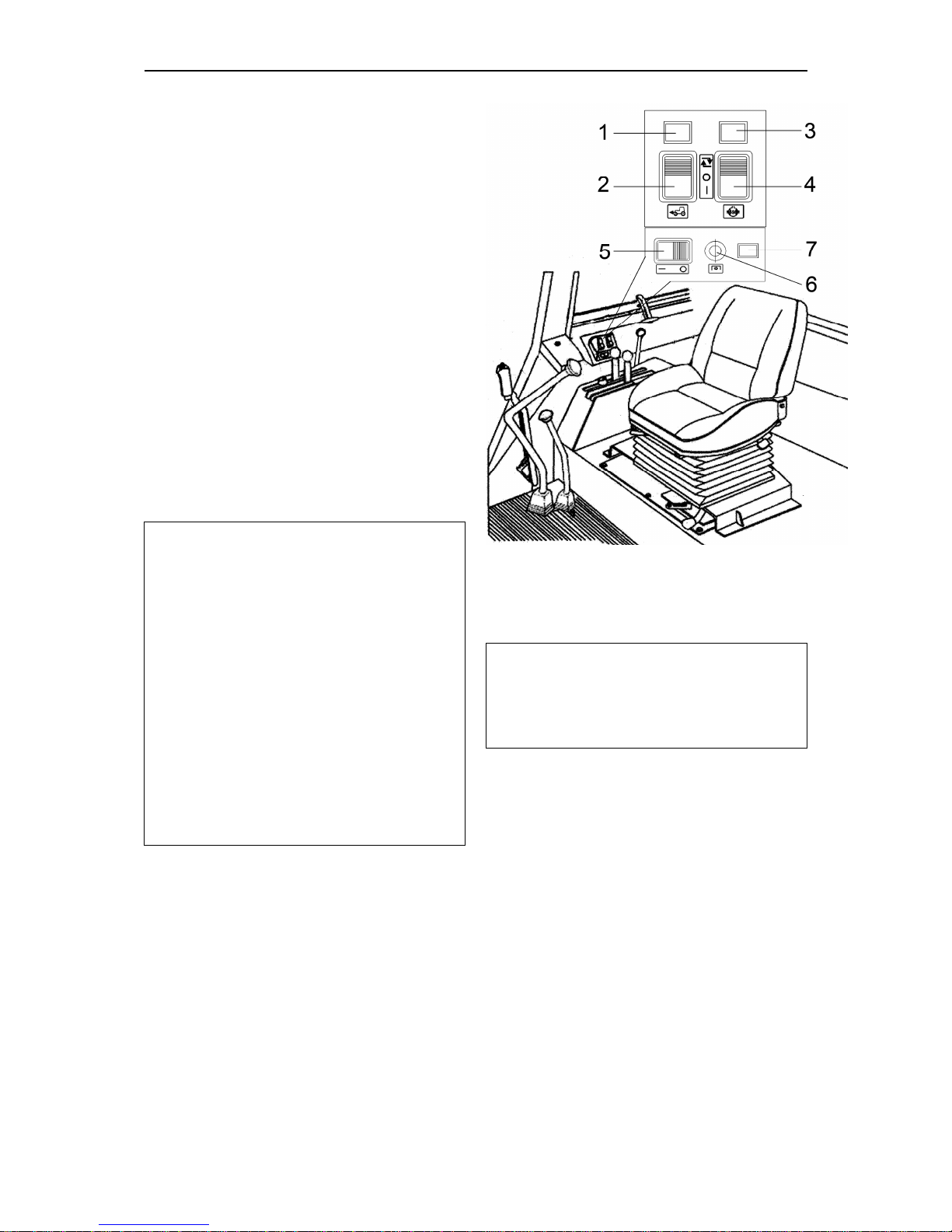
FDA drive control
FDA drive is controlled by the button (2),
located on the board above the right control unit. The button (2) has three fixed
positions:
• “FDA is automatically “on” — on
pressing the upper part of the button;
• “FDA is “off” — middle position of the
button;
• “Forced FDA engagement” — on
pressing the lower part of the button.
On engaging FDA drive the alarm lamp
(1) lights up. The lamp goes out on
putting the button (2) in the middle position and in the moment of switching off
the drive in the automatic mode.
Attention!
1. Operating on the roads with hard
surface switch off the FDA (middle position of the button (2) in order to prevent tyres and drive parts from increased wear.
2. Use the forced FDA engaging mode
shortly only to overcome obstacles.
3. It is categorically forbidden to operate in the mode of forced FDA engagement when the speed is over 15
km/h.
4. It is categorically forbidden to use
FDA in the mode of automatic engagement by the reverse motion.
Note: A braking relay is installed in the
electrical line of FDA drive control, it
ensures automatic switching on of FDA
when pressing synchronized pedals of
tractor brakes.
Page 39
MTZ 1220.1/1220.3 Section D . Operation controls and instruments
D19
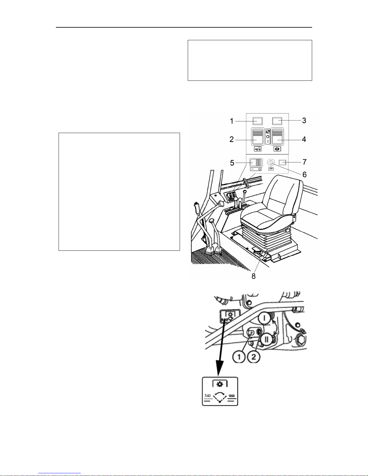
Rear PTO engagement
In order to engage PTO press key (5) to
the left up to the stop, then press key (6)
and release it, then indicator lamp (7)
(yellow) will light up indicating PTO shaft
engagement.
In order to disengage PTO shaft press
key (5) to the right, indicator lamp (7) will
go out, indicating PTO shaft disengagement.
ATTENTION
!
Disable PTO shaft drive if it is not
used.
Before starting diesel engine ensure,
that key (5) and button (6) of PTO
shaft switching on and off are in the
position “PTO off” (indicator lamp (7)
is off).
Disable drive while deenergizing control system (failure of generator, belt
breakage and etc.) in order to exclude
premature failure of PTO reducing
gear elements.
Independent and synchronous PTO
drives
The lever (8) has three positions:
• “Independent drive is engaged” — ex-
treme right position;
• “Synchronous drive is engaged — ex-
treme left position;
• “Disengaged” — middle position.
Engage the synchronous PTO drive only
at low gears on minimum engine idle
speed doing the following:
• Start the engine and set the minimum
idle speed;
• Press home the clutch pedal and en-
gage I or II gear;
• Release the clutch pedal slowly and
simultaneously turn the lever (8) in the
extreme left position.
Important! Use the PTO synchronous
drive only at low gears at tractor motion speed not higher than 8 km/h.
Otherwise tractor power train may get
seriously damaged.
Speed switch of independent PTO
drive
Independent drive lever (1) has two positions:
Page 40

MTZ 1220.1/1220.3 Section D . Operation controls and instruments
D20
I — 540 rpm — extreme, contraclockwise;
II — 1000 rpm — extreme clockwise.
To set a required PTO speed release the
bolt (2), turn the lever (1) and tighten the
bolt (2).
Page 41
MTZ 1220.1/1220.3 Section D . Operation controls and instruments
D21
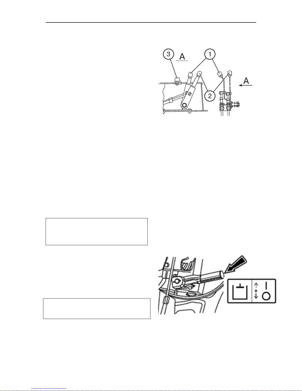
Hydraulic lift linkage control
with hydraulic lift
The hydraulic lift linkage is controlled using two control levers (1) and (2), located
on the right control board inside the cab.
The draft control lever (1) is the nearest
to the operator's seat and has the following positions:
• Extreme forward — maximum depth
of ploughing (“9”).
• Extreme rearward — minimum depth
of ploughing (“1”). Full range of the
lever's positions is denoted with number from “1” to “9”.
The position control lever (2) has following positions:
• Extreme rearward (“1”) — transport
position of rear lift device.
• Extreme forward (“9”) — minimum
height of the implement above the
ground.
The maximum lifting height of the implement using the lever (2) is eliminated by
adjustable stop (3).
Note: The mixed control is carried out
by means of the limitation of the tillage
depth using the lever (2) during draft
control operations.
Hydraulic system pump control
The control lever has two positions:
• “The pump is engaged” – upper position;
• “The pump is disengaged” – lower position.
Important! Disengage the pump at cold
start or maintenance. Engage the pump
at the engine minimum idle speed only.
Page 42
MTZ 1220.1/1220.3 Section D . Operation controls and instruments
D22
Gearbox oil pump control
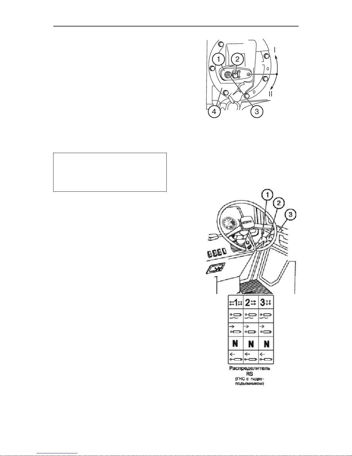
The gearbox oil pump control lever (1)
can have two fixed positions:
I — “Pump drive from engine” (normal
operating position) — the lever
(1) is turned counterclockwise
(when looking at GB from the left
tractor side) relative to the axis
(3) until the lower edge of the
lever slot stops and is fixed by the
bolt.
II — non-working position.
Important! Set the lever (1) in the position II when there is a necessity to
remove and to mount the assembled
GB pump drive (4) and then fix the
lever (1) in the position I again.
Hydraulic system distributor control
Each of the three remote levers (1, 2,
3), controls the remote cylinders and
has four positions:
• “Neutral” — low middle (fixed);
• “Lift” — low (non-fixed); after releas-
ing the lever returns to “neutral";
• “Positive lowering” — upper middle
(non-fixed) between the “float” and
“neutral”. After releasing the lever
returns to “Neutral";
• “Float” — upper (fixed)
Page 43
MTZ 1220.1/1220.3 Section D . Operation controls and instruments
D23
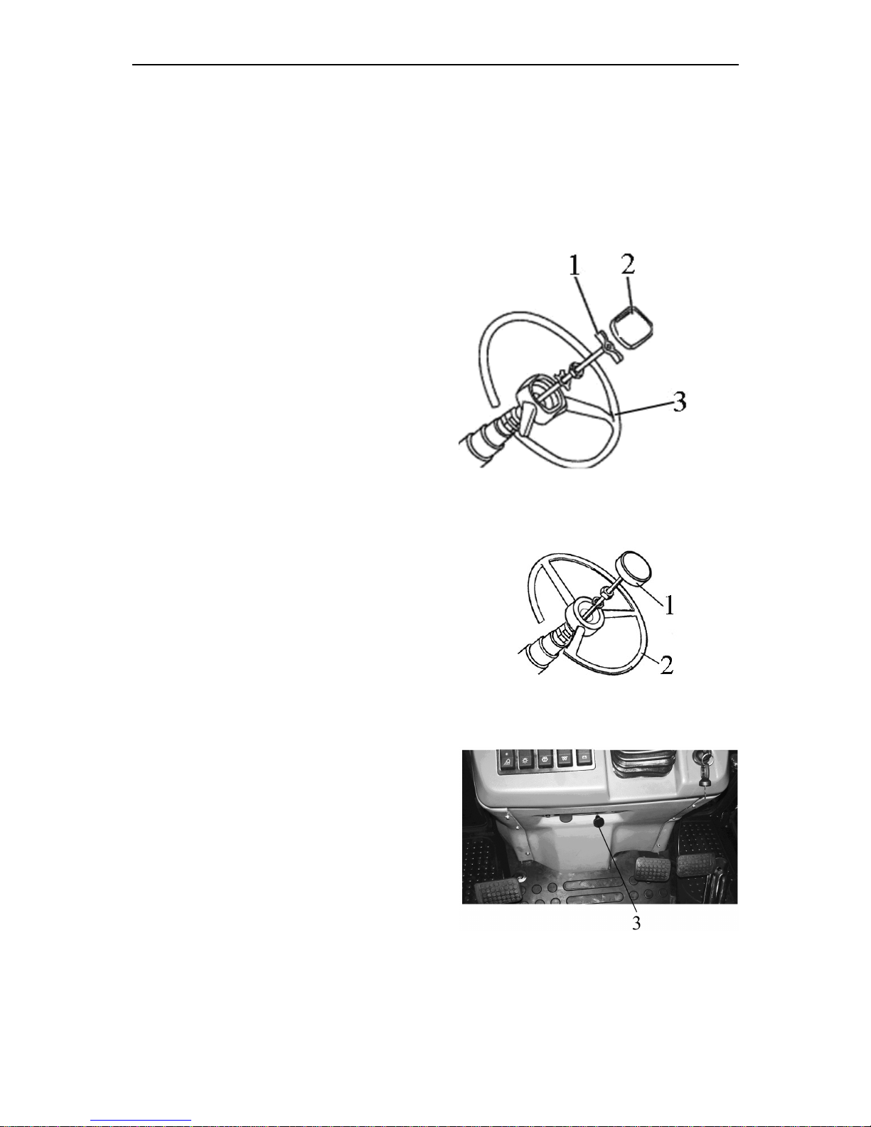
Changing of steering wheel position
To adjust the height of the two-arm
steering wheel, proceed as follows:
• Remove the cover (2);
• Unscrew the clamp (1) for 3…5
turns;
• Set the steering wheel 3 in the re-
quired position;
• Tighten the clamp (1) manually and
fix the cover (2) back.
• Steering wheel height adjustment
range is 100 mm.
To adjust the height of the tree-arm
steering wheel, proceed as follows:
• Unscrew the clamp (1) for 3…5
turns;
• Set the steering wheel 2 in the re-
quired position;
• Tighten the clamp (1) manually
• Steering wheel height adjustment
range is 100 mm.
The steering column can tilt to four different positions from 25° to 40° relative
to horizontal line in increments of 5°).
In order to tilt the steering column, pull
the handle (3) on.
Page 44
MTZ 1220.1/1220.3 Section D . Operation controls and instruments
D24
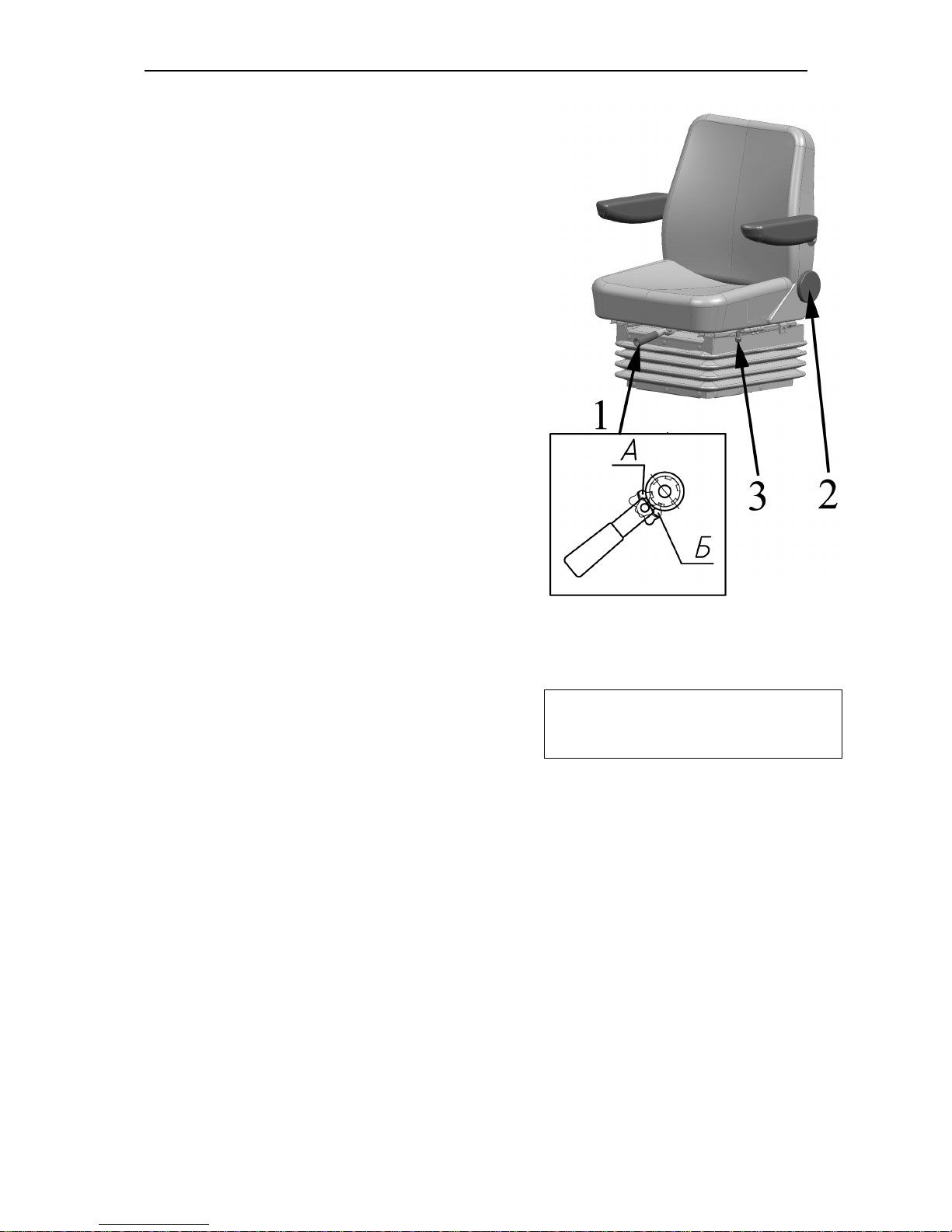
Seat “MTZ”
The seat has the following adjust-
ments:
Adjustment according to the op-
erator's weight is carried out by
means of lever 1. To adjust the seat for
a bigger weight it is required to shift the
pawl of the lever 1 into position “A” and
tighten the springs with a reciprocal
movement. To adjust the seat for a
smaller weight it is required to shift the
pawl into position “” and release the
springs with a reciprocal movement.
Adjustment of the backrest tilt
angle is adjusted by means of a
handwheel 2. To increase the backrest
tilt angle it is necessary to turn the
handwheel clockwise, to decrease it –
contraclockwise.
Longitudinal adjustment is
carried out by means of a lever 3. To
move the seat forward-backward it is
required to pull the lever 2 up, move
the seat and then release the handle.
The seat will automatically get fixed in
a required position.
Height adjustment. The seat has
three height positions: “lower”, “middle”
and “upper”. To move the seat from the
“lower” position to the “middle” position
or from the “middle” position to the “upper” one it is required to lift the seat up
smoothly till the arresting stop goes off
(a specific click is heard). To move the
seat from the “upper” position into the
“lower” one it is necessary to lift the
seat up against the stop with an abrupt
movement and let it down.
,
NOTE!
It is impossible to move the
seat from the “middle” position to the
“lower” one.
Page 45
MTZ 1220.1/1220.3 Section D . Operation controls and instruments
D25
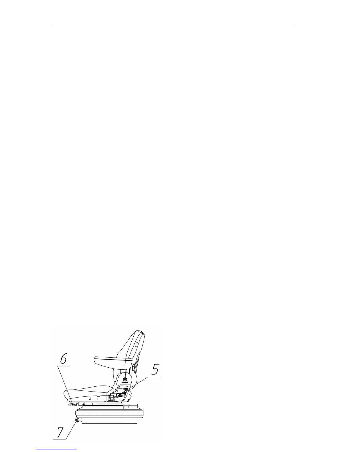
In case a Grammer seat is installed in
a tractor, adjustment according to the
operator's weight is carried out by
means of a lever 7. To adjust the seat
for a bigger weight it is necessary to
turn the handle clockwise. To adjust
the seat for a smaller weight, turn the
handle contraclockwise.
Longitudinal adjustment is carried out
by means of a lever 6, which shall be
pushed to the right up to the stop and
after which the seat may be moved forward or back. Height adjustment has
three height positions. To increase seat
height manually displace the seat successively upward (until you hear specific
click indicating fixation). To reduce the
seat height it is necessary to lift the seat
up against the stop with an abrupt
movement (from the upper position of
height adjustment) and let it down to the
lower position. Adjustment of the backrest tilt angle is carried out by lever 5.
To change the backrest tilt angle it is
necessary to raise the lever up to the
stop, chose the required backrest tilt
angle and releasing the lever, fix it in
the required position.
5 – adjustment of the backrest tilt angle;
6 – longitudinal adjustment;
7 – adjustment according to the opera-
tor's weight.
Page 46
MTZ 1220.1/1220.3 Section D . Operation controls and instruments
D26
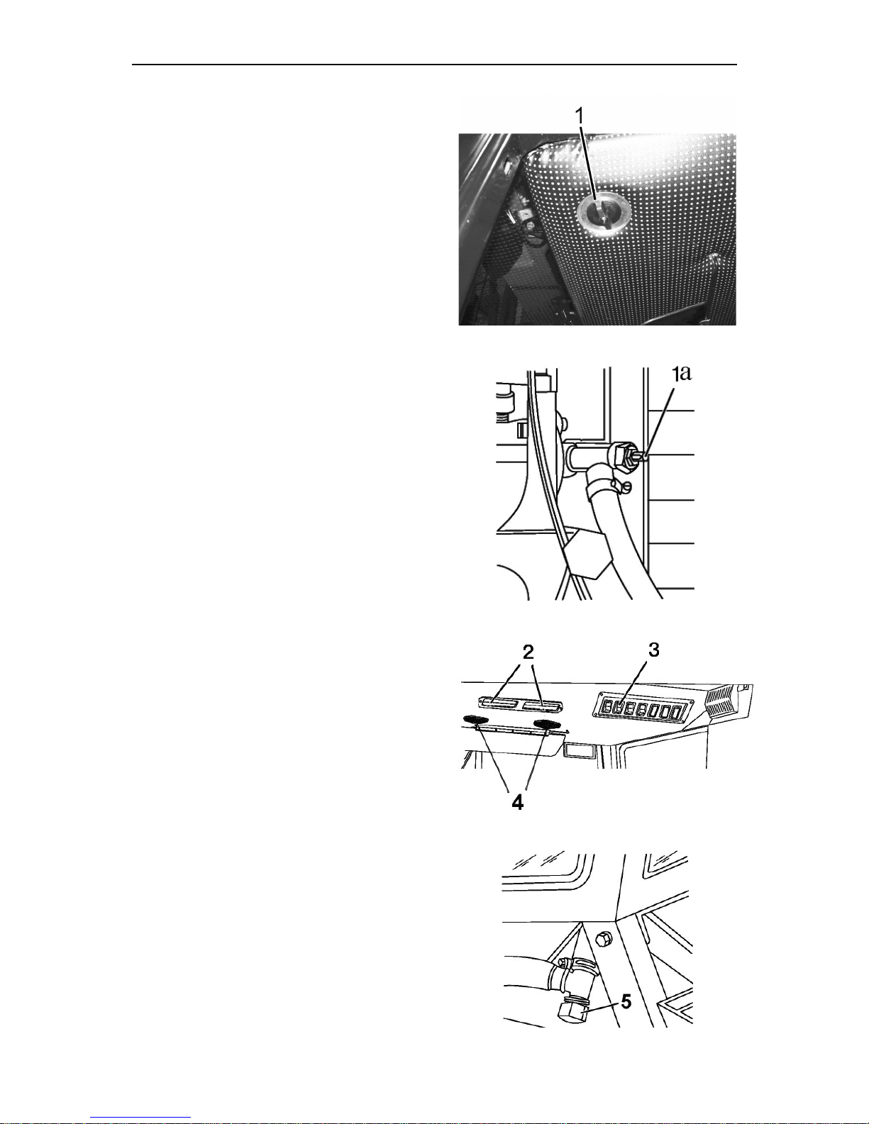
Cab heater fan control
To turn on the heater conditioner,
proceed as follows:
1. After refilling the cooling system
with antifreeze agent, start the engine
and let the engine work at medium
speed to have the antifreeze agent in
the cooling system warmed up to 50 to
60°, after that open the heater valve
by turning lever 1 of the heater counterclockwise up to the stop. If a heater
valve is installed outside a cab, turn a
lever 1. Then increase the engine
speed and let it work for 1 to 2 minutes, slightly open a plug 5 of a drain
valve cock on the right side to ensure
that cooling agent circulates through a
heat exchanger. The heat exchanger
must start warming up. The coolant
level in the diesel heat exchanger of
the engine cooling system will drop at
that
2. Add coolant to the diesel heat exchanger to the required level (50…60
mm below top edge of filler neck).
3. Engage heater fan with switch 3
and direct the air flow via air distributors 4.
4. with the recirculation shutters 2,
the quantity of fresh air delivered into
the cab can be adjusted.
5. To drain the coolant from the heating system there is drain plug 5 on the
left and right sides of a cab. After the
coolant is drained, it is necessary to
blow the system off with compressed air
after closing a valve cylinder block and
turning off plugs 5. Tighten the plugs
after blowing off.
ATTENTION: heater control valve
shall be closed for system operation in
ventilation mode during a warm season.
Page 47
MTZ 1220.1/1220.3 Section D . Operation controls and instruments
D27
Cab air conditioning and heating
system
If it is installed instead of a heater fan
Climate system control in air conditioning mode
The climate system control panel is in
the central part if cab upper panel.
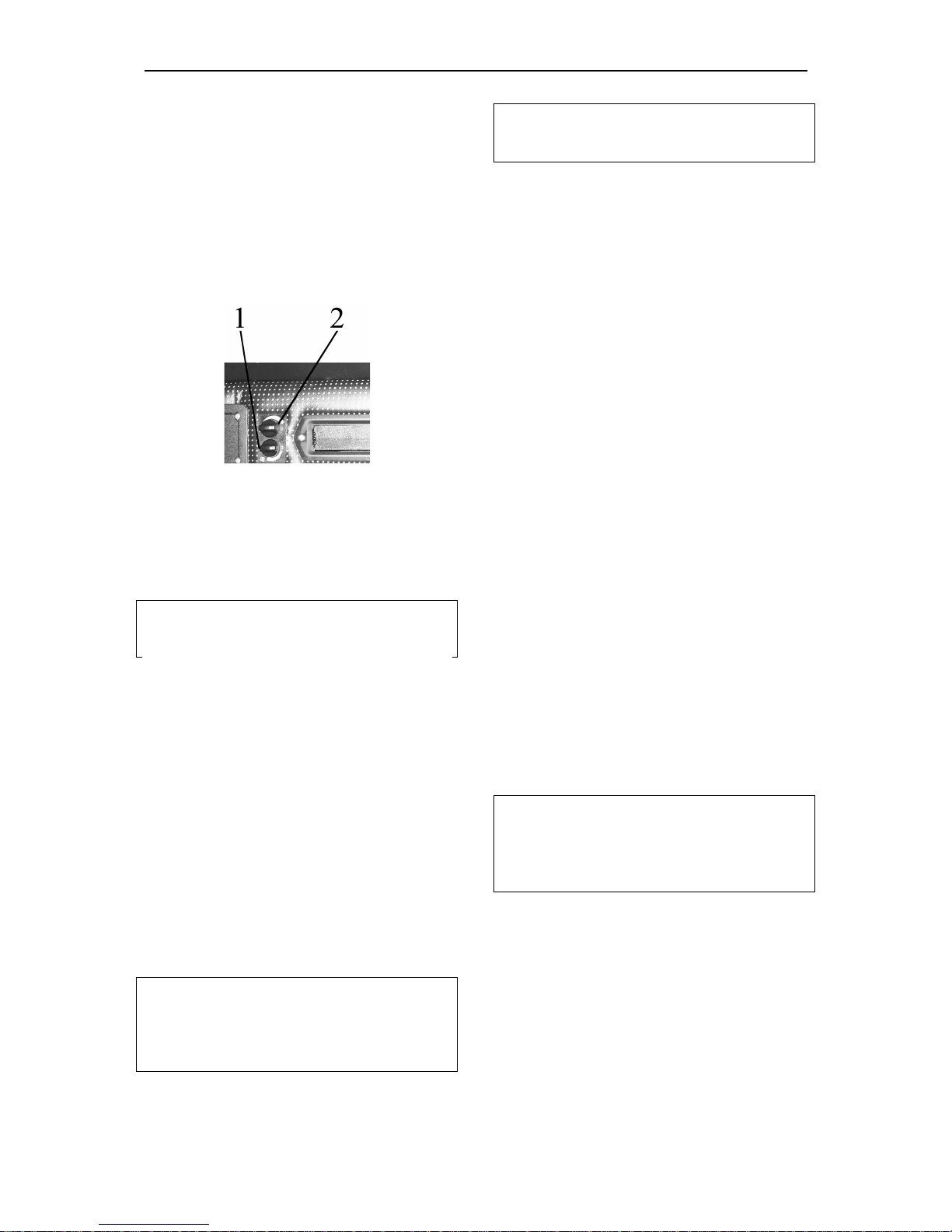
Control console has the switches (1)
and (2)
By means of air flow switch (1) you
can change air consumption by means
of fan operating speed change. By
means of air flow switch (2) you can
change temperature of the air coming
from cool and dehydrated air deflector in
air conditioning mode.
ATTENTION
:
air conditioner can be
turned on and operate only when the
engin
e is running
To turn on the conditioner, proceed
as follows:
- turn the switch (2) (Figure 2.7)
clockwise by 180°C to the beginning of
the blue scale;
- - then turn the switch (1) to one of
the three marked positions (the fan impeller has three speeds). In 3-5 minutes, use the switch (2) to adjust the
desired temperature in the cab;
- with the shutters located on the
upper panel, near to the operator's
head, the mix of external and recirculating air can be adjusted;
To turn off the air conditioner turn
both switches (1) and (2) counterclockwise to “0”.
ATTENTION
:
when working in the
cooling mode, the heater valve must
be closed to prevent simultaneous operation of the air heating and cooling
systems
.
Climate system control in heating
mode
ATTENTION:
REFILL THE ENGINE
COOLING SYSTEM ONLY WITH AN
ANTIFREEZE AGENT.
For efficient operation of the
heating system, observe the following
recommendations:
1. After refilling the cooling system
with antifreeze agent, start the engine
and, without opening the valve, let the
engine work at medium speed to have
the antifreeze agent in the cooling system warmed up to 70 to 80°, after
that open the valve, increase the engine speed and let it work for 1 to 2
minutes to have the heat exchanger
filled with the agent. Make sure that the
antifreeze agent is circulating through
the heater. The heat exchanger must
warm up. The coolant level in the heat
exchanger of the engine cooling system will drop at that;
2. Add coolant to the diesel engine
heat exchanger to the required level (to
the MAX. mar on the expansion tank);
3. To have the cab quickly warmed
up, turn on the heater fan and open the
recirculation shutters;
4. To discharge the coolant from the
engine heater and cooling system, install the tractor on an even surface.
Remove the extension tank plug of the
engine cooling system, open the valve
on the cylinder block of the engine and
remove the heater hose from the heater valve.
ATTENTION:
when working in the
heating mode, the switch 2 must be
fully off to prevent simultaneous operation of the air heating and cooling sys-
tems
.
Page 48
MTZ 1220.1/1220.3 Section D . Operation controls and instruments
D28
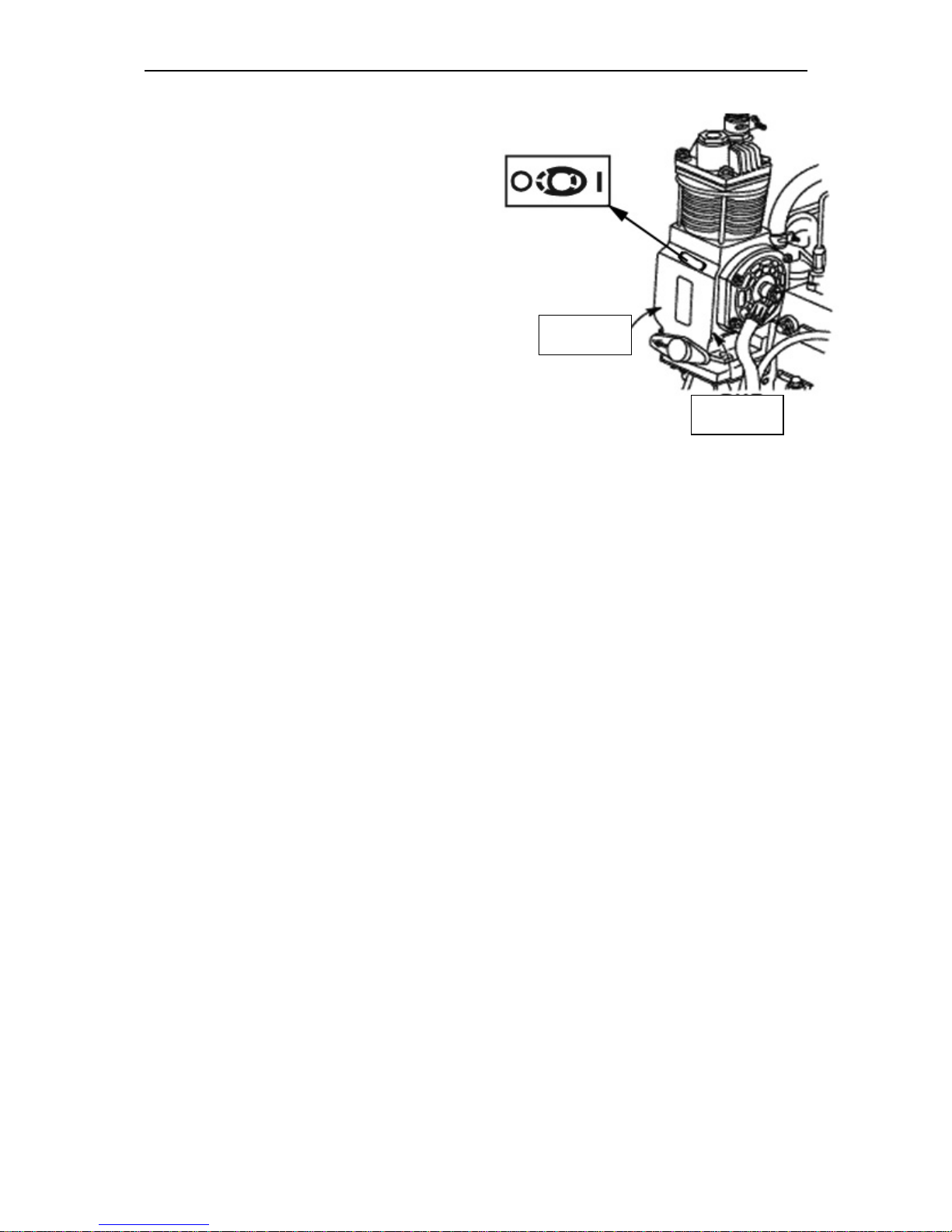
Pneumatic system compressor control
The handle of compressor control has
two positions:
• “Compressor ON” – when turning
the handle so that the arrow on
the arm is directed backwards to
tractor motion;
• “Compressor OFF” – when turning
the handle so that the arrow is directed forward to tractor motion.
OFF
ON
Page 49
MTZ 1220.1/1220.3 Section D. Construction and Operation
D1
CONSTRUCTION AND OPERATION OF TRACTOR COMPONENTS
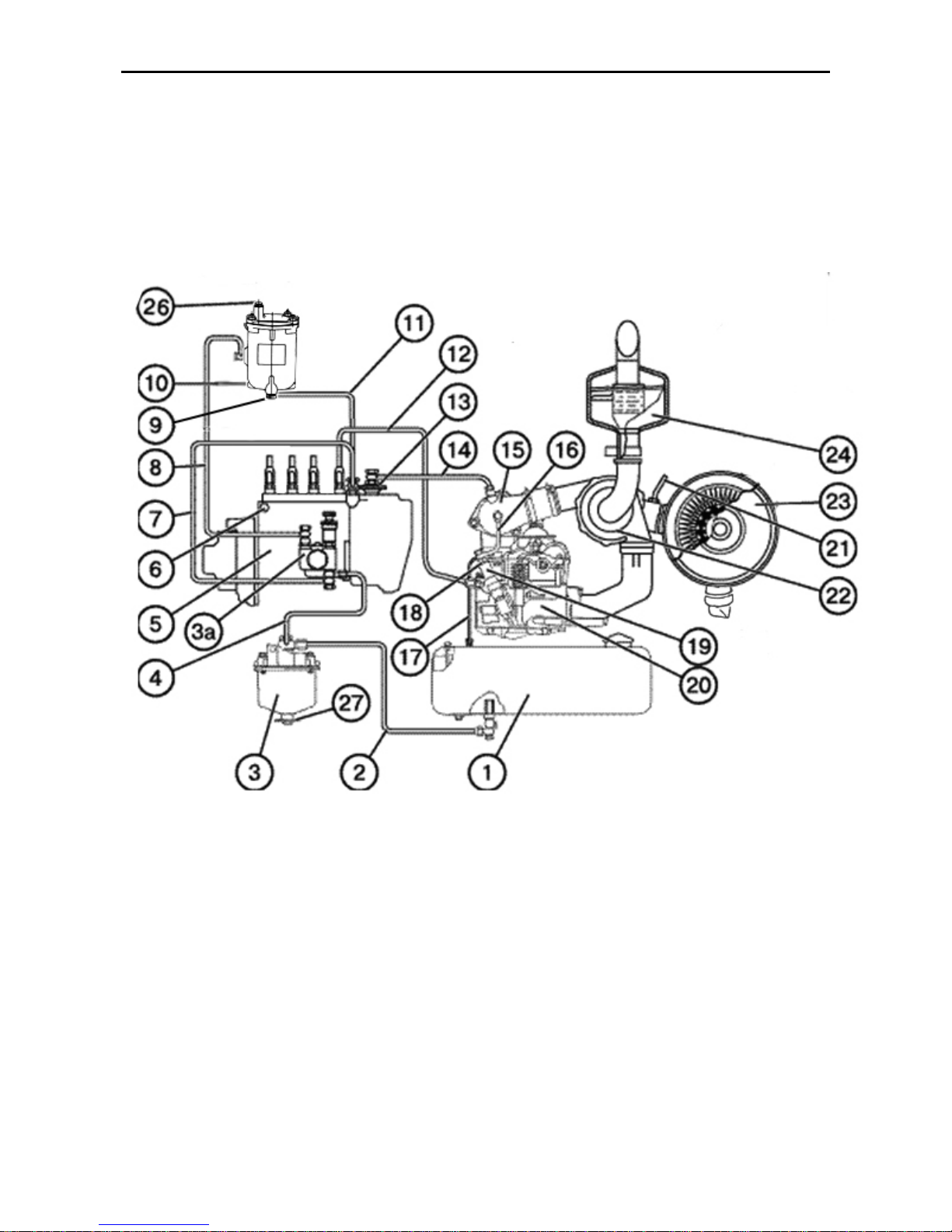
The Engine Feed Circuit consists of an air-cleaner, air-delivery conduit, induction/ ex-
haust manifolds, turbocharger, exhaust muffler, fuel tanks, coarse and fine fuel filters, fuel
pump, injectors as well as fuel-injection (high-pressure) and delivery low-pressure) pipelines.
Fig D-1. Feed system diagram
1 – fuel tank; 2 – connecting pipe from the fuel tank; 3 – coarse fuel filter; 4 – connecting pipe from the
coarse fuel filter; 5 – fuel pump; 6 – plug to bleed air from the fuel pump head; 7 – fuel offtake pipe from the
lower-pressure chamber to the fuel-lift pump; 8 – pipe to deliver fuel from the fuel-lift pump to the fine fuel
filter; 9 – sludge draining plug; 10 – fine fuel filter; 11 - fuel offtake pipe from the fine filter to the lowerpressure chamber of the pump; 12 – fuel injection pipe; 13 - pneumatic adjuster; 14 –pipe of air delivery from
air-delivery conduit downstream the turbocharger to the pneumatic adjuster; 15 – induction manifold; 16 –
fuel overflow pipe; 17 – fuel drain pipeline; 18 – fuel overflow pipe; 19 – injector; 20 – cylinder head; 21 – aircleaner clogging indicator pipeline; 22 – turbocharger; 23 – air-cleaner; 24 – exhaust muffler26 – air-bleeding
plug; 27 – plug to drain sludge.
Page 50
MTZ 1220.1/1220.3 Section D. Construction and Operation
D2
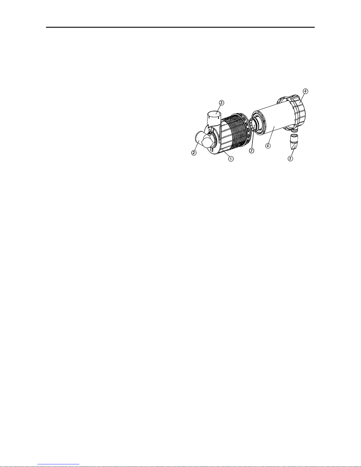
Air purifier (fig. Д-2 ) of Donaldson com-
pany of dry type using one paper filtering
element. It has three stages of cleaning.
The first stage - inertia air cleaning (inbuilt monocyclone). It is carried out inside
the air purifier at the cost of centrifugal
forces, emerging by air spiral rotation with
relation to the axis of the case (1) of the
air purifier. Dust is discharged through a
rubber cap (5), mounted on the cover (4)
of the air purifier, as the engine is stopped
and started, at the cost of excess pressure, emerging inside the air purifier. The
second and third stage is dry cleaning
with the main (6) and control (7) paper
filtering elements. Air is fed through the
air intake (3). The air is delivered to the
turbocharger through the air pipeline by
means of a delivery pipe 2.
The Coarse Fuel Filter with a screen filter
element cleans the fuel from mechanical
impurities and water. The sludge is
drained from the filter through a draining
plug located in the bottom part of the bowl
housing.
Fig. E-2. Air purifier: 1-housing; 2-delivery pipe; 3air intake; 4-cover; 5-rubber cap; 6-main paper
filterung element (MFE); 7-control paper filtering
element (CFE). .
Fine fuel filter (fig. Д-1) has a replaceable
paper filtering element. The filtering ele-
ment is mounted in the filter housing.
The fine fuel filter is intended for multiple
usages subject to regular replacement of
filter elements and rubber gaskets and
observance of the operating instructions.
To bleed air from the engine fuel feed circuit, the filter bowl is provided with a plug
(26), refer to Figure below.
The fuel is injected into the cylinders by
the closed-type injectors (19) with fivebore nozzles.
The diesel fuel injection (highpressure) pump is of in-line four-plunger
type providing the metering of fuel by
changing the fuel-feed end point.The
pump is provided with a pneumatic antismoking adjuster and driven off the crankshaft through valve control gearing.
The fuel pump forms an integral unit with
a fully-variable all-speed governor and a
piston-type fuel-booster pump.
Mechanical centrifugal all-speed direct action regulator with automatic increasing of
fuel feed during diesel engine start.
The Fuel-Booster Pump (3a) is mounted
on the fuel injection pump body and driven
by the camshaft eccentric.
For bleeding the air from the feed system,
a hand- operated piston-type lift pump is
provided, and the plugs serve for bleeding
the air from the fuel-pump head The fuel
supply is controlled by means of the pedal
and lever.
The fuel pump parts are lubricated from
the engine lubrication system
Page 51
MTZ 1220.1/1220.3 Section D. Construction and Operation
D3
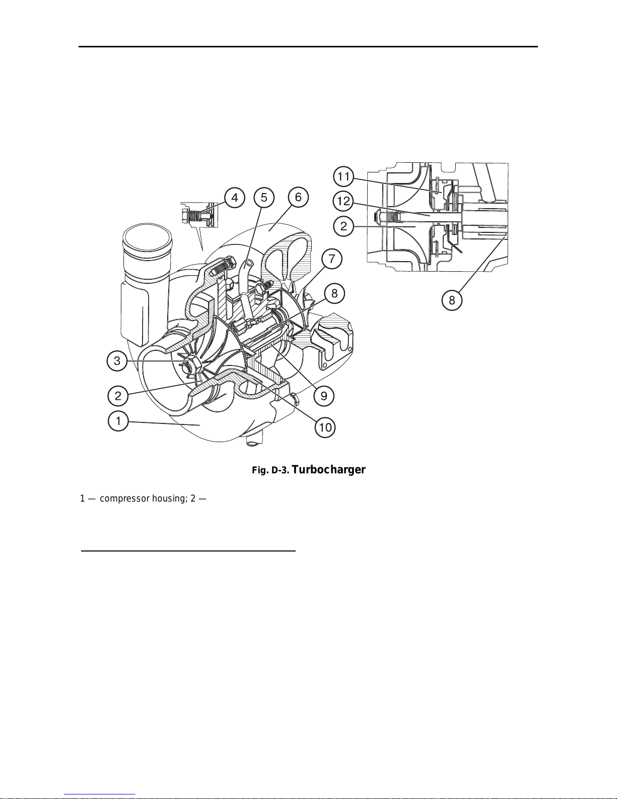
Turbocharger
The turbocharger serves for charging air
into the engine cylinders using the energy
of exhaust gases. It consists of a centrifugal one-stage compressor (2) and a radial
centripetal turbine (7).
The turbine wheel (7) is cast of a refractory nickel allow and welded to the rotor
shaft (12). The compressor wheel (2) is an
aluminium alloy casting and is attached on
the rotor shaft by means of a special nut
(3).
Fig. D-3.
Turbocharger
1 — compressor housing; 2 — compressor impeller; 3 — special nut;
4 — retaining holdfast; 5 — oil pipeline with mounting flange; 6 — turbine housing; 7 — turbine wheel ; 8 —
bearing; 9 — intermediate body; 10 — diffuser; 11 — disk; 12 — shaft
The principle of operation of the turbocharger is as follows. The exhaust gases
from the cylinders enter the gas-turbine
chamber from the exhaust manifold. Expanding, the gases rotate the turbine
wheel together with its shaft, on the other
end of which the compressor impeller is
fitted.
From the turbine gases are discharged
into the atmosphere through the exhaust
pipe.
The excess air pressure downstream the
compressor under engine design condition
should be 0.05…0.08 MPa (0.5…0.8
kgf/cm2).
Page 52
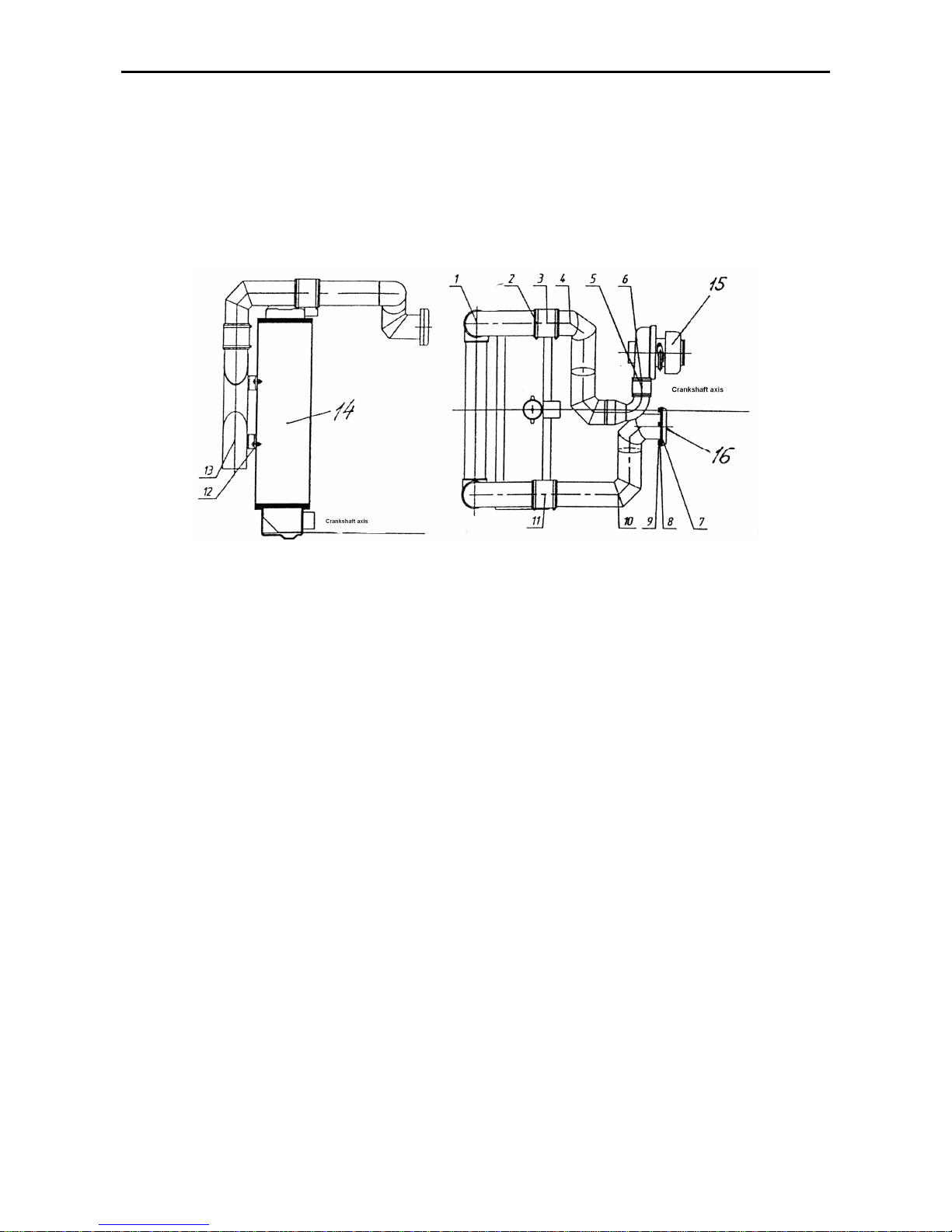
MTZ 1220.1/1220.3 Section D. Construction and Operation
D4
Installation of charged air cooler (CAC)
The charged-air cooler 5 is mounted in
front of the water radiator (14) and is
linked to the turbocharger (15) and engine
intake manifold (16) through the system of
air pipelines (1,4,10) and pipes (3,5,11).
The CAC is an air heat exchanger, consisting of a core as finned aluminum
pipes, tanks and connection tubes. Air is
delivered to the CAC from the turbocharger, cooled inside it to improve powerefficient and ecological parameters of the
engine and further comes to the engine air
intake.
Fig. D-4. CAC installation:
1,4,10 – air pipeline; 2,6 – clamp; 3,5,11 – pipe; 7 – seal; 8 – washer; 9 – bolt 816; 12 - nut; 13 – cooler
(CAC); 14 – water radiator; 15 – turbocharger; 16 – diesel engine intake manifold.
The engine lubricating system is combined (Fig.D5): some parts are forcelubricated; others are splashed lubricated.
The bearings of crankshaft and cam shaft,
bushing of intermediate gear, crankshaft
rod bearing of compressor, valves drive
mechanism (rocking arms) and turbocharger shaft bearing are lubricated by the
oil pump under pressure. Sleeves, pistons, piston pins, barbells, pusher, cam
shaft claws and fuel pump drive are lubricated by spraying.
The full-flow oil filter with complete filter
element and liquid-oil heat exchanger is
installed to diesel engines Д-245.2S2. The
plan of lubricating system is on figure Д-5.
The oil pump takes oil from the crankcase
1 through the oil Figk-up 8 and delivers it
through passageways in the cylinder block
to liquid-oil heat exchanger, and then to a
full-flow oil filter where oil is purified from
foreign substances, wear products and oil
decomposition products through heating
and oxidation.
The purified oil comes from the oil filter to
the oil pipeline of the diesel engine.
The overflow (reducing) valves are installed:
- in the housing of the liquid-oil heat exchanger - 11 (actuation pressure –
0,15
05.0+
MPa);
- in the oil filter - 13 (actuation pressure –
0,15
02.0
±
MPa);
During diesel engine start with cold oil,
when the oil flow resistance in the liquid-oil
heat exchanger exceed 0,15…0,2 MPa,
overflow valve opens and oil is delivered to
the oil filter, bypassing the liquid-oil heat
exchanger. When the resistance in the oil
filter is 0,13…0,17 MPa, the oil filter overflow
valve opens and oil comes to the oil pipeline,
bypassing the oil filter. The overflow valves
are not regulated.
The safety regulated valve 14 is installed to the filter housing. It is used to
maintain the oil pressure in the main oil
pipeline within the range 0,25...0,35 MPa.
The surplus oil is delivered through the
valve to the diesel engine crankcase.
Page 53
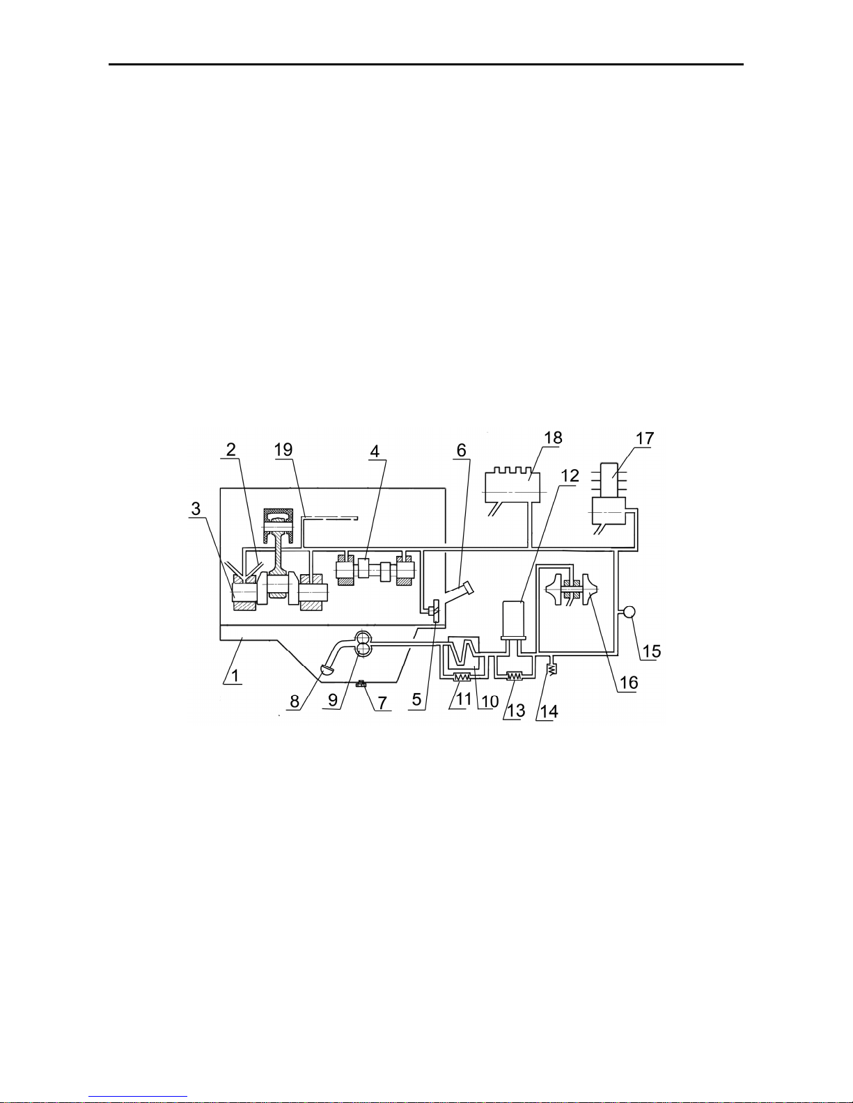
MTZ 1220.1/1220.3 Section D. Construction and Operation
D5
In case of excessive clogging of filter
paper, when oil filter resistance exceed
0,13...0,17 MPa, the oil filter overflow valve
also opens and oil comes to the oil pipeline,
bypassing the oil filter.
The plug of the reducing valve
must not be turned off at the operating
diesel engine.
Oil is delivered from the main pipeline
of the diesel engine through passageways
in the cylinder block to all crankshaft main
bearings and camshaft necks. Then oil
comes from main bearings through passageways in the crankshaft to all rod bearings. Oil is delivered from the first main
bearing trough the special passageways to
the intermediate gear bushings and fuel
pump drive gear and the fuel pump.
The parts of the valve mechanism
are lubricated with oil, which comes from
the rear bearing of the camshaft through
the passageways in the block, cylinder
head, drilled hole in the IV. rocking arm
shank to the body cavity of the rocking
arm axle and through the opening to the
rocking arm bushing from which it comes
to the adjusting screw and barbell.
Oil is delivered to the compressor
from the main pipeline through the drilled
holes in the cylinder block and special oil
pipeline. From the compressor oil is
drained to the diesel engine crankcase.
Oil comes to the bearing unit of the
turbocharger through the pipe at the oil
filter housing outlet. From the bearing unit
of the turbocharger oil is delivered through
the pipe to the oil crankcase.
Fig. D-5
The lubrication system diagram
:
1 – crankcase; 2 – piston cooling jet; 3 – crankshaft; 4 – distribution camshaft; 5 – intermediate gear; 6 – oil
throat; 7 – oil crankcase plug; 8 – oil Figk-up; 9 – oil pump; 10 – oil-to-fluid heat exchanger; 11 – transfer
valve; 12 – oil filter; 13 – transfer valve; 14 – relief valve 15 – pressure sensor; 16 – turbocharger; 17 – compressor; 18 – fuel injection pump; 19 – oil passageway of the rocking arm axle
.
Page 54
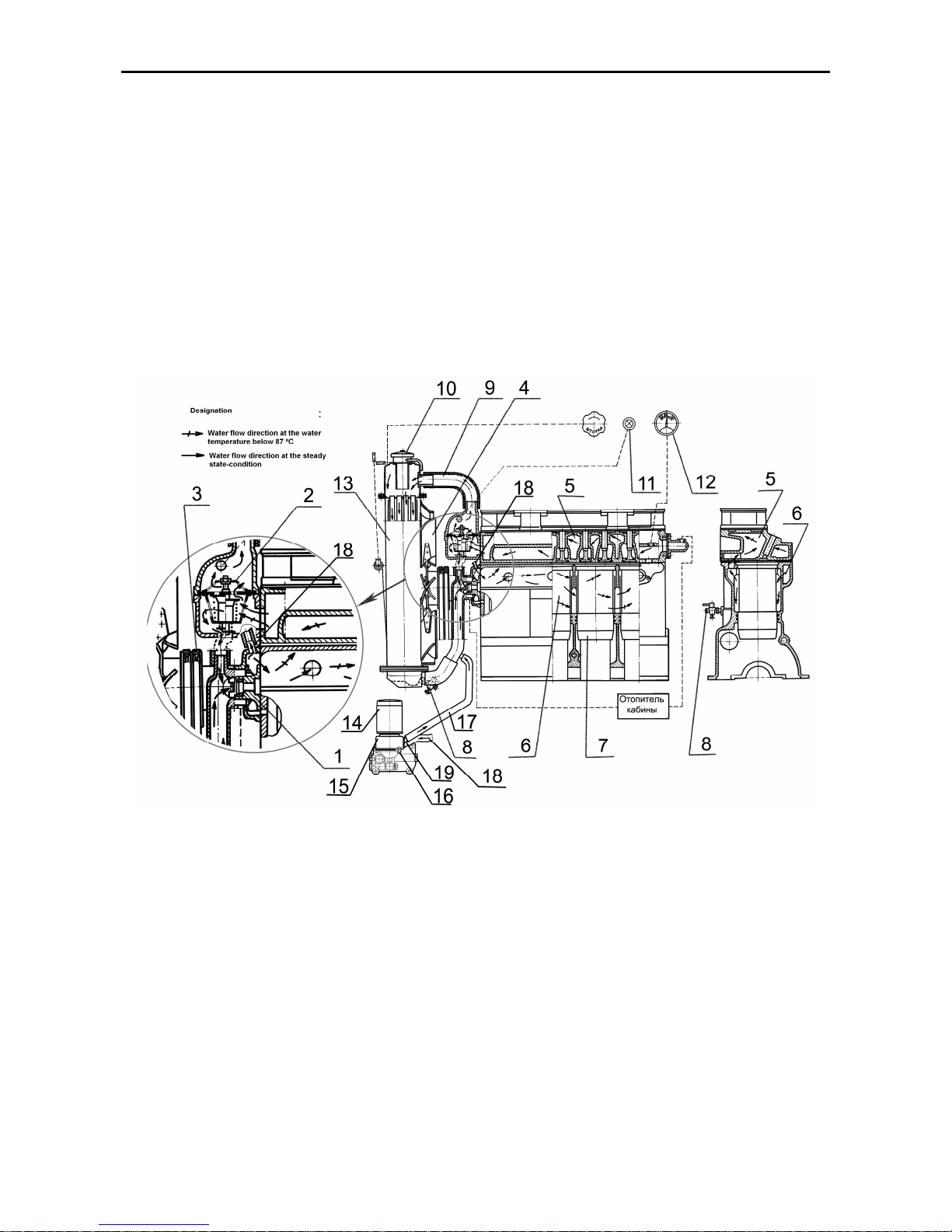
MTZ 1220.1/1220.3 Section D. Construction and Operation
D6
The Engine Cooling System (Fig. Д-6) is
of a closed liquid-type with forced circulation of the fluid from the centrifugal pump.
The water pump is rotated with V-belt
fromt the crankshaft pulley. The lubricant
Lithol-24 is put to the bearing hole of the
pump during the montage. The lubrication
of the bearings during the operation is not
needed.
The coolant temperature is monitored by
means of the remote temperature indicator, which is installed to the cylinder head.
Further, the sensor of the emergency coo-
lant temperature light is installed in the
thermostat cover.
The operation of the diesel engine is
forbidden when the emergency coolant
temperature light in the cooling system
flashes. The coolant temperature in the
cooling system is to be maintained within
the range 85º С …95º С. The thermostat
with opening temperature of the main
valve 87±2 °С serves for fast heating of
the diesel engine after start and automatic
temperature regulation at various loads
and ambient temperatures.
Fig. D-6
Engine cooling system diagram
:
1- water pump; 2 thermostat; 3 – water-pump drive belt ; 4 – fan; 5 – cooling jacket of cylinder head; 6 –
cooling jacket of cylinder block; 7 – cylinder block sleeve; 8 –coolant drain tap; 9 – branch pipe; 10 – filler
neck plug;
11 – a coolant temperature warning lamp; 12 - engine coolant temperature indicator; 13 – cooler;
14 – oil filter; 15 – oil-to-fluid heat exchanger ;16 – coolant drain plug; 17 – coolant drain branch pipe; 18 –
coolant inlet branch pipe.
Page 55

MTZ 1220.1/1220.3 Section D. Construction and Operation
D7
Electric Equipment and Starting System
The electric equipment aggregates installed on the engine, include the alternator with the capacity of 1150 W and voltage of 14 V.
, which is non-contact five-phase like
poles electrical machine with one-way
electromagnetic excitation, integral rectifier block and integral voltage regulator.
The generator is driven by V-belt from the
crankshaft pulley.
The diesel engine is started by electrical
starter (voltage 24 V, power 5,5 kW).
Remote starter actuation, with electromagnetic relay and starter switch.
For better diesel engine start at the lower
temperatures remote glow plugs are used
in the cylinder head of the diesel engine.
These plugs heat draw-in air in the cylinders.
Pneumatic system compressor
The diesel engine is equipped with the
piston one-cylinder single-stage compressor, which is installed in the flange of
the distributor valve cover and is driven
by drive gear of the fuel pump. This compressor is a part of the pneumatic system
of the tractor.
Page 56
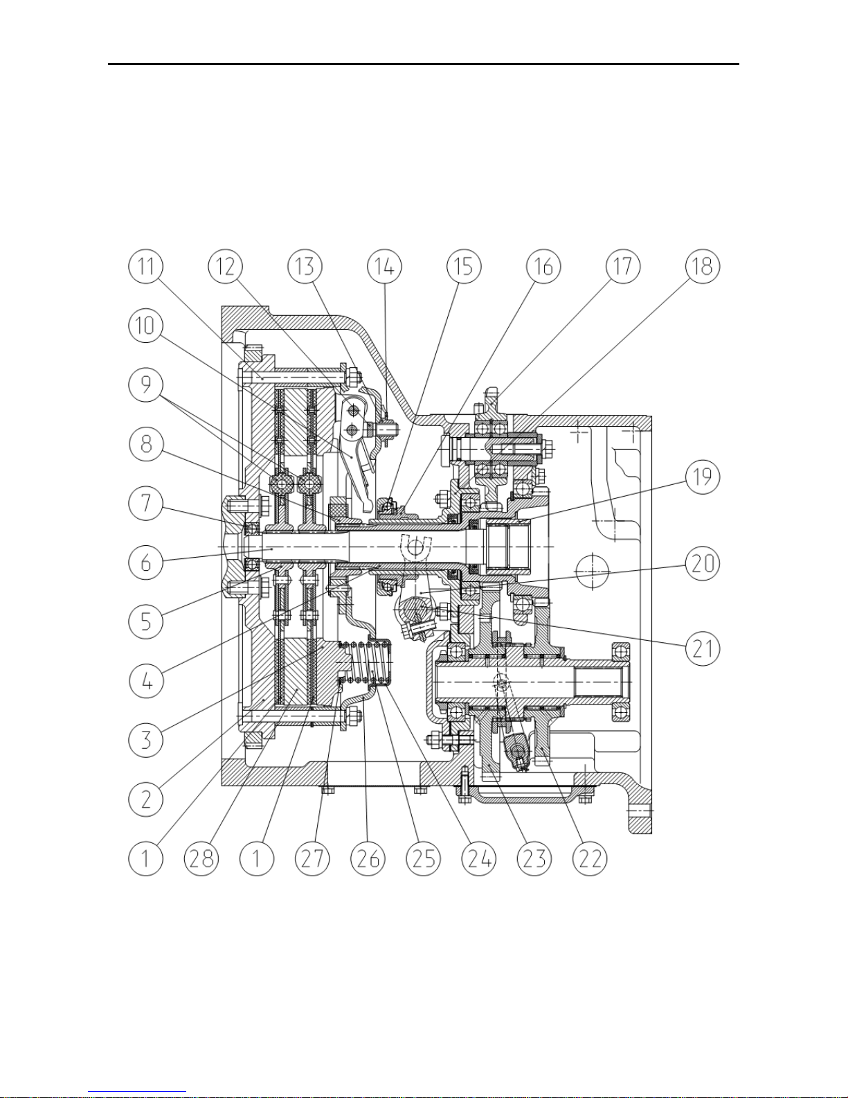
MTZ 1220.1/1220.3 Section D. Construction and Operation
D8
Power transmission
The power transmission comprises clutch,
gearbox, FDA drive, FDA and rear axle. It
serves for torque transfer from diesel engine camshaft to the front and rear
wheels.
Clutch
The clutch (Fig. Д-10) of the tractor consist
of the clutch coupling (elements 1, 3, 5, 710, 12-14, 24-28 Fig. Д-10) and clutch
housing (elements 6, 15-23 Fig. Д-10).
Fig. D-10. Clutch:
1 – driven disk; 2 - flywheel; 3 – pressure disk; 4 – shaft of PTO shaft drive and HS of lift linkage; 5 - hub; 6 –
power shaft; 7 - bearing; 8 - hub; 9 - torque vibration damper; 10 – release lever; 11 - pin;
12 - fork; 13 – adjusting nut; 14 – lock plate; 15 – throw-out bearing; 16 - shifter;
17 – drive gear of HS lift linkage; 18 – shifter bracket; 19 – coupling bushing; 20 - fork;
21 – control shifter; 22, 23 –driven gear of PTO shaft drive; 24 - cage; 25 - spring; 26 – back plate; 27 – insulation
gasket, 28 – center plate.
Page 57
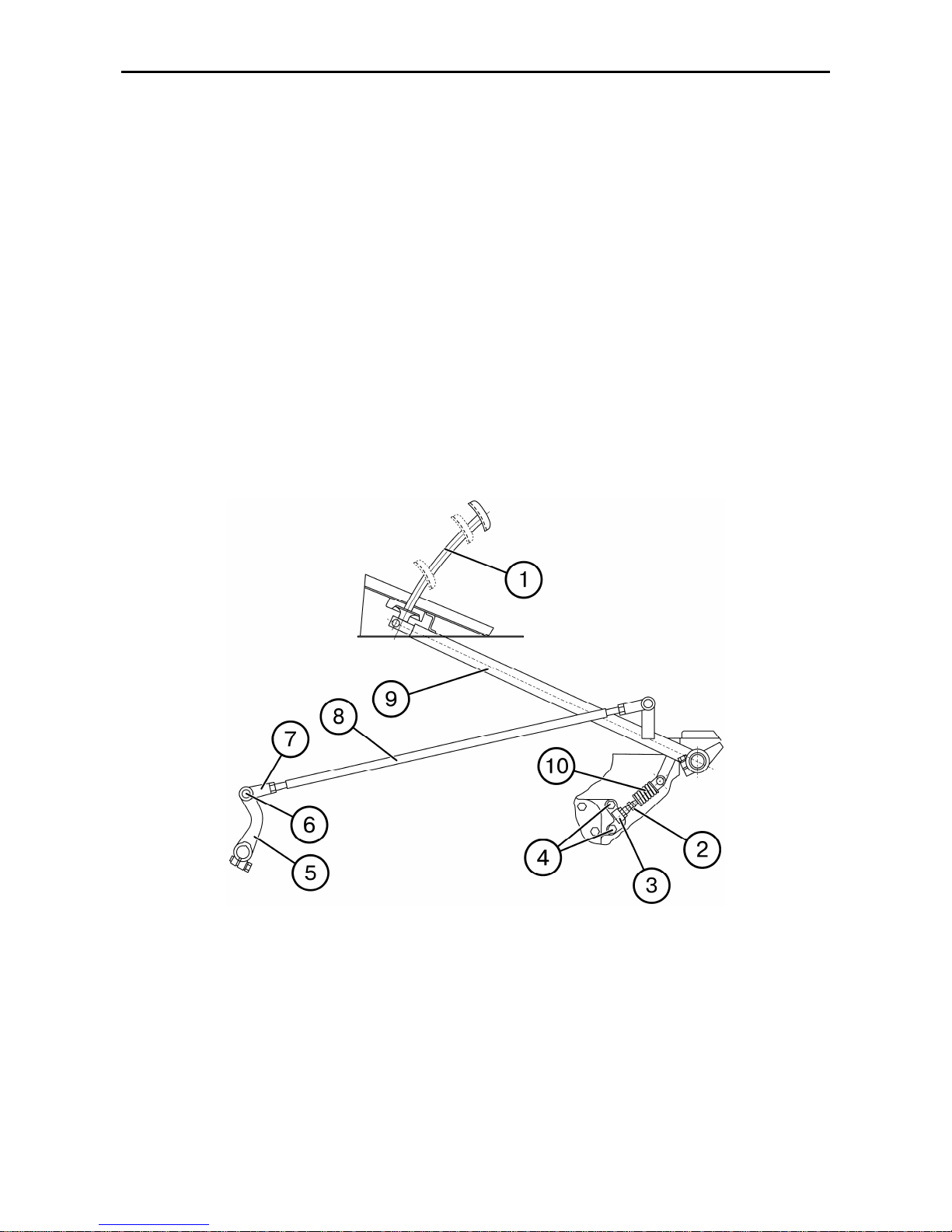
MTZ 1220.1/1220.3 Section D. Construction and Operation
D9
A dry-friction double-disk springloaded clutch coupling is mounted on the
engine flywheel 2. The clutch driving part
is a flywheel (2), a pressure plate (3) and
a center plate (28), which are fixed to the
flywheel pins (11) with tangential plates.
The clutch driven part consists of two driven plates (1) with torque vibration dampers (9), which are installed on the power
shaft (6). Nine springs (25) provide for a
required compression force of friction surfaces of driving and driven clutch parts for
torque transfer from the engine to the
transmission.
The release levers (10) rest on the
forks (12) fixed on the back plate by means
of adjusting nuts (13), locked by the lock
plates (14).
Clutch control (MTZ-1221.2/1221.3)
The clutch is disengaged by stepping on
the clutch pedal (1) (Fig.D-11) which acts
through the linkage (1), (5), (8) onto the
retractor (16) (Fig. D-10) and the throwout bearing (15).
When the pedal (1) is released (Fig.D-11),
the clutch is engaged by the pressure
springs (25) (Fig.D-10). The spring (10) of
the servounit (Fig.D-11) makes the clutch
engagement easier and always presses
the lever (9) (Fig.D-11) against the cab
floor when the clutch is engaged.
Fig. D-11. Clutch control:
1 – pedal; 2 – servounit adjusting bolt; 3 – bracket; 4 – fastening bolt; 5 – lever; 6 – pin; 7 – fork; 8 – rod; 9 –
lever; 10 – servounit spring.
Page 58
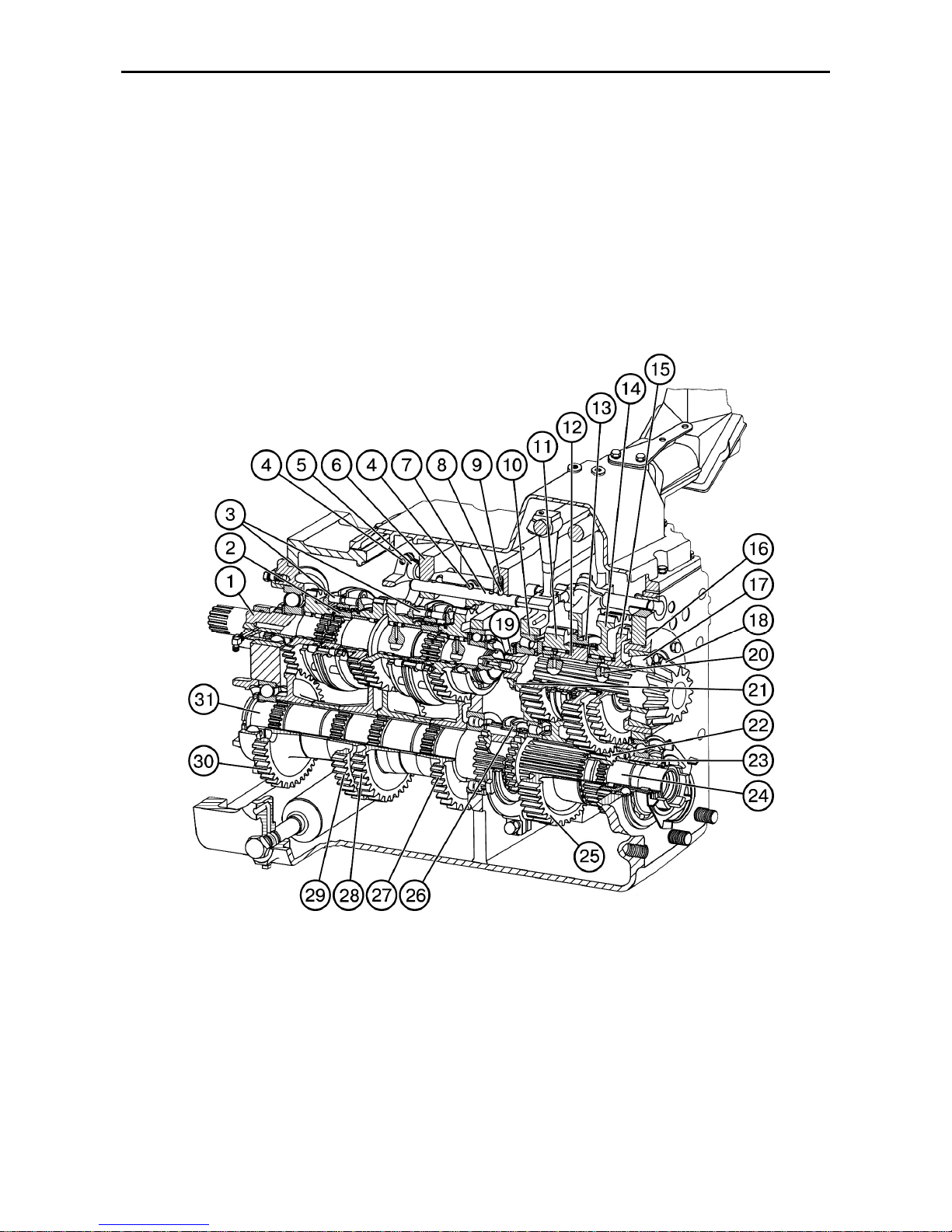
MTZ 1220.1/1220.3 Section D. Construction and Operation
D10
Clutch Housing
The clutch housing accommodates the
drives of the independent PTO, HLL
pump and a pump of the transmission
hydraulic system.
GEARBOX (GB) (16F+8R)
The gearbox (D-12, D-14) - 16/8, is a mechanical fixed-ratio constant-mesh transmission, with 4 forward ranges and 2
backward ranges, with intra-range shift of
gears by means of synchronizers. It provides 16 forward speeds and 8 reverse
speeds as well as driving of the front
drive axle and the synchronous PTO. The
gearbox consists of gearbox housing, a
drive gear assembly, shaft of reduced
speeds and reverse, gear cluster, secondary shaft, control mechanism and hydraulic system
Fig.D-12 GEARBOX
1 – primary shaft; 2, 20 — bushings, 3 — synchronizer; 4 — fork; 5, 7 — dogs; 6 — fork body; 8 — ball; 9 —
spring; 10, 17 — bearings; 11, 14, 15, 22, 23, 25, 27, 28, 29, 30 — pinions; 12 — semi-coupling; 13, 26 —
toothed couplings; 16, 21 — adjusting shims; 18 — secondary shaft; 19 — nut; 24 — gear-cluster shaft; 31
— intermediate shaft.
Page 59
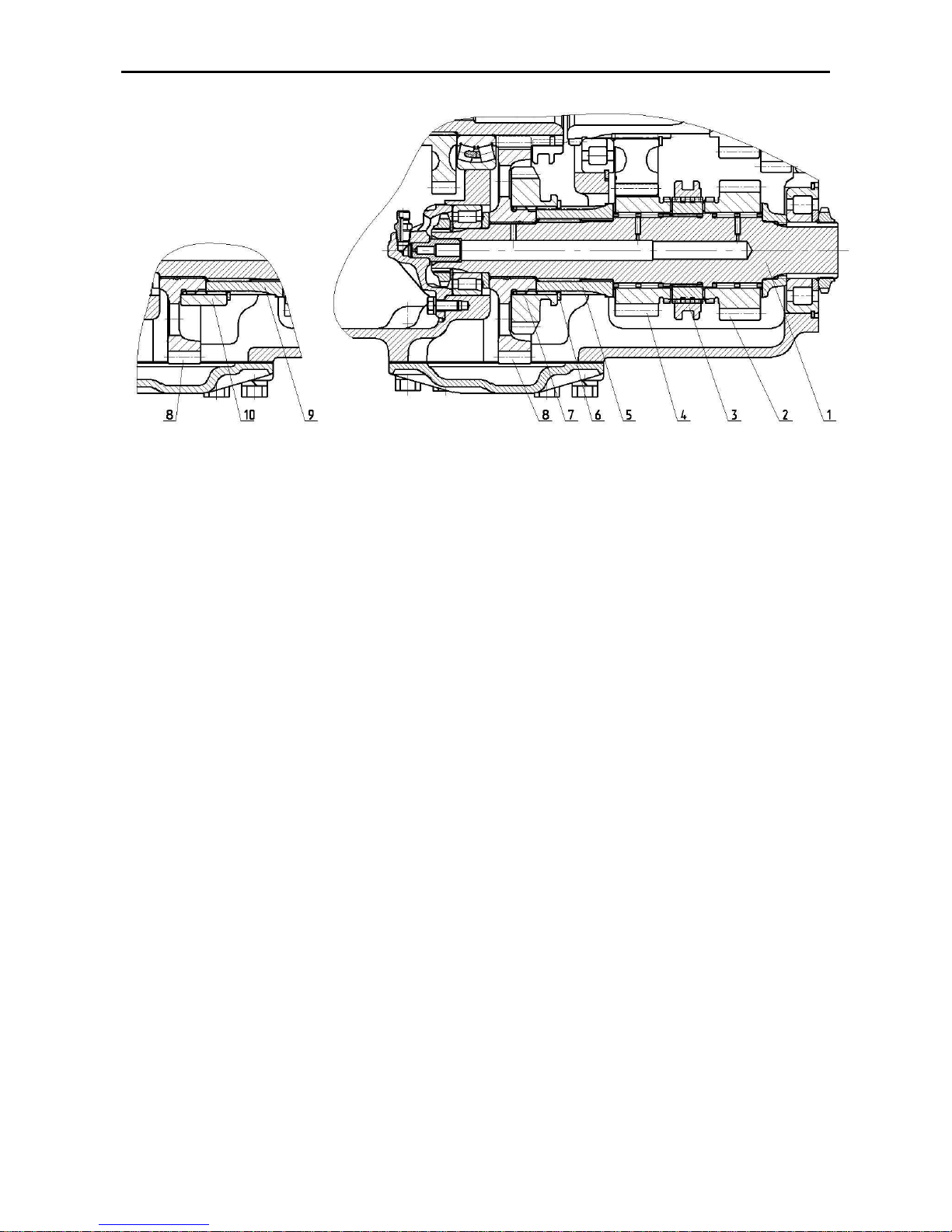
MTZ 1220.1/1220.3 Section D. Construction and Operation
D11
Fig. D-12.2. Shaft of downshift gears:
1 – primary shaft; 2, 4, 7, 8 – gears; 3 – coupling; 5, 9, 10 – bushings; 6 – retaining ring
The drive gear assembly consists of a
primary shaft (1) (Fig.D-12.1) with freeinstalled pinions supported in needle
bearings Two bushings (2) are splined on
the shaft. The bushings carry cone synchronizers (3). The driven gears (27, 28,
29, 30) are fitted on the intermediate shaft
(31) installed in the housing in two bearings with a slight pre-load.
The pinions (22) and (25) are installed on
the splines of the gear-cluster shaft (24).
The back mount of the shaft is located in
the gear hub (23) of the synchronous
PTO drive.
The secondary shaft (18) is supported in
the housing in tapered bearings (10) and
(17).
The driving pinion (24) of the front drive
axle is fixedly fitted on the shaft with a
driven gear (15) supported in bearing on
the pinion hub, semi-coupling and bushing with a driven gear installed thereon.
The pack of parts on the shaft is tightened up with the nut (19).
The gear (4) of the 1st and 2nd ranges and
the gear (2) of the reverse are fitted on
the shaft of downshift gears and reverse
(1) (Fig. E-12.2). The gear (8) is mounted
on the shaft by means of a bronze bushing. Depending on the standard equipment of the gearbox, the design of the
shaft of downshift gears differs as follows:
1) if the gearbox provides for the
possibility of installation of the
speed-reduction gear, the
splined bushing (5) is fitted with
the speed-reduction gear wheel
(7) connected with the splines of
the gear (8) and fixed by means
of the retaining ring (6) on the
bushing (5);
2) if the gearbox does not provide
for the possibility of installation of
the speed-reduction gear, the
splined bushing (9) is fitted with
the bushing (10) connected with
the gear (8) through the splines
and fixed by means of the retaining ring (6) on the bushing (9).
Page 60
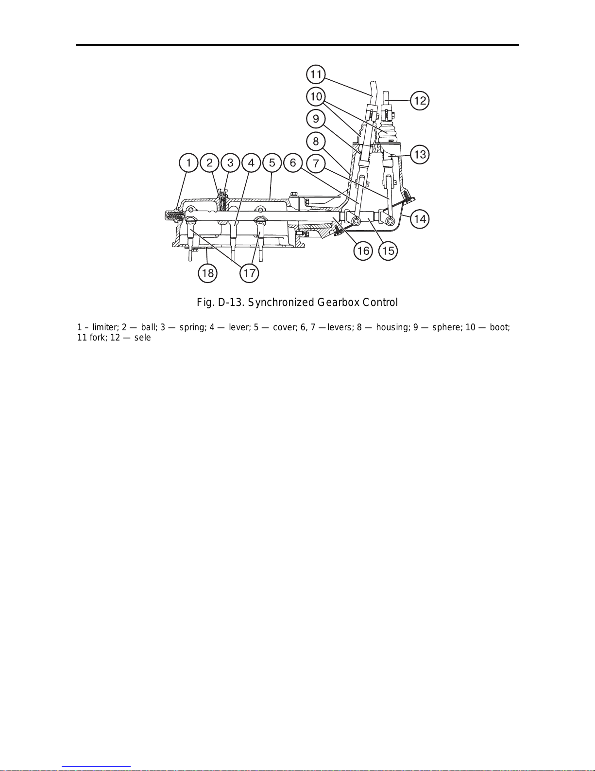
MTZ 1220.1/1220.3 Section D. Construction and Operation
D12
Fig. D-13. Synchronized Gearbox Control
1 – limiter; 2 — ball; 3 — spring; 4 — lever; 5 — cover; 6, 7 —levers; 8 — housing; 9 — sphere; 10 — boot;
11 fork; 12 — selector fork; 13 — spring; 14 — cover; 15, 16 — shafts; 17 — lever; 18 - link.
GB control mechanism
The GB control mechanism (Fig. E-13)
comprises the gear-shift and speed-range
change-over mechanisms. The gear-shift
mechanism is installed in the fork member (6) (Fig. E-12) and in the casings (5)
and (8) (Fig. E-13). The engagement is
achieved through the lever (7), shaft (15)
and arm (4). The dogs (5) and (7) are installed in the fork member (6) (Fig. E-12)
with the forks (4) fixed thereto. To exclude simultaneous engagement of two
speeds, the locking balls are located between the dogs (5) and (7). To hold the
forks (4) in the neutral and engaged posi-
tions, the spring-loaded ball-point locks
(8) are provided.
The speed-range change-over mechanism consists of a fork (11) of the range
change-over handle, lever (6), shaft (16)
and arms (17) located in the bodies (5)
and (8) as well as parts installed in the
transmission gearbox casing.
The toothed couplings (13, 26) (Fig. E-
12.1) and (3) (Fig. E-12.2) are moved by
forks (1, 4, 14) (Fig. E-14) attached on
the dogs (2, 5, 15), respectively. The
toothed couplings (13, 26) (Fig. E-12.1)
and (3) (Fig. E-12.2) are fixed in neutral
and engaged positions by the parts (8,
11, 12) (Fig. E-14).
Page 61
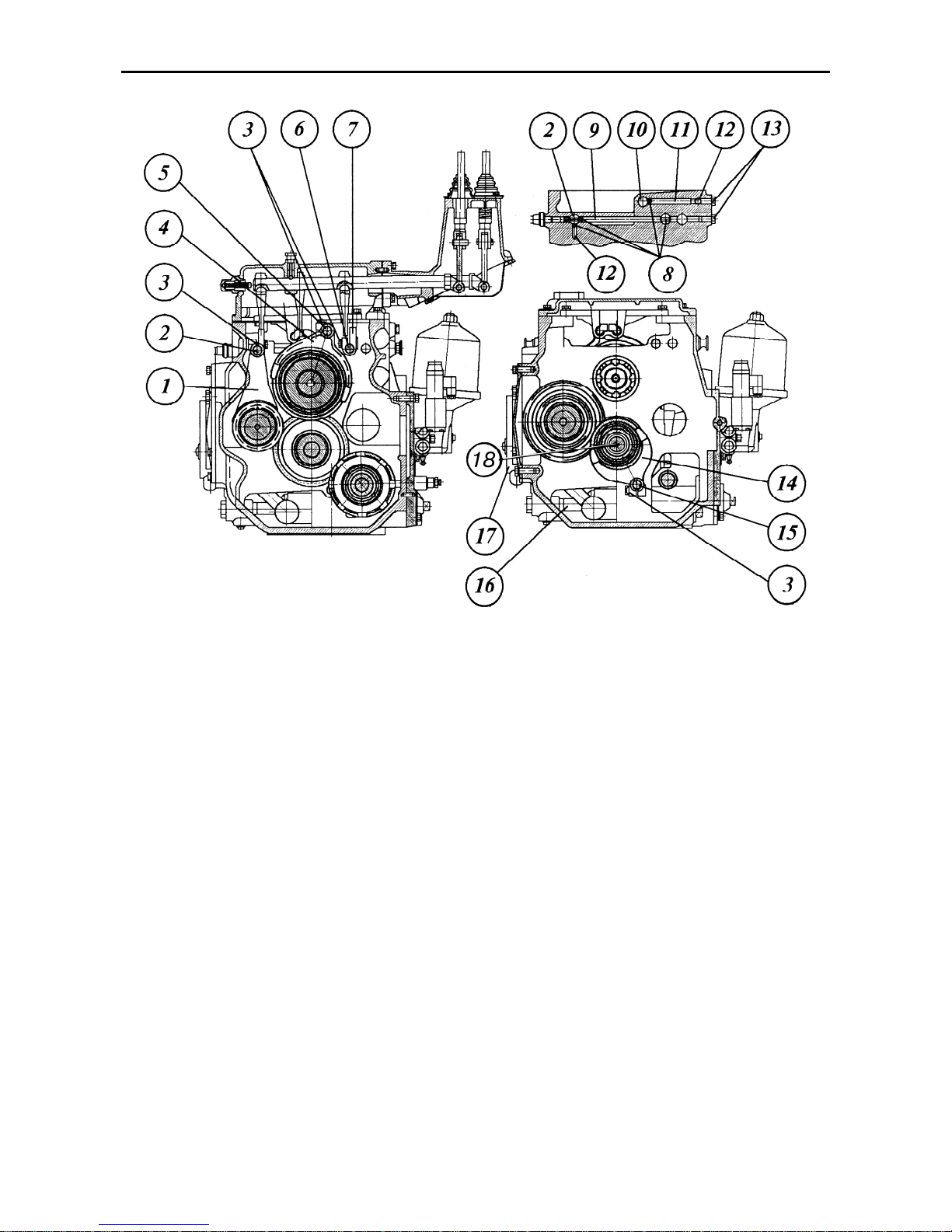
MTZ 1220.1/1220.3 Section D. Construction and Operation
D13
Fig.D-14. Gearbox:
1, 4, 14 – forks; 2, 5, 6, 10, 15 – dogs; 3, 13 – bolts; 7 – dog; 9 – pin; 11 – lock;
12 – spring; 8 – ball; 16 – filter; 17 – pump casing; 18 – inner shaft.
To exclude simultaneous engagement of
the two toothed couplings (26) (Fig. E-
12.1) and (3) (Fig. E-12.2) the locking
balls (8) (Fig. E-14) are installed in holes
in the GB casing (Fig. E-14).
Page 62
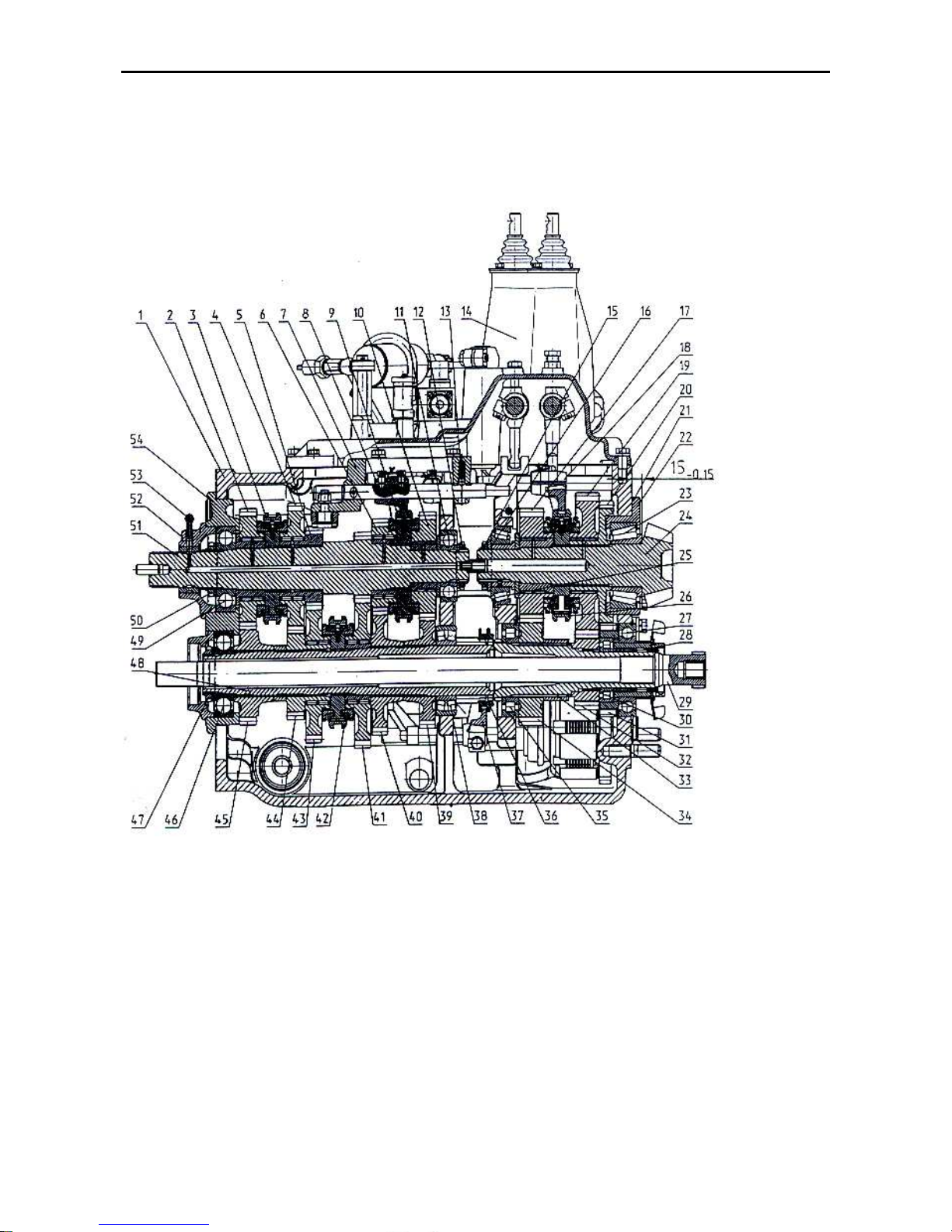
MTZ 1220.1/1220.3 Section D. Construction and Operation
D14
Gearbox (24F+12R) (optionally) The gearbox consists (Fig. D-15.1) - mechanical, fixed-
ratio, range-type - of a transmission assembly, a shaft of reduced gears and reverse, a
secondary shaft supported in bearings in the housing as well as a control mechanism and
hydraulic system units.
Longitudinal section of the gearbox:
1 – housing; 2, 4, 5, 6, 10, 17, 19, 20, 31, 32, 34, 39, 40, 41, 43, 44, 45 – gears; 3, 9, 26, 42 – synchronizers;
7 – fork box; 8, 18, 37 – forks; 11, 23, 25, 27, 28, 30, 35, 38, 46, 49 – bearings; 12, 15, 47, 50 – nuts; 13 –
ball-point lock; 14 – control mechanism; 16, 21 – adjusting shims; 22 – bearing seat; 29 – independent PTO
drive shaft; 33 – gear cluster shaft; 36 – toothed coupling; 48 – intermediate shaft; 51 – primary shaft; 52 –
lubricant feed sleeve; 53 – oil pipeline;
Page 63
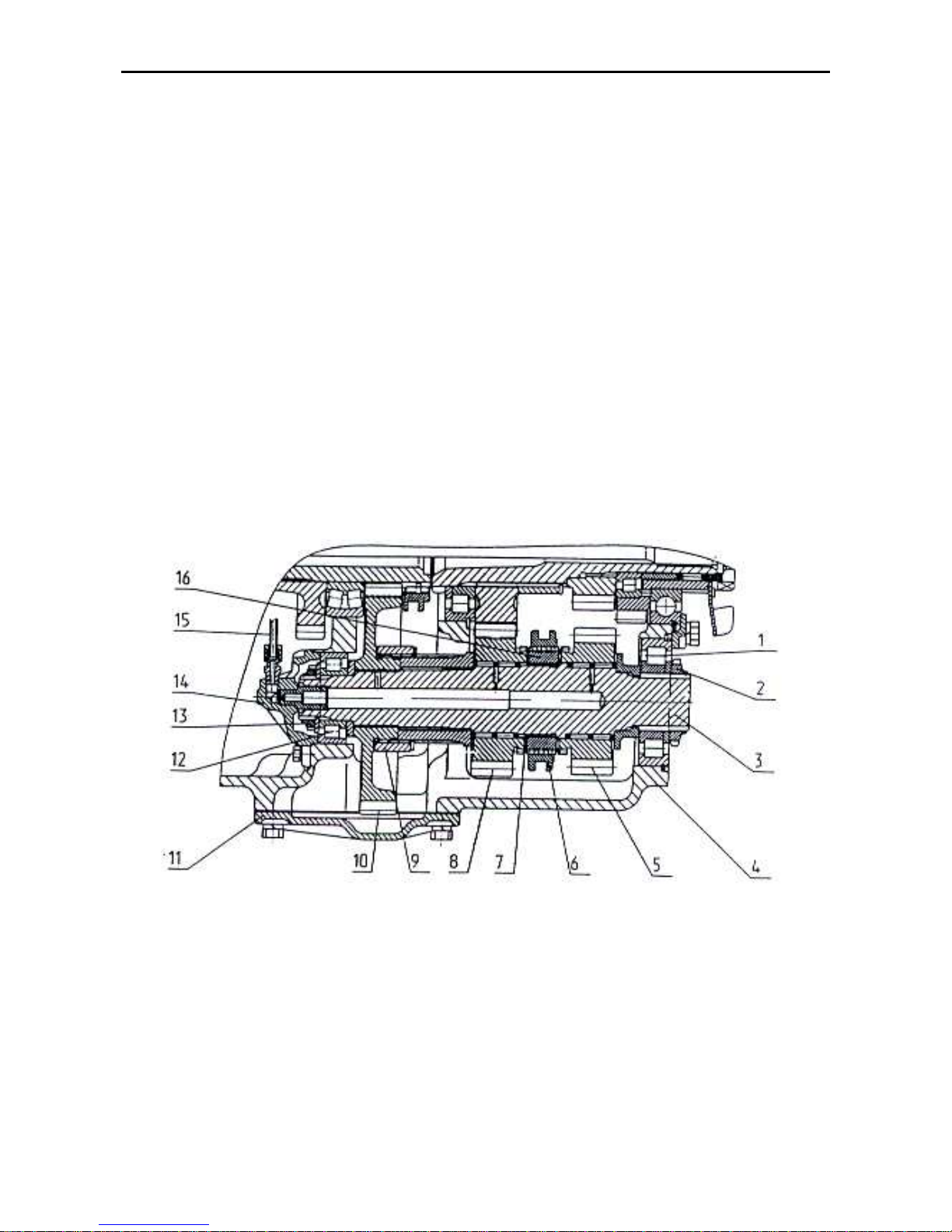
MTZ 1220.1/1220.3 Section D. Construction and Operation
D15
The speed-gear assembly is mounted
on the cover (54) and consists of the primary shaft (51) with driving pinions (2, 4,
6, 10) mounted in needle bearings riding
thereon. These pinions ensure engagement of the 5th, 6th, 3rd and 4th gear, respectively. The driving pinion of the 1st
gear is made integral with the shaft (51)
and the driving pinion of the 2nd gear is
fixed rigidly on the shaft. The needle
bearings are force-lubricated through the
oil pipeline (53) and holes drilled in the
shaft. The male splines of the shaft carry
two inertia-type synchronizers (4) and (9);
the latter effect engagement of the 5th, 6th,
3rd, and 4th gears. The primary shaft rests
on ball bearings mounted in the cover
(54) and casing (1).
The intermediate shaft (48) carries the
press-fitted driven pinions (54, 40 and 39)
of the 5th, 6th, 3rd and 4th gear, respectively. The driven pinions (43 and 41) of
2nd and 1st gears, respectively, rest on
needle bearings. An inertia-type synchronizer (42) to help engagement of the 1st
and 2nd gears.
The downshift and reverse gear shaft 3
(see Fig. E-15.2) is mounted in the body
(4) and rests on bearings (1 and 12). The
shaft also carries a driven pinion (10)
which is coupled to the shaft through
bushings (9), forward driving pinion (8)
and reverse pinion (5) running in needle
bearings. These pinions are coupled with
the shaft through a toothed coupling (6).
Bushing (16) which sits on male splines
of the shaft is locked on the shaft by
means of a retaining ring (7).
Fig. D-15.2 Downshift and reverse gear shaft:
1, 12 – bearings; 2, 13 – nuts; 4 –casing; 5, 8, 10 –pinions; 6 – toothed coupling; 7 – retaining ring; 9 – bush-
ing; 11 – cover; 14 – oil delivery cup; 15 – oil pipeline; 16 – bushing
Page 64
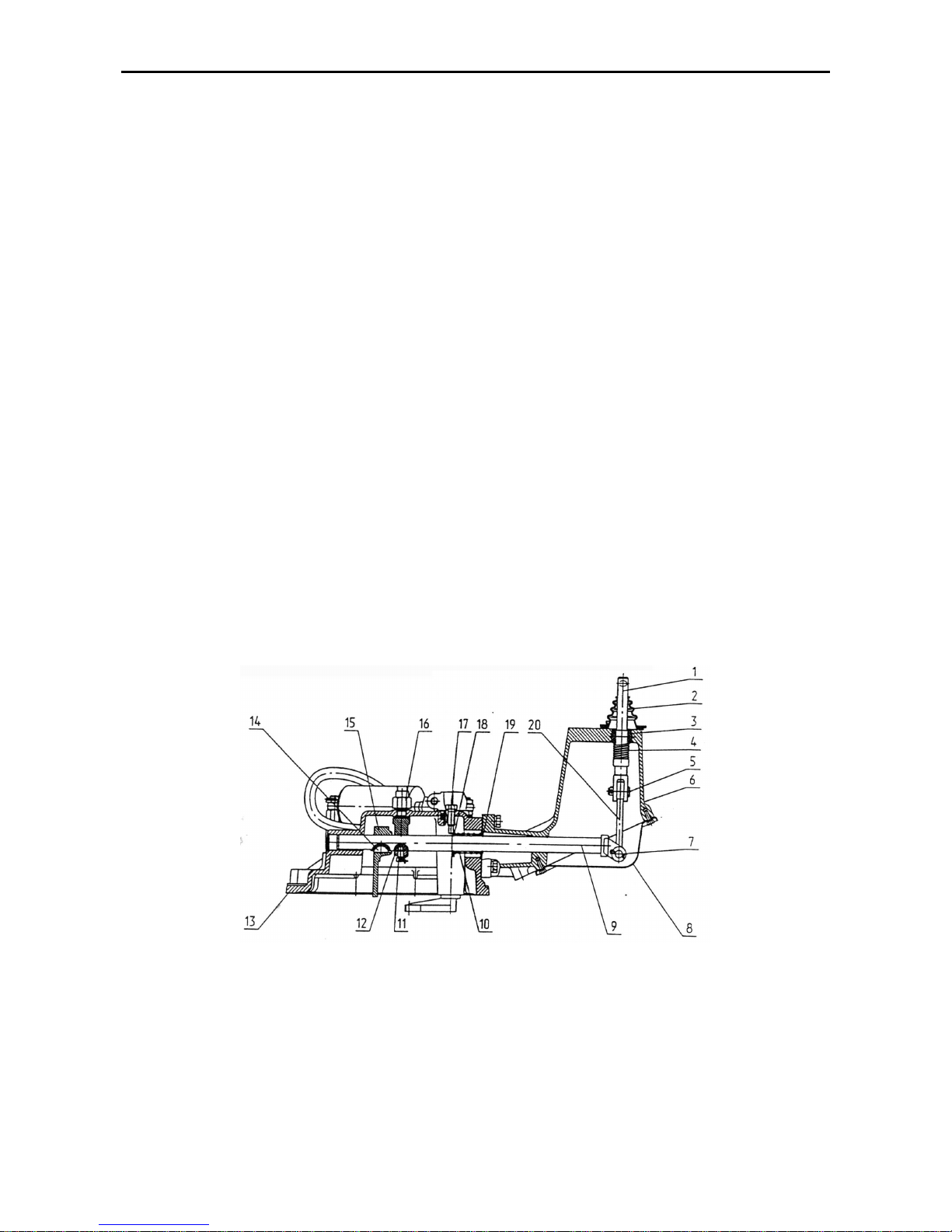
MTZ 1220.1/1220.3 Section D. Construction and Operation
D16
The gear-cluster shaft 33 (see Fig. E-
15.1) is installed in the casing (1) and
rests in bearings (27) and (35). Gears
(32) and (34) are splined-mounted on the
shaft and locked with retaining rings. The
PTO driven pinion (31) is mounted on the
shaft in roller bearings (28) and (30).
The secondary shaft 24 (see Fig. E-
15.1) is installed in the body (1) in tapered bearings (23) and (25). The bearings are adjusted by shims (16), while the
position of the shaft bevel pinion relative
to the body end-face (size 15
-0.15
) is adjusted through selection of the adjusting
shims (21). The FDA and synchronous
PTO drive pinion (20) and the synchronizer (26) boss are rigidly fixed on the
shaft. The driven pinions (17) and (19)
rest in needle bearings; the latter are
force-lubricated through the holes drilled
in the shaft. The shifting between the pinions is made with the locked-on-dog fork
(18) by means of the synchronizer (26).
The dog is installed in a recess in the
casing (1) and fixed with a ball-point lock.
The sets of components on the primary,
intermediate, secondary as well as downshift-and –reverse gear shafts are tightened up by nuts (12, 15, 47 and 50).
Transmission Gearbox Control
Mechanism
The transmission gearbox mechanism
comprises a gear-shift mechanism and a
speed-range change-over mechanism
with an electro-hydraulic system of
change-over between high “H” and lower
“L” stages of the GB reduction gear.
The gear-shift mechanism (Fig. E-15.3)
is mounted in the speed-gear assembly,
fork member (7) and the control mechanism (14) cover (see Fig. E-15.1).
The cover (54) (Fig. E-15.1) houses the
dogs with shifting forks of 1st, 2nd and 5th,
6th gears fastened thereto. The dogs are
fixed in the cover with ball-point locks.
The position of forks on the dogs is adjusted by means of tapered screws
Fig. D-15.3. Gear-shift mechanism:
1 – fork; 2 – boot; 3 – sphere socket; 4 – spring; 5, 7 – pins; 6 – casing; 8 – cover; 9 – shaft; 11 – bolt; 12 –
bushing; 13 – cover; 14 – key; 15, 20 – levers; 16 – pick-up; 17 – screw; – 18 – washer; 19 – retaining ring
Page 65
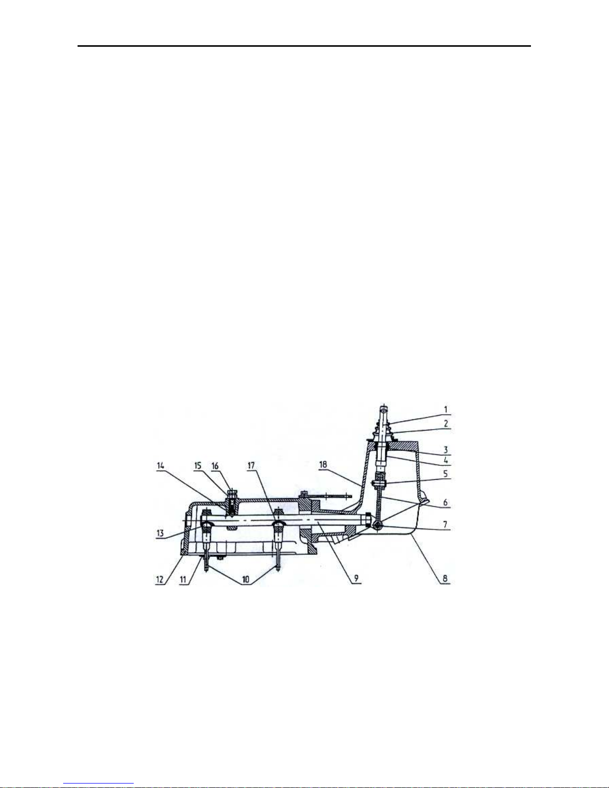
MTZ 1220.1/1220.3 Section D. Construction and Operation
D17
Three dogs, a fork (8), ball-point lock (13)
and parts of the two gear engagement
lockout mechanism are installed in the
fork assembly (7). The member is attached to the transmission gearbox casing (1).
The shaft (9) with the arm (15) and bushing (12) fitted thereon is installed in the
supports of cover (13) and casing (6) (see
Fig. E-15.3). The two bushings (18) and
spring (10) are installed between the retaining rings (19). The bushing end-faces
abut the screw (17) and the casing (6)
end-face. This arrangement serves to set
the gear-shift lever to neutral. The shaft
(9) is coupled with fork (1), with the gearshift lever fixed thereto through the pins
(5 and 7) and lever (20). The fork (1) is
located in the casing (6), in the sphere
socket (3) and spring-loaded with the
spring (4).
The speed range change-over mecha-
nism (Fig. E-15.4) is installed in the
transmission gearbox casing (1) and
cover of the gear-shift mechanism (14)
(see Fig. E-15.1).
In the casing (1), the fork (37) for changing-over the toothed coupling (36), the
fork for changing-over the toothed coupling (6) (see Fig. E-15.2) and the fork
(18) for changing-over the synchronizer
(26) (see Fig. E-15.1) are mounted on the
dogs. The dogs are locked in the body
with ball-point locks.
In the control mechanism (Fig. 15.4), the
shaft (9) together with arms (10) keyed
thereto rests in the supports of cover (12)
and housing (18). The shaft (9) is locked
with a ball-point lock (14) and is connected to fork (1) with attached speedrange change-over lever by means of
pins (5 and 7). The fork (1) is located in
the casing (18), in the sphere socket (3)
and preloaded with spring (4).
Fig. D-15.4. Speed-range change-over mechanism:
1 – fork; 2 – boot; 3 – sphere socket; 4 – spring; 5, 7 – pins; 6, 10 – levers; 8 – covers; 9 – shaft; 11 – link;
13, 17 – keys; 14 – ball-point lock; 15 – nut; 16 – bolt; 18 – casing.
Page 66
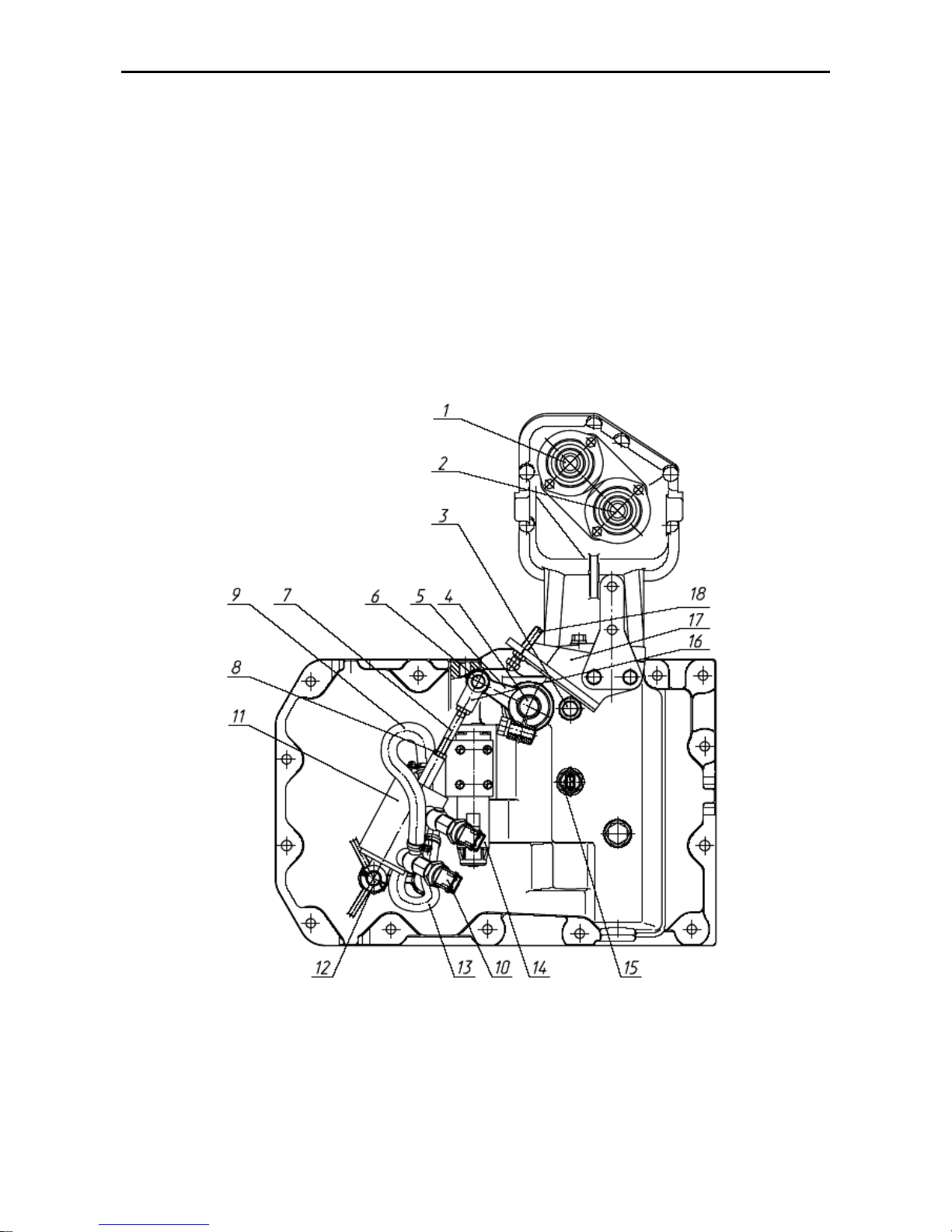
MTZ 1220.1/1220.3 Section D. Construction and Operation
D18
The high-to-low reduction gear stage
switch-over mechanism of the transmission gearbox (Fig. E-15.5) is
mounted on the gear-shift mechanism
cover and consists of a cylinder (11) fixed
on the axle (12), pusher (7) and lever (5)
mounted on the roller (4). The fork (16) is
connected with the lever (5) by means of
the pin (6). The lever of the roller (4)
meshes with the dog of the fork (18) (Fig.
E-15.1) and forces the synchronizer (26)
coupling to move as the roller rotates.
The position of lever (5) is adjusted by
changing the length of the pusher (7) with
further locking by a check-nut (8). The
cylinder (11) communicates with the hydraulic system through an electrohydraulic valve (14). The sensor (15)
connects the valve (14) to the electric circuit when the gear-shift lever is in its neutral position, only. The drawn-in position
of the cylinder corresponds to the lower
“L” stage of the transmission gearbox reduction gear. Pressure-sensitive pick-ups
(10) serve to indicate the engaged state
of the reduction gear.
Fig. D-15.5. High-to-low reduction gear stage switch-over mechanism:
1 – gear-shift fork; 2 – speed range change-over fork; 3 – bolt; 4 – roller; 5 – lever; 6 – pin; 7 – pusher; 8 –
check-nut; 9, 13 – oil pipelines; 10 – pressure-sensitive pick-up; 11 – hydraulic cylinder; 12 – axle; 14 – elec-
tro-hydraulic valve; 15 – sensor, 16 – fork, 17 – bracket, 18 – adjusting screw.
Page 67
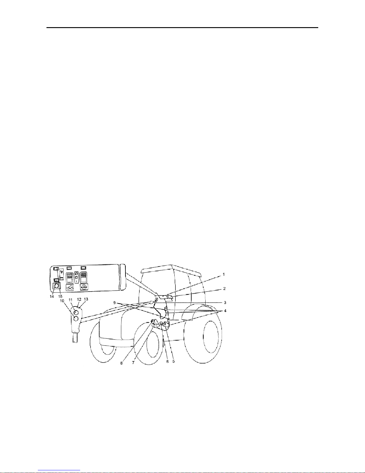
MTZ 1220.1/1220.3 Section D. Construction and Operation
D19
Transmission Gearbox Reduction Gear
Control System
The electro-hydraulic control system
(Fig. E-15.6) involves a control panel (1)
located in the tractor cab to the right of
the driver, a gear-shift and reduction gear
stage switch-over lever (3), GB neutral
pickup (5), sensors (7 and 8) mounted on
the reduction gear switch-over hydraulic
cylinder (11) (Fig. E-15.5), electrohydraulic distributor (6) located atop of
the transmission gearbox cover, and connecting cables (4) with terminal blocks
(9). The system is supplied with power
from the on-board power system through
a fuse block (2). Voltage is applied following the engine start-up.
The handle of the lever (3) contains the
pushbuttons (10 and 11) and indicators
(LEDs) (13, 12) to signal the high or low
reduction gear stage ON-state, respectively.
The panel (1) contains also the indicators
(15 and 14) to signal the ON-state of the
high or low reduction gear stage and reduction gear control relay.
The system allows the reduction gear
stages to be switched over when the
lever (3) is in its neural position only (contacts of the transmission gearbox neutral
position pickup (5) are closed).
Signals are applied to sensors (13, 12)
and (15, 14) from respective pressuresensitive pickups (8, 7).
Following the engine start-up, the default
setting is the reduction gear low stage
ON. In this case, the LED indicators (13,
15) should be on.
Switch over to the reduction gear high
stage is to be effected by depressing the
pushbutton (11). Now, the LED indicators
(13, 15) should go off, while LEDs (12,
14) turn on.
Switching over from high to low stage is
achieved be depressing the pushbutton
(10).
The control system circuit diagram for the
GB reduction gear, DL and FDA control is
given at the end of the “Manual”.
ATTENTION! The reduction gear stages shall be
only changed-over from the
lower stage to the higher
one and vice versa when
the tractor is fully stopped.
Fig. D-15.6
1 – control panel; 2 – fuse box; 3 – gear-shift and reduction gear stage switch-over lever; 4 – connecting cables; 5 – transmission gearbox neutral position pickup; 6 – reduction-gear electrical distributor; 7 – higher
stage pressure pickup; 8 – lower stage pressure pickup; 9 – terminal blocks; 10 – lower stage switch-on
pushbutton; 11 – higher stage switch-on pushbutton; 12 – higher stage LED indicator; 13 – lower stage LED
indicator; 14, 15 – pilot lamps.
Page 68
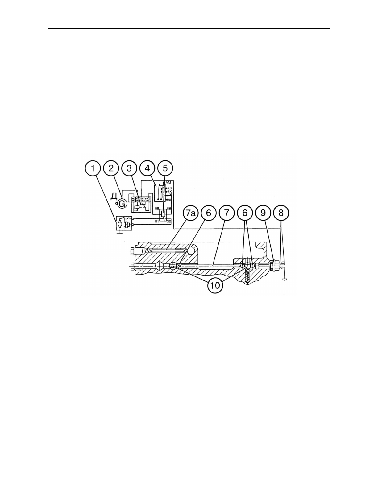
MTZ 1220.1/1220.3 Section D. Construction and Operation
D20
Engine Starting Interlock
As a precautionary measure against the
engine starting when the range is
switched on, the tractor is equipped with a
special interlock device (Fig. E-15.7). The
interlock consists of a switch (8) located in
the transmission gearbox casing on the
left side, balls (6) and pins (7, 7).
On switching the range on, the interlock
mechanism opens the switch contacts and
breaks the circuit of the starter intermediate relay (1).
The shims (9) are provided to adjust the
instant of contact opening (9).
ATTENTION! Before proceeding to
starting the engine, set the transmission
gearbox speed-range change-over lever
to its neutral position!
Fig. D -15.7. Diagram of interlocking the engine starting:
1 – starter; 2 – alternator; 3 – interlock relay; 4 – starter switch; 5 – starter relay; 6 – interlock mechanism
balls; 7 – pin; 7a – lock; 8 – unlock switch; 9 – adjusting shims; 10 – range switch-over dogs
Page 69
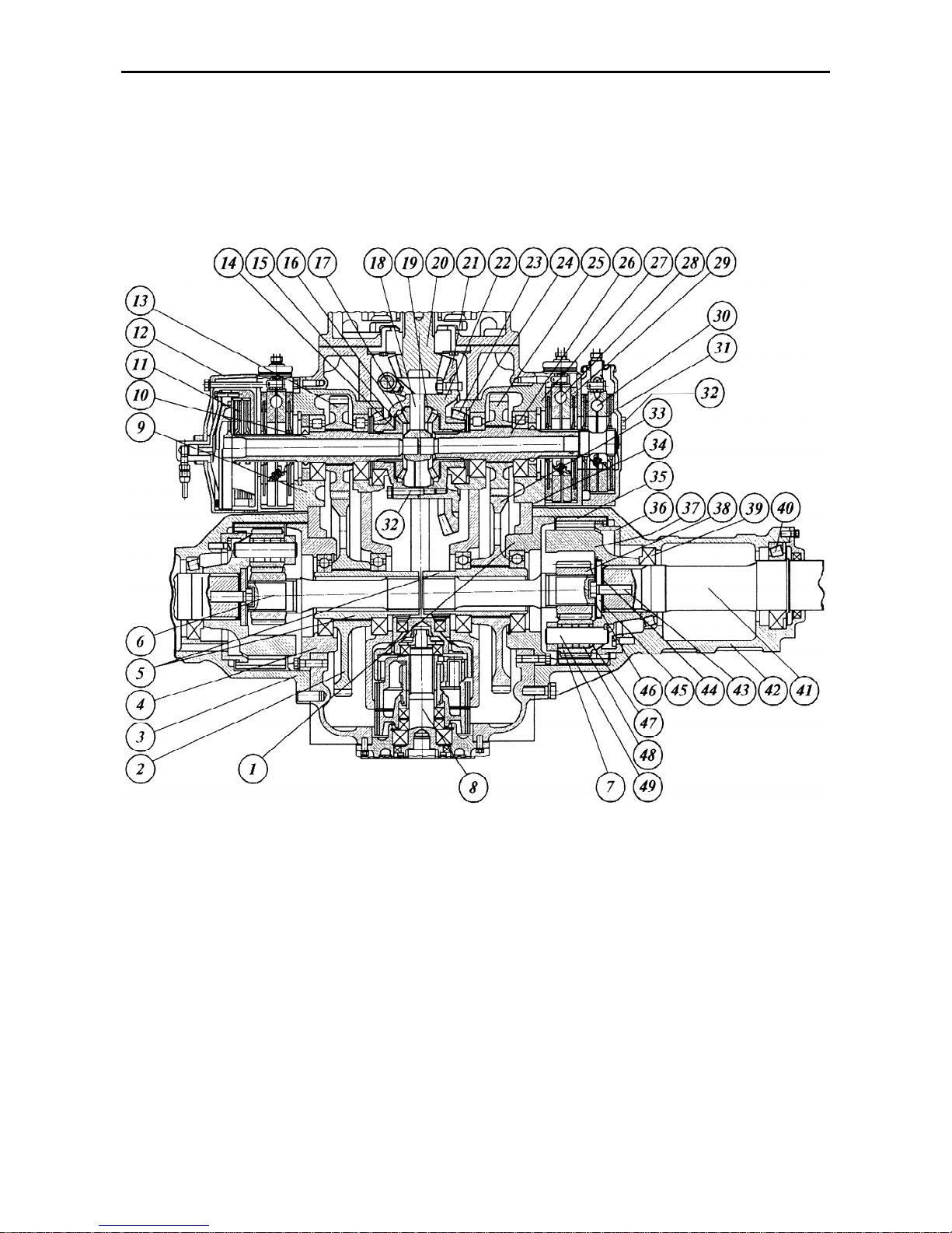
MTZ 1220.1/1220.3 Section D. Construction and Operation
D21
Rear Axle
The rear axle (Fig. E-16) consists of the
final drive, differential assembled with a
hydraulically-driven friction clutch used for
locking, hub drives located in the rear axle
housing, and the will transmission assemblies located in the half-axle housings.
Fig. D-16. Rear axle:
1, 4, 9, 27 – bearing bodies; 2 – hub-drive gear; 3 – left-hand half-axle housing; 5 – hub-drive gear bushings;
6 – torsion bar; 7 – differential pinion; 8 – PTO; 10 – left-hand hub-drive pinion shaft; 11 – differential lock
clutch; 12 – differential lock housing; 13 – hub-drive pinion; 14 – half-axle gear bearing washer; 15 – halfaxle gear; 16 – differential cover; 17 – differential pinion; 18 – differential spider; 19 – spherical washer; 20 –
final drive pinion; 21 – final drive gear; 22 – differential case; 23 – bearing; 24 – thrust ring; 25 – hub-drive
pinion; 26 – right-hand pinion shaft; 28 – service brake; 29 – service brake housing; 30 – parking brake; 31 –
parking brake housing; 32 – bolt; 33 – hub-drive gear; 34, 44 – adjusting shims; 35 – crown gear; 36 – crown
gear hub; 37 – cage; 38 – sun gear; 39, 40 – bearings; 41 – half-axle; 42 – right-hand half-axle; 43 – bolt; 45
– thrust washer; 46 – arresting plate; 47 – washer; 48 – rollers; 49 – differential pinion axle.
Page 70

MTZ 1220.1/1220.3 Section D. Construction and Operation
D22
Final Drive
The final drive of a bevel circular-arc teeth
type consists of a final-drive bevel pinion
(20), which is integral with the transmission gearbox secondary shaft, and a final
drive gear (21), the latter being bolted to
the differential case (22).
Differential
The differential of the closed lockable
bevel-pinion type consists of the case (22)
and cover (16) fastened together by
means of the bolts (32), four differential
pinions (17) together with spherical washers (19) and two thrust washers (14). The
differential case is installed as an assembly in the rear-axle housing in two roller
bearings (23). To lock the differential, the
hydraulically-controlled friction multipledisk clutch (Fig. E-17) which interlocks the
cross and the differential pinions with the
left-hand half-axle gear of the differential.
Hub Drives
The hub drives consist of two pairs of
straight spur pinions and gears (13, 2) and
(25, 33) (Fig. E-16).
The hub-drive pinions (13, 25) are
mounted in the splines of shafts (10, 26)
which are running in roller bearing bodies.
The differential is locked axially by means
of the bearings (23).
The shafts (10) and (26) link the half-axle
gears (15) with the hub-drive pinions and
the brake disks through their spline joints.
The hub-drive gears (2, 33) are mounted
on splined bushings (5) which are
mounted on ball bearings.
The adjusting shims (34) with the thickness of 0.2 mm and 0.5 mm are inserted
between the flanges of the bearing bodies
(9, 27) and the rear axle housing for adjustment of the axial clearance in the
bevel roller bearings (23) and backlask in
the final drive pinion-to-gear (20), (21)
pair. The bevel roller bearings shall be so
adjusted that the torque needed for turning the differential would be 5 to 8 N-m.
The backlash in the final drive shall be
within the range 0.20…0.55 mm.
Wheel Transmissions
The wheel transmissions are made up of
two straight-spur planetary trains, located
in the half-axle housings (3, 42), torsion
bars (6) made with splines which link the
hub-drive gears (2, 33) with the abovementioned planetary trains through
splined bushings (5).
The planetary train consists of a fixed
crown gear (35) mounted on the boss (36)
and bolted to the housing (42); carrier
(37); sun gear (38) seated on the splines
of torsion bar (6) and four differential pinions (50) running on the rollers (48) of the
axles (49).
The half-axle bearings (39, 40) are adjusted by formation of stocks of shims (44)
with the thickness of 0.2-mm and 0.5 mm.
Page 71
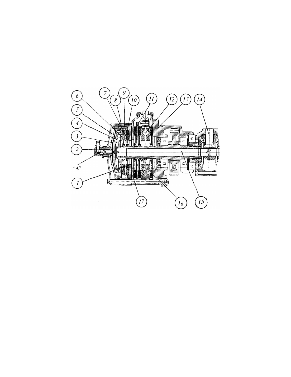
MTZ 1220.1/1220.3 Section D. Construction and Operation
D23
Differential Lock Clutch and Three-Disk Service Brake
The multiple-disk hydraulically controlled
differential lock clutch (1) (Fig. E-17) is located in casing (8) which is bolted to the
rear axle housing through the housing of
the left-hand three-disk brake and the
bearing body. The three-disk dry service
brake housing (17) contains the brake
disks (16), pressure disks (13), intermediate disk (11), balls (15) and brake release
springs (not shown).
Fig. D-17. Differential lock clutch:
1 – lock clutch; 2 – adapter; 3 – diaphragm cover; 4 – pressure disk; 5 – diaphragm; 6 – release disk; 7 –
intermediate disk; 8 – housing; 9 – clutch body; 10 – locking; 11 – brake intermediate disk; 12 – ball; 13 –
pressure disk; 14 – differential spider; 15 – lock-up shaft; 16 – brake disk; 17 – left-hand three-disk brake
housing.
The clutch consists of lock-up shaft (15)
which is spline-coupled with the differential spider (14), body (9), pressure disk
(4), release disk (6), diaphragm (5), cover
(3), adapter (2) and disks (10) splinemounted on the left-hand wheel transmission pinion.
Under the action of oil delivered under
pressure to the rod-end chamber “A” from
the ADL control hydraulic system, the
diaphragm (5) in conjunction with the
pressure disk (4) moves and presses
disks (10) against the bearing surfaces of
the clutch body (9), intermediate disk (7)
and release disk (6) so that the differential (the differential spider with the lefthand half-axle gear) gets locked. When
the front wheels turn to a certain degree
from the straight-line motion, the rod-end
chamber “A” opens to the discharge line,
and the differential unlocks.
Page 72
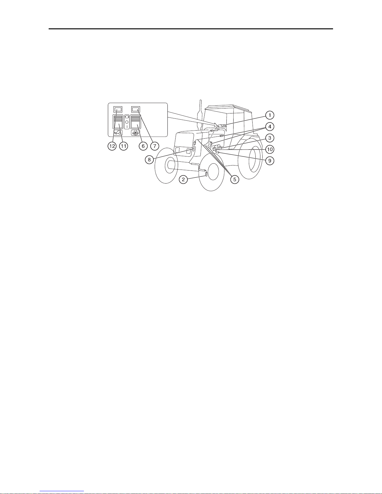
MTZ 1220.1/1220.3 Section D. Construction and Operation
D24
Automatic Differential Lock-Up (ADL)
The ABD feature is designed to improve
the tractor traction and adhesion properties and off-road capability. It consists of a
two-disk hydraulically operated lock-up
clutch (Fig. E-17) and an electro-hydraulic
control system. The latter ensures two operation modes: “automatic” and “forced”.
Fig. D-18. Rear axle differential lock and FDA drive control system:
1 – control panel; 2 – steering wheel turning angle sensor; 3, 10 – control electro-hydraulic distributors for
the DL and the FDA drive, respectively; 4 – terminal blocks; 5 – connecting cable; 6 – DL control key; 7, 12 –
indicator lamps; 8 – loop; 9 – automatic FDA drive control sensor; 11 – FDA drive control key
The electro-hydraulic DL control system of
the rear axle (Fig. E-18) is composed of a
panel (1), turning angle sensor (2) of
steering wheels; installed on the left-hand
FDA reduction gear, DL control electrohydraulic distributor (3) located on the
right-hand GB cover and coupled through
an oil pipeline with the DL clutch, and
connecting cables (5) with terminal blocks
(4). The system is supplied with power
from the on-board electrical circuit via a
safety fuse in the fuse box installed in the
dashboard. The system is powered after
starting the engine. The key (6) for controlling the DL control and DL indicator
lamp (7) are installed on the panel (1)
face. The latter is located over the righthand side tractor control panel.
How to Use the Rear Axle DL Control
Key (6)
1. When performing jobs with great
amount of relative slippage of the rear
wheels, depress the upper part of the
key (6) (fixed position), thus, activating
the automatic mode of differential lockup. Now the electromagnet of the DL
control electro-hydraulic distributor (3)
is energized, the electro-hydraulic distributor spool valve moves and disconnects the lock clutch from the discharge
line and connects it with the feed port.
Then, the lock-up clutch operates and
interlocks the differential and the rear
wheels. The differential is unlocked
automatically when the steering wheels
turn to a certain degree.
2. If a short-time interlocking of the rear
wheels is necessary, including occasions of turning, press the lower part of
the key (6) and hold it in this depressed
position. When released, the key (6) returns to its middle, fixed position, and
differential interlock unlocks.
.
Page 73
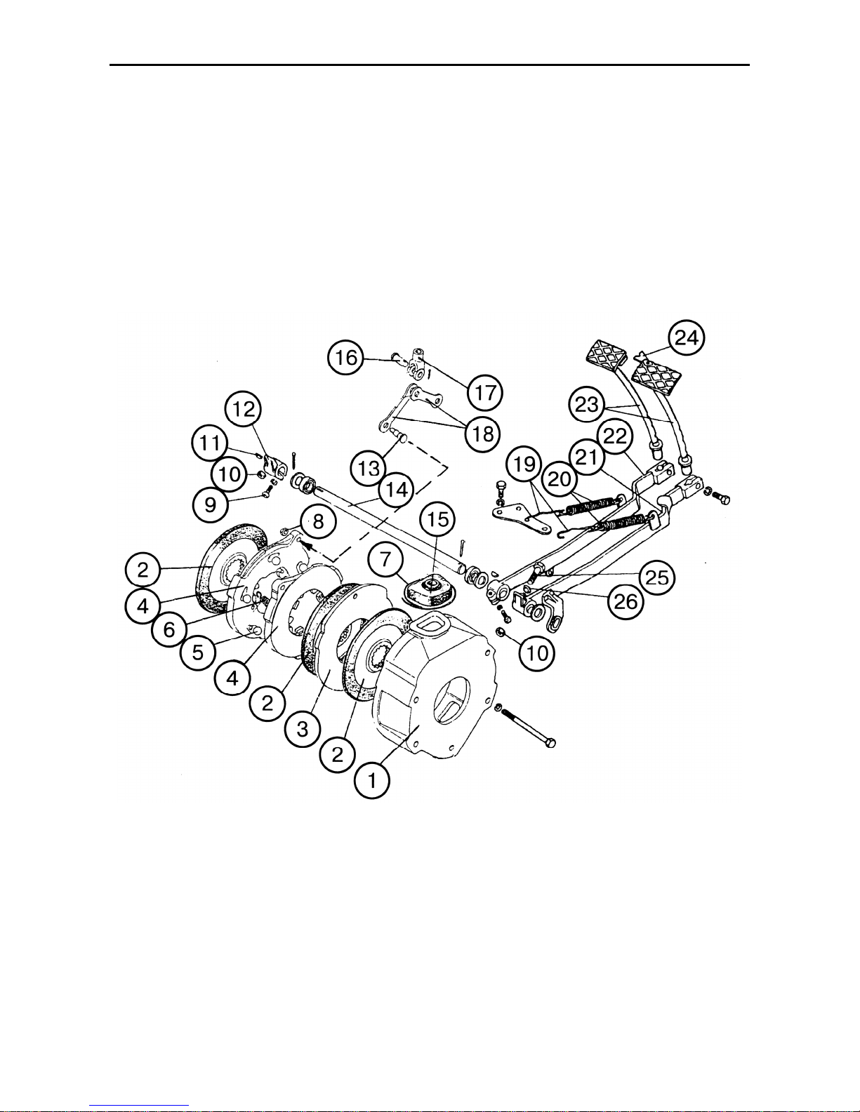
MTZ 1220.1/1220.3 Section D. Construction and Operation
D25
Service Brakes (MTZ-1221.2/1221.3)
The tractor is equipped with three-disk
dry brakes of an increased standard size.
The disks of the left- and right-hand
brakes (2) (Fig. E-20) are spline-mounted
on the rear axle hub drive pinions. The
brakes consist of housings (1), friction
disks (2), pressure disks (4), balls (5) and
contraction springs (6).
The brake actuator is of mechanical type.
Each brake is activated by a separate
pedal (23).
To brake both wheels at the same time,
interlock of the pedals with a latch strip
(24). When the right-hand brake pedal is
depressed, the stop-signal lamps light up.
Fig. D-20. Service brakes and their controls (exploded view):
1 – housing; 2 – brake disk; 3 – intermediate disk; 4 – pressure disk; 5 – ball; 6 – spring; 7 – wire; 8 – nut; 9
– bolt; 10 – check nut; 11 – key-tongue; 12 – lever; 13 – pin; 14 – axle; 15 – boot; 16 – pin; 17 – fork; 18 –
tie-rod; 19 – hooks; 20 – contraction spring; 21, 22 – lever; 23 – stem with pad (pedal); 24 – latch strip; 25 –
adjusting bolt; 26 – spherical washer
Page 74
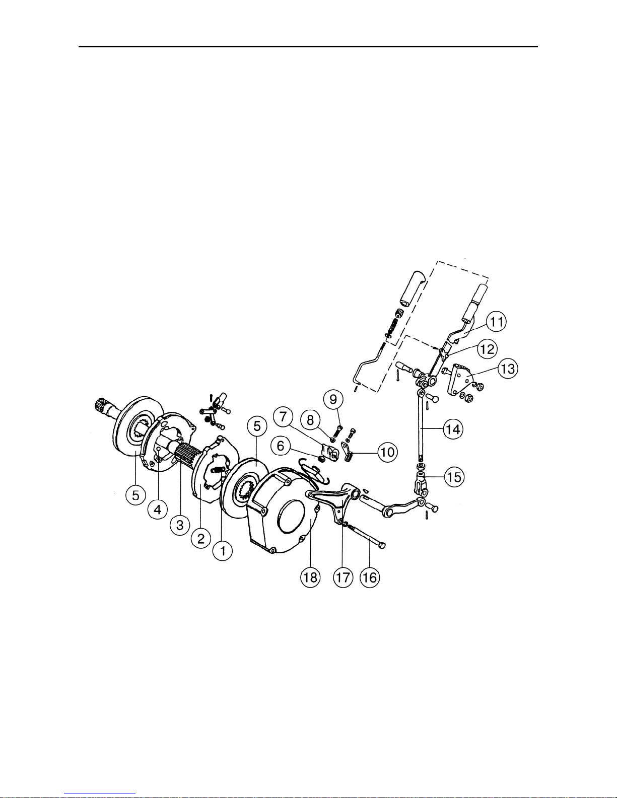
MTZ 1220.1/1220.3 Section D. Construction and Operation
D26
Parking brake
The tractor is equipped with a dry two-disk
parking brake of reduced standard size
(with the diameter of 178 mm), attached to
the housing of the right-hand service
brake. The brake disks (5) (Fig. E-21) are
mounted on the splines of the shaft (3) located inside the right-hand hub-drive pinion shaft and is connected to the rear-axle
differential spider.
The parking brake is applied with the help
of lever (11) placed on the right-hand wall
of the cab. The lever is locked when set to
work by means of a stop catch (12) on the
toothed sector (13).
With the parking brake applied, the differential spider interlocks with the rear axle
housing through the shaft (3), pressure
disks (2), brake disks (5), and casing (18).
Fig. D-21. Parking brake structure and control:
1 – spring; 2 – pressure disk; 3 – shaft; 4 – ball; 5 – brake disk; 6 – check-nut; 7, 11 – lever; 8 – spherical
washer; 9 – adjusting bolt; 10 – brake cock drive lever; 12 – stop catch; 13 – sector; 14 – tie-rod; 15 – fork;
16 – bolt; 17 – bracket; 18 – case
Page 75
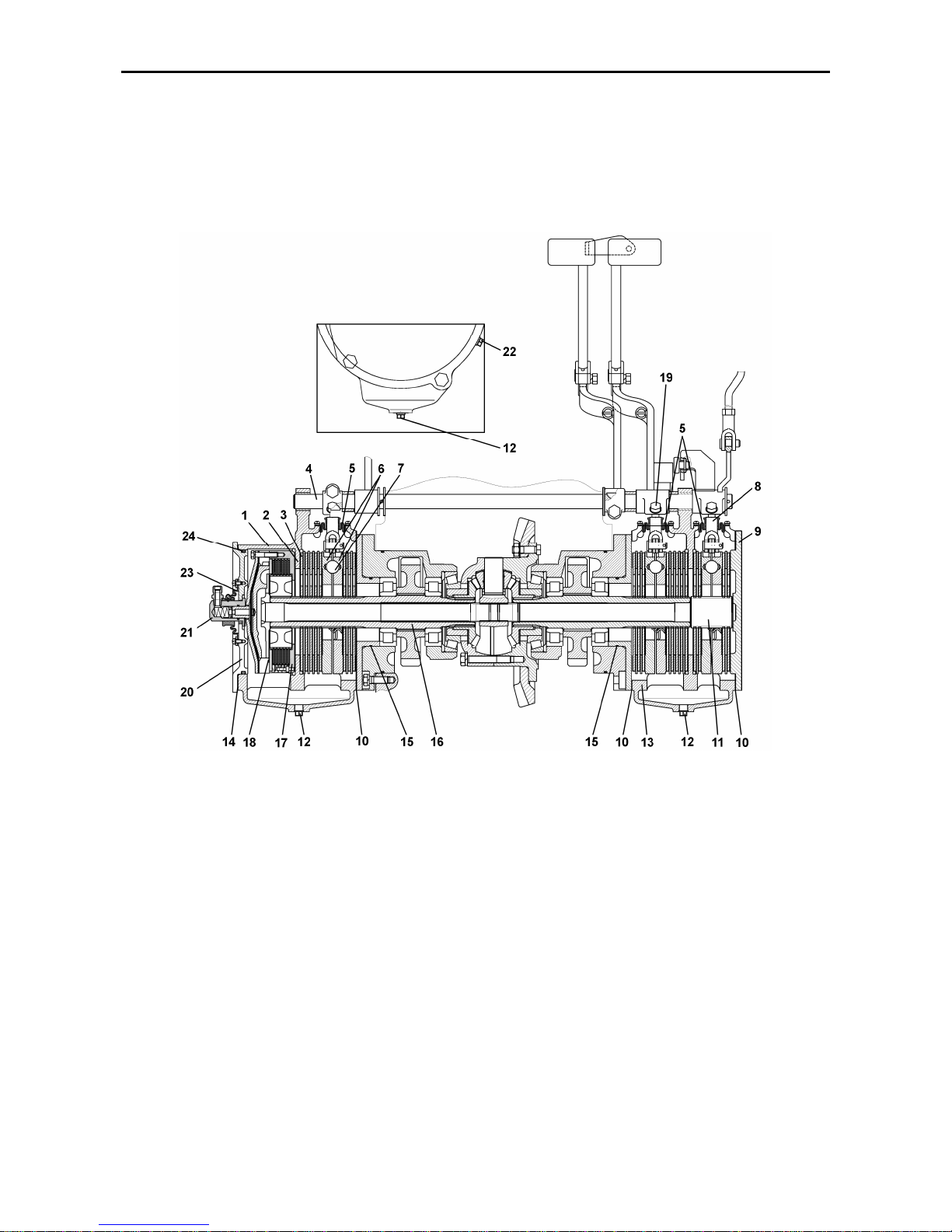
MTZ 1220.1/1220.3 Section D. Construction and Operation
D27
“Wet” Brakes and Rear Axle Differential Lock Clutch (Option)
The tractors can be equipped with multiple-disk service and parking brakes operating in an oil bath.
The rear axle differential lock clutch is
mounted in the brake casing and shares
a common oil bath; therefore it also made
as a “wet” one.
The arrangement of the brakes and lock
clutch is shown in Fig. E-21.2.
Fig. D-21.2. “Wet” brakes and differential lock
1 – brake casing; 2 – friction disk; 3 – intermediate disk; 4 – pedal axle; 5 – protective boot; 6 – pressure
disk; 7 – ball; 8 – parking brake; 9 – cover; 10 – gasket; 11 – parking brake shaft; 12 – drain plug; 13 – brake
casing; 14 – gasket; 15 – O-ring; 16 – final drive pinion; 17 – lock clutch; 18 – boss; 19 – adjusting bolt; 20 –
cover; 21 – adapter; 22 – inspection and filler plug; 23 – sealing boot; 24 – O-ring.
Page 76

MTZ 1220.1/1220.3 Section D. Construction and Operation
D28
Service brakes
The service brakes are of 8-disk type.
The friction disks (2) are installed in
splined ends of the hub drive pinions (16).
The pressure disks (6) are similar in design to those used in dry brakes, but with
a reduced angle of gradient for balls, to
ensure the required force of compression
of the packs of the friction and intermediate packs.
Attention! The pressure disks of dry and
“wet” brakes have the same physical and
fixing dimensions, but they are not interchangeable. It is strictly prohibited to install the disks designated for dry brakes
on “wet” brakes or vice versa. Otherwise,
the safety of tractor operation could be
substantially jeopardized.
The intermediate disks (3) are fixed from
turning in their cases (1, 13) by means of
shoulders made over the outer profile.
The leak-proofness of the oil baths is ensured by the O-rings (15, 24), gaskets
(10, 14) and rubber boots (5, 23). The
cases are provided with inspection (22)
and drain (12) plugs.
Parking Brake
A 4-disk parking “wet” brake (8) is installed in the same case as the multiple
disks service brake. Its components are
unified with those of the service brake.
Differential Lock “Wet” Clutch
The lock-up clutch (17) comprises six
disks with brake ceramic-metal linings fitted on the splined boss (18) connected
with the hub drive pinion (16). A pack of
six friction and five intermediate disks is
compressed as oil under pressure is fed
to the diaphragm space. The frictional
torque developed thereby ensures interlocking of the rear axle differential. The
clutch is made in a single case with the
service brake. It shares a common oil
bath with the brake and is sealed by
means of the cover (20) and special corrugated boot (23) slipped over the adaptor (21) which delivers oil to the head
space of the diaphragm.
Brake Actuators
The service and parking brake actuators
are of mechanical type and consist of the
leverage and pedals.
The actuators of service and parking
brakes of “wet” type are fundamentally
the same as those used in dry brakes on
a respective tractor model.
Page 77
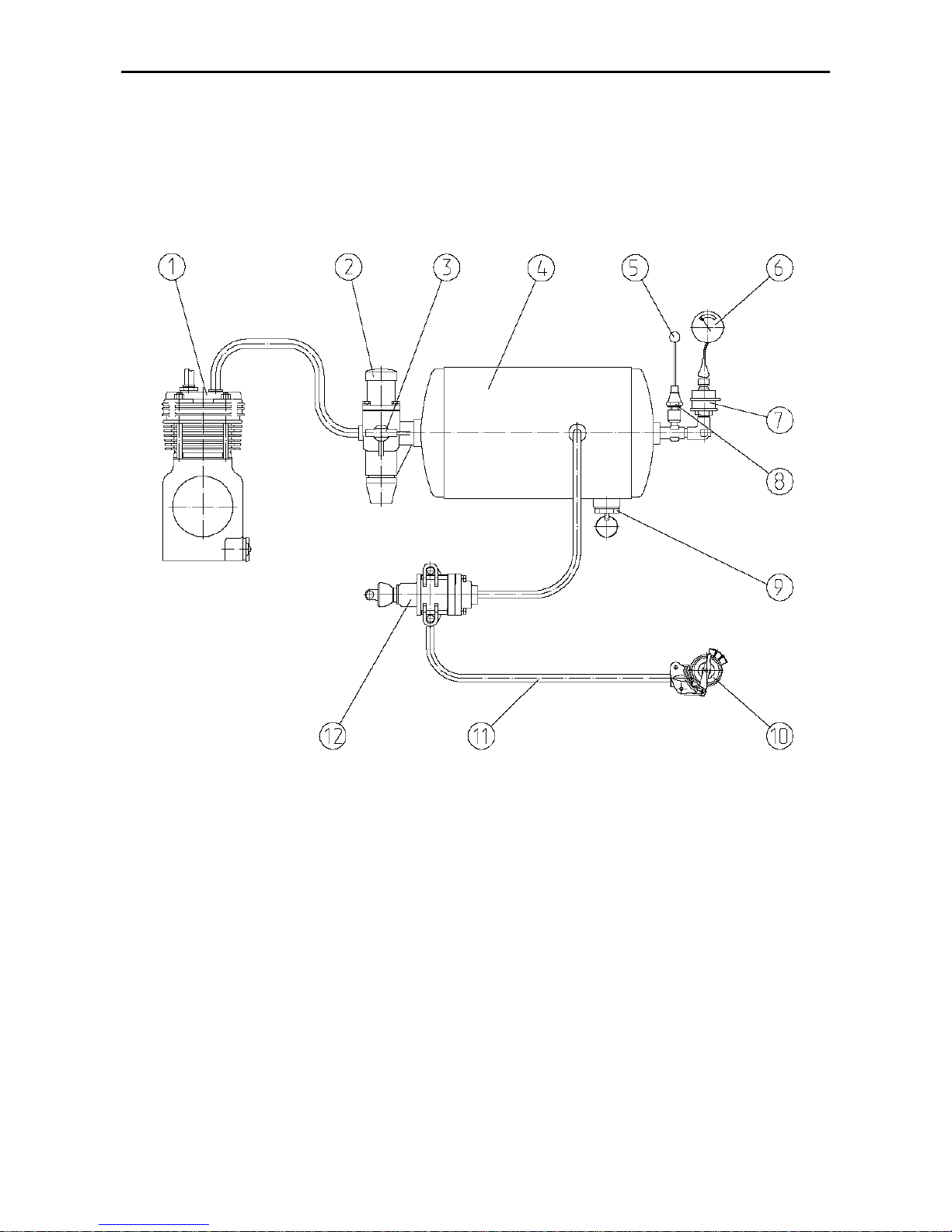
MTZ 1220.1/1220.3 Section D. Construction and Operation
D29
Pneumatic equipment
Single-line pneumatic drive of trailer brakes
The tractors can be equipped with the single-line and double-line pneumatic drive of
the trailers brakes, fitted up with the brakes pneumatic drive.
The pneumatic drive is used for tyre and other goals, where the energy of com-
pressed air is required.
Fig. D-21.4. Double-line pneumatic actuator of the trailer brakes
1 – compressor; 2 – pressure regulator; 3 – air bleeder valve; 4 – air bottle; 5 – emergence pressure indicator light; 6 – pressure indicator; 7 – pressure sensor; 8 – emergence pressure sensor; 9 – condensate drain
cock; 10– coupling heads; 11 – control duct; 12 – brake valve.
Air intake into the pneumatic drive
is made through the engine inlet duct. Air
is compressed in the compressor (1) and,
then, fed to the air bottle (4) via a pressure regulator (2). The latter helps to
maintain the required pressure in the bottle. Compressed air is supplied from the
air bottle to the brake valve (13) and into
the feed duct (12) with a coupling head (a
red lid) which is permanently under pressure. The brake valve (13) is connected
with the coupling head (10a) (with yellow
lid) through the control duct (11). There is
no pressure in this head.
The trailers’ and farm machinery
brakes are controlled in two modes: direct
and automatic.
In case of use of the trailer with
double-line pneumatic actuator, the coupling heads of the trailer are connected to
those (10) (with a red lid) and (10) (with
a yellow lid), i.e. to the feed duct (12) and
to the control duct (11). Here compressed
air is fed continuously to the trailer
Page 78
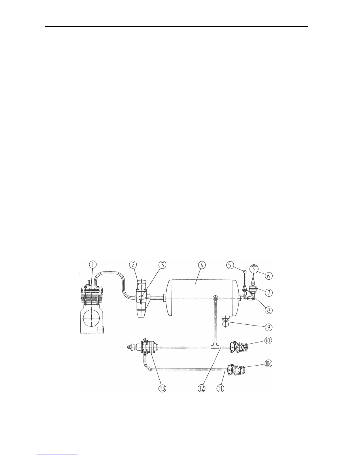
MTZ 1220.1/1220.3 Section D. Construction and Operation
D30
through the fed duct (12). On stepping the
brake pedals or applying the parking
brake, compressed air is delivered to the
trailer through the brake valve (13) and
control duct (11). The air distributor on
the trailer operates to feed the compressed air from the trailer bottle into the
brake chambers that causes the braking
of the trailer.
The direct brake control is
achieved through the pressure increase
in the control duct (11) up to 6.5…8.0
kgf/cm2 when braking the tractor. As this
takes place, the feed duct (12) remains
under pressure, and compressed air supply to the trailer’s pneumatic system is
still retained.
The automatic brake control
(automatic braking) is effected due to a
pressure drop in the trailer feed duct in
case of rupture of the coupling and detachment of the trailer.
The coupling ducts are fitted with
coupling valve-type heads (10) at their
ends. The valve of the coupling heads
prevents the exit of air when the pneu-
matic drive is used with no trailer attached (for example, when inflating tyres)
and in case of emergence detachment of
the trailer. On coupling the duct of the
tractor with that of the trailer, the coupling
head valve opens to ensure the passage
of compressed air from the tractor’s
pneumatic drive to the trailer. The connecting ducts should be couple together
at zero pressure in the tractor air bottle
(4).
The air pressure in the bottle (4) is
monitored by the air pressure indicator (6)
and red indicator lamp of air emergency
pressure (5) (installed in the dashboard),
air pressure sensors (7) and air emergence pressure sensor (8).
The air bottle (4) is provided with
the cock (9) for draining condensate. To
drain condensate move the pusher ring
aside and upwards.
The air intake from the pneumatic
actuator (for inflating the tyres, etc.) is
performed through the air bleeder valve
(3) of the pressure regulator (2).
Double-Line Pneumatic Actuator of the Trailer Brakes
Fig.D-21.4. Double-line pneumatic actuator of the trailer brakes
1 – compressor; 2 – pressure regulator; 3 – air bleeder valve; 4 – air bottle; 5 – emergence pressure indicator light; 6 – pressure indicator; 7 – pressure sensor; 8 – emergence pressure sensor; 9 – condensate drain
cock; 10, 10a – coupling heads; 11 – control duct; 12 – feed duct; 13 – brake valve.
Page 79

MTZ 1220.1/1220.3 Section D. Construction and Operation
D31
.
Air intake into the pneumatic drive
is made through the engine inlet duct. Air
is compressed in the compressor (1) and,
then, fed to the air bottle (4) via a pressure
regulator (2). The latter helps to maintain
the required pressure in the bottle. Compressed air is supplied from the air bottle
to the brake valve (13) and into the feed
duct (12) with a coupling head (a red lid)
which is permanently under pressure. The
brake valve (13) is connected with the
coupling head (10a) (with yellow lid)
through the control duct (11). There is no
pressure in this head.
The trailers’ and farm machinery
brakes are controlled in two modes: direct
and automatic.
In case of use of the trailer with
double-line pneumatic actuator, the coupling heads of the trailer are connected to
those (10) (with a red lid) and (10) (with a
yellow lid), i.e. to the feed duct (12) and to
the control duct (11). Here compressed air
is fed continuously to the trailer through
the fed duct (12). On stepping the brake
pedals or applying the parking brake,
compressed air is delivered to the trailer
through the brake valve (13) and control
duct (11). The air distributor on the trailer
operates to feed the compressed air from
the trailer bottle into the brake chambers
that causes the braking of the trailer.
The direct brake control is
achieved through the pressure increase in
the control duct (11) up to 6.5…8.0
kgf/cm2 when braking the tractor. As this
takes place, the feed duct (12) remains
under pressure, and compressed air supply to the trailer’s pneumatic system is still
retained.
The automatic brake control
(automatic braking) is effected due to a
pressure drop in the trailer feed duct in
case of rupture of the coupling and detachment of the trailer.
The coupling ducts are fitted with
coupling valve-type heads (10) at their
ends. The valve of the coupling heads
prevents the exit of air when the pneu-
matic drive is used with no trailer attached
(for example, when inflating tyres) and in
case of emergence detachment of the
trailer. On coupling the duct of the tractor
with that of the trailer, the coupling head
valve opens to ensure the passage of
compressed air from the tractor’s pneumatic drive to the trailer. The connecting
ducts should be couple together at zero
pressure in the tractor air bottle (4).
The air pressure in the bottle (4) is
monitored by the air pressure indicator (6)
and red indicator lamp of air emergency
pressure (5) (installed in the dashboard),
air pressure sensors (7) and air emergence pressure sensor (8).
The air bottle (4) is provided with
the cock (9) for draining condensate. To
drain condensate move the pusher ring
aside and upwards.
The air intake from the pneumatic
actuator (for inflating the tyres, etc.) is performed through the air bleeder valve (3) of
the pressure regulator (2).
Page 80

MTZ 1220.1/1220.3 Section D. Construction and Operation
D32
Rear PTO
The rear PTO is provided with the twospeed independent (540 and 1,000 rpm)
and synchronous (4.18 revolutions per
metre en route) drives.
The independent drive is provided from
the bearing disk of the clutch via a twospeed PTO drive reduction gear, inner GB
shaft (18) (Fig. E-14), drive shifting clutch
(27) (Fig. E-22) onto the crown gear shaft
(26) of the PTO epicyclical reduction gear.
The synchronous drive is provided via
the shift clutch (27) which couples the epicyclical reduction gear shaft (26) with GB
pinion.
The epicyclical PTO reduction gear is located in the rear axle housing and consists of the crown gear (22) coupled with
shaft (26), three satellites (23) on axles
(21), cage (25) and sun gear (24).
The sun gear (24) is connected with the
engagement drum (17) through a spline
joint. The drum is connected to shaft (20)
and forms, together with the brake band
(16), an engagement band brake.
The cage (25) is made integral with the
brake drum (19) connected with the shaft
(2) and forms, together with the brake
band (18), an engagement band brake.
The inner bore of the shaft (20) houses
replacement PTO end-pieces (10) – 8
spline (540 rpm) or 21 spline (1000 rpm).
The roller (3) of movable ends of the
brake band has an eccentric with lever (5)
to effect adjustment of the clearance in the
band brakes from outside, by simple rotation of the roller (3).
The rear axle casing houses two adjusting
screws (11). These are connected to the
control roller (6) and levers (4), (5).
The PTO is engaged when the brake
band (16) is tensioned and the brake band
(18) is released. In this case, the engagement drum (17) and the sun gear
(24) connected thereto are brought to rest.
Rotational motion is transferred from the
crown gear (22) to the cage (25) and PTO
shaft (20) through satellites (23) running
about the stopped sun gear (24).
The PTO is disengaged when the brake
band (18) is tensioned and the brake band
(16) is released. In this case the PTO replacement end-piece is brought to standstill (10).
Page 81
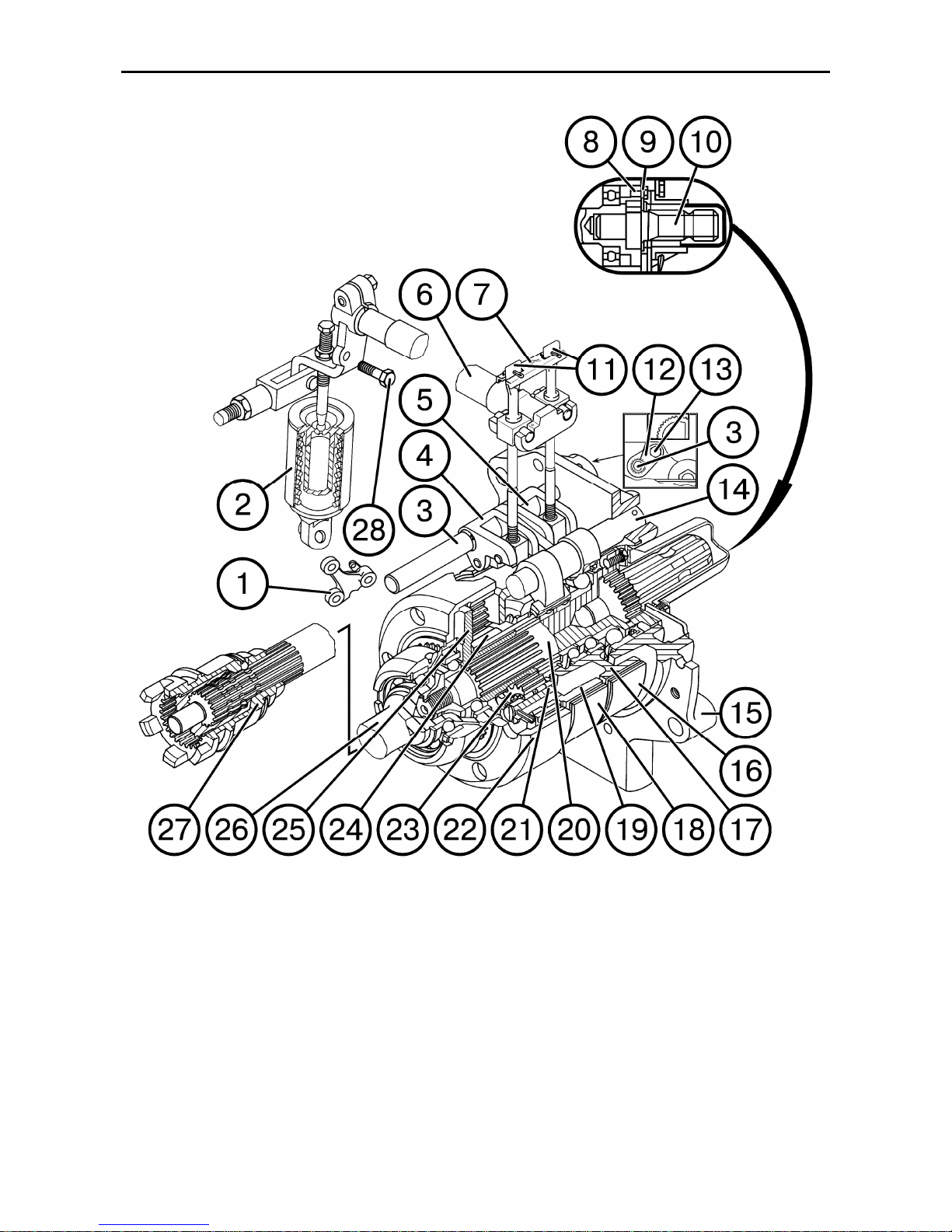
MTZ 1220.1/1220.3 Section D. Construction and Operation
D33
Pic. D-22. Rear PTO epicyclical reduction gear:
1 – bracket; 2 – hydraulic cylinder; 3 – eccentric axle; 4, 5 – lever; 6 – control roller; 7 – stop plate; 8 – endpiece fixing bolt; 9 – replacement end-piece stop plate; 10 – replacement end-piece; 11 – adjusting screws;
12 – stop plate; 13 – stop plate fixing bolt; 14 – axle; 15 – rear cover; 16, 18 – brake bands; 19 – brake drum;
20 – PTO shaft; 21 – satellite axle; 22 – crown gear; 23 – satellite; 24 – sun gear; 25 – cage; 26 – crown
gear shaft; 27 – drive independent/synchronous shift clutch
Page 82
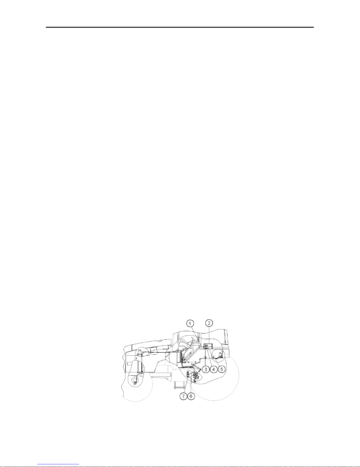
MTZ 1220.1/1220.3 Section D. Construction and Operation
D34
Front PTO control mechanism
The front PTO is controlled by means of the
electro-hydraulic system.
The electric part of the front PTO control system is incorporated in the integrated
system for controlling the real axle DL (differential lock), FDA (front driving axle) drive and
front PTO. It consists of the switch (3),
pushbutton (4), pilot lamp (5) and relay, which
are arranged in the control panel (2) (fig. E-23)
located in the cab to the right from the operator
and interconnected by means of the cab bundle (1) (that of the integrated system for controlling the DL, FDA and front PTO) according
to the attached electric diagram. This bundle
is connected with the transmission bundle (6)
(that of the integrated system for controlling
the DL, FDA and front PTO), which is connected, in turn, to the electro-hydraulic distributor (7) for switching on the front PTO
drive.
The system if supplied with power
from the on-board power system according to
the attached electric circuit diagram. The supply voltage is applied to the system after starting the engine.
The electro-hydraulic distributor (7)
controls the oil flow delivered to the hydraulic
cylinder of the control mechanism of the
band brakes of the front PTO epicyclical reduction gear. The switch (3) has two fixed
positions:
- Engagement of the front PTO drive (press
the smooth portion of the switch);
- Disengagement of the front PTO (press the
corrugated portion of the switch).
To engage the drive of the front PTO,
it is necessary to set the switch (3) to the position “Engagement of the front PTO drive”
with the engine running and then press the
pushbutton (4) for starting the front PTO and
release the same. When doing this, the contacts of the relay in the control panel (2) get
closed and the electromagnet of the electrohydraulic distributor (7) is energized, the slide
of the electro-hydraulic distributor (7) moves
and oil is delivered to the rod-free cavity of
the hydraulic cylinder for controlling the front
PTO, and the rod cavity is connected with the
drain.
The engagement of the front PTO
drive is signaled by means of the pilot lamp
(5) (fig. E-23).
To disengage the front PTO, it is nec-
essary to set the switch (3) to the position
“Disengagement of the front PTO (press the
corrugated portion of the switch). When doing
this, the contacts of the relay in the control
panel (2) get open, the electromagnet of the
electro-hydraulic distributor (7) is deenergized, the slide returns to the initial position, the rod-free cavity of the hydraulic cylinder is connected with the drain, oil is delivered to the rod cavity, the front PTO drive is
disengaged and the pilot lamp (5) goes out.
When stopping the engine, the front
PTO is disengaged automatically. Therefore,
to engage the front PTO drive after the next
starting of the engine, it is necessary to press
the pushbutton (4) (repeat the operations for
engaging the PTO).
Fig. D-23. Front PTO control mechanism.
1 – bundle; 2 – control panel; 3 – switch; 4 – pushbutton; 5 – pilot lamp; 6 – bundle; 7 – electro-hydraulic distributor
Page 83
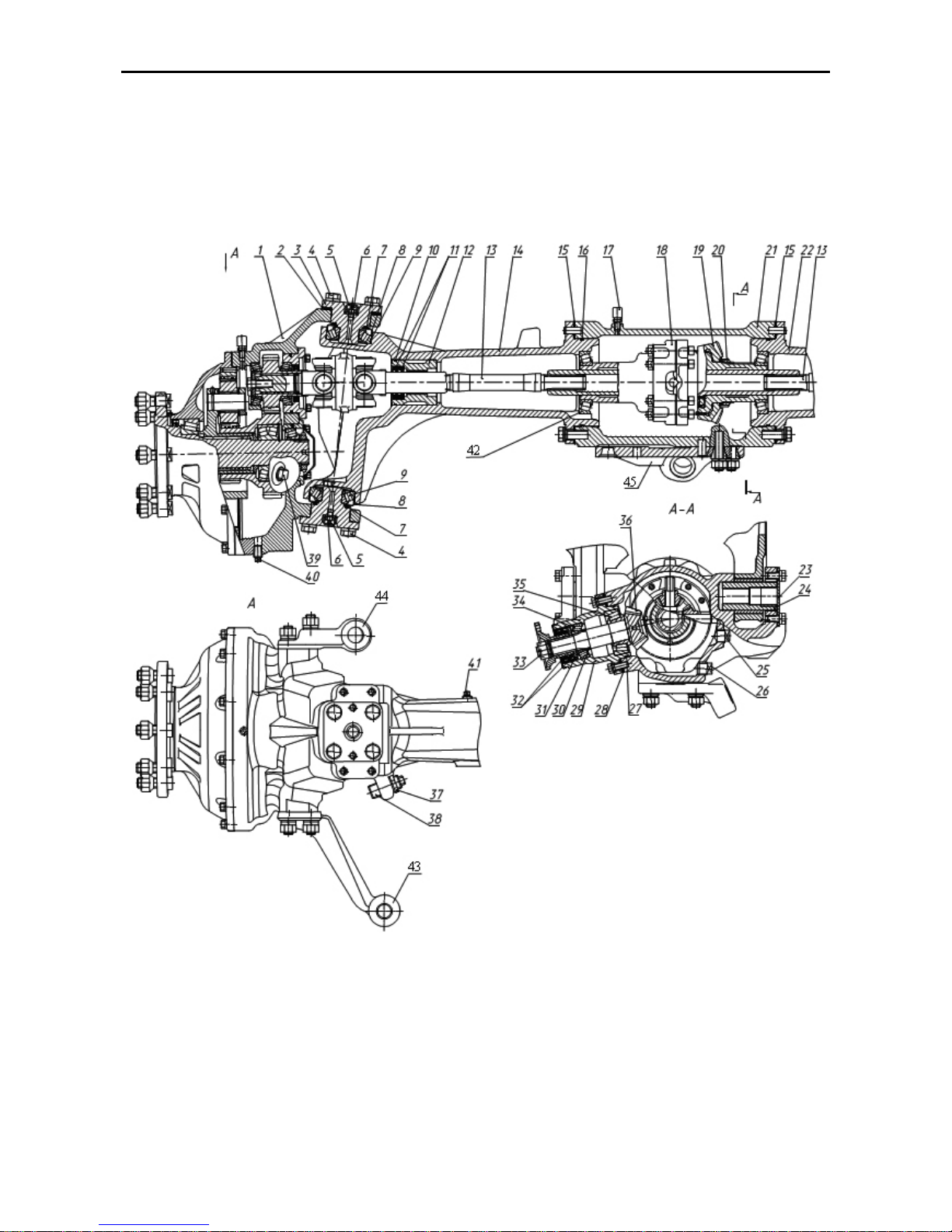
MTZ 1220.1/1220.3 Section D. Construction and Operation
D35
Front driving axle
The front driving axle (FDA) is intended for transmitting the torque from the engine to
the front steerable wheels of the tractor. It consists of the final drive, differential and wheel
reduction gears.
Its final drive is a pair of conical gears with the helical tooth. The design of FDA with twospeed planetary cylindrical reducing gears of final drives is given on Fig. Д-24.
1 – driven bevel gear; 2, 15, 28 – adjusting shims; 3 – steering knuckle pivot spindle; 4 – bolt; 5 – cap; 6 –
lubricator; 7, 10, 16, 27 – rubber ring; 8 – sleeve; 9, 34, 35 – taper roller bearing; 11, 32 – collar; 12 – fixture;
13 – half-axle shaft; 14 – left-hand housing; 17 – breather; 18 – differential; 19 – driven bevel gear; 20 – nut;
21 – FDA casing; 22 – right-hand housing; 23 – washer; 24 – pivot; 25 – plug; 26 – draining plug; 29 – driving gear carriage; 30 – adjusting washers; 31 – wiper ring; 33 – nut; 36 – driving bevel gear; 37 – locknut; 38
– screw; 39 – filling plug; 40 – draining plug, 41 – filling plug, 42 – lubricator.
Fig. D24 – FDA with two-stage planetary-cylindrical reduction of final gear
Page 84

MTZ 1220.1/1220.3 Section D. Construction and Operation
D36
The driving gear (36) of the final drive is mounted in the carriage (29) on two taper roller
bearings. The tightness in the bearings is adjusted by means of adjusting washers (30), after which
they are tightened by means of the nut (33). The driven gear (19) is fitted on the splines and centring spigot of the differential casing (18) and locked against axial displacement by means of the
nut (20).
The final drive mesh is adjusted by means of the adjusting shims (28), (15) placed between
the flange of the driving gear carriage and FDA casing as well as between the left- and right-hand
housings and FDA casing, respectively. Before adjusting the mesh, the differential bearings shall
be adjusted by means of the shims (15).
The left-hand (14) and right-hand (22) housings connected with the FDA casing (21) by means
of bolts form the front axle beam. The FDA casing is provided with a breather (17) maintaining the
normal pressure in the cavity of the axle and final drive beam.
The axle beam is filled with oil to the lower edge of the filling opening through the plugs (41) installed in the housings (14) and (22). To drain oil from the axle beam, screw out the draining plug
(26) located in the FDA casing. Oil shall be fed through the opening in one of housings until the
lubricant in another housing reach the lower edge of the filling opening. The FDA shall be filled with
oil on a horizontal surface.
The FDA casing (21) is connected with the beam by means of the pivot (24), on which the
axle with the wheels can swing in the cross plane while deflecting to the angles limited by the stops
of the ribs in the housings (14) and (22) when they contact the tractor beam. The pivot is locked
against axial displacement by means of the washer (23). The pivot is greased through the lubricator (42).
The opening for the plug (25) serves for checking the adjustment of the final drive mesh.
Oil leakage from the cavity of the final drive and axle beam is prevented by using the collars
and rubber rings placed in the fixtures, housings and driving gear carrier.
To prevent the oil upthrust upstream the collar of the driving gear, the latter’s splined end is
fitted with the wiper ring (31) with spiral groves cut over the outer diameter of the ring. A slide bearing with crossed grooves is mounted in the fixture (12).
The housing (21) of the front driving axle is connected with the beam by two hollow axes
(24), on which the axle with the wheels can swing in the diametral plane being deviated by angles
limited by rib stop in the arms (14) and (22) in case of their contact with tractor beam. Axes are limited against axial displacement by plates.
Differential
The differential is self-locking, with increased friction. The casing (1) and cover (7) of the
differential bolted together contain the two pairs of satellites (6) on floating pins (5), axle-shaft
gears (8), pressure cups (4) as well as driving (2) and driven (3) friction disks.
The self-locking differential connects automatically both the axle shafts and excludes separate
skidding of the wheels that increases the tractive force of the front wheels. The locking takes place
when the front axle is engaged. At that moment, the satellite shafts turn under load and move over
the bevel slots in the casing and cover of the differential, respectively, by the value of the clearances between the friction disks. From the pins, the force is transmitted to the satellites which, in
turn, transmit it through their beads to the cups, and the latter press the friction disks against one
another until they rest against the walls of the casing and cover of the differential. The driving
plates having the outer teeth are in mesh with the teeth of the casing and cover of the differential
and the driven plates (through their inner teeth) – with the axle shaft gears. The friction force of the
pressed together disks unites the axle-shaft gears and casing with the cover of the differential into
a whole while locking in such a way the differential.
When the front axle is engaged and the external forces exceed the friction forces in the friction
disks during the turning of the tractor, the friction disks will skid.
The differential is installed in the two taper roller bearings in the housings of the front axle
beam. The bearings of the differential are adjusted by means of the shims 15 (see Figure “FDA”).
Page 85
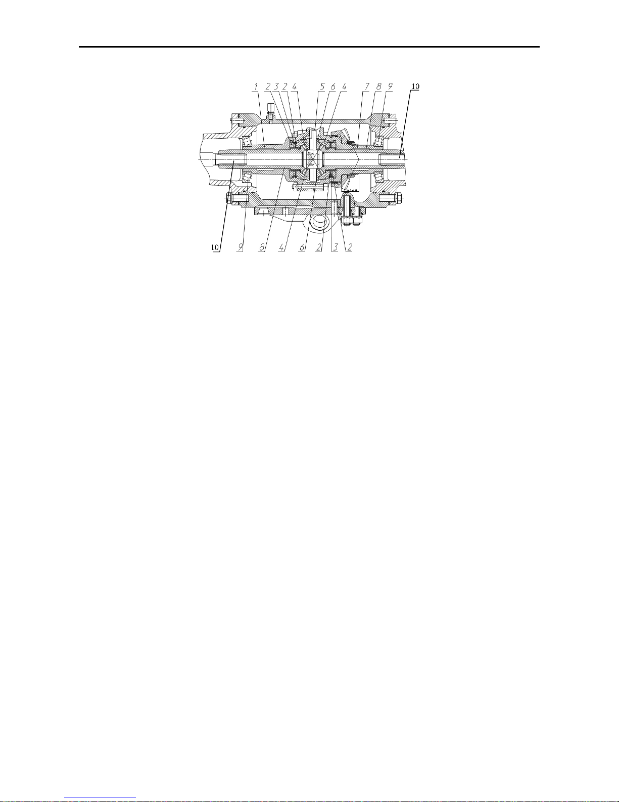
MTZ 1220.1/1220.3 Section D. Construction and Operation
D37
1 – differential casing; 2 – driving plate; 3 – driven plate; 4 – pressure cup; 5 – satellite shaft; 6 – satellite; 7 –
differential cover; 8 – axle-shaft gear; 9 - taper roller bearing.
10 – semi-axis shaft.
Fig.D-25.
Differential
Wheel reduction gears of planetary spur-gear type
Wheel reduction gears of planetary spur-gear type are intended for transmitting and increasing the
torque from the FDA differential at various angles of turning of the front steerable driving wheels.
The reduction gears are mounted in the casings (35) and connected with the axle beam by
means of spindles (3) (see Figure “FDA”) and can turn relatively to the FDA beam on the two bearings (9). The spindles are connected with the wheel reduction gear casing by means of the bolts
(4). The screw (38) and locknut (37) serve for adjusting the angle of turn of the wheel reduction
gears.
The pivots (3) are lubricated through lubricators (6) mounted on the pivots. The lubricators are
protected against penetration of dirt by means of rubber caps (5). To protect the pivot bearings
from dirt, the sleeves (8) with sealing rubber rings (7) are installed in the housings of the axle
beam. The pivot bearings (9) are adjusted by means of the shims (2) located under upper spindles
(3).
The wheel reduction gear (1) consists of a doubled joint, spur-gear and planetary drives, levers
for controlling the turning of the front wheels.
The doubled universal joint (24) (see Figure “Wheel reduction gears”) is connected with the
FDA differential by means of half-axle shaft with splined ends (13) (see Figure “FDA”) from the one
side and with the driving gear (17) from the other side (see Figure “Wheel reduction gears”) of the
spur-gear drive.
The driving gear is mounted on the two taper roller bearings (18). One of them is installed in the
counterbore of the reduction gear casing (35) and another – in the carrier (22). The doubled universal joint is fixed in the pinion by means of the washer (15) and bolt (14) with a bent-out plate.
The bearings (18) are adjusted by means of the shims (21) which are placed between the carrier and the reduction gear casing.
The driving gear of the wheel reduction gear is in mesh with the rear block (driven gear of the
spur-gear drive) (34) the second crown of which is a sun gear or driving part of the planetary series. The driven part of the planetary series connected with the tractor wheel is the wheel flange
which is spline-connected rigidly with the cage (5) by means of three satellites (11), while the epicyclic gear (12) serves as a braked gear perceiving the reactionary torque.
The epicyclic gear is mounted in the reduction gear and fixed against turning by three pins (13).
An additional gasket is placed between the cover and casing of the reduction gear. The sun gear is
mounted on the wheel flange, on the two-row taper bearing (33) which is fixed from the one side by
Page 86
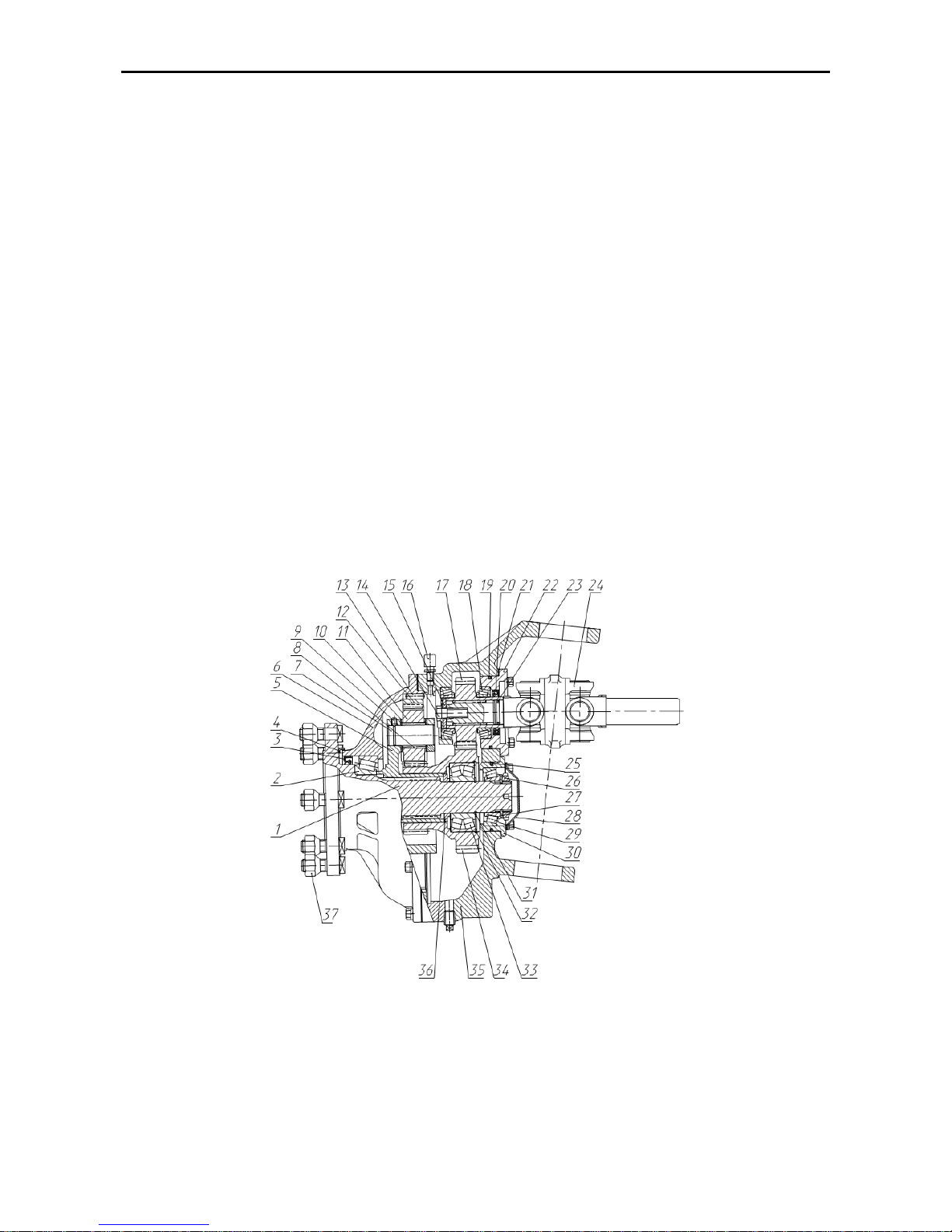
MTZ 1220.1/1220.3 Section D. Construction and Operation
D38
means of the thrust ring (36) being in contact with the cage and from the other side – by means of
two locking rings (31, 32).
The satellites rotate on the shafts (7) mounted in the counterbores of the cage (5). The cylindrical rollers (8) serve as satellite bearings. One race of the rollers is the ground surface of the shaft
(7) and another is the ground internal surface of the satellite (11).
The satellites and rollers are kept from displacement in the axial direction by the washers (10).
The force fit in the connection of the cage with the shaft is used for keeping the satellite shafts from
the axial displacement. The screw (9) turned into the grove of the shafts serves for checking the
correctness of the press-fitting and additional fixation.
The wheel flange is mounted in the two roller bearings. One of them is mounted in the reduction
gear cover (6) and the other – in the carrier (30) which is installed in the counterbore of the reduction gear casing, closed by means of the cover (28) and fastened to it by means of the bolts. An
additional gasket is inserted between the carrier and the cover.
The bearings are adjusted by tightening the nut (26). The washer (27) is placed between the
bearing (29) and the nut (26). To prevent the nut from turning out, the nut shoulder is punched in
the slot of the wheel flange.
The reduction gear casing shall be filled with oil to the lower edge of the filling hole, into which
the plug (39) is inserted (see Figure “FDA”). To drain oil, unscrew the draining plug (40).
The internal cavity of the wheel reduction gear is sealed by means of the collars (3) (see Figure
“Wheel reduction gears”) and (20). The mud trap (4) is installed for preventing the penetration of
mud to the working edges of the collar (3). The counterbores of the steering knuckle and splines of
the doubled universal joint shall be sealed by means of rubber rings (19, 23, 25). For maintaining
the normal pressure in the reduction gear cavities, the reduction gear casing is provided with a
breather (16).
1 – wheel flange; 2, 18, 29 – taper roller bearing; 3, 20 – collars; 4 – mud trap; 5 – cage, 6 – reduction gear
cover; 7 – satellite shaft; 8 – rollers; 9 – screw; 10 – thrust washer; 11 – satellite; 12 – epicyclic gear; 13 –
pin; 14 – bolt; 15 – washer; 16 – breather; 17 – driving pinion; 19, 23, 25 – rubber ring; 21 – adjusting shims;
22 – driving pinion carrier; 24 – doubled universal joint; 26 – nut; 27 – washer; 28 – cover; 30 – carrier; 31,
32 – locking ring; 33 – two-row taper roller bearing; 34 – gear block; 35 – reduction gear casing; 36 – ring; 37
– wheel nut.
Fig.D-26.
Wheel reduction gears of planetary spur-gear type
Page 87
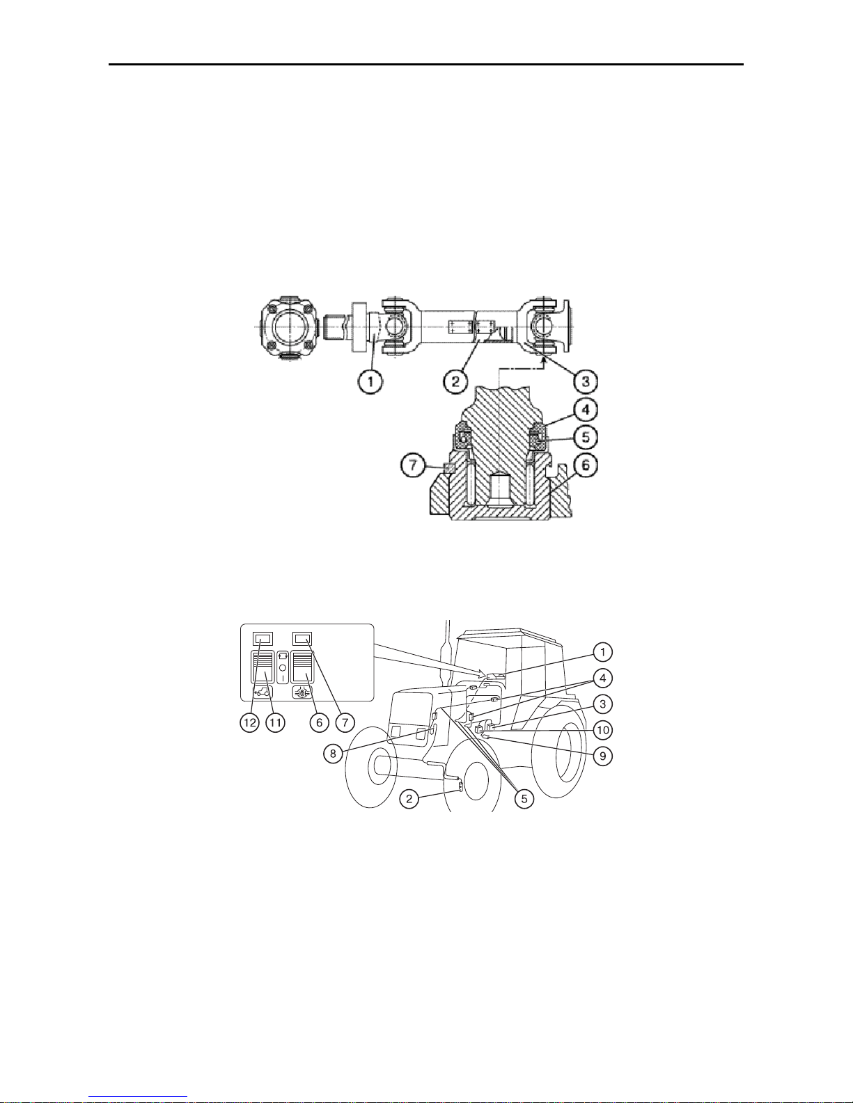
MTZ 1220.1/1220.3 Section D. Construction and Operation
D39
Cardan shaft
The cardan shaft is intended for transmitting the torque from the GB to the FDA.
The cardan shaft consists of a tube (2)
and two hinges (1), (3) (Fig. Д-27) with the
cross bar running in needle bearings (6).
The needle bearing cages are locked with
retaining rings (7); the cross bars trunnions are provided with edge-joint packings (4) and self-tightening collars (5).
The cardan shaft in assembly is dynamically balanced.
To ensure against winding of strawstemmed crops on the cardan shaft when
harvesting, a special enclosure is provided.
Fig. D-27. Cardan shaft
:
1, 3 — cardan hinges; 2 — cardan shaft tube; 4 —
edge-joint packing
; 5 — collar; 6 — needle
bearing; 7 — lock ring
Electro-hydraulic control of FDA drive
Fig.D-28. Rear axle differential lock-up (DL) and FDA drive control system:
1 – control panel; 2 – steering wheels turning angle sensor; 3, 10 – control electro-hydraulic distributors for
the DL and the FDA drive, respectively; 4 – terminal blocks; 5 – connecting cable; 6 – DL control key; 7, 12 –
indicator lamps; 8 – loop; 9 – automatic FDA drive control sensor; 11 – FDA drive control key.
The electro-hydraulic control system of
the rear axle (Fig. E-28) consists of the
panel (1), automatic control sensor (9)
FDA reduction gear, FDA drive clutch
control electro-hydraulic distributor (10)
located on the right-hand GB cover and
connecting cables (5) with terminal blocks
(4). The system is supplied with power
from the on-board power system via a
safety fuse in the fuse box installed in the
dashboard. The system is powered after
starting the engine. The key (11) of the
FDA drive control and the FDA drive engagement indicator lamp (12) are in-
Page 88

MTZ 1220.1/1220.3 Section D. Construction and Operation
D40
stalled on the panel (1) face. The latter is
located over the tractor right-hand side
control panel.
Note: A braking relay is provided in the
FDA drive control electric circuit. It ensures the automatic engagement of the
drive when stepping on the interlocked
service-brake pedals.
How To Use the Front Driving Axle
Control Key (11)
1. When performing jobs with great extent
of slippage of front wheels, press the
upper part of the key (11) having activated the automatic FDA drive control
mode. When it will be done, the automatic control is exercised depending
on tractor slippage, which is sensed by
sensor (9) of automatic control. When
rear wheels are slipping, the sensor (9)
closes contacts and energizes the
electromagnet of the control electrohydraulic distributor (10). When slipping intensity drops, the sensor (9)
beaks contacts to de-energizing the
electromagnet and disengage the FDA
drive, respectively.
2. If the job requires operation with forward and reverse moves, with the FDA
engaged all the way through, depress
the lower part of the key (11). To disengage the FDA drive, press the key
(11) to its middle position.
ATTENTION!
1. When reversing, NEVER engage the automatic FDA drive control mode; use the
forced drive only. Use the forced drive mode of the FDA for short-run jobs only: to
clear an obstacle or when running the tractor in reverse.
2. Be sure to disengage the FDA when on surfaced roads to avoid accelerated wear of
the front wheel tyres, drive parts and FDA.
Hydraulic Lift Linkage (HLL)
The HLL is intended for controlling and
operating the tractor aggregated with
mounted, semi-mounted and pull-type agricultural machines and implements attached to the rear hitch linkage (RHL).
The hydraulic system is composed of controls, an oil tank with filter, oil, pump, twoor three-section flow-through distributor,
hydraulic power lift and power lift drive.
The operating controls of the hydraulic
system (7), (8) (Fig. E-29) are located in
the tractor cab, with the exception of the
pump engagement handle (the design is
left unchanged) and additional position
control handle (8) (Fig. E-29) located on
the rear of the tractor on the hydraulic
power lift.
Control of External Loads – these are
three handles of the flow-through distributor located on the right-hand side of the
steering wheel (the design is left unchanged).
Positions of the handle (from bottom to
top) are: “Lift”, “Neutral”, “Drop” and
“Floating”.
Page 89
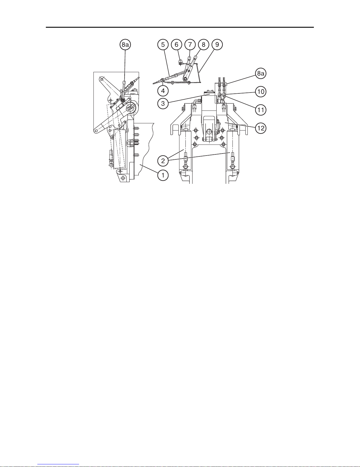
MTZ 1220.1/1220.3 Section D. Construction and Operation
D41
Fig.D-29. Hydraulic power lift of the HLL (monoblock):
1 – rear axle casing; 2 – power ram cylinders; 3 – regulator-distributor; 4 – brackets; 5 – position (10)
and draft (11) lever control ropes; 6 – adjustable RHL travel limiter; 7 – draft control handle; 8 – position control handle; 8a – additional position control handle; 9 – right-hand side control panel; 10 – position lever; 11 –
draft lever; 12 – casing.
The draft control handle (7) (Fig.
E-29) is located on the right-hand control
panel (9), the first from the operator’s
seat. The operational range of the handle
positions is marked with digits from 1 to 9
that corresponds to the entire span of
ploughing depths from minimal to maximal ones, respectively.
The position control handle (8) (Fig. E-
29) is located next to the draft control
handle (7). Its operating range is marked
with the same digits which cover RHL positions from the upper transport position
down to the lowermost position, respectively.
The additional position control handle
(8a) (Fig. E-29) is located on the rear of the
tractor on the hydraulic power lift. Pulling
this handle towards the operator standing
behind the tractor and looking along the
tractor forward travel lifts the RHL and pushing the same from the operator lowers the
RHL.
The RHL travel limiter (6) is located in the
slot of the right-hand side panel, in which
the position control handle (8) moves.
The positions of the oil tank, oil pump filter and the distributor to control external
loads are unchanged. The distributor is of
a sectional flow-through type; it has priority in control over the hydraulic power lift.
Hydraulic Power Lift (Fig. D-29, E-30)
The hydraulic power lift (Fig. E-29) is installed on studs, on the rear wall of the
rear axle casing (1) and consists of a control unit and a regulator-distributor (3) built
in a single casing (monoblock) which
houses two hydraulic single-acting power
cylinders (2).
Page 90
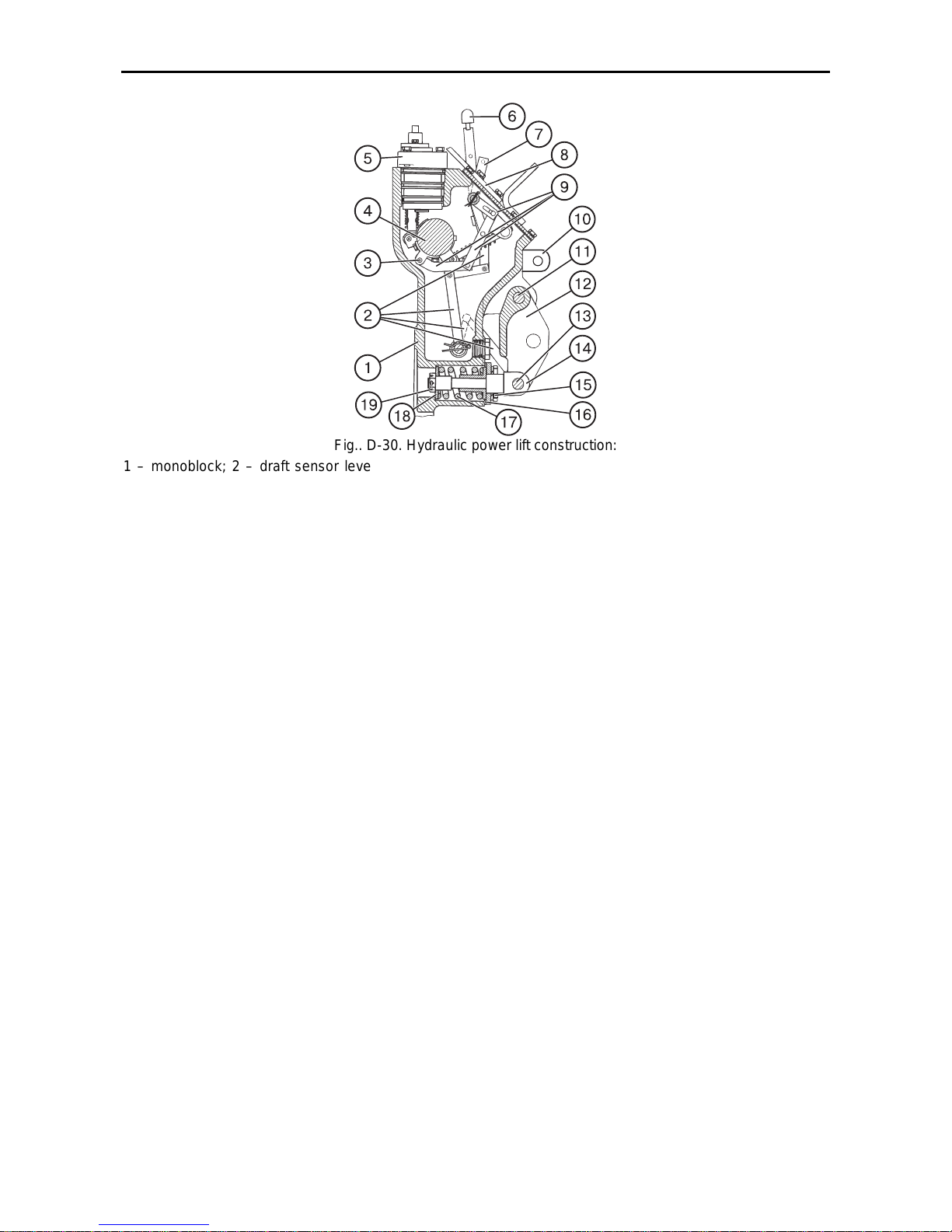
MTZ 1220.1/1220.3 Section D. Construction and Operation
D42
Fig.. D-30. Hydraulic power lift construction:
1 – monoblock; 2 – draft sensor leverage; 3 – position sensor; 4 – RHL lifting levers shaft; 5 – regulatordistributor; 6 – position lever; 7 – draft lever; 8 – lid; 9 – position sensor leverage; 10 – lifting levers; 11 –
shackle axle; 12 – draft sensor coupling link; 13 – pin; 14 – draft sensor rod; 15 – cover; 16 – adjusting shims
for draft sensor spring; 17 – draft sensor spring; 18 – dish; 19 – nut
The control unit is mounted in the monoblock (1) (Fig. D-30) and consists of a
position sensor in the form of a bracket
attached to shaft (4) of the RHL lift levers (10); draft sensor involving the coupling link (12) mounted on axle (11) in
the monoblock (1) and coupled with rod
(14) on pin (13). The spring (17) preloaded by the nut (19) is fitted on the rod
(14). Through a leverage system (9) the
position sensor (3) is connected to position handle (6). The pin (13) of the rod
(14) is coupled with draft handle (7)
through leverage (2).
The control unit operates as follows:
When the position control is used, the
draft handle (7) (Fig. D-30) should be
shifted to its foremost position, in the direction of the tractor forward travel. Further control of the hitch linkage is
achieved by means of the position lever
(6) (Fig. D-30) and handle (7) via ropes
(5) (Fig. D-29). When moving the lever
(6) backward, the hitch linkage is lifted
and then moving the lever (6) forward,
the hitch linkage is lowered. This adjusting process is performed by means of
the regulator-distributor built in the monoblock (1) and controlled be means of
the position sensor (3).
When the draft control is used, the
position handle (6) should be shifted to
its foremost position, in the direction of
the tractor forward travel, corresponding
to the bottom position of hitch drop links.
The draft control handle (7) is set to the
required ploughing depth; further the
process of adjustment is fulfilled by the
built-in regulator-distributor (5) under
control of the draft sensor.
Using the position control handle (8) (8)
(Fig. D-29) for limiting the ploughing
depth when operating in the draft control
mode makes it possible to achieve the
combination adjustment.
The Regulator-Distributor (5) built-in
into the monoblock (1) is an adjusting
element of the hydraulic power lift. It is a
slide-valve gauge whereby the operating
position like “Lift”, “Drop”, “Neutral” and
RHL automatic control can be achieved.
The hydraulic power lift drive (Fig. D-29)
consists of a bracket (4) with the draft
(7) and position (8) handles mounted on
it. The latter are connected to the draft
(11) and position (10) levers, respectively, by means of two-way ropes (5).
The control levers are locked by springloaded friction disks.
Page 91
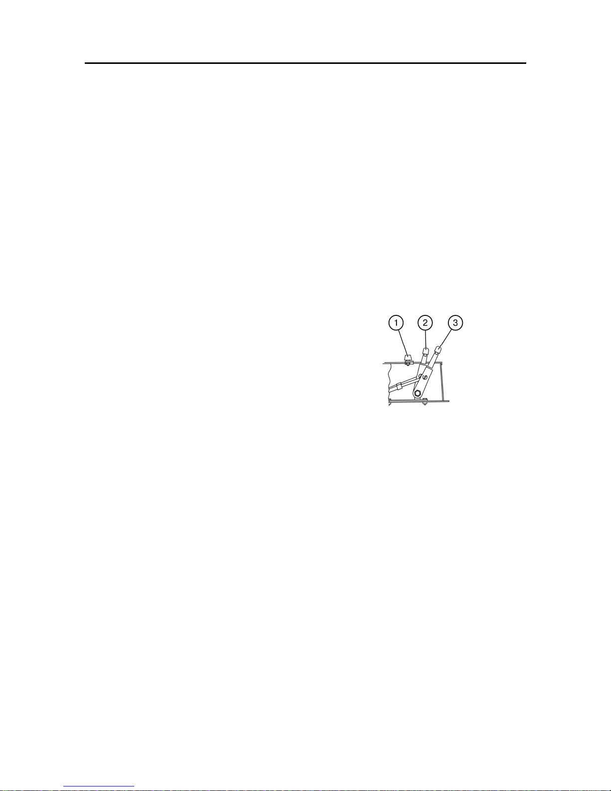
MTZ 1220.1/1220.3 Section D. Construction and Operation
D43
Hydraulic System Operation
The hydraulic system for controlling the
three-point RHL is equipped with the regulator-distributor built in the monoblock. The
regulator-distributor provides the system in
the following modes:
• draft control;
• position control;
• combination control.
The efficient use of these modes depends
on the machines to be ganged and agrotechnical conditions.
Position control
Provides for precise and sensitive control of
the mounted equipment such as sprayer, land
leveller, etc. above the ground. The position
control can be used with land-treatment machines, semi-mounted ploughs with extendible cylinders, etc.
However, this adjustment type is not recommended for use on uneven fields. The
position control on a field with uneven surface can cause shocks caused by quick vertical movements of the coupling arrangement.
Draft control
It is the most suitable mode for operation
with mounted or semi-mounted implements,
the work members of which are deepened
into the soil. The system is sensitive to the
draft variations (caused by the variations of
the soil resistance depending on the depth
of the soil treatment) through the central
connecting rod of the central rod of the hydraulic lift linkage. The hydraulic system respond to these variations by lifting or lowering the implement so that the draft would be
maintained at a constant level. The system
responds to the compression and tension
forces in the central rod, i.e. it is a doubleaction system.
HLL Operation
The HLL is controlled by means of two handles located on the right-hand control panel
in the cab:
• draft control handle (2); and
• position control handle (3).
Position control
1. Set the draft control handle (2) to the
foremost position in the direction of the
tractor travel.
2. Set the necessary height on the implement above the soil by means of the position control handle (3).
The digit “1” on the control panel corresponds to the transport position of the RHL
and the digit “9” – to the minimum height of
the implement above the soil.
If it is necessary to restrict the maximum
lifting height (for example, due to the possibility of breakage of the parts of the rear
axle), set the maximum lifting height by
means of the handle (3) and move the adjustable stop (1) to the latter.
Draft control
Use this method of adjustment when working with the mounted implements (ploughs,
cultivators). Move the draft control handle
(2) to the foremost position in the direction
of the tractor forward travel (digit “9” on the
control panel).
Connect the implement to the RHL by
means of the position control handle (3).
On entering the furrow move the handle (3)
to the foremost position and adjust the desirable soil treatment depth by means of the
handle (2).
On leaving the furrow and subsequent entering the same (when performing the tillage), use the position control handle (3)
without touching the draft control handle (2).
If it is impossible to achieve the constancy
of the soil treatment depth due to unevenness of the soil density, limit the maximum
depth by means of the position control handle (3) (combination control mode) having
memorized the respective digit on the control panel.
Page 92
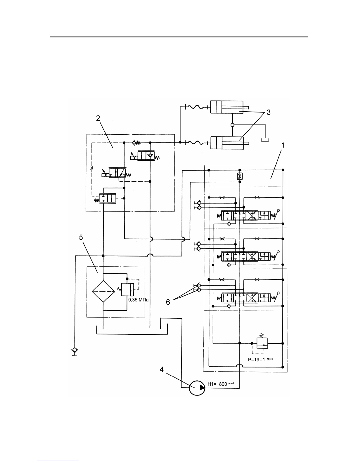
MTZ 1220.1/1220.3 Section D. Construction and Operation
D44
Hydraulic lilt linkage based on the electro-hydraulic regulator of the RHL control
The tractor is equipped with two 90220 vertical hydraulic cylinders built in the lift
(without regulator) controlled from the electro-hydraulic regulator. The schematic hydraulic diagram of he hydraulic system with the electric-hydraulic regulator of the RHL
control in shown in Fig. E-31.
Fig. D-31. Schematic hydraulic diagram
1 – RS 213 “Mita” hydraulic distributor; 2 – R5- electro-hydraulic regulator; 3 – 80220 hydraulic
cylinders; 4 – 32-3 pump; 5 – drain filter; 6 – quick-connection couplings.
Page 93
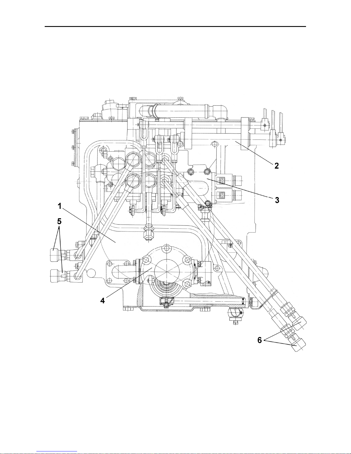
MTZ 1220.1/1220.3 Section D. Construction and Operation
D45
The functions of control of the RHL
and hydroficated working members of
the external consumers are implemented in the new hydraulic system
(Fig. E-32) at the cost of the electro-
hydraulic block (3) mounted on the oil
tank (1). The lever control of the distributor (2) and 32-3 the gear
pump are similar for all the versions of
the above hydraulic systems
.
Fig. D-32. Casing of the hydraulic units assembled with the other ones
1 – oil tank; 2 – distributor control; 3 – electro-hydraulic unit (RS 213 “Mita” + adaptor +
R5); 4 – 32-3 pump; 5, 6 – side leads.
Page 94
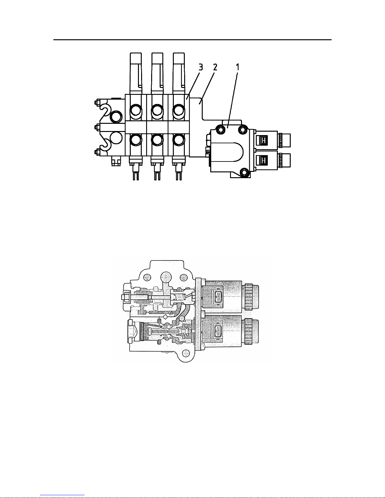
MTZ 1220.1/1220.3 Section D. Construction and Operation
D46
Fig. D-33. Electro-hydraulic unit
1 – R5- electro-hydraulic regula-
tor; 2 – adaptor plate;
The electro-hydraulic unit (Fig. E-33)
consists of distributing sections of the
RS213 “Mita” distributor manufactured in
Finland, R5- electro-hydraulic
regulator manufactured by the Bosch
Company (Germany) and adaptor plate
(2) manufactured by the MTZ.
The construction arrangement of the
R5- electro-hydraulic regulator is
shown in Fig. E-34.
Fig. D-34. R5- electro-hydraulic regulator
The R5- electro-hydraulic regulator (Fig.-34) is controlled by two proportional magnets with th use of the electronic RHL control system (see Fig. D-37)
Page 95
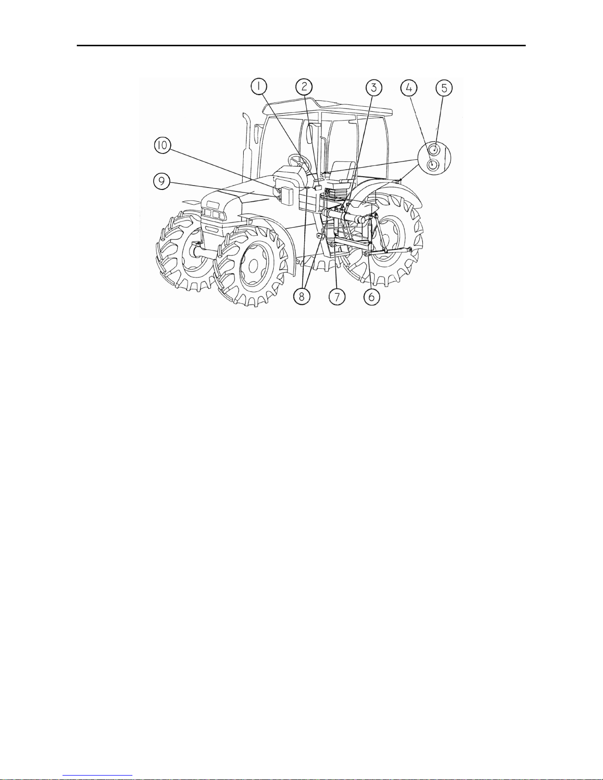
MTZ 1220.1/1220.3 Section D. Construction and Operation
D47
Electronic RHL control system
Fig. D-35. Electronic RHL control system
1 – RHL control panel; 2 – electronic unit; 3 – RHL position sensor; 4 – button for remote
control of lowering the RHL; 5 – button for remote control of lifting the RHL; 6 – left-hand
force sensor; 7 – right-hand force sensor; 8 – connecting cables with electric connectors; 9
– solenoid valve for lowering; 10 – solenoid valve for lifting.
The electronic part of the regulator control includes the following components:
• RHL control panel (1);
• Buttons (4, 5) for remote control of the RHL;
• Electronic unit (2);
• Force sensors (6, 7);
• RHL position sensor (3);
• Solenoid valves for lifting (10) and lowering (9);
• Connecting cables with electric connectors (8).
The electronic part of the system operates as follows. On turning the key switch
of the starter and instrumentation to the
position “Instrumentation energized”, the
power supply voltage is fed from the electric equipment system through an singleterminal block with violet wire (on the right
side under the dashboard) to the electronic unit 2 of the system. The electronic
unit polls the sensors and system control
components and, after analysis, gives
necessary commands to the regulator solenoids. The system is controlled either
from the control panel 1 located in the
tractor cab or by means of the remote
control buttons 4 and 5 located on the
fenders of the rear wheels.
Page 96
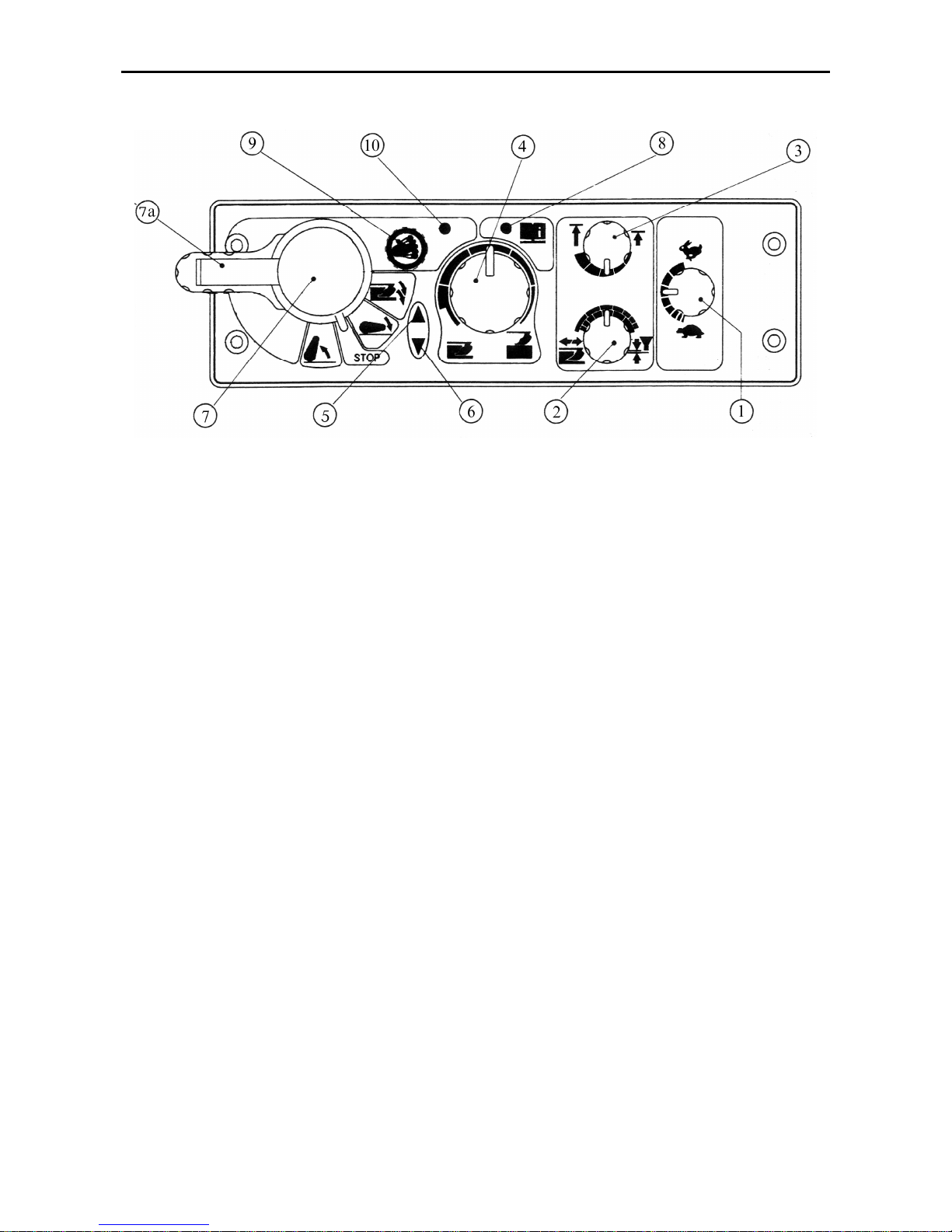
MTZ 1220.1/1220.3 Section D. Construction and Operation
D48
RHL Control Panel
Fig. D-36. RHL control panel
1 – lowering speed control handle (clockwise – quicker, anti-clockwise – slower); 2 – handle for selecting the
control method (clockwise – position one, anti-clockwise – draft one, intermediate – combination control); 3 –
handle for control of limitation of the hitch linkage lifting (clockwise – maximum lifting, anti-clockwise – minimum lifting); 4 – handle for controlling the soil treatment depth (clockwise – less depth, anti-clockwise – more
depth); 5 – hitch linkage lifting indicator (red); 6 – hitch linkage lowering indicator (green); 7 – hitch linkage
control handle (upwards – lifting, downwards – lowering, when pressing the handle more in the bottom position – deepening the implement during the soil treatment, intermediate position – disabled); 7a – interlock
switch (transportation) – mechanic interlock of the handle (7) in the top position by shifting the switch to the
right; 8 – diagnostic alarm (see “Fault Diagnostics”), 9 – damping button, 10 – damping indicator.
The procedure of control of the rear hitch
linkage is as follows:
• depending on the character of job, set
the control method by means of the
handle (2) (Fig. D-36);
• set the treatment depth and height of
the implement lifting in the transportation position by means of the handles
(4) and (3), respectively.
• to lower the hitch linkage, shift the han-
dle (7) to the bottom fixed position. In
this case, the indicator (6) goes out.
When performing the job, it is necessary
to set the optimum conditions of operation
of the mounted implement:
• combination of the control methods by
means of the handle (2);
• lowering speed by means of the handle
(1);
• soil treatment depth by means of the
handle (4).
In case of the draft control, the system limits automatically the correction frequency
to Hz in average.
In case of intense heating of the hydraulic
system oil, the correction frequency
should be reduced by shifting the handle
(2) to the position method of control and
the handle (1) – towards the turtle.
Page 97

MTZ 1220.1/1220.3 Section D. Construction and Operation
D49
In case of raising (“popping”) of the agricultural implement when passing through
the pressed soil areas gashes, deepen
the agricultural implement by pressing the
handle (7) more downward. On releasing
the handle (7) it will return to the fixed position of lowering. When it will be done,
the agricultural implement reaches to
mode of the preliminary specified depth
set by the handle (4).
To raise the agricultural implement, shift
the handle (7) to the upper position.
When lifting the implement, the indicator
(5) lights up.
ATTENTION! To avoid the failure of the
HLL pump, it is prohibited to operate
the tractor unless the indicator (5) goes
out after lifting the implement.
It is necessary to know the following peculiarities of starting the work with the
rear hitch linkage control system:
1. On starting the engine, the diagnostic
indicator (8) lights up to indicate the
serviceability and locking of the control
system;
2. To unlock the system, it is necessary
to set the handle (7) once to the working position (lifting or lowering). When
it will be done, the diagnostics indicator
(8) shall go out.
3. After unlocking the system when
switching on the same for the first time,
the automatic limitation of the speed of
lifting of the rear hitch linkage is provided for the safety reasons. Setting
the lever (7) to the “Lifting” position repeatedly disables the limitation of the
lifting speed.
4. The lifting and lowering of the rear
hitch linkage by means of the remote
control buttons on the fenders of the
rear wheels can be performed in any
control modes (the handles can be set
to arbitrary position). In this case, the
cab control system is blocked.
WARNING: When using the remote
control units, never stand between the
tractor and the implement ganged. To
avoid accidents, it is strictly prohibited
to use the buttons of mechanical
movement of the regulator solenoid
valves.
The work with the control system shall be
started in the sequence described in
paragraphs 2 and 3.
ATTENTION! To avoid more deepening of the agricultural implement, in
case of emergency stop of the tractor
the control handle (7) shall be set to the
“Neutral” position. After starting the
movement, shift the handle to the “lowering” position (the agricultural implement will e deepened to the preliminarily set depth).
In addition to the above functions, the
electronic control system of the RHL is
provided with the “damping” mode (damping of oscillations of the mounted agricultural implement in the transportation
mode).
The damping mode shall be enabled in
the following order:
• Set the handle (7) to the “lifting” position (when it will be done, the RHL will
be lifted to the top position and disengaged automatically);
• Press the “Dampind” button (9) (when
it will be done, the RHL will be lowered
from the top position by 3% from the
full stroke of the RHL).
ATTENTION!
1. The “Damping” mode can be only en-
abled, when the handle (7) is set to the
“Lifting” position.
2. When performing he field works
(ploughing, cultivation, etc.), the “Damping” mode shall be disabled.
Page 98

MTZ 1220.1/1220.3 Section D. Construction and Operation
D50
Fault Diagnostics
The BOSCH electronic hydraulic control system is provided with the self-testing capability
and issues the code information to the operator by means of the diagnostics indicator (8)
(Fig. E-35b) on the RHL control panel. In
case of absence of faults, the indicator is illuminated continuously after starting the engine. After upward or downward manipulations of the RHL control handle (7) (Fig. E35b), the indicator is switched off. On shifting
the control handle downwards, the green indicator (6) (Fig. E-35b) of lowering the RHL
lights up; on shifting the same upwards, the
red indicator (5) (Fig. E-35b) of lifting the
hitch linkage lights up.
Should there be some faults in the system (after
starting the engine) the diagnostics indicator
starts to issue the code information about the
fault and, if necessary, the operation of the system is locked.
The fault code is issued as a two-digit number, the first digit of which is equal to the
number of indicator blinks after long pause
and the second one – to the number of indicator blinks after short pause. For example,
long pause – three blinks of the indicator,
short pause – six blinks of the indicator. It
means that in the system there is a fault under the code “36”. Should there be several
faults, the system indicates the fault codes
one after another with separating them with a
long pause.
All the faults are divided into the three
groups: complex, medium and light.
On detecting complex faults, the control is
ceased and the system is switched off. The
system cannot be controlled from the control
panel and remote control buttons. The diagnostics indicator issues the fault code. After
elimination of the fault and starting the engine, the operation of the system is resumed.
In case of medium faults, the control is ceased
and the system is locked. The system cannot be
controlled from the main control panel, but can
be controlled from the remote control buttons.
The diagnostics indicator issues the fault code.
After elimination of the fault and starting the
engine, the operation of the system is resumed.
In case of light defects the diagnostics indicator issues the defect code. The system is
not locked and can be controlled. After elimination of the defect, the diagnostics indicator
goes out.
When the system detects a fault, proceed as
follows:
1. Stop the engine;
2. Set the controls on the main control panel
as follows
(Fig. E-35b):
• handle (7) for controlling the hitch link-
age – to the “off” position;
• handle (3) for controlling the lifting limi-
tation – to the “minimum lifting” position;
• handle (4) for controlling the soil treat-
ment depth – to the “minimum depth” position;
• handle (1) for controlling the lowering
speed – to the medium position;
• handle (2) for controlling the “draft –
position” mode – to the medium position.
3. Start the engine and, if there are no defects,
proceed to work. If the defects have not been
eliminated, perform the system diagnostics
and eliminate the faults.
The possible defects and methods of their
check-up are given in the table below.
The connection diagram of the RHL control
system is shown in Fig. E-37.
ATTENTION!
1. The electric connectors of the control sys-
tem of the hitch linkage shall be only disconnected when the engine is stopped
2. 2. The specified voltage values shall be
measured when the engine is running with
observing the safety precautions for working
with energized electric appliances.
3. 3. The contact numeration in the bundle
connectors is indicated on the parts of the
connector bodies
Page 99

MTZ 1220.1/1220.3 Section D. Construction and Operation
D51
List of possible defects and methods of their check-up
Defect
code
Defect description, possible
cause
Defect check-up method
Complex defects
11 Fault
in the circuit of control
the solenoid valve for lifting.
Open circuit in the winding
of the electromagnet (10) or
in the electromagnet control
bundle (Fig. D
-37).
Disconnect the bundle from the electromagnet and
check the electromagnet for open circuit b
y means of
a tester. The electromagnet resistance shall not ex-
ceed 2…4 . If the electromagnet is free of fault,
check the electromagnet control bundles for mechanical damage and check the wire from the elec-
tromagnet connector terminal to the terminal (2) of
the 25-
contact connector of the electronic unit for
breakage by means of a tester.
12
Fault in the circuit of control
the solenoid valve for lower
ing. Open circuit in the
winding of the electromagnet (9) or in the electromagnet control bundle (Fig
.
D
-37)
Disconnect the bundle from the electromagnet and
check the
electromagnet for open circuit by means of
a tester. The electromagnet resistance shall not exceed 2…4
. If the electromagnet is free of fault,
check the electromagnet control bundles for mechanical damage and check the wire from the elec-
tromagnet connector terminal to the terminal (14) of
the 25-
contact connector of the electronic unit for
breakage by means of a tester.
13
Fault in the circuit of control
the solenoid valve for lower
ing or lifting. Short circuit
in one of electromagnets or
be
tween the electromagnet
control wires in the bundle
(Fig. D
-37)
Disconnect the bundles from the electromagnets and
c
heck the electromagnets for short circuit by means
of a tester. The electromagnet resistance shall not
exceed 2…4 . Alternatively, measure the electromagnet consumption current when applying the volt-
age of 6 V to the electromagnet. The current shall not
exceed 3.2 . Disconnect the connector from the
electronic unit and check the terminals (2) and (14)
for short circuit (when doing this, the elec
tromagnets
shall be disconnected).
14
Fault in the control circuit of
the solenoid valves for low-
ering and lifting. Wire
breakage in the electromagnet control bundle (Fig
.
D
-37)
.
Check the system bundles for mechanic damages.
Disconnect the connectors from the electronic unit
and electromagnets and check the wire from the terminal (6) of the electronic unit connector to the termi-
nals of connectors of the electromagnets. Check the
presence of the supply voltage on the terminal
(5) of
the electronic unit connector (when doing this, the
engine shall be running). If the volt
age is absent,
check the reliability of connection in the single-
terminal block with violet wire on the right under the
dashboard and fuse. The fuse is located in the medium fuse block on the dashboard. The voltage is ap-
plied to the fuse after turning the switch of the starter
and instrumentation to the “instrumentation energized” position.
15
Fault of the remote control
Check the bundles from the remote control buttons
Page 100

MTZ 1220.1/1220.3 Section D. Construction and Operation
D52
Defect
code
Defect description, possible
cause
Defect check-up method
buttons. Short circuit between the wires
or locking
of one of the remote control
buttons. In this case, the
hitch linkage begins move
up- or downwards immediately after starting the engine (Fig. D
-37)
for mechanical damage. Disconnect each button in
turn until the defect is eliminated. When disconnecting the buttons, the engine shall be stopped. If the
defect does not disappear when the buttons are disconnected, it is necessary to disconnect the connector from the electronic unit and check the terminals
(10) and (12), (20) and (12) for short circuit by means
of a tester.
16 Electronic unit fault.
Stabilized supply voltage of
the control panel is below
the required level. Possibly,
short circuit in the connec-
tors of the sensors of force
and RHL p
osition due to
penetration of water into
the connectors (Fig. D
-37)
Disconnect the main control panel from the common
bundle. Measure the stabilized power supply voltage
on the contacts (6) (minus) and 4 (plus) of the control
panel connector, which shall be 9.5-10 V (after turn-
ing the switch of starter and instrumentation to the
“instrumentation energized” position). In case of
miss
ing or insufficient supply voltage, it is necessary
to check the reliability of connection of the electronic
unit connector. Di
sconnect in turn the sensors of
force and RHL position.
22
Fault of the position sensor.
Breakage of the sensor
wire or the sensor is not
connected or not adjusted
(Fig. D
-37)
Check:
• the reliability of connection of the electric connector to the position sensor (3) (Fig. E
-35c
);
•
the bundle connected to the sensor for mechanical
damage;
•
the correctness of setting the RHL eccentric, i.e. in
case of maximum lowering of the RHL, the sensor
shall be pressed to the minimum extent and vice
versa;
• the correctness of adjustment of the position sen-
sor (if the defect becomes apparent when the RHL
is in the bottom position, the sensor shall be
screwed in and it becomes apparent when the
RHL is in the top position, the sensor shall be
screwed out). The adjustment sha
ll be performed
when the RHL is in the top position.
Medium defects
23 Control panel fault. The po-
tentiometer (4) of the soil
treatment depth (Fig. D
-37)
is
faulty.
Check the reliability of connection of the connectors
of the control panel and electronic
unit as well as
check the bundle for mechanical damage. Check the
output voltage according to the electric diagram.
24 Control panel fault. The po-
tentiometer (3) of the top
RHL position (Fig. D
-37)
is
faulty.
Check the reliability of connection of the con
nectors
of the control panel and electronic unit as well as
check the bundle for mechanical damage. Check the
output voltage according to the electric diagram.
 Loading...