

Page 1
IN-WALL LOUDSPEAKER
SYSTEM
1 Mitek Plaza
Winslow, IL 61089
815-367-3000
800-225-5689
www.mtx.com
H615W
OWNER'S MANUAL
21A7558
Page 2

CONGRATULATIONS
We appreciate your choice of MTX In-Wall Speakers. Properly installed and operated, MTX In-Wall
Loudspeakers should provide years of worry free listening pleasure. It’s important that you follow each
step in this guide carefully to insure proper installation.
SPECIFICATIONS H615W
Frequency Response 50Hz-20kHz
+/- 3dB
Power Handling 40W RMS
80W Peak Music
Sensitivity (2.83V/1M) 86dB
Woofer Diameter 6-1/2"
Tweeter 1/2" Polycarbonate
Balanced Dome
Mounting Depth 3-1/16" (77.8mm)
Baffle Size 12"H x 8-5/8"W
(304.8mm x 219.1mm)
Cutout Size 10-3/4"H x 7-3/8"W
(273.1mm x 187.3mm)
PAINTING YOUR MTX IN-WALL SPEAKERS
MTX In-Wall Speakers are designed to accept all types of interior and exterior paints. Spray or roller
application should provide excellent results. A paint shield is included with all MTX In-Wall Speakers
to protect the speakers during the painting process. When paintng the grilles, simply remove the cloth
backing material before painting by pulling the material gently away from the grille. After the paint is dry,
reinsert the cloth backing material behind the grille mesh.
LOUDSPEAKER PLACEMENT
MTX In-Wall Speakers are designed to work within any interior decorating scheme. They can be installed
in virtually any location where flush mounting is possible. To maximize their sound performance however
certain guidelines should be followed. For the best stereo reproduction the two loudspeakers should be
placed an equal distance from your listening position and separated so that the speakers and the listener
form an equilateral triangle, with all sides of the triangle being the same length.
Listener
Diagram 1
For best stereo imaging, we recommend that the units be placed so that the tweeters are as close as
possible to the ear level of a seated listener. Also, the speakers should be placed so that the offset
tweeters are nearer to the inside edge of the speakers. The left and right speakers should have the
tweeter nearer to the center of the room. See Diagram 1.
Page 3
MTX WARRANTY INFORMATION
All MTX In-Wall Speakers purchased in the United States from an authorized MTX
dealer are guaranteed against defects in material and workmanship for a period ten years from
the date purchased by the end user, and limited to the original retail purchaser of the product.
Product found to be defective during that period will be repaired or replaced by MTX at no
charge. This warranty is void if it is determined that unauthorized parties have attempted repairs
or alterations of any nature. Warranty does not extend to cosmetics or finish. Before presuming
a defect is present in the product, be certain that all related equipment and wiring is functioning
properly. MTX disclaims any liability for other incurred damages resulting from product defects.
Any expenses incurred in the removal and reinstallation of product is not covered by this warranty. MTX's total liability will not exceed the purchase price of the product. If a defect is present,
your authorized MTX dealer may be able to effect repairs.
Proof of purchase is required when requesting service, so please retain your sales
receipt and take a moment to register your product on line at www.mtx.com.
INSTALLATION PREPARATION-NEW CONSTRUCTION
When installing the H615W into a newly built wall, please follow these instructions carefully.
1) Determine placement
Determine the location in the wall the speakers will be placed, using the recommendations in the
"Loudspeaker Placement" section.
2) Mount a Rough-In Kit
For best results, mount a RIK6W Rough-In Kit form Mitek Corp. (available at your MTX dealer). Follow
the instructions included with the kit.
3) The location is ready for dry wall
The RIK6W bracket provides a stable opening around which the drywall installer can cut out an opening,
providing a perfect location for the installation of the H615W.
INSTALLATION
STEP 1
Using a stud finder (available at low cost at most hardware stores) or other accurate method, locate
center point between two studs and mark. Using template provided, trace hole pattern on surface of
wall. Placing a bubble level on either the horizontal or vertical guidelines of template will assist you in
leveling the hole pattern.
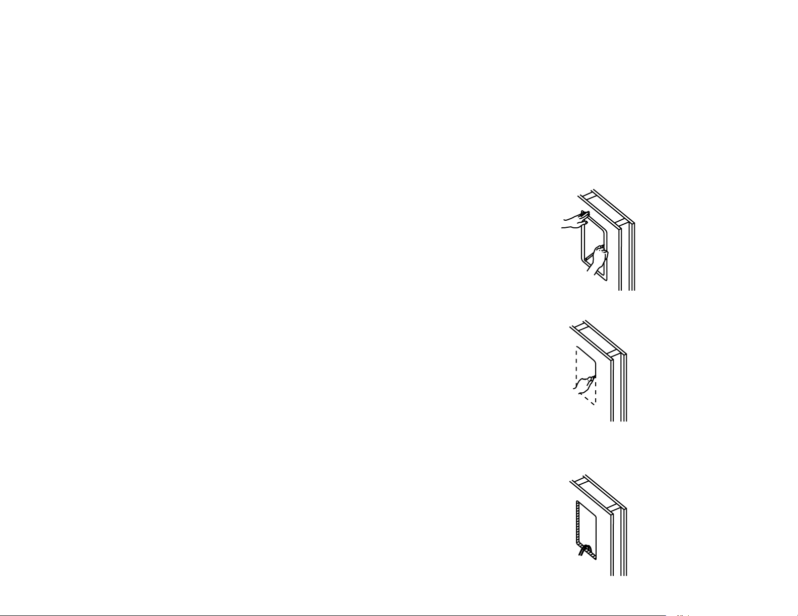
STEP 2
Using a sabre saw, keyhole saw or very sharp utility knife, cut hole in wall, following traced pattern.
STEP 3
Run loudspeaker wires to sound source location. There are several methods you can use to accomplish
wiring, depending on the construction characteristics of the room or house. You can add a professional
touch to your installation by using a speaker terminal plate at the source location. Leave sufficient amount
of wire at speaker location (8 to 10 inches) to complete connection.
Page 4

STEP 4
Attach loudspeaker wires to speaker terminals, observing correct polarity (positive to positive and
negative to negative), and position speaker frame into cutout as shown. Be careful not to pinch wires
in the process.
STEP 5
Carefully tighten the six mounting screws. This will cause the mounting wings to rotate out behind the
mounting surface and secure the speaker in place.
STEP 6
When you are satisfied the speaker is operational, affix grill. As grill is designed for a snug fit, you’ll need
to position one edge into slot first, and press or squeeze around perimeter of grill, while pushing leading
edges into grill slot.
SCHRITT 4
Verbinden Sie die Lautsprecherkabel mit den Terminals, wobei auf korrekte Polung (positiv zu positiv
und negativ zu negativ) zu achten ist, und schieben Sie den Lautsprecher-Rahmen wie gezeigt in den
Ausschnitt. Passen Sie auf, dass Sie dabei keine Kabel einklemmen.
SCHRITT 5
Ziehen Sie die sechs Montageschrauben vorsichtig an. Dies führt dazu, dass sich hinter der
Montageoberfläche die Einbauhalterungen drehen und den Lautsprecher festhalten.
SCHRITT 6
Wenn Sie sich vergewissert haben, dass der Lautsprecher funktioniert, befestigen Sie den Grill. Da der
Grill fest eingepasst werden soll, müssen Sie eine Kante zuerst im Schlitz platzieren und dann am Rand
des Grills pressen oder drücken, während Sie die Kanten in den Grillschlitz einführen.
The H615W speakers have a provision for mounting an infrared (IR) repeater in the baffle. The foam
plug next to the tweeter can easily be removed and an IR repeater mounted in that opening in the baffle.
The speaker can then be used as a control point for the audio system. We recommend the Atlas Sound
Model M-1A IR repeater for this application (www.Atlassound.com). Note: Additional wiring is required
for the operation of the IR repeater.
TECHNICAL ASSISTANCE
For additional technical assistance you can visit our website at www.mtx.com. Otherwise, our technical ser-
vice representatives can be reached by phone: 1-800-225-5689 or by E-mail: technical@mtx.com.
Die H615W-Lautsprecher ermöglichen es, einen Infrarot-Verstärker in der Schallwand zu installieren. Der
Schaumstopfen neben dem Hochtöner ist leicht entfernbar, und in diese Öffnung der Schallwand kann
ein Infrarot-Verstärker eingebaut werden. Der Lautsprecher kann dann als Kontrollpunkt für das AudioSystem dienen. Wir empfehlen hierfür den Atlas Sound Modell M-1A IR-Verstärker (www.Atlassound.
com). Hinweis: Für den Betrieb dieses IR-Verstärkers werden zusätzliche Kabel benötigt.
TECHNISCHE UNTERSTÜTZUNG
Weitere technische Hilfe finden Sie auf unserer Website bei www.mtx.com. Sie können unseren
technischen Kundendienst auch telefonisch erreichen: (USA) 1-800-225-5689 oder per E-Mail:
technical@mtx.com.
Page 5

INSTALLATIONSVORBEREITUNG - NEUBAU
Bei der Installation des H615W in eine Neubauwand sind folgende Anweisungen genau auszuführen.
1) Platzierung bestimmen
Legen Sie unter Hinzuziehung der Empfehlungen im Abschnitt „Lautsprecher-Platzierung“ fest, wo in der
Wand die Lautsprecher platziert werden sollen.
2) Einbau-Kit montieren
Die besten Ergebnisse bietet ein bei Ihrem MTX-Fachhändler erhältlicher RIK6W-Einbau-Kit von Mitek
Corp. Folgen Sie den dem Kit beiliegenden Anweisungen.
3) Die Stelle ist für GK-Platten bereit
Die Halterung RIK6W hat eine stabile Öffnung, um die herum ein Trockenbaumonteur eine Öffnung
schneiden kann, was eine perfekte Stelle für die Installation des H615W bietet.
INSTALLATION
SCHRITT 1
Verwenden Sie ein (preisgünstig im Fachhandel erhältliches) elektronisches Ortungsgerät oder eine
andere präzise Methode, um den Mittelpunkt zwischen zwei Ständerprofilen zu markieren. Tragen Sie
mit Hilfe der beiliegenden Schablone das Lochmuster an der Wand auf. Wenn Sie eine Wasserwaage
an die horizontalen oder vertikalen Richtlinien der Schablone halten, können Sie das Lochmuster gerade
anbringen.
SCHRITT 2
Verwenden Sie eine Pendel- oder Stichsäge oder ein sehr scharfes Gipskartonmesser und schneiden Sie
dem Muster folgend ein Loch in die Wand.
FÉLICITATIONS
Nous vous remercions d’avoir choisi des enceintes murales encastrables MTX. Correctement installées
et utilisées, ces enceintes vous donneront satisfaction pendant de longues années. Pour effectuer une
bonne installation, il est important de respecter strictement chaque étape de ce guide.
CARACTÉRISTIQUES H615W
Réponse en fréquence 50 Hz à 20 kHz
+/- 3 dB
Puissance admissible 40 W eff.
80 W crête dynamique
Sensibilité (2,83 V / 1 m) 86 dB
Diamètre haut-parleur de graves 6-1/2”
Haut-parleur d’aigus Polycarbonate 13 mm
Dôme équilibré
Profondeur de montage 3-1/16” (78 mm)
Dimensions écran acoustique 12” H x 8-5/8” L
(305 mm x 219 mm)
Dimensions de découpe 10-3/4” H x 7-3/8” L
(273 mm x 187 mm)
PEINTURE DES ENCEINTES MURALES ENCASTRABLES MTX
Les enceintes murales encastrables MTX ont été conçues pour recevoir tout type de peinture intérieure
ou extérieure. L’application au pistolet ou au rouleau donne en général d’excellents résultats. Un écran
permettant la protection lors de la peinture est fourni avec toutes les enceintes murales encastrables
MTX. Pour peindre les grilles, commencez par retirer avec précaution la toile acoustique de l’arrière de
la grille. Une fois la peinture sèche, remettez la toile derrière la grille.
PLACEMENT DES ENCEINTES
Les enceintes murales encastrables MTX ont été conçues pour s’intégrer à tout décor intérieur. Elles
peuvent être installées pratiquement partout où un montage encastré est possible. Toutefois, certaines
précautions doivent être prises pour optimiser les performances acoustiques. Pour obtenir la meilleure
reproduction stéréo, il faut placer les deux enceintes à égale distance de la position d’écoute et les
écarter de façon à ce qu’elles forment avec l’auditeur un triangle équilatéral (les trois côtés de la même
longueur).
SCHRITT 3
Verlegen Sie Lautsprecherkabel zur Soundquelle. Sie können zur Verkabelung verschiedene Methoden
verwenden, je nach Bauweise des Raums oder Gebäudes. Wenn Sie an der Soundquelle eine
Lautsprecher-Terminalplatte anbringen, dann sieht das sehr professionell aus. Lassen Sie an der
Lautsprecherseite genügend freies Kabel (20 bis 25 cm), um den Anschluss abzuschließen.
Auditeur
Figure 1
Il est conseillé de placer les enceintes de façon à ce que les haut-parleurs d’aigus soient le plus près
possible du niveau de l’oreille d’un auditeur assis, afin d’offrir la meilleure image stéréo. En outre, les
enceintes doivent être placées de façon à ce que les haut-parleurs d’aigus, décalés par rapport à l’axe
vertical, soient du côté intérieur des enceintes. Autrement dit, l’enceinte gauche et l’enceinte droite doivent
chacune avoir leur haut-parleur d’aigus le plus près possible du centre de la pièce. Voir la figure 1.
Page 6

PRÉPARATION DE L’INSTALLATION – CONSTRUCTION NEUVE
Pour installer le H615W dans un mur venant d’être construit, suivez attentivement les instructions cidessous.
1) Déterminez l’emplacement
Déterminez l’emplacement de montage des enceintes dans le mur conformément aux recommandations
de la section « Placement des enceintes ».
2) Installez un support de montage
Pour obtenir les meilleurs résultats, installez un support de montage Mitek Corp. RIK6W (disponible chez
les revendeurs MTX). Suivez les instructions accompagnant le support.
3) L’emplacement est prêt pour la pose de la cloison sèche
Le support RIK6W permet au poseur de cloison sèche d’effectuer une découpe précise pour l’installation
de l’enceinte H615W
INSTALLATION
ÉTAPE 1
Utilisez un détecteur de poteaux (en vente à bas prix, dans la plupart des quincailleries) ou une autre
méthode précise pour déterminer et marquer le point milieu entre deux poteaux d’ossature murale. À
l’aide du gabarit de perçage fourni, tracez les emplacements des trous sur le mur. Pour faciliter la mise à
niveau du gabarit de perçage, mettez un niveau à bulle sur son bord horizontal ou vertical.
ÉTAPE 2
À l’aide d’une scie sauteuse, d’une scie à guichet ou d’un couteau de bricolage bien tranchant, découpez
la paroi suivant le tracé.
HERZLICHEN GLÜCKWUNSCH
Wir freuen uns, dass Sie MTX-Wandlautsprecher gewählt haben. Wenn sie korrekt installiert und betrieben
werden, bieten Ihnen MTX-Wandlautsprecher jahrelang ungestörten Musikgenuss. Sie sollten unbedingt
allen Schritten in dieser Anleitung genau folgen, um eine korrekte Installation zu gewährleisten.
TECHNISCHE DATEN H615W
Frequenzgang 50 Hz - 20 kHz
+/- 3 dB
Belastbarkeit 40 W RMS
80 W Musik-Spitzenleistung
Empfindlichkeit (2,83 V/1 M) 86 dB
Tieftöner-Durchmesser 6 ½ Zoll
Hochtöner ½ Zoll Polykarbonat
Symmetrische Kalotte
Einbautiefe 3 1/16 Zoll (77,8 mm)
Schallwandgröße 12 Zoll H x 8 5/8 Zoll B
(304,8 mm x 219,1 mm)
Größe des Ausschnitts 10 ¾ Zoll H x 7 3/8 Zoll B
(273,1 mm x 187,3 mm)
ANSTREICHEN DER MTX-WANDLAUTSPRECHER
MTX-Wandlautsprecher können mit allen Innen- und Außenanstrichfarben lackiert werden. Das Auftragen
mit Walze oder Sprühgerät sollte zu hervorragenden Ergebnissen führen. Allen MTX-Wandlautsprechern
liegt eine Abdeckung bei, die die Lautsprecher während des Anstreichens schützt. Entfernen Sie vor dem
Anstreichen der Lautsprechergrills einfach die Stoffschicht, indem Sie das Material vorsichtig vom Grill
abziehen. Nach dem Trocknen der Farbe legen Sie den Stoff wieder hinter dem Grillgitter ein.
LAUTSPRECHER-PLATZIERUNG
MTX-Wandlautsprecher können an jede Inneneinrichtung angepasst werden. Sie können praktisch
überall eingebaut werden, wo eine bündige Montage möglich ist. Um die Klangleistung zu maximieren,
sollte man aber bestimmten Richtlinien folgen. Zur besten Stereo-Wiedergabe sollten sich die beiden
Lautsprecher in etwa gleicher Entfernung von Ihrer Hörposition befinden und so getrennt sein, dass die
Lautsprecher und der Zuhörer ein gleichseitiges Dreieck bilden.
ÉTAPE 3
Acheminez les fils des enceintes jusqu’à la source audio. Le câblage peut être effectué de plusieurs
façons, selon les caractéristiques de construction de la pièce ou de la maison. Pour donner à l’installation
un caractère professionnel, utilisez une plaque à bornes d’enceintes du côté de la source. Laissez une
longueur suffisante de fil (20 à 25 centimètres) du côté de l’enceinte pour effectuer le raccordement.
Zuhörer
Diagramm 1
Um das beste Stereo-Klangbild zu erreichen, sollten die Einheiten so platziert werden, dass sich
die Hochtöner möglichst nah an der Ohrhöhe eines sitzenden Hörers befinden. Zudem sollten die
Lautsprecher so platziert werden, dass die versetzten Hochtöner sich näher an der Innenkante des
Lautsprechers befinden. Bei den linken und rechten Lautsprechern sollte sich der Hochtöner näher zur
Raummitte befinden. Siehe Diagramm 1.
Page 7

PASO 4
Fije los cables de altavoz en las terminales de altavoz con la polaridad correcta (positivo a positivo y
negativo a negativo) y coloque el marco del altavoz en el corte de la pared como se muestra. No aplaste
los cables en el proceso.
ÉTAPE 4
Raccordez les fils des enceintes aux bornes en respectant la polarité (positif au positif et négatif au
négatif), et placez le châssis de l’enceinte dans la découpe comme le montre la figure. Veillez à ne pas
pincer les fils.
PASO 5
Apriete cuidadosamente los seis tornillos de montaje. Esto hace que las alas de montaje giren detrás de
la superficie de montaje y fijen el altavoz en posición.
PASO 6
Cuando esté satisfecho con el funcionamiento del altavoz, póngale la rejilla. Como la rejilla ha sido
diseñada para encajar apretadamente, debe colocar un borde en la ranura primero y luego comprimir el
perímetro de la rejilla a medida que va encajando los bordes en la ranura.
En el bafle de los altavoces H615W se puede montar un repetidor infrarrojo (IR). El tapón de espuma
junto al tweeter se puede quitar fácilmente y en su lugar se puede montar el repetidor infrarrojo. Luego
el altavoz se puede usar como punto de control para el sistema de audio. Recomendamos el repetidor
infrarrojo Atlas Sound modelo M-1A para esta aplicación (www.Atlassound.com). Nota: Se requiere
cableado adicional para hacer funcionar el repetidor infrarrojo.
ÉTAPE 5
Serrez avec précaution les six vis de montage. Cela fait tourner les ailettes de montage derrière la surface
de montage et permet la fixation de l’enceinte.
ÉTAPE 6
Lorsque vous jugez l’enceinte opérationnelle, mettez la toile acoustique en place. Elle est prévue pour un
ajustement serré et doit donc être mise en place d’un côté d’abord en insérant le bord dans la rainure.
Continuez avec les autres côtés, en poussant les bords dans les rainures.
Les enceintes H615W permettent le montage d’un répéteur infrarouge (IR) à l’intérieur de l’écran
acoustique. Le bouchon de mousse à côté du haut-parleur d’aigus peut facilement être enlevé pour le
montage du répéteur IR dans l’ouverture ainsi dégagée dans l’écran acoustique. L’enceinte peut être
utilisée comme point de commande du système audio. Pour cette application, il est conseillé d’utiliser
le répéteur IR Atlas Sound modèle M-1A (www.Atlassound.com). Remarque: Le fonctionnement du
répéteur IR nécessite un câblage supplémentaire.
ASISTENCIA TÉCNICA
Para obtener asistencia técnica adicional, vaya al sitio web www.mtx.com. De otro modo puede llamar
a los representantes de nuestro servicio técnico al 1-800-225-5689 o escribir por correo electrónico a
technical@mtx.com.
ASSISTANCE TECHNIQUE
Pour obtenir d’autres informations d’assistance technique, visitez notre site www.mtx.com. Vous pouvez
également contacter nos spécialistes d’assistance technique par téléphone au 1-800-225-5689 ou par
courriel à technical@mtx.com.
Page 8

FELICITACIONES
Le agradecemos que haya escogido los altavoces empotrados en la pared MTX. Cuando se instalan y
se hacen funcionar correctamente, los altavoces empotrados en la pared MTX le darán muchos años de
placer auditivo sin preocupaciones. Es importante que siga cuidadosamente los pasos especificados en
esta guía para que la instalación sea correcta.
ESPECIFICACIONES H615W
Respuesta de frecuencias 50 Hz a 20 kHz
+/- 3dB
Administración de potencia 40 vatios RMS
80 vatios máximo para músic
Sensibilidad:(2.83 V/1M) 86 dB
Diámetro de woofer 6-1/2 plg.
Tweeter 1/2 plg.
Domo equilibrado de policarbonato
Profundidad de montaje 3-1/16 plg. (77.8 mm)
Diámetro de bafle 12 plg. de alto x 8-5/8 plg. de ancho
(304.8 mm x 219.1 mm)
Diámetro de corte 10-3/4 plg. de alto x 7-3/8 plg. de ancho
(273.1 mm x 187.3 mm)
APLICACIÓN DE PINTURA EN LOS ALTAVOCES EMPOTRADOS EN LA PARED MTX
Estos altavoces empotrados en la pared MTX han sido diseñados para aceptar todo tipo de pinturas
interiores y exteriores. Las aplicaciones con rodillo o aerosol deben dar excelentes resultados. Los
altavoces empotrados en la pared MTX vienen con una máscara de pintura para protegerlos durante la
aplicación de pintura. Antes de pintar las rejillas, quíteles el respaldo de tela jalándolo cuidadosamente.
Una vez que la pintura se haya secado, vuelva a poner el respaldo de tela detrás de la rejilla.
UBICACIÓN DE LOS ALTAVOCES
Los altavoces empotrados en la pared MTX han sido diseñados para funcionar en cualquier esquema
de decoración interior. Se pueden instalar prácticamente en cualquier lugar en que se puedan montar al
ras. Sin embargo, para maximizar el rendimiento de sonido, se deben seguir ciertas pautas. Para lograr
la mejor reproducción estereofónica, los altavoces se deben colocar a la misma distancia del oyente y
deben separase de manera que formen un triángulo equilátero con la posición del oyente. Los tres lados
de un triángulo equilátero tienen la misma longitud.
PREPARACIÓN PARA LA INSTALACIÓN EN ESTRUCTURAS EN CONSTRUCCIÓN
Cuando instale el H615W en una pared en construcción, siga cuidadosamente las siguientes
instrucciones.
1) Determine la ubicación
Determine el lugar de la pared donde se van a colocar los altavoces siguiendo las recomendaciones de
la sección “Ubicación de los altavoces”.
2) Monte un bosquejador
Para obtener los mejores resultados, monte un bosquejador RIK6W de Mitek Corporation (que su
distribuidor MTX puede suministrarle). Siga las instrucciones que vienen con el bosquejador.
3) El lugar está listo para instalar la pirca
El bosquejador RIK6W presenta una abertura estable alrededor de la cual el instalador puede cortar la
pirca para crear el lugar perfecto para la instalación del H615W.
INSTALACIÓN
PASO 1
Con un localizador de parales (que se puede encontrar por un precio módico en la mayoría de las
ferreterías) u otro método preciso, ubique el punto central entre dos parales y márquelo. Con la plantilla
que se suministra, trace el contorno del agujero en la pared. Colocar un nivel de burbuja en la línea guía
vertical o la línea guía horizontal de la plantilla le ayudará a nivelar el contorno del agujero.
PASO 2
Con una sierra caladora, una sierra para hacer cerraduras de puertas o un cuchillo utilitario muy afilado,
haga un agujero en la pared siguiendo el contorno trazado.
Oyente
Diagrama 1
Para producir la mejor imagen estereofónica, recomendamos que las unidades se coloquen de manera
que los tweeters estén lo más cerca posible del nivel de los oídos del oyente sentado. Además, los
altavoces se deben colocar de manera que los tweeters –que no están centrados en la caja del altavoz–
queden hacia el centro de la sala. Vea el Diagrama 1.
PASO 3
Encamine los cables del altavoz hasta el lugar en que se va a ubicar la fuente de sonido. Hay varias
maneras de lograr esto, dependiendo de las características de construcción de la sala o de la casa. Usted
puede agregar un toque profesional a la instalación con una placa de terminales de altavoz en el lugar
en que se va a ubicar la fuente de sonido. Deje suficiente cable en el lugar en que está el altavoz (de 8
a 10 pulgadas) para completar la conexión.
 Loading...