

Page 1
Operation Chart
Function ABUS-VC3 Volume Control Module Multi-Source Multi-Zone Hub
System Off N/A System Off
Room 1 ON (zone 1) Touch any key in a zone
Module b
Input LED indicates input System ON status trigge
(same as
Volume (low level)
Room OFF Tap centre OFF button N/A
Sta
Room ON Tap volume UP/DOWN Hub already on
Backlighting ON
Volume (same as previous level)
Other rooms (zone 1) Status indicator ON If system is already on volume
(Off Button)return to previous setting level will return to previous setting
Input indicated
Room 2 (zone 1) Touch volume Up or Down N/A
Volume at low level
Zone 2 ON Tap button N/A
Vo
Volume Touch and hold either Up or Down button N/A
and left for volume down
Select Input 1-4 Tap left or
Room Off Tap centre button N/A
Turns off power m
System OFF Press centre button for three seconds Hub OFF
Turns all rooms and zones off Status light OFF (Green)
Power Supply LEDs Indicates power status (Red)
acklighting turns on components
last selected)
tus (OFF button) remains on N/A
Input indicated
lume (low level) unless previously on
Input indicates ripple right for volume up
right buttons to change input Changes input for that zone only
Four indicator lights (A & B outputs)
odule
Other rooms remain on
12v trigger ON to switch on source
r turns on
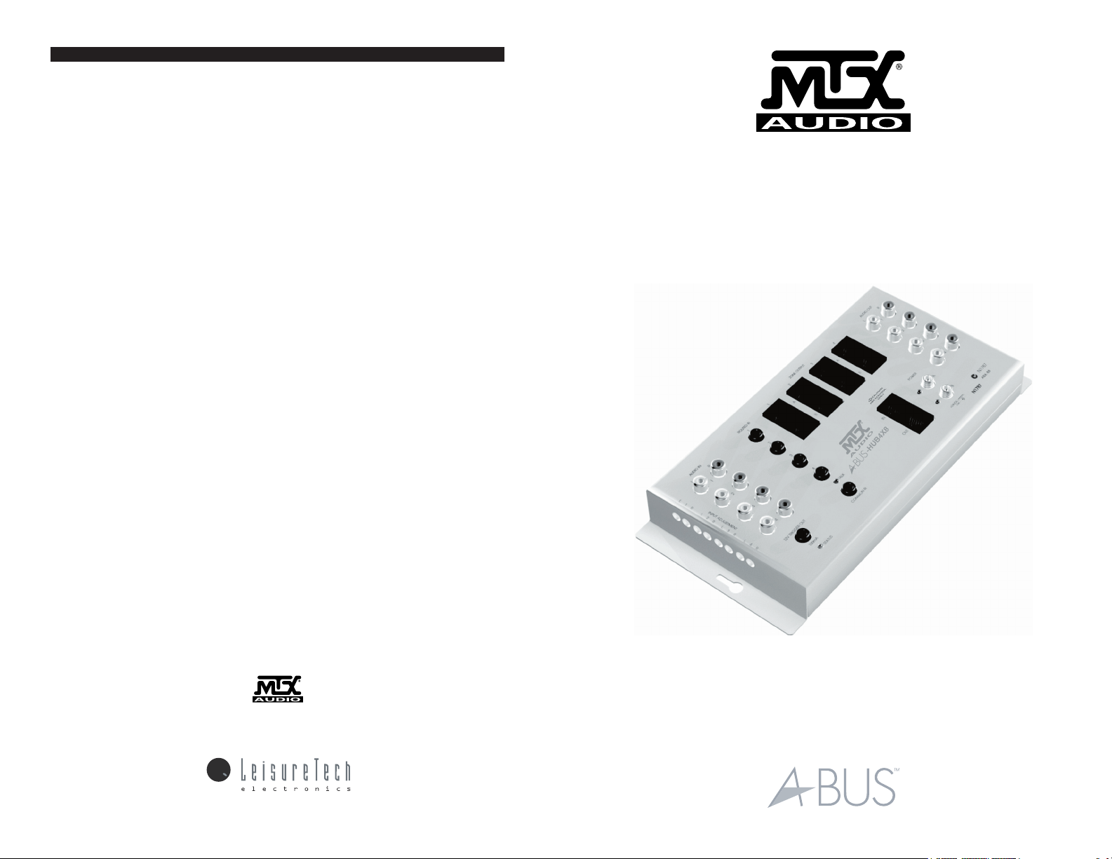
ABUS-HUB4X8
Multi-Source Multi-Zone Hub
A-BUS by MTX AUDIO products purchased in the United States from an authorized MTX dealer are
guaranteed against defects in material and workmanship for a period of two years from the date pur
chased by the end user, and limited to the original retail purchaser of the product. Product found to be
defective during that period will be repaired or replaced by MTX at no charge. This warranty is void if it is
determined that unauthorized parties have attempted repairs or alterations of any nature. Warranty does
not extend to cosmetics or finish. Before presuming a defect is present in the product, be certain that all
related equipment and wiring is functioning properly. MTX disclaims any liability for other incurred dam
ages resulting from product defects. Any expenses incurred in the removal and reinstallation of products
are not covered by this warranty. MTX's total liability will not exceed the purchase price of the product. If
a defect is present, your authorized MTX dealer may be able to effect repairs.
Proof of purchase is required when requesting service, so please retain your sales receipt and take a
moment to register your product online at mtx.com.
1 Mitek Plaza Winslow,IL 61089
815-367-3000 / 800-225-5689
A-BUS is a registered trademark of Leisure Tech Electronics Pty. Ltd.
All features and specifications are subject to change without notice. All
trademarks are property of their respective owners.
21A8667
-
-
Installation Manual
Page 2

Welcome
We hope you enjoy your ABUS system. Your ABUS component has been designed to give
high quality sound and be simple and functional to operate. All ABUS products bearing the
ABUS logo are made to the ABUS Standard, so when you connect an ABUS input device,
Hub or Volume Control Module they are compatible with each other. Some functions on
some manufacturer’s products may not work with other manufacturer’s products; however,
most features will be interoperable. All ABUS components are simple to service or upgrade,
so upgrading your system with components that offer improved features should be easy.
The ABUS Multi-Source Multi-Zone Hub is the core of your ABUS system. It is the input con
nection point for the source components. It also distributes power and sound to each room
Volume Control Module. It also repeats infrared (IR) commands to the source components.
Multiple Hubs may be used to expand the system to more than eight rooms.
ABUS-HUB4X8 Multi-Source Multi-Zone Hub
Audio Input [1] [2] - There are four stereo line-level source inputs [2]. Each input has indi-
vidual level adjustments [1] (left and right).
Trigger [3
] - The trigger is activated when any part of the system is on; its output is 12 volts
at 100mA.
Emitter Po
rts [5] [7] - Each source input has its routed emitter port [5], if more than one
component of the same type is used the Remote Control commands will not be confused.
Eg. 2 tuners. There is also a common emitter port [7] to control components that are com
mon to all zones.
Indicators [4] [6] [10] - The green status indicator [4] is on when the system (one zone or
all zones) is in operation. The red emitter indicator [6] flashes when there is an infrared data
command passing through the Hub. The power indicators [10] indicate when the correspond
ing power supply is on.
ABUS Compatibility
This product complies with the ABUS format. The ABUS format has been adopted by other manufacturers
who make variety of products that can give your system added flexibility. When looking to expand and/or
upgrade your home entertainment system, be sure to look for products that carry the ABUS trademark.
-
Specifications
HUB ABUS-HUB4X8 Four-Source, Multi-Zone Hub
Inputs Audio 4 x Stereo (RCA Sockets) 1 Vrms Adjustable (-6dB)
Control ABX Control (RJ-45
Power 2 x 2.5 mm DC Sockets +V Centre (Banks A and B)
Outputs Audio 4 x Stereo (RCA Sockets ) 1 Vrms
Control ABX Control (RJ-45 Socket)
ABUS 2 x
Trigger 12 VDC 100mA (3.5mm S
Infrared 4 x Routed, 1 x Common (3.5 mm So
Size (H x W x D) 4-1/8” (106mm) x 9-1/2” (241 mm) x 1-1/2” (38 mm)
4 Zones (RJ-45) (Bank A and B)
Socket)
ocket)
ckets)
-
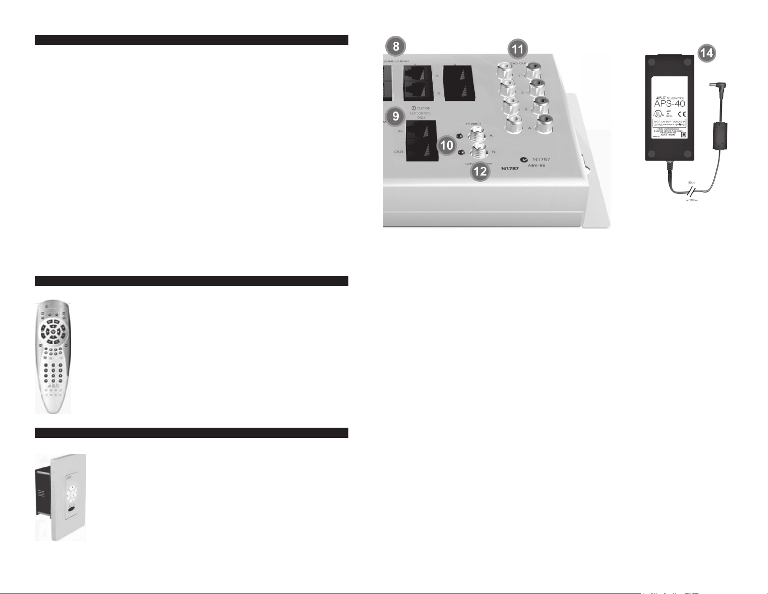
Power Supply APS-40 Power Supply (1 Req. for each ba
Inputs Power 120~240 VAC 50/60Hz 96w
-
Outputs Power 24 VDC 4A (2.5 mm DC plug)
Size (H x W x D) 1.4” (36.4 mm) x 2.8” (70 mm) x 6” (151.5 mm)
nk, 1 Supplied)
Page 3
Operation
The ABUS-HUB4X8 Multi-Source Multi-Zone Hub is controlled by ABUS infrared (IR) commands. There
are four audio inputs. When the Hub receives a command for any one of the four inputs in any zone, the
Hub will switch on. This will be indicated by the green status indicator. The 12 volt trigger will also activate.
If source components are activated by a power strip switched by the trigger, they will also activate. Each
zone must have one Volume Control Module with a keypad that includes buttons with ABUS functions
(inputs 1-4 or input Up/Down, Room Off and System Off commands). Alternatively, any Volume Control
Module containing an IR receiver may be used in conjunction with an ABUS remote that has these IR
commands built-in. Volume Control Modules without Room On/Off switches will activate when any Zone
is turned on. Other modules with individual ON/OFF capability require either an on command or a volume
Up/Down command to activate the module. These units will reset to a low volume level the next time the
system is turned on. The ABUS OFF command will turn off the Volume Control Module only. To turn the
whole system off, the SYSTEM OFF command must be used.
Infrared Repeater - Volume Control Modules that include infrared receivers will pass most infrared com
mands without difficulty. They will repeat standard 38 kHz commands and 56 kHz commands which are
often used in satellite receivers. Care should be taken to ensure the emitters are properly placed over the
receiver on the front of the component.
Infrared Remote IR Range - The operating range of your Remote Control will vary according to the light
conditions in the room, the quality of the IR remote (and battery condition) and the system design in the
components. In ideal conditions in areas with low light the range should be up to 20M (70ft), however, in
areas of high sunlight or lighting such as low-voltage lighting which can emit light in the infrared frequency
range the operating range can be substantially less. In direct sunlight the range may be reduced to as
little as 5M (15ft). Care should be taken when planning your ABUS system installation to locate the Volume
Control Modules in a position away from direct light and in a position convenient to the users to point the
IR Remote Control to the receiver in the module.
Note: Remote controls are not RF devices. The commands are sent by line-of- sight and will not go around
corners or through furniture or curtains.
IR Remote Control ABO-41RC
The ABO-41RC IR Remote Control is a very flexible device; it has been designed for easy
operation and to allow users to tailor the operation for more sophisticated operation. It
includes a code library for easy selection of codes and a dedicated ABUS code bank, all
buttons can learn commands and macros (including the bank buttons).
Quite often there are products not listed in the library so it is possible to learn commands
into the Remote Control from the ones supplied with the source components. It is also
possible to program multiple commands into one key (macros). For example; you could
program into the SAT bank button commands to turn on your television monitor, the cable
box and select the audio input in the ABUS
will then only need to press one button to turn the system on and set it up for normal TV
operation. Additional ABO-41RC Remote Controls can be purchased if required.
Note: Macro strings take time to emit, the operator should take care not to turn the Remote
Control away from the infrared receiver on the Volume Control Module or speaker before
all commands have been generated.
Multi-Source Multi-Zone Hub. The operator
ABUS-VC3 Keypad Volume Control Module
The ABUS-VC3 Keypad Volume Control Module was designed to work with intelligent
ABUS Multi-Source Multi-Zone Hubs using standard ABUS commands. The ABUSVC3 provides the following functions:
Volume Up/Down
Input selection Up/Down
Room Off
System Off
Infrared repeating
Status indication
Infrared talkback
Volume level change id
entification
-
ABUS Outputs [8 A & B] - Each of the ABUS Outputs provides the power, audio and data
signals to feed a Volume Control Module. There are four output zones; each zone may independently select from any of the four sources. Each zone has two outputs, bank ‘A’ and bank
‘B’. One power supply is supplied with the Hub to power the outputs for bank A. [14] A second
power supply can be added to power the bank B or alternatively the second output can used
as an expansion port to feed one or more single source Hubs with expansion capability.
CAUTION: Only an approved ABUS 4-Room Power Supply [14] should be used. Substitutes
which may appear to be suitable are not recommended and will void the warranty.
DC Power Input Sockets [12] - There are two power sockets one for each output bank ‘A’
and ‘B’.
ABUS Control Ports (In/Out) [9] - Another ABUS-HUB4X8 Multi-Source Multi-Zone Hub
may be connected to this port if additional zones are desired. Up to four ABUS-HUB4X8
Multi-Source Multi-Zone Hub may be connected together, providing for a maximum of 16
zones. CAUTION: The control ports pass the control data between Multi-Source Multi-Zone
Hub and may not be used for any other purpose.
Note: The ABX Control [9] and audio expansion [11] ports must be connected to additional
hubs for proper function.
Audio Outputs [11] - The RCA Audio Outputs allow sharing of the audio sources with the
main system amplifier or to expand to additional ABUS-HUB4X8 Multi-Source Multi-Zone
Hubs. The audio levels adjusted at the input will be the same on the output so no level adjustment will be required on the additional Hub(s).
IR Remote Control [13] - One ABUS ABO-41RC Remote Control handset is supplied with
the ABUS-HUB4X8 Multi-Source Multi-Zone Hub. This Remote Control includes a dedicated
ABUS bank and includes keys for most standard functions including color cable box buttons (not used in all countries). The Remote Control has a code library built in; however,
it is capable of providing advanced functions for user convenience. All keys have learning
capability; all keys can also learn multiple commands (macros) including the mode keys. See
separate instructions.
Page 4

Setup
Input Level Adjustments [1] - The ABUS-HUB4X8 Multi-Source Multi-Zone Hub is supplied
with the input level adjustments set fully clockwise. If one source is noticeably louder than
the other sources, turn both the Left and Right Input Level Adjustments for that source coun
terclockwise, reducing the input level to match the volume level of the lowest source. Repeat
this procedure for any other sources that are too loud, until all sources are balanced. Some
audio sources such as computer sound cards may have very low output. In these cases it is
recommended that the volume be turned up at the output of the source. Check for either a
physical volume control or an IR remote volume control on such devices.
Trigger Output [3] - The Trigger Output may be used to activate a relay or other device that
responds to a steady-state 12volt trigger signal. This output may be used to power a Power
Strip, which may be used to power the source components. When the System Off command
is pressed, the 12 Volt Trigger Output will be turned off. Source components that are plugged
into a trigger-controlled power strip will be switched off. Care should be taken to ensure that
components will not lose their memories (clocks, etc. or presets) after long periods of nonuse.
Infrared (IR) Emitter Ports [5] [7] - There are 5 emitter ports, 4 are routed ports. The routed
outputs will only emit commands from the zone that has selected that source. This will allow
more than one source device with the same code set to be used. If this is the case, lightblocking emitter caps should be used to prevent infrared commands from straying into the
infrared receivers of adjacent components. The common emitter port will generate all com
mands from any zone with infrared capability. Some components have an IR IN socket on the
back, it is recommended that this direct connection be used.
CAUTION: Do not confuse a serial data port connection with an infrared port.
TIP 1. Finding the infrared receiver location in some components can be difficult. To find the
right place, place a large card with a hole the size of a folder punch hole in it over the front
of the component and while generating a command from the components Remote Control
handset move the card around until the unit responds to the command.
2. In situations where the unit is not responding to the commands from the emitter or if the
response is erratic the signal level may be too high. If the operation improves when the emit
ter is held away from the component a filter will be required such as some exposed camera
film.
3. Some source components may not respond to repeated infrared commands. This is rare
and may require a change in component.
Status [4] - The green status light indicates when the system is turned on. The system is ac
-
-
-
tivated when the Hub receives a source-select command from any zone. Once a command
has been received by the Hub to activate, a 12 volt signal will be available at the Trigger
Output [3]. Other zones may be activated at any time. Individual Volume Control Modules
have to be turned on separately before sound can be heard. Regardless of which Volume
Control Modules are on or off, the 12 volt trigger will remain active until a System Off command is sent to the Hub.
Infrared Talkback [6] - The Red Talkback indicator flashes when an infrared data command
is passing through the Hub.
Power [12] - The two red power lights indicate when the power supplies connected to bank
A or bank B are active. These indicators do not indicate the system is active (see System
Indicator [4]).
System Design
The ABUS-HUB4X8 Multi-Source Multi-Zone Hub is compatible with any ABUS Volume Control Module; however, some Volume Control Modules do not have the capability to control
the ABUS-HUB4X8 Multi-Source Hub directly from keypad buttons. We recommend using
only Volume Control Modules with IR receivers built in, so that you will be able to control
the ABUS-HUB4X8 Multi-Source Multi-Zone Hub by pointing an ABUS IR Remote at the
Volume Control Module, which will repeat the IR commands to the ABUS-HUB4X8. ABUS is
a very flexible system, it allows for many variations not normally possible in traditional multiroom systems. For instance; it is possible to mix Multi-Source Multi-Zone Hubs with single
source Hubs. There are many reasons you may want to do this, the most common reason
is because in an open plan house you may have interconnecting areas which are acousti
cally the same (family rooms, dining rooms and kitchens). So if you change the source in
one area the other rooms can track the same source. Another example is bedrooms with
bathrooms. In the master bedroom, the full-function Volume Control Module would normally
be used; however, in the bathroom a less-expensive Volume Control Module may be all that
is needed. The Multi-Source Multi-Zone Hub has a second output port (the second bank
requires a separate power supply) in each zone to cater for this requirement. If additional
areas are required within the zone the second output port may be connected to a separate
4-Room Hub to expand that zone.
-
-
 Loading...