

Page 1
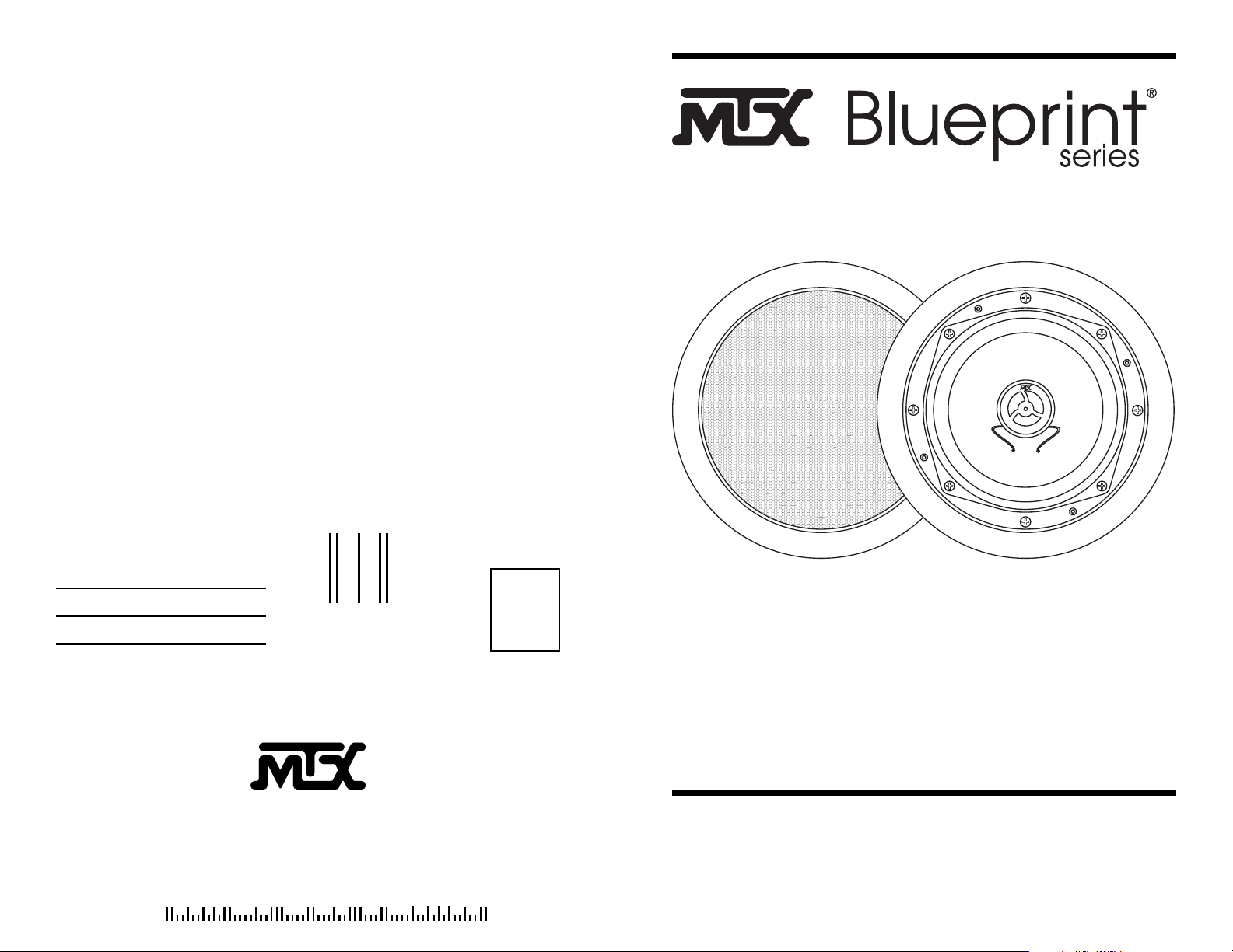
MODEL 510CM
WATER RESISTANT
IN CEILING LOUDSPEAKER
OWNERS MANUAL
FIRST
CLASS
STAMP
HERE
4545 E BASELINE RD
PHOENIX AZ 85040-6400
21A2692
Page 2

CONGRATULATIONS
We appreciate your choice of MTX Blueprint Series In-Ceiling Loudspeakers.
Properly installed and operated, MTX In-Ceiling Loudspeakers should provide
years of worry-free listening pleasure. It’s important that you follow each step
in this guide carefully to insure proper installation. If you have any questions
regarding MTX In-Ceiling Loudspeakers, please call us at 1-800-223-5266.
PAINTING YOUR MTX IN-WALLS
MTX In-Ceiling speakers are designed to accept all types of interior and exte-
rior paints. Spray or roller application should provide excellent results. A paint
shield is included with all Blueprint Series In-Ceiling speakers to protect the
speakers during the painting process.
SPECIFICATIONS
Frequency Response
Impedance
Nom. Power Handling
Total Power Handling
Sensitivity
Woofer Diameter
Tweeter
Mounting Depth
72-20kHz
8 Ohms
30 Watts
120 Watts
85dB
5 1/4”
1/2” Polycarbonate Dome
3 5/16”
Specifications subject to change without notice.
W ARRANTY
MTX Blueprint Series In-Ceiling Loudspeakers are guaranteed against
defects in parts and workmanship for a period of ten (10) years from the date
of purchase. Speakers found defective during that period will be repaired by
MTX without char ge for parts.
This warranty is void if it is determined that unauthorized parties have
attempted repairs or alterations of any nature. Before assuming that a defect is
present in the loudspeakers, be certain that all associated equipment is operat -
ing properly .
If a defect is present, your authorized MTX dealer may be able to
ef fect repairs. If not, you are responsible for providing transportation to the fac -
tory. Y our MTX dealer can recommend the safest method of transportation.
Proof of purchase is required when requesting service, so please retain your
sales slip.
Specifications subject to change without notice.
(Cut out on dotted line and mail to address on reverse side.)
W ARRANTY REGISTRATION
To r egister your pur chase and insur e your investment, please fill out and r eturn this car d.
NAME_______________________________AGE______________
ADDRESS______________________________________________
______________________________________________
MODELPURCHASED MODEL 510CM
D ATE PURCHASED____________________
DEALER NAME ________________________________________
PURPOSE: Main Music Listening Background V ideo/surround
Other__________________________________________
ROOM(S) INSTALLED _____________________________________
INSTALLED BY __________________________________________
H O W DID YOU FIRST LEARN OF MTX IN-WALLS?
Dealer Friend Magazine Radio Newspaper Other
Page 3

OTHER BLUEPRINT SERIES PRODUCTS FROM MTX
MTX offers a wide assortment of audio components. Ranging from in-wall speakers to
amplifiers to accessories. Each component is value engineered and must meet strict
quality control standards before it becomes part of the MTX product line.
Listed below you will find a sampling of MTX components available from your authorized Blueprint Series dealer.
IN-WALL LOUDSPEAKERS
MODEL 520W
5-1/4” Two-Way In-Wall Speaker
1” Soft Dome Tweeter
8 Ohm Impedance/84dB Sensitivity
53Hz-20kHz Frequency Response
50 Watts RMS/160 Watts Total
11”H x 7-1/2”W x 2-1/2”D
MODEL 620W
6-1/2” Two-Way In-Wall Speaker
1” Soft Dome Tweeter
8 Ohm Impedance/85dB Sensitivity
43Hz-20kHz Frequency Response
55 Watts RMS/180 Watts Total
12-1/16”H x 8-9/16”W x 2-7/8”D
MODEL 820W
8” Two-Way In-Wall Speaker
1” Soft Dome Tweeter
8 Ohm Impedance/86dB Sensitivity
33Hz-20kHz Frequency Response
60 Watts RMS/200 Watts Total
14-1/16”H x 10-1/16”W x 3-1/2”D
MODEL 502W
5-1/4” Two-Way In-Wall Speaker
1/2” Polycarbonate Dome Tweeter
8 Ohm Impedance/84dB Sensitivity
53Hz-20kHz Frequency Response
45 Watts RMS/140 Watts Total
11”H x 7-1/2”W x 2-1/2”D
MODEL 602W
6-1/2” Two-Way In-Wall Speaker
1/2” Polycarbonate Dome Tweeter
8 Ohm Impedance/85dB Sensitivity
43Hz-20kHz Frequency Response
50 Watts RMS/160 Watts Total
12-1/16”H x 8-9/16”W x 2-7/8”D
MODEL 600WM
6-1/2” Water Resistant Co-Axial In-Wall Speaker
1/2” Polycarbonate Dome Tweeter
8 Ohm Impedance/88dB Sensitivity
64Hz-20kHz Frequency Response
35 Watts RMS/140 Watts Total
8-5/8”H x 8-5/8”W x 2-3/4”D
SPEAKER/AMPLIFIER SELECTOR
LPS-600
Accommodates up to 6 pair of speakers
Handles up to 250 Watts/channel continuous (RMS)
Impedance Protection Circuitry
Low profile-full size component
Two-piece, plug in connectors on the rear panel
Accommodates up to 14 gauge wire
TV-5 UL Approved Switches
A/B Amplifier and Input Selector
ACCESSORIES
VC-30B/VC-30W
Decora-Style Volume Control (Bone or White)
10 Step 25 Watts per channel (RMS) 150 Watts Peak
AB-1SB/AB-1SW
Decora-Style A/B Switch (Bone or White)
PCK65C
Pre-Construction Kit for Model 610RCM
PCK85C
Pre-Construction Kit for Model 810RCM
LOUDSPEAKER PLACEMENT
Blueprint Series Loudspeakers are designed to work within any interior decorat-
ing scheme. They can be installed in virtually any location where flush mount-
ing is possible. To maximize their sound performance however certain guidelines
should be followed. For the best stereo reproduction the two loudspeakers should
be placed an equal distance from your listening position and separated so that the
angle between them, at the listening position, is between 40 and 60 degrees.
Page 4

STEP 1
Using a stud finder (available at low cost at most hardware stores) or other accurate method, locate center point between two joists and mark. Using template
provided, trace hole pattern on surface of ceiling.
STEP 2
Using a sabre saw, keyhole saw or very sharp utility knife, cut hole in wall, following traced pattern.
STEP 3
Run loudspeaker wires to sound source location. There are several methods you
can use to accomplish wiring, depending on the construction characteristics of
the room or house. You can add a professional touch to your installation by using
a speaker terminal plate at the source location. Leave sufficient amount of wire
at speaker location (8 to 10 inches) to complete connection.
STEP 4
Attach loudspeaker wires to speaker terminals, observing correct polarity, and
position speaker frame up into cutout. Be careful not to pinch wires in the
process.
STEP 5
Carefully tighten the four mounting screws. This will cause the mounting wings
to rotate out behind the mounting surface and secure the speaker in place.
STEP 6
After the speaker panel is secured tightly, test for sound. When you are satisfied
the speaker is operational, affix grill. The Model 510CM grill can be installed
into the speaker frame for either a standard flush mount cosmetic appearance or
a recessed look similar to a coilex type of light fixture. After deciding which look
is preferred press the grill into the frame until the leading edge is flush.
 Loading...