

Page 1

RTLDBP
Digital Bass Processor
Page 2

PRODUCT INFORMATION
Model #
Serial #
Dealer’s Name
Date of Purchase
INTRODUCTION
Thank you for purchasing this MTX Digital Bass Processor. Proper installation matched with MTX
ampliers, speakers, and subwoofers provide superior sound and performance for endless hours of
enjoyment whether you are waking the neighbors or just out enjoying your tunes. Congratulations
and enjoy the ultimate audio experience with MTX!
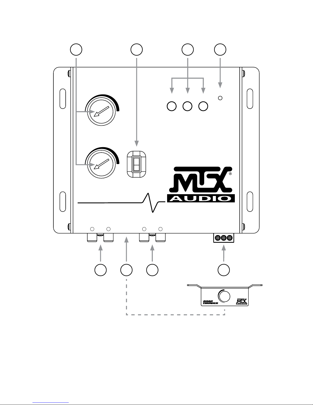
CONTROL FUNCTIONS
1. Inputs - The inputs use a balanced input circuit to help minimize induced noise. They are also
designed to handle very high signal voltages up to 15 volts.
2. Outputs - The outputs should be connected to a component auch as a crossover, equalizer, or
amplifer. Note: The RTLDBP should be inline before a crossover.
3. Dash Remote Control Connector
4. Power Connector
5. Para-Bass Controls - The two knobs control the Para-Bass functions of the RTLDBP. The SWEEP
knob picks the desired center frequency to be maximized. The WIDE knob adjusts how wide of a
frequency range the RTLDBP will effect.
6. PFM Subsonic Filter Switch - The RTLBDP utilizes a PFM Subsonic Filter Switch which will help
with speaker control and power management. The PFM Subsonic Filter Switch comes with three
frequency selections: 35Hz / 50Hz / 80Hz. On most systems, setting the switch at 35Hz is ne. A
higher frequency setting will provide even more protection to your system. Often a higher
frequency actually sounds louder and cleaner.
7. Bass Maximizer Indicators: These three LED indicators ash when the bass maximization circuit
is activated.
8. Power On LED
9. Input Grounding Jumpers - For most systems the jumper can be left in the BALANCED position. In
some systems, the source unit may look for a ground through the RCA connectors. In this event,
the jumpers should be moved to the UNBALANCED position.
10. Ground Isolation Jumpers - Occasionally alternator whine may appear in a system because the
source unit and amplier may use different grounding. Alternate grounding connections have
been provided to help in this situation. Make sure the system is turned OFF before these jumpers
are removed.
11. Bass Output Control Jumpers - Not all systems are designed the same. Some are designed
strictly for SPL (sound pressure level) while other are a little more tame. The Bass Maximizer
circuit can either increase or decrease the signal voltage of the Bass Restoration Circuit.
Depending upon the system, these jumpers may be changed to a higher or lower setting to
maximize the bass output and protect your speakers. In most systems the factory setting should
be ne. It is recommended to try the factory setting rst.
Page 3
Remote Control
RTLDBP
MAX BASS CONTROL
POWER
WIDE
SWEEP
MIN
MAX
MIN
MAX
35Hz
50Hz
80Hz
BALANCED
INPUT
DASH
REMOTE
OUTPUT
+12V - REM - GND
L R L R
DIGITAL BASS PROCESSOR
1 3 2 4
86 75
CONTROL FUNCTIONS
Page 4

Remote Control
RTLDBP
MAX BASS CONTROL
POWER
WIDE
SWEEP
MIN
MAX
MIN
MAX
35Hz
50Hz
80Hz
BALANCED
INPUT
DASH
REMOTE
OUTPUT
+12V - REM - GND
L R L R
DIGITAL BASS PROCESSOR
POWER CONNECTION
• B+(12V) - Connect the red wire to the car battery or other power source.
• Remote - Connect the orange wire to the remote activating (12V DC) wire of the car stereo or
equalizer.
• GND - Connect the black wire to the car chassis for ground connection.
BlackRed
Orange
Battery
+ –
Page 5

MAX BASS CONTROL
POWER
WIDE
SWEEP
MIN
MAX
MIN
MAX
35Hz
50Hz
80Hz
BALANCED
INPUT
DASH
REMOTE
OUTPUT
+12V - REM - GND
L R L R
DIGITAL BASS PROCESSOR
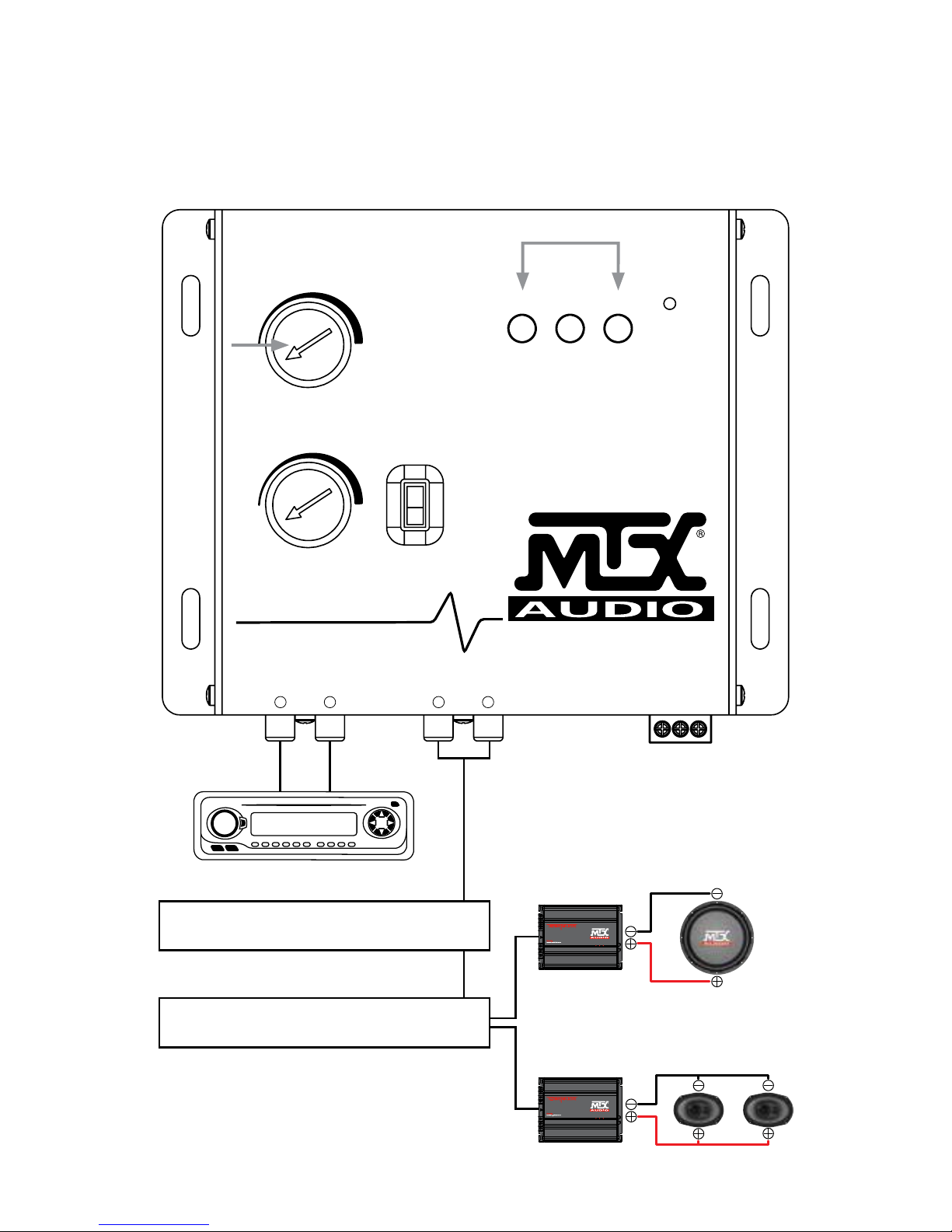
SIGNAL CONNECTION
For signal connection, the output RCA connectors should be connected to the next component after
the RTLDBP, such as a crossover, equalizer, or amplier.
Equalizer
Crossover
4Ω
4Ω4Ω
4Ω
4Ω
4Ω
4Ω
4Ω
4Ω
Subwoofer
Speakers
Amplier
Amplier
Page 6

ADJUSTING THE PARA-BASS CONTROLS
The bass response in a system is affected by four factors:
1. The acoustics of the vehicle
2. The location of the speakers
3. The music being played
4. The speakers and speaker enclosures
The RTLDBP was developed to help restore any low frequencies lost due to varioations in the
recording process. However, the acoustics of various environments are different.
The SWEEP control allows the user to select a center frequency (the frequency most affected)
between 27 and 63 Hz. The WIDTH control then allows the user to control the shape of the lter
centered around the SWEEP frequency.
SETTING THE BASS OUTPUT CONTROLS
The RTLDBP is a powerful bass component. This device is equipped with several different Bass
Output selections. If the settings need to be changed, please use the chart below for guidance. It is
recommended to listen to the factory setting before changing the Bass Output settings.
Recommended Settings:
Setting Amplier Input Voltage Minimum Speaker Size
2.5V 3V or Less 8"
5V 5V or Less 10"
7.5V 7.5V or Less 12"
10V 10V or Less
FEATURES
Bass Driver - The RTLDBP contains a Bass Driver circuit that accurately recreates and injects low
frequency information back into the signal path. This means that the RTLDBP will give more bass
impact to music sources, even older compact discs and tapes.
Bass Equalization Circuit - The RTLDBP has a unique equalizaition circuit that contours the restored
bass to the speaker systems.
Dash Mount Remote Control - The RTLDBP comes with a Dash Mountable Remote Control that allows
the user to control the bass processor without having to leave the driver’s seat. The LED indicator will
become brighter as the bass is increased, and will dim as the bass is decreased.
Bass Maximizer Indicator - These three LED indicators will ash when the bass maximization circuit
has been activated.
PFM Subsonic Filter Switch - This unique feature has the ability to ne tune the bass response of any
system. Why waste power on nasty subsonic information when the PFM Subsonic Filter Switch can
help to clean things up?
Bass Output Control - The RTLDBP has the ability to produce large amounts of deep, mind blowing
bass without damaging the speakers. The Bass Output Control circuit allows the RTLDBP to maximize
the bass output of any audio system while restraining destructive bursts.
Page 7

SPECIFICATIONS
• Maximum Input Level: 15V RMS
• Maximum Output Level: 13.5V Peak
• Frequency Response: 10Hz - 100KHz
• THD: 0.003%
• Signal to Noise Ratio: -130dB
• Balanced Input Noise Rejection: >60dB
• Input Impedance: 10KΩ
• Output Impedance: 150Ω
• Power Supply: High Headroom PWM
• Power Draw: 150mA
• Recommended Fuse Rating: 1 Amp
TROUBLESHOOTING
The unit does not turn on and / or the power indicator LED is not illuminated:
1. Make sure that the B+ and GND wires are not reversed.
2. Make sure that all power wires are properly connected and have the appropriate potential
(11-16V).
3. Make sure that all fuses are intact.
Experience high audible distortion or low output volume:
1. Make sure that the input and output levels are set correctly. The input should match the source
and the output should match the sensitivity of the host.
2. Make sure that the crossover settings are correct. For high “Q” systems, set the crossover half
an octave above the desired point. For low “Q” systems, set the crossover one octave or more
above the desired point.
Experience whining or engine noise:
1. Make sure that the GND connection is secure and that the conductor (wire) is not too thin and
unnececessarily long.
2. Make sure that the B+ wire is not too thin and unnecessarily long.
3. Change the power source. Try taking power from a different point.
Page 8

INFORMACIÓN DE PRODUCTO
Número de Modelo
Número de Serie
Nombre de Comerciante
Fecha de Compra
INTRODUCCION
Gracias por adquirir este procesador MTX Digital Bass. La instalación correcta emparejado con
amplicadores, altavoces MTX y subwoofers proporcionan un sonido superior y rendimiento para
interminables horas de diversión si usted está despertando a los vecinos o simplemente disfrutando
de sus canciones. Felicitaciones y disfrutar de la experiencia de audio denitiva con MTX!
FUNCIONES DE CONTROL
1. Entradas - Las entradas utilizan un circuito de entrada equilibrada para ayudar a minimizar
el ruido inducido. También están diseñados para manejar muy altos voltajes de señal de hasta 15
voltios.
2. Salidas - Las salidas deben estar conectados a un componente, como un crossover, ecualizador,
o amplicador. Nota: El RTLDBP debe estar en línea antes de un crossover.
3. Control remoto que se monta al tablero
4. Conector de alimentación
5. Controles Para-Bass - Los dos mandos controlan las funciones para-Bass del RTLDBP. El mando
BARRIDO recoge la frecuencia central deseada para maximizar. El mando ANCHA ajusta el
ancho de un rango de frecuencia de la RTLDBP afectará.
6. PFM interruptor ltro subsónico - El RTLBDP utiliza un conmutador de ltro subsónico PFM que
ayudará con el control de altavoz y de gestión de energía. El interruptor de ltro subsónico PFM
viene con tres selecciones de frecuencia: 35Hz / 50Hz / 80Hz. En la mayoría de los sistemas,
poniendo el interruptor en 35Hz está bien. Un ajuste de frecuencia más alta proporcionará aún
más protección a su sistema. A menudo, una mayor frecuencia en realidad suena más fuerte y
más limpio.
7. Bajo indicadores maximizador: Estos tres indicadores LED parpadean cuando se activa el
circuito de la maximización de graves.
8. Encendido LED
9. Los puentes de conexión a tierra de entrada - Para la mayoría de los sistemas el puente se puede
dejar en la posición de equilibrio. En algunos sistemas, la unidad fuente puede buscar un
terreno a través de los conectores RCA. En este caso, los puentes deben moverse a la posición
desequilibrada.
10. Puentes de aislamiento de tierra - Ocasionalmente zumbido del alternador puede aparecer en un
sistema porque la unidad de la fuente y el amplicador pueden utilizar diferentes a tierra.
Conexiones a tierra alternativos se han proporcionado para ayudar en esta situación. Asegúrese
de que el sistema esté apagado antes de retirar estos puentes.
11. Puentes de control de salida de graves - No todos los sistemas están diseñados de la misma.
Algunos están diseñados exclusivamente para SPL (nivel de presión sonora), mientras que otros
son un poco más dócil. El circuito Bass Maximizer puede o bien aumentar o disminuir el voltaje
de la señal de la Restauración Circuito Bass. Dependiendo del sistema, estos puentes se pueden
cambiar a un ajuste más alto o más bajo para maximizar la salida de graves y proteger sus
altavoces. En la mayoría de los sistemas de la conguración de fábrica debe estar bien. Se
recomienda probar el establecimiento de la primera fábrica.
Page 9

Remote Control
RTLDBP
MAX BASS CONTROL
POWER
WIDE
SWEEP
MIN
MAX
MIN
MAX
35Hz
50Hz
80Hz
BALANCED
INPUT
DASH
REMOTE
OUTPUT
+12V - REM - GND
L R L R
DIGITAL BASS PROCESSOR
1 3 2 4
86 75
FUNCIONES DE CONTROL
Page 10

Remote Control
RTLDBP
MAX BASS CONTROL
POWER
WIDE
SWEEP
MIN
MAX
MIN
MAX
35Hz
50Hz
80Hz
BALANCED
INPUT
DASH
REMOTE
OUTPUT
+12V - REM - GND
L R L R
DIGITAL BASS PROCESSOR
CONEXIÓN A LA RED
• B + (12V) - Conecte el cable rojo a la batería del automóvil o de otra fuente de energía.
• Remoto - Conecte el cable naranja a la activación remota (12V DC) Cable de la radio del coche o un
ecualizador.
• GND - Conecte el cable negro al chasis del automóvil para conexión a tierra.
NegroRojo
Naranja
Batería
+ –
Page 11
MAX BASS CONTROL
POWER
WIDE
SWEEP
MIN
MAX
MIN
MAX
35Hz
50Hz
80Hz
BALANCED
INPUT
DASH
REMOTE
OUTPUT
+12V - REM - GND
L R L R
DIGITAL BASS PROCESSOR
CONEXIÓN DE SEÑAL
Para la conexión de la señal, los conectores RCA de salida deben estar conectados a la siguiente
componente después de la RTLDBP, como un crossover, ecualizador, o amplicador.
Igualada
Crossover
4Ω
4Ω4Ω
4Ω
4Ω
4Ω
4Ω
4Ω
4Ω
Subwoofer
Altavoces
Amplicador
Amplicador
Page 12

AJUSTE DE LOS CONTROLES PARA-BASS
La respuesta de graves en un sistema se ve afectada por cuatro factores:
1. La acústica del vehículo
2. La ubicación de los altavoces
3. La música que se está reproduciendo
4. Los altavoces y recintos de altavoces
El RTLDBP fue desarrollado para ayudar a restaurar las frecuencias bajas perdidas debido a las
variaciones en el proceso de grabación. Sin embargo, la acústica de varios ambientes es diferente.
El control de barrido permite al usuario seleccionar una frecuencia central (la frecuencia más
afectada) entre 27 y 63 Hz. El control ANCHO entonces permite al usuario controlar la forma del ltro
centrado alrededor de la frecuencia de barrido.
AJUSTE DE LOS CONTROLES DE SALIDA BAJO
El RTLDBP es un componente grave potente. Este dispositivo está equipado con varios diferentes
selecciones de salida de graves. Si los ajustes necesitan ser cambiados, por favor, utilice el siguiente
cuadro como guía. Se recomienda escuchar el ajuste antes de cambiar la conguración de salida de
bajos fábrica.
Ajustes Recomendados:
Ajustes Amplicador de tensión de entrada Tamaño del altavoz mínima
2.5V 3V o Menos 8"
5V 5V o Menos 10"
7.5V 7.5V o Menos 12"
10V 10V o Menos
CARACTERÍSTICAS
Altavoz de graves - El RTLDBP contiene un circuito de impulsor de graves que recrea e inyecta
información de baja frecuencia de nuevo en el camino de la señal con precisión. Esto signica que el
RTLDBP dará más impacto bajo a fuentes de música, discos compactos y cintas incluso mayores.
Bass nivelación circuito - El RTLDBP tiene un circuito de ecualización único que contornea el bajo
restaurado a los sistemas de altavoces.
Control remoto que se monta al tablero - El RTLDBP viene con un tablero de control remoto puede
montar que permite al usuario controlar el procesador de graves sin tener que dejar el asiento del
conductor. El indicador LED se volverá más brillante a medida que aumenta el bajo, y se atenuará
como el bajo se reduce.
Indicador de graves maximizador - Estos tres indicadores LED parpadean cuando el circuito de la
maximización de graves ha sido activado.
PFM interruptor ltro subsónico - Esta característica única tiene la capacidad de ajustar la respuesta
de graves de cualquier sistema. ¿Por qué perder el poder en la información subsónica desagradable
cuando el interruptor de ltro subsónico PFM puede ayudar a limpiar las cosas?
Control de salida bajo - El RTLDBP tiene la capacidad de producir grandes cantidades de bajo
profundo, sin dañar los altavoces. El circuito de control de salida de graves permite al RTLDBP
para maximizar la salida de graves de cualquier sistema de audio mientras restricción explosiones
destructivas.
Page 13

ESPECIFICACIONES
• Nivel de entrada máxima: 15V RMS
• Nivel de salida máxima: 13.5V Pico
• Respuesta de frecuencia: 10 Hz - 100 KHz
• THD: 0.003%
• Relación señal a ruido: -130dB
• Rechazo de ruido de entrada balanceada: >60dB
• Impedancia De Entrada: 10KΩ
• Impedancia de salida: 150Ω
• Fuente De Alimentación: Alta espacio para la cabeza PWM
• Consumo de energía: 150mA
• Recomendada del fusible: 1 Amp
SOLUCIÓN DE PROBLEMAS
La unidad no se enciende y / o el LED indicador de encendido no se ilumina:
1. Asegúrese de que el B + y GND cables no se revierten.
2. Asegúrese de que todos los cables de alimentación están conectados correctamente y tienen el
potencial adecuado (11-16V).
3. Asegúrese de que todos los fusibles están buenos.
La experiencia de alta distorsión audible o el volumen de salida baja:
1. Asegúrese de que los niveles de entrada y de salida están ajustados correctamente. La entrada
debe coincidir con la fuente y la salida debe coincidir con la sensibilidad del huésped.
2. Asegúrese de que la conguración de cruce son correctos. Para los altos sistemas de “Q”,
establezca el crossover media octava por encima del punto deseado. Para bajas sistemas “Q”,
ajustar la transición de una octava o más por encima del punto deseado.
Experiencia lloriqueo o el ruido del motor:
1. Asegúrese de que la conexión GND es segura y que el conductor (cable) no es demasiado
delgada e innecesariamente larga.
2. Asegúrese de que el cable B + no es demasiado delgada e innecesariamente larga.
3. Cambie la fuente de alimentación. Trate de tomar el poder desde un punto diferente.
Page 14

NOTAS
Page 15

NOTAS
Page 16

© 2015 Mitek Corporation. All rights reserved. MTX and RoadThunder are trademarks of Mitek Corporation.
Designed and Engineered in the U.S.A.
Due to continual product development, all specications are subject to change without notice.
MTX Audio, 4545 East Baseline Rd. Phoenix, AZ 85042 U.S.A.
MTX005222 RevA 7/15 • 21A10417 • AW0015119
 Loading...