

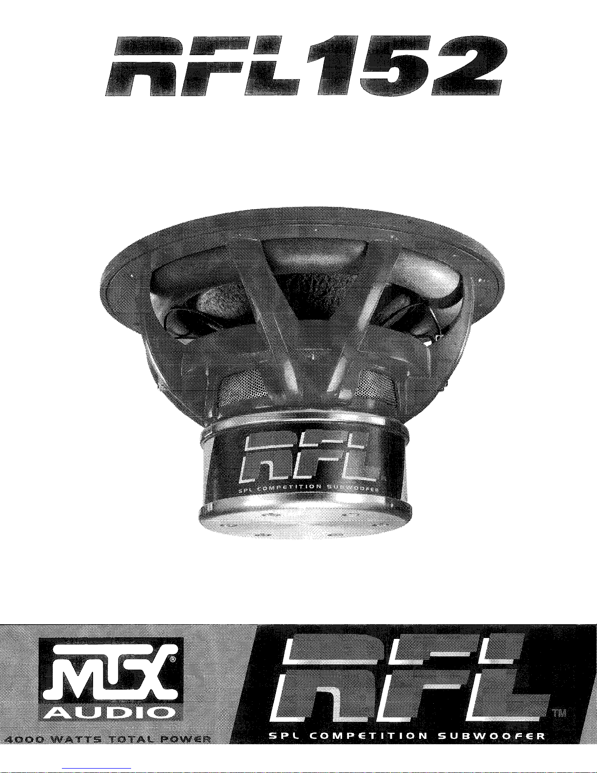
Page 1
Page 2
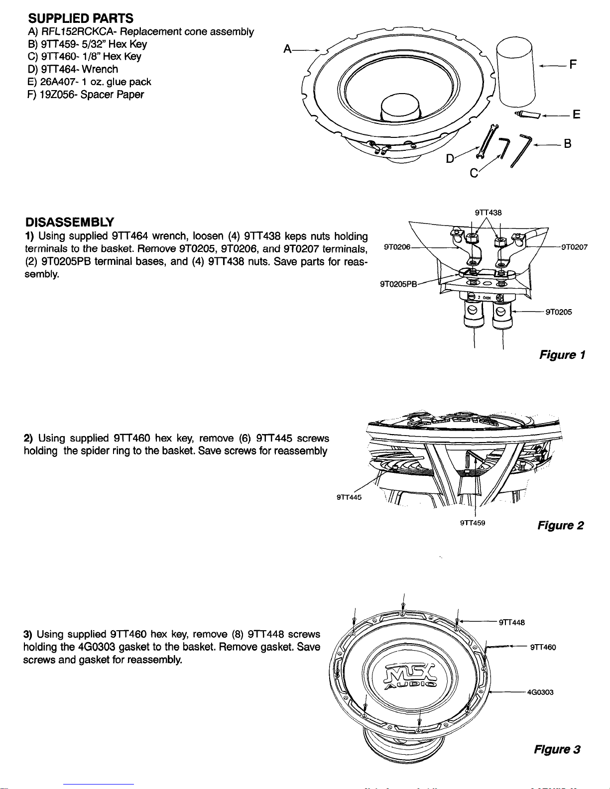
SUPPLIED PARTS
A) RFLi52RCKCA- Replacement cone assembly
B) 9lT459- 5/32” Hex Key
C) 9TT460- l/8” Hex Key
D) 9lT464- Wrench
E) 26A407- 1 oz. glue pack
F) 192056- Spacer Paper
Q-E
DISASSEMBLY
1) Using supplied 9TT464 wrench, loosen (4) 9lT438 keps nuts holding
terminals to the basket. Remove 9TO205, 9T0206, and 9TO207 terminals,
(2) 9T0205PB terminal bases, and (4) 9lT438 nuts. Save parts for reas-
sembly.
Figure 1
2) Using supplied 9lT460 hex key, remove (6) 9lT445 screws
holding the spider ring to the basket. Save screws for reassembly
Figure 2
3) Using supplied 9lT460 hex key, remove (8) 9TT448 screws
holding the 460303 gasket to the basket. Remove gasket. Save
screws and gasket for reassembly.
Figure 3
Page 3

4) Remove cone assembly from woofer. Be careful not to allow anything into the
magnetic gap. If you are not planning to reassemble immediately, tape over the mag-
netic gap for storage.
Figure 4
REASSEMBLY
1) Check magnetic gap of woofer for particles that may interfere with the voice coil. Use tape or other method to remove
anything suspect.
2) Insert new RFL152RCKCA into the woofer. Use supplied 192056 spacer
paper to center the assembly. Be sure to align the tinsel leads from the cone
with the terminals on the basket. Also, align the spider ring holes with the
matching holes on the basket.
192056
Figure 5
3) Insert (6) 9lT445 screws into spider ring and tighten to basket with 9TT459 hex key. NOTE: IT IS VERY IMPORTANT
TO TIGHTEN THE RING DOWN EVENLY Alternate screws, increasing torque by small amounts until all 6 screws are snug.
Refer to Figure 2.
4) Replace 460303 gasket using (8) 9lT448 screws and 9lT460 hex key. Again, it is important to tighten evenly Alternate
screws until the surround is evenly compressed (be careful not to over tighten) between the basket and gasket. Refer to
Figure 3.
5) Remove the 192056 spacer paper. Press down EVENLY on the voice coil to make sure nothing is interfering with the
voice coil movement. If there is interference, than there is either an object in the magnetic gap or the cone assembly was
tightened unevenly. Remove the gasket and cone assembly and go to Step 1 in Reassembly.
Page 4

6) Replace 9TO205,9TO206, and 9TO207 terminals, (2) 9TO205PB terminal bases, and (4) 9lT438 nuts using the supplied 9lT464 wrench.
7) Using the supplied 26A407 glue pack, place an even bead
of glue on the back side of the dust.
7-r
Figure 6
Figure 7
8) MAKE SURE THE 192056 SPACER PAPER HAS BEEN REMOVED. Place the dust cap on the cone body, using the
locator ring as a guide. Make sure to align the logo with the terminals using a ruler or other straight edge. Press down on
the dust cap to evenly spread the glue.
9) Allow the glue to dry for minimum of 1 hour before use.
 Loading...