

MTX MXA4001, MXA8001, MXA6001, MXA3001, MXA4002 Owner's Manual
...

INTRODUCTION
CONGRATULATIONS...
on your purchase of a new Class D Mono block MTX Audio amplifier! MTX is one of the inven
tors of mobile audio, having designed the first-ever in-vehicle enclosed subwoofer system in
the early 80’s. Our award-winning heritage speaks for itself, 14 Innovations Design and Engineering Awards, more than 80 AutoSound Grand Prix Product of the Year Awards, more than
500 World Records or 1st Place Finishes in Sound Competitions. Also, MTX is the first USA
audio Company to be awarded ISO9001 quality assurance certification.. MTX manufacturing
methods are world-class, with more than 1,000,000 square feet of dedicated manufacturing
facilities, using State-of-the-Art Intelligent Surface Mount, Rotational Molding, Robotic Assembly and CNC manufacturing equipment. What all this means to you, the music and audio
fan, is that you couldn’t have chosen a more reliable, powerful, or better performing amplifier.
The Audio Performance Dyno Certificate is your proof. Your amp will meet or exceed its rated
spec, or it doesn’t ship. No compromises, no excuses.
All power ratings are not created equal. CEA 2006 Compliance ensures that the power of
this amplifier is measured according to strict standards dictated by the Consumer Electronics
Association.
We want to ensure you get continuous high performance from your MTX amplifier, so we
recommend that you have it professionally installed by your authorized MTX dealer.
If you are installing this amplifier yourself, we recommend that you read the manual cover-tocover before you install it. Familiarize yourself with the features and details on the input and
output panels. Make sure you have all the equipment you need. Then follow the step-by-step
installation instructions included.
If you have any questions, call us at 800-CALL MTX, or use our live help at
www.mtx.com
MTX Audio
4545 E. Baseline Rd. Phoenix, AZ 85042
602-438-4545 • technical@mtx.com
Please take a moment to register your purchase online at mtx.com. Please also record the
serial number of your amplifier in the space provided below and keep this manual for future
reference, as well as your sales receipt as proof of ownership. (The serial number
of your amplifier is marked on the bottom of its metal chassis.)
Serial Number:
Date of Purchase:

FEATURES
• Patented state-of-the-art power supply
• Patent-pending, Class D technology for high efficiency and
interference-free operation
• High mass extruded aluminum heatsink for maximum thermal management and
bulletproof reliability
• Adjustable LP Crossover - Variable from 40Hz-200Hz for maximum system
design flexibility
• Fully adjustable Bass Boost - 40Hz, 0-18dB to enhance the low frequency
experience in your vehicle
• Remote Subwoofer Level Control included allows you to fine tune the bass from
the driver’s position
• Defeatable Subsonic Filter at 30 Hz for improved efficiency and sonic
performance
• High Level Input with patented Smart Engage Auto Turn-on for easy installation
with factory radios
• CEA 2006 Compliant. All power ratings are not created equal. CEA 2006
Compliance ensures that the power of this amplifier is measured according to
strict standards dictated by the Consumer Electronics Association.
SPECIFICATIONS
2
RMS per channel
@ 4Ω (≤ 1%
THD+N)
150 Watts 200 Watts 300 Watts 400 Watts
RMS per channel
@ 2Ω (≤ 1%
THD+N)
300 Watts 400 Watts 600 Watts 800 Watts
Signal to Noise
Ratio
75 dBA 75 dBA 75 dBA 75 dBA
Frequency
Response
20Hz to 200Hz
(-3dB)
20Hz to 200Hz
(-3dB)
20Hz to 200Hz
(-3dB)
20Hz to 200Hz
(-3dB)
Maximum Input
Signal
5V 5V 5V 5V
Maximum
Sensitivity
100mV 100mV 100mV 100mV
THD+N
(Distortion)
<0.25%
(reference:1W
output)
<0.25%
(reference:1W
output)
<0.25%
(reference:1W
output)
<0.25%
(reference:1W
output)
MXA3001 MXA4001 MXA6001 MXA8001
INSTALLATION
Disconnect the ground at the vehicle battery before proceeding.
1. Connect the amplifier to the battery
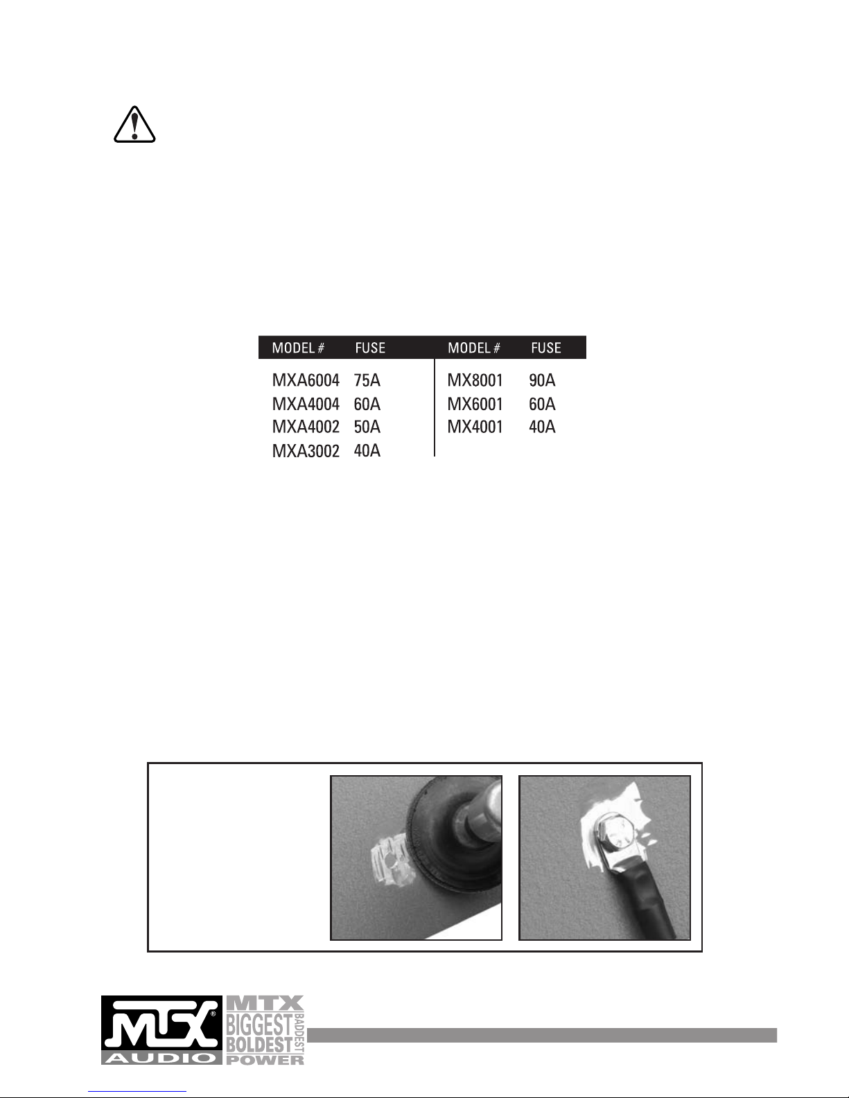
For maximum amplifier performance, we suggest 4 gauge wire and a 1 Farad stiffening
capacitor. A fuse or circuit breaker is required at maximum distance of 18” from the battery to
protect the battery, the vehicle, and more importantly you. (see attached chart for proper fuse
ratings) It is highly recommended that installation be carried out by an authorized MTX dealer
or Circuit City.
2. Connect the amplifier remote turn-on
Connect the remote input terminal of the amplifier to the remote output terminal of the source
unit (only if using RCA inputs) to establish amplifier remote on/off through the power on/off
of the source unit. If the source unit does not provide a remote output, connect to a switched
12-volt source, e.g. ignition switch.
3. Connect the amplifier ground to the vehicle chassis
For maximum amplifier performance we suggest 4 gauge wire. Find a solid piece of metal and
scrape the paint away where the ground will be attached (NO FACTORY BOLTS). Connect the
ground cable to the amplifier at this point.
- NOTE -
For optimum performance
and sound reproduction,
prepare and secure the
ground properly. Remove
any surface material before
securing to your chassis,
ensuring a metal-to-metal
ground point.
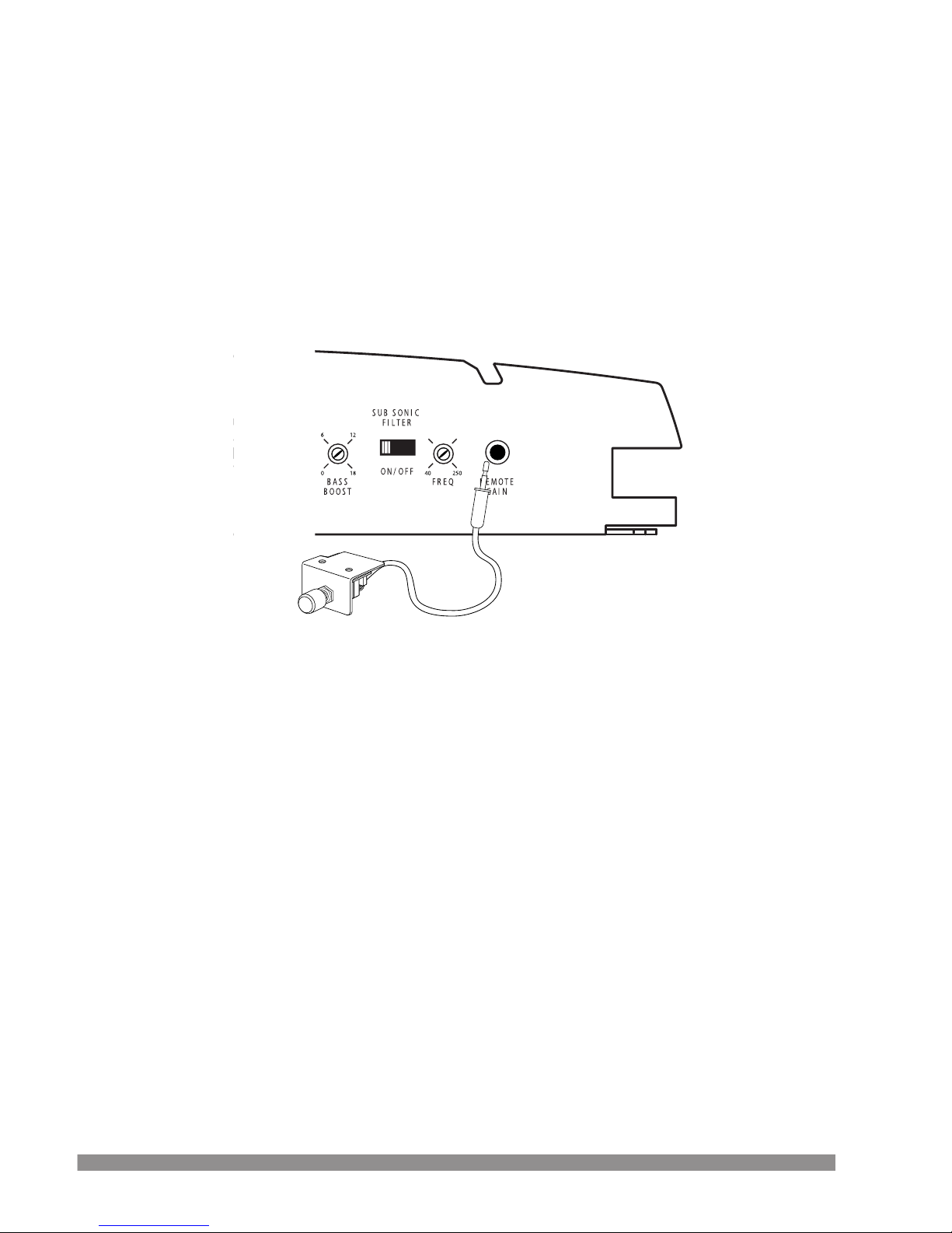
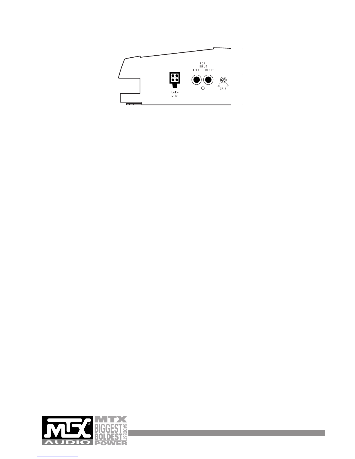
4. Remote Gain Control
Included is a remote gain control, which is a volume control that is active with the low pass
filter engaged. This control should be mounted near the driver in an easily accessed location.
This is not a gain knob, this is a level control. The level control will attenuate the amp or
increase its output to the level of the gain setting. It is used to adjust bass output between
music sources or tracks (see picture below for connection location).
5. Connecting signal cables to the amplifier
There are two ways to supply the signal to our amplifiers. To get maximum performance, we
suggest connecting a high quality RCA to the corresponding outputs at the source unit and
inputs of the amplifier. If a source unit is being used without RCA outputs, use the high-level
inputs for signal which will turn the amplifier on via our Smart Engage circuitry (Four-channel
amps will only engage on the front high-level inputs).
6. Reconnect the battery ground to the vehicle battery
Double check all the previous installation steps. Make certain the wiring and component connections are securely attached to the amp +BATT, remote and ground. If everything is in order,
complete the installation by reconnecting the battery ground to the vehicle battery.
4
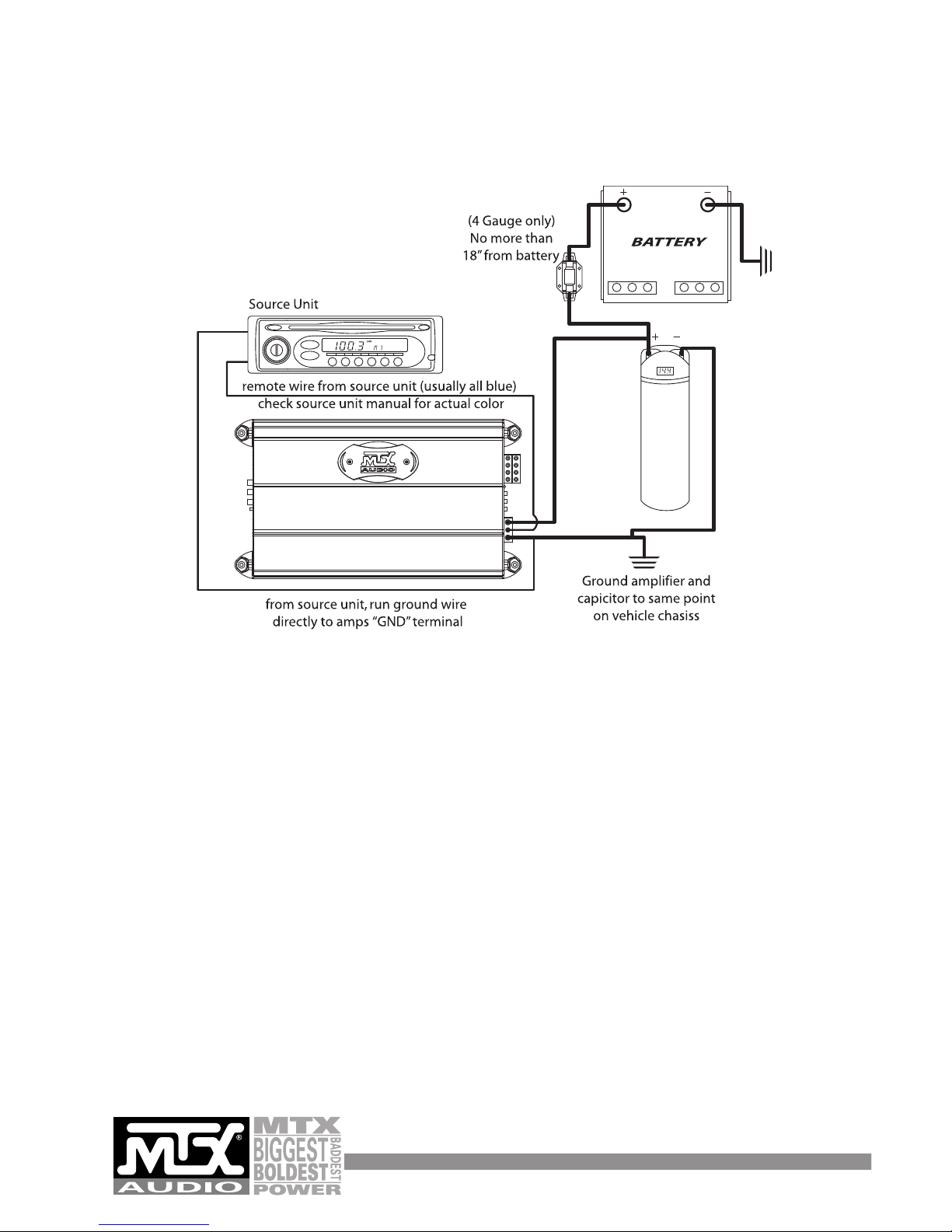
WIRING DIAGRAM (CHARGING SYSTEM)
1 Farad
Stiffening
Capicitor

WIRING DIAGRAM (5.1 SURROUND SOUND EXAMPLE)
6
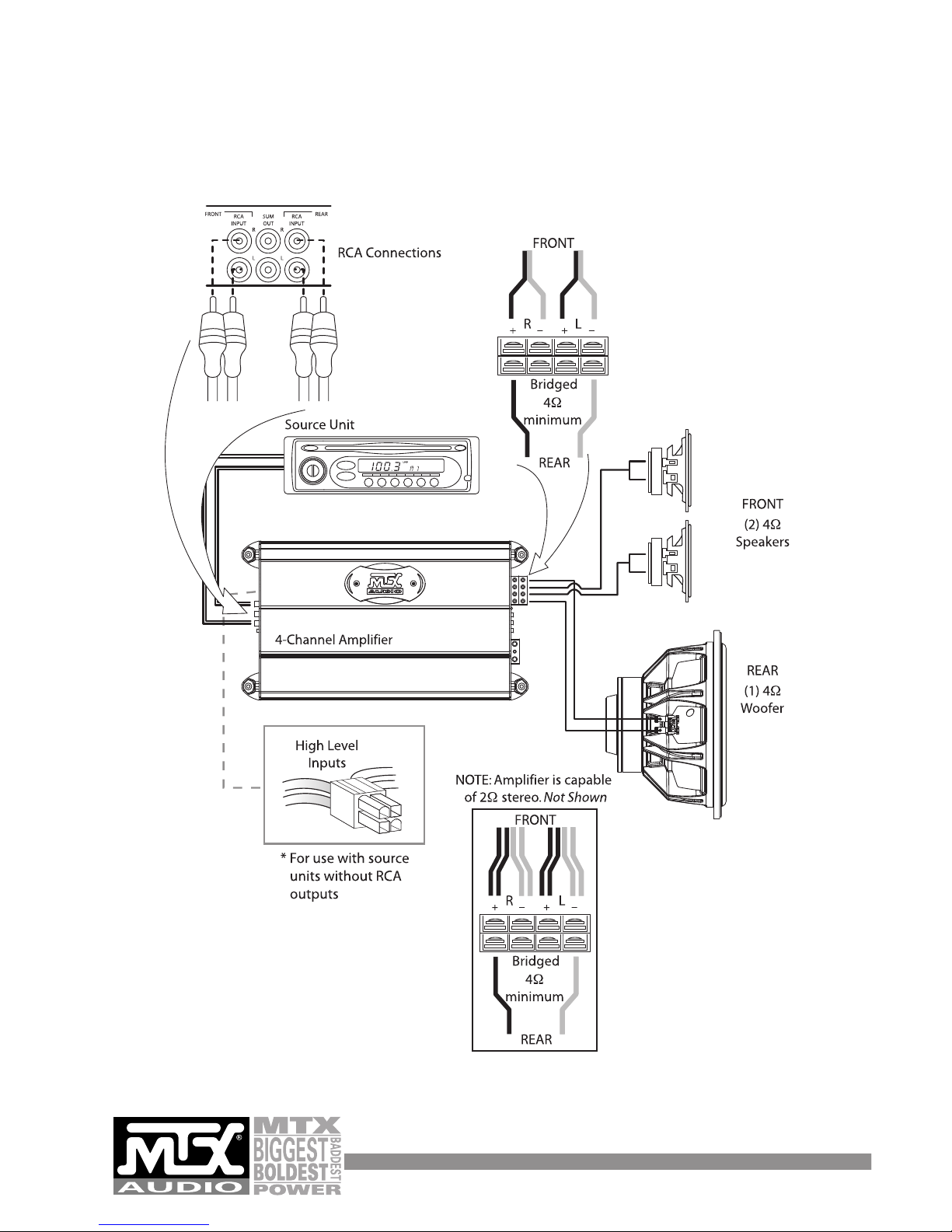
WIRING DIAGRAM (SINGLE 4-CHANNEL AMPLIFIER SYSTEM)
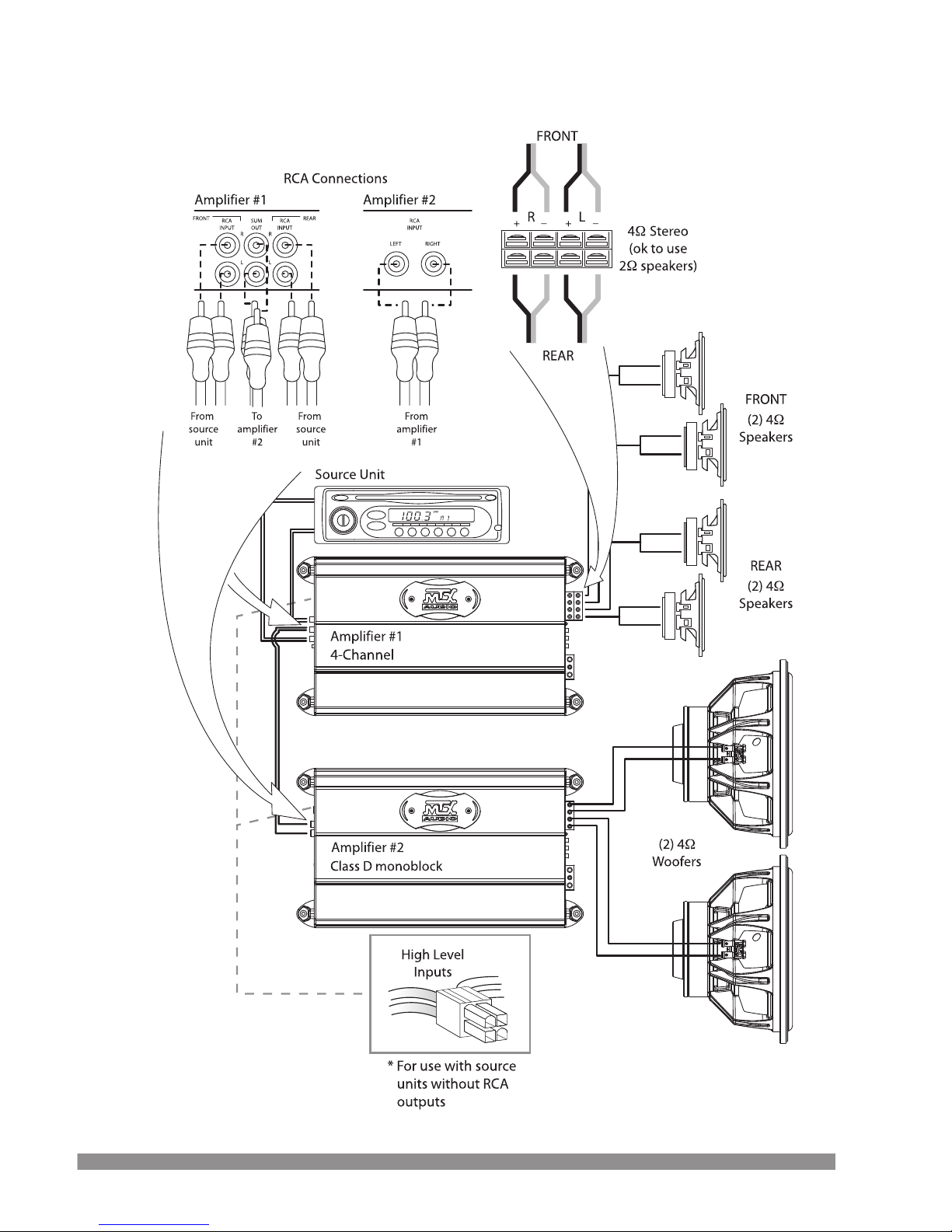
WIRING DIAGRAM (MULTI AMPLIFIER SYSTEM)
8
Located on the Input Panel, the objective of GAIN adjustment is to match the output of the
source unit with the input of the amplifier. The output voltage of individual source units can
vary. Some source units have an output of 200 mV and others have 5 Volts or more. To cater
to these variations, the amplifier has an adjustable gain control that ranges from 100 mV to
5 volts. Adjusting this control requires some experimenting to ensure all of the gain is at the
beginning of the system, NOT at the end (amplifier). Turn your source unit up and keep your
amplifier gains at the lowest possible setting (counter-clockwise) with the maximum output.
This will give you the best sound and signal-to-noise ratio.
Besides better sonic reproduction, proper input GAIN also helps to prolong the reliability span
of your amplifier by eliminating excessive internal temperature generated by
incompatible source unit output and amplifier input.
Note : Turning the input gain up does not indicate more power. Just more noise. The input
gain control is not a power control.
If the Remote Gain is used, connect the plug of the Remote Gain to the port on the panel of
the amplifier.
1. Turn the input GAIN all the way down (counter clockwise).
2. Set the volume control of the source unit to approximately 3/4 of its maximum output.
3. Turn the balance control of the source unit to its center position (flat).
4. Leave the tone (bass/treble) controls at their usual position (flat).
5. Play a CD or tape track with great dynamic range.
6. Use the Bass Boost Control on the amp to enhance the bass performance (if desired),
not the bass on the headunit. Use this control sparingly.
7. To locate the optimum gain setting, ask the person assisting you to turn the input GAIN
control clockwise until audio distortion starts to develop. Turn the gain control back
wards slightly to minimize the distortion.
8. If you constantly switch between CD/tape and radio, you will need further adjustment
since radio output level differs from that of CD or tape. In this case, you need to locate
a balanced gain setting which is best for both the output level of radio and that of
CD or tape
SYSTEM TUNING (INPUT GAIN ADJUSTMENT)
 Loading...