

Page 1
USERGUIDE
HARDWARE
MTX-xG-JAVA-IoT
SMART SOLUTIONS FOR A CHANGING WORLD
#WeAreConnectivity
www.mtxm2m.com
Page 2

2
MTX-Java-IoT | 2018/2
MTX © by MATRIX ELECTRONICA S.L.U.
SUPPORT: iotsupport@mtxm2m.com | SALES: info@mtxm2m.com | mtxm2m.com
Index
GENERAL NOTES ....................................................................................................................6
IMPORTANT INFORMATION ................................................................................................... 6
SERVICE AND SUPPORT ........................................................................................................ 6
REVISION INFORMATION ....................................................................................................... 7
INTRODUCTION .......................................................................................................................8
1. Description ................................................................................................................................................8
2. Ordering Information ................................................................................................................................9
3. Features by Model ....................................................................................................................................10
4. Compatibility Table ...................................................................................................................................11
5. Highlights...................................................................................................................................................12
6. Product Label ............................................................................................................................................14
7. Main Features and Services .....................................................................................................................15
7.1 Key features at a glance...............................................................................................................15
The MTX-4G-Java is a LTE bands mobile station with the characteristics shown in the table below.
17
7.2 Operating modes ..........................................................................................................................21
7.3 Power consumption ......................................................................................................................23
7.4 RF antenna interface description ................................................................................................25
7.5 SIM card ........................................................................................................................................34
8. Precautions ...............................................................................................................................................35
9. Block Diagram ...........................................................................................................................................36
9.1 Models with Power Relay 220VAC/6A ........................................................................................36
9.2 Models with RJ11 connector and/or analog audio ...................................................................37
9.3 Models with 5-way terminal block ...............................................................................................38
10. Hardware Revisions ................................................................................................................................39
MECHANICAL DESCRIPTION ................................................................................................. 40
1. Overview ....................................................................................................................................................40
1.1 Models with 5-way plug-in 5.00mm pitch terminal block ..........................................................40
1.2 Models with RJ11 connector .......................................................................................................41
2. Dimensions (mm) .....................................................................................................................................42
Page 3

3
MTX-Java-IoT | 2018/2
MTX © by MATRIX ELECTRONICA S.L.U.
SUPPORT: iotsupport@mtxm2m.com | SALES: info@mtxm2m.com | mtxm2m.com
ELECTRICAL AND ENVIRONMENTAL CHARACTERISTICS ..................................................43
1. Electrical specications ............................................................................................................................43
1.1 Power supply .................................................................................................................................43
1.2 RS232 interface ...........................................................................................................................44
1.3 RS485 interface ...........................................................................................................................45
1.4 Counter input ................................................................................................................................46
1.5 Optoisolated input/output ...........................................................................................................46
1.6 Analog input/output .....................................................................................................................48
1.7 1-wire (by request) .......................................................................................................................49
1.8 Power relay ...................................................................................................................................49
1.9 Latch relay ....................................................................................................................................50
2. Operating Temperatures ..........................................................................................................................51
3. Storage Conditions ...................................................................................................................................52
INTERFACE DESCRIPTION .....................................................................................................53
1. Power Supply Connector ..........................................................................................................................54
1.1 Models with Power Relay 220V/6A (5-way plug-in 5.00mm pitch terminal block) ..................54
1.2 Models with RJ11 connector .......................................................................................................55
1.3 All other models (5-way plug-in 5.00mm pitch terminal block) ................................................56
2. Micro USB Connector ...............................................................................................................................57
3. DB9 Connector: 8-wire RS232.................................................................................................................58
4. DB15 HD Connector: I/O expansion port ................................................................................................60
4.1 Connector pinout ..........................................................................................................................60
4.2 RS232 ...........................................................................................................................................62
4.3 Analog inputs ................................................................................................................................63
4.4 Optoisolated I/O ...........................................................................................................................63
4.5 Counter input ................................................................................................................................64
5. RS485 bus ................................................................................................................................................65
6. DIP switches ..............................................................................................................................................66
7. Relays .........................................................................................................................................................67
8. Analog audio interface .............................................................................................................................68
9. GSM/GPRS/UMTS ANtenna Connector ..................................................................................................71
10. SIM Card Reader ....................................................................................................................................72
Page 4

4
MTX-Java-IoT | 2018/2
MTX © by MATRIX ELECTRONICA S.L.U.
SUPPORT: iotsupport@mtxm2m.com | SALES: info@mtxm2m.com | mtxm2m.com
11. Internal Li-Po Battery ..............................................................................................................................73
12. Real Time Clock ......................................................................................................................................76
13. GPS ..........................................................................................................................................................77
13.1 GPS antenna connector.............................................................................................................77
13.2 GPS application interface..........................................................................................................77
13.3 GPS antenna interface characteristics.....................................................................................77
14. Internal Modules .....................................................................................................................................79
14.1 Bluetooth 2.1 ..............................................................................................................................79
14.2 Bluetooth Low Energy (4.0) .......................................................................................................79
14.3 Coronis Wavecard 25/500mW .................................................................................................79
15. Firmware Updates .................................................................................................................................80
OPERATION .............................................................................................................................. 81
1. Switching on the modem. New “Automatic restart after shutdown” feature ........................................81
2. Power Modes .............................................................................................................................................82
2.1 Ultra Low Power mode .................................................................................................................82
2.2 Low Power mode ..........................................................................................................................82
3. Status LEDs ...............................................................................................................................................83
EMBEDDED APPLICATIONS ................................................................................................... 85
1. MTX-Tunnel Software Application ............................................................................................................87
SAFETY AND PRODUCT CARE ............................................................................................... 89
1. Safety Instructions ....................................................................................................................................89
2. General Precautions .................................................................................................................................90
3. SIM Card Precautions ...............................................................................................................................91
4. Antenna Precautions ................................................................................................................................92
5. Radio Frequency (RF) Exposure and SAR ...............................................................................................93
6. Personal Medical Devices ........................................................................................................................94
MODEM INSTALLATION .......................................................................................................... 95
1. Where to Install the Modem .....................................................................................................................95
1.1 Environmental conditions ............................................................................................................95
1.2 Signal strength .............................................................................................................................95
1.3 Connections of components to MTX-Java-IoT device .................................................................95
1.4 Network and subscription ............................................................................................................95
Page 5

5
MTX-Java-IoT | 2018/2
MTX © by MATRIX ELECTRONICA S.L.U.
SUPPORT: iotsupport@mtxm2m.com | SALES: info@mtxm2m.com | mtxm2m.com
2. How to Install the Modem ........................................................................................................................96
2.1 Power supply .................................................................................................................................96
2.2 Securing the modem ...................................................................................................................96
3. Antenna .....................................................................................................................................................97
3.1 General .........................................................................................................................................97
3.2 Antenna type ................................................................................................................................97
3.3 Antenna placement ......................................................................................................................97
3.4 The antenna cable .......................................................................................................................98
3.5 Possible communications disturbances .....................................................................................98
CONFORMITY ASSESSMENT ................................................................................................. 99
1. RED Declaration of Conformity ................................................................................................................99
2. FCC Compliant ..........................................................................................................................................100
2.1 SAR information ...........................................................................................................................100
DECLARACIÓN DE CONFORMIDAD ...................................................................................... 102
1. Declaración de conformidad RED............................................................................................................102
2. Conformidad FCC ......................................................................................................................................103
2.1 Tasa de absorción especíca (SAR) ............................................................................................103
REGULATORY AND TYPE APPROVAL INFORMATION ......................................................... 105
1. Directives and Standards .........................................................................................................................105
2. SAR Requirements Specic to Portable Mobiles ....................................................................................108
3. SELV Requirements ..................................................................................................................................109
ROHS STATEMENT ..................................................................................................................110
DISPOSAL OF OLD ELECTRICAL AND ELECTRONIC EQUIPMENT ....................................111
ABBREVIATIONS ...................................................................................................................... 112
AT COMMAND SUMMARY ......................................................................................................118
ACCESSORIES .........................................................................................................................127
SALES CONTACT ......................................................................................................................128
Page 6

6
MTX-Java-IoT | 2018/2
MTX © by MATRIX ELECTRONICA S.L.U.
SUPPORT: iotsupport@mtxm2m.com | SALES: info@mtxm2m.com | mtxm2m.com
GENERAL NOTES
Product is deemed accepted by recipient and is provided without interface to recipient’s products. The
documentation and/or product are provided for testing, evaluation, integration and information purposes.
The documentation and/or product are provided on an “as is” basis only and may contain deciencies or
inadequacies. The documentation and/or product are provided without warranty of any kind, express or
implied. To the maximum extent permitted by applicable law, Matrix Electronica S.L.U. further disclaims all
warranties; including without limitation any implied warranties of merchantability, completeness, tness
for a particular purpose and non-infringement of third-party rights. The entire risk arising out of the use or
performance of the product and documentation remains with recipient. This product is not intended for
use in life support appliances, devices or systems where a malfunction of the product can reasonably be
expected to result in personal injury. Applications incorporating the described product must be designed
to be in accordance with the technical specications provided in these guidelines. Failure to comply with
any of the required procedures can result in malfunctions or serious discrepancies in results.
Furthermore, all safety instructions regarding the use of mobile technical systems, including GSM
products, which also apply to cellular phones, must be followed. Matrix Electronica S.L.U. or its suppliers
shall, regardless of any legal theory upon which the claim is based, not be liable for any consequential,
incidental, direct, indirect, punitive or other damages whatsoever (including, without limitation, damages
for loss of business prots, business interruption, loss of business information or data, or other pecuniary
loss) arising out the use of or inability to use the documentation and/or product, even if Matrix Electronica
S.L.U. has been advised of the possibility of such damages. The foregoing limitations of liability shall not
apply in case of mandatory liability, e.g. under the Spanish Product Liability Act, in case of intent, gross
negligence, injury of life, body or health, or breach of a condition which goes to the root of the contract.
However, claims for damages arising from a breach of a condition, which goes to the root of the contract,
shall be limited to the foreseeable damage, which is intrinsic to the contract, unless caused by intent or
gross negligence or based on liability for injury of life, body or health. The above provision does not imply
a change on the burden of proof to the detriment of the recipient. Subject to change without notice at
any time. The interpretation of this general note shall be governed and construed according to Spanish
law without reference to any other substantive law.
IMPORTANT INFORMATION
This technical description contains important information for the startup and use of the MTX-Java-IoT
modem. Read it carefully before you start working with the MTX-Java-IoT device. The warranty will be
void should damage occur due to non-compliance with these instructions for use. We cannot accept any
responsibility for consequential loss.
SERVICE AND SUPPORT
To contact customer support please contact your local distributor/sales agent or use the details below:
Address: Alejandro Sánchez 109, 28019 Madrid (Spain)
Email: gsmsupport@matrix.es
Website: mtxm2m.com
Page 7

7
MTX-Java-IoT | 2018/2
MTX © by MATRIX ELECTRONICA S.L.U.
SUPPORT: iotsupport@mtxm2m.com | SALES: info@mtxm2m.com | mtxm2m.com
REVISION INFORMATION
REVISION DATE AUTHOR CHANGES
1.0 2016/01 AEM Initial release
1.1 2017/05 JS Approvals-RED
1.2 2017/07 SJ Added LTE versions
Page 8

8
MTX-Java-IoT | 2018/2
MTX © by MATRIX ELECTRONICA S.L.U.
SUPPORT: iotsupport@mtxm2m.com | SALES: info@mtxm2m.com | mtxm2m.com
INTRODUCTION
1. Description
The MTX-Java-IoT devices are an innovative and powerful all-in-one solution for the most demanding
M2M and Internet of Things applications, enabling GSM data & voice communication, SMS, fax and
2G/3G/4G high speed cellular data transmission.
The MTX-Java-IoT modems are Java J2ME programmable and have a complete set of interfaces (RS232,
RS485, USB, I2C, optoisolated IOs and Analog-to-Digital converter) avoiding need for further hardware
components, shortening time to market and reducing costs. It also has a modular architecture allowing
a series of optional features:
• GPS module inside: allows track & location applications
• RF card: up to 2x wireless modules (Wavenis, Bluetooth, ZigBee, ISM 868/915, LORA, Sigfox,…)
• Internal Li-Po Battery
• Ultra Low Power: 2.5µA power consumption in sleep mode. Ideal in remote-battery operated
systems
• Relay: latch relay or 220VAC/6A relay options are available
• Analog audio: enabling voice applications
Please read section Introduction 3 (Features by Model) to view the specic features of each device.
The MTX-Java-IoT family is industrially featured: the unit can be used in industrial environments due to its
extended operating temperature range. It also features an automatic restart after shutdown function in
case of power glitches or faulty conditions.
The MTX-Java-IoT are a self-contained modems with its own SIM card holder, USB 2.0 High Speed and
RS232/485 interfaces (among others), which minimize the need for further hardware development. This
device can be used as a powerful and exible device that can be integrated in a wide range of telemetry
applications that rely on the remote exchange of data, SMS or faxes via the GSM cellular network.
The ve-band functionality allows for operation in all relevant GSM frequencies across the world. Local
European and America economic variants are available. When UMTS/3G network operation is not
present, the MTX-Java-IoT can operate in lower speed modes such EDGE Class 12 (max. 237kbps DL,
max. 237kbps UL) or GPRS Class 12 (max. 85.6kbps DL, max. 85.6kbps).
The MTX-Java-IoT devices can also be controlled via AT commands and standard interfaces such us USB
2.0 High Speed or RS232 with Linux and Windows® drivers.
The MTX-Java-IoT family is RoHS & WEEE compliant and it is manufactured following the ISO 9001 & IS0
14001 Quality certications.
A full list of antennas, cables and accessory supplies are available.
The MTX-Java-IoT modems are powered by an internal EHS6/8/BGS5/ELS6/5 modules.
Page 9
9
MTX-Java-IoT | 2018/2
MTX © by MATRIX ELECTRONICA S.L.U.
SUPPORT: iotsupport@mtxm2m.com | SALES: info@mtxm2m.com | mtxm2m.com
2. Ordering Information
Variants
STANDARD MODELS:
STD: both DB9 and DB15 connectors are
available
LC: neither DB9 nor DB15 connectors are
available
CUSTOM MODELS:
DB15: only connector available DB15
DB9: only connector available DB9
MTX - xG - JAVA - IoT - Variant - Options - Wireless
xG
3G module: 3G/2G
4G module: 4G/3G/2G
Wireless Modules
BT: Bluetooth 2.1
BLE: Bluetooth low energy
WC868: wavecard 25mW 868MHz
WC868-LR: wavecard 500mW 868MHz
WC915: wavecard 25mW 915MHz
WC915-LR: wavecard 500mW 915MHz
WMBUS: WMBUS module (TBD)
GPS: GPS/Glonass (-165dBm)
ACCEL: 3-axis accelerometer
Note: if using 2 modules, the RS232 (8-wire) port
(DB9) will not be available anymore.
Options
N: no options
A: analog audio
B: internal Li-Po battery (1650mAh)
G: GPS internal EHS8
S: SuperCap
V: Very Low Power controller (up to 100µA)
Note: not all options are available at the same time.
Page 10
10
MTX-Java-IoT | 2018/2
MTX © by MATRIX ELECTRONICA S.L.U.
SUPPORT: iotsupport@mtxm2m.com | SALES: info@mtxm2m.com | mtxm2m.com
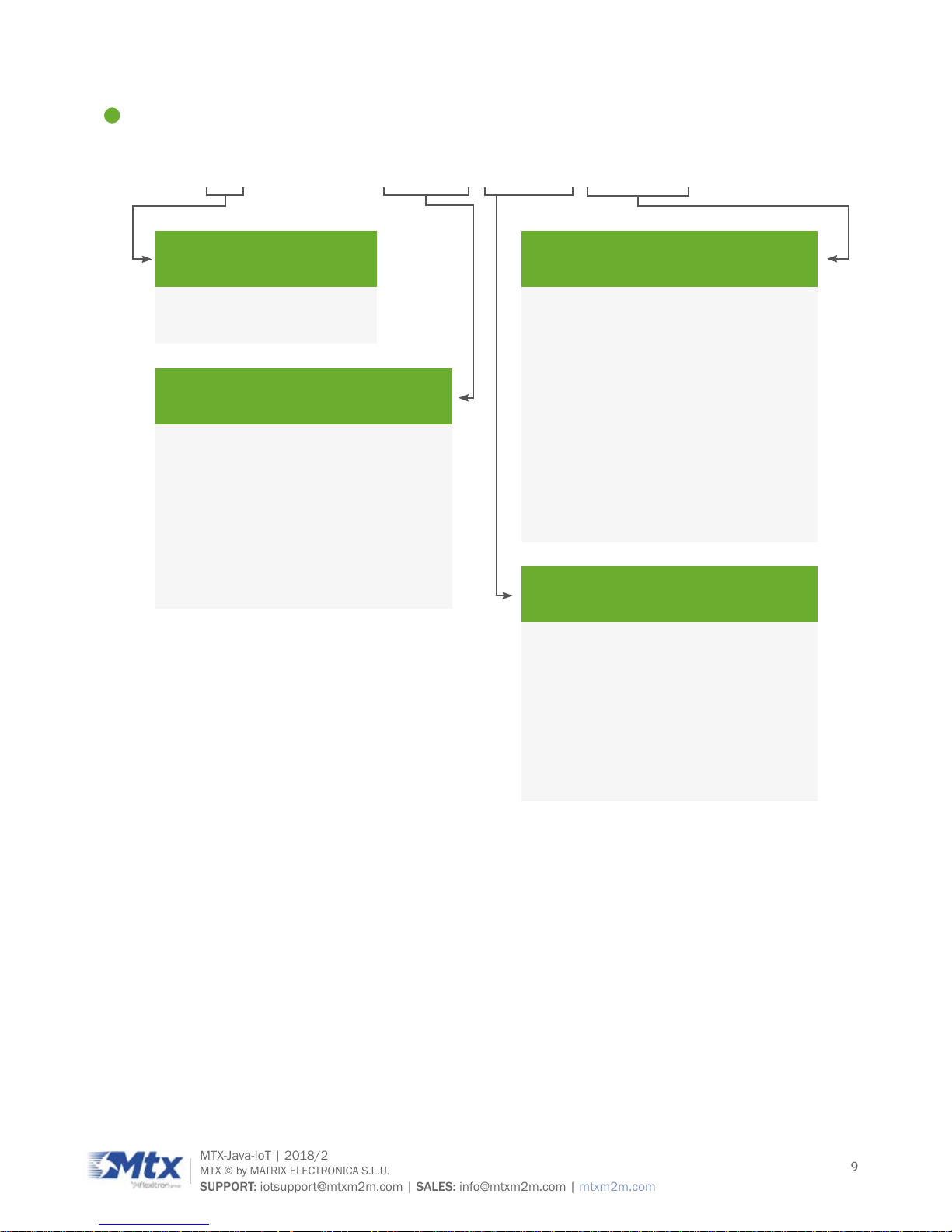
3. Features by Model
MTX-xG-JAVA-IoT
STANDARD VERSIONS CUSTOM VERSIONS (by request only)
-STD -LC -DB15 -DB9
GPS
*
* * *
RS232 (8-wire)
X
X
RS232 (4-wire)
X X
RS485
X
X X X
USB
X
X X X
ADC
x2
x2
Optoisolated IO
x4
x4
Counter input
x3
x3
Analog Audio (A)
(*1)
(*1) (*1) (*1)
Li-Po battery (B)
(*1)
(*1) (*1) (*1)
SuperCap (S)
(*1)
(*1) (*1) (*1)
Very Low Power (V)
(*1)
(*1) (*1) (*1)
Internal wireless module
(*1)
(*1) (*1) (*1)
* Optional
(*1): option. See incompatibility table
Page 11
11
MTX-Java-IoT | 2018/2
MTX © by MATRIX ELECTRONICA S.L.U.
SUPPORT: iotsupport@mtxm2m.com | SALES: info@mtxm2m.com | mtxm2m.com
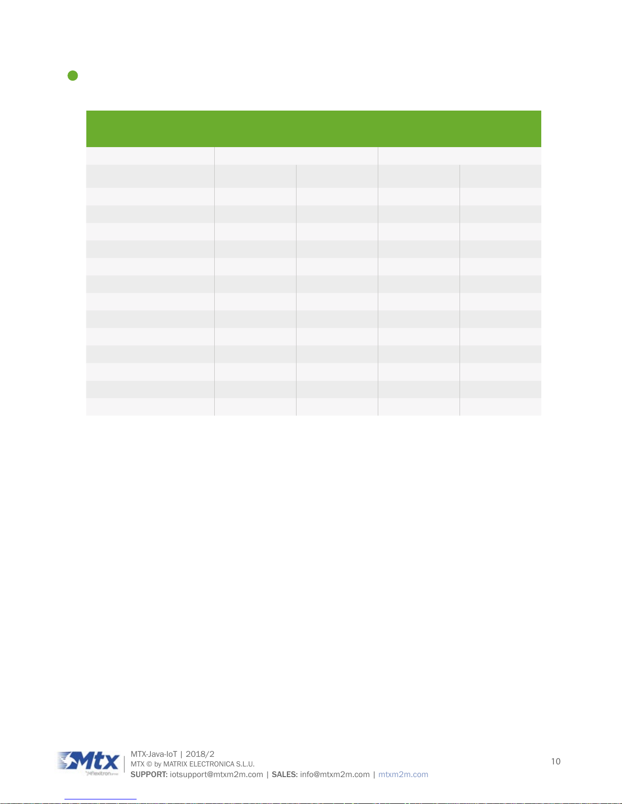
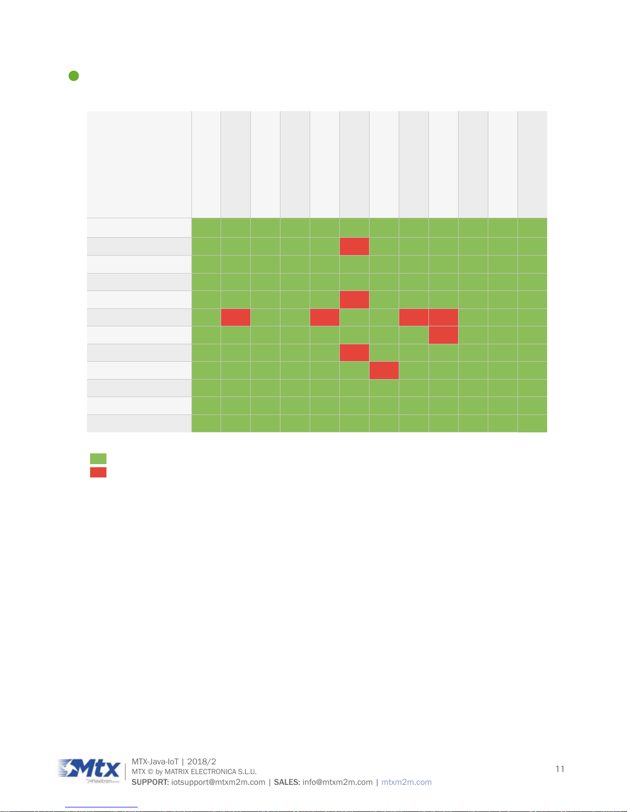
4. Compatibility Table
3G (3G/2G)
4G (4G/3G/2G)
RS232 (8-wire) DB9
RS232 (4-wire) DB15
RS485
-A (Analog audio)
-B (Li-Po battery)
-G (GPS internal EHS8)
-S (SuperCap)
-V (Very Low Power)
Wireless module
GPS module
3G (3G/2G)
4G (4G/3G/2G)
RS232 (8-wire) DB9
(*1)
RS232 (4-wire) DB15
(*1)
RS485
(*1)
-A (Analog audio)
-B (Li-Po battery)
-G (GPS internal EHS8)
-S (SuperCap)
-V (Very Low Power)
Wireless module
(*1) (*1) (*1)
GPS module
(*1): all serial ports not available at the same time
Compatible
Non-compatible
Page 12
12
MTX-Java-IoT | 2018/2
MTX © by MATRIX ELECTRONICA S.L.U.
SUPPORT: iotsupport@mtxm2m.com | SALES: info@mtxm2m.com | mtxm2m.com
5. Highlights
MTX-4G-JAVA-IoT Family MTX-3G-JAVA-IoT Family
EU: LTE 4bands (800, 900, 1800, 2100MHz),
GSM/GPRS/EDGE: 2bands (900, 1800MHz)
US: LTE 4bands (700, 850, 1700, 2100 (AWS),
1900MHz), 3bands UMTS (WCDMA/FDD 850,
1700/2100 (AWS), 1900 MHz)
UMTS/HSPA+: 5bands (800, 850, 900, 1900,
2100MHz), GSM/GPRS/EDGE: 4bands (850,
900, 1800, 1900MHz)
4G
LTE Cat.1: DL 10.2Mbps, UL 5.2Mbps
3G
HSPA+ Cat.8: data rates DL
7.2Mbps, UL 5.76Mbps
HSPA (3GPP release 6,7): DL 7.2Mbps, UL
5.7Mbps; HSDPA Cat.8/HSUPA Cat.6
UMTS (3GPP release 4): PS data
rate 384 kbps DL, UL 384kbps
2G
GPRS (EU only): DL 85.6kbps, UL 85.6kbps EGPRS: multislot class 12; EDGE
E2 power class for 8PSK
GPRS class 12; mobile station
class B; PBCCH support
CSD
CSD data transmission up to 9.6
kbps, V.110, non-transparent
SMS
SMS: text and PDU
mode support
SMS: point-to-point MO and
MT; text and PDU mode
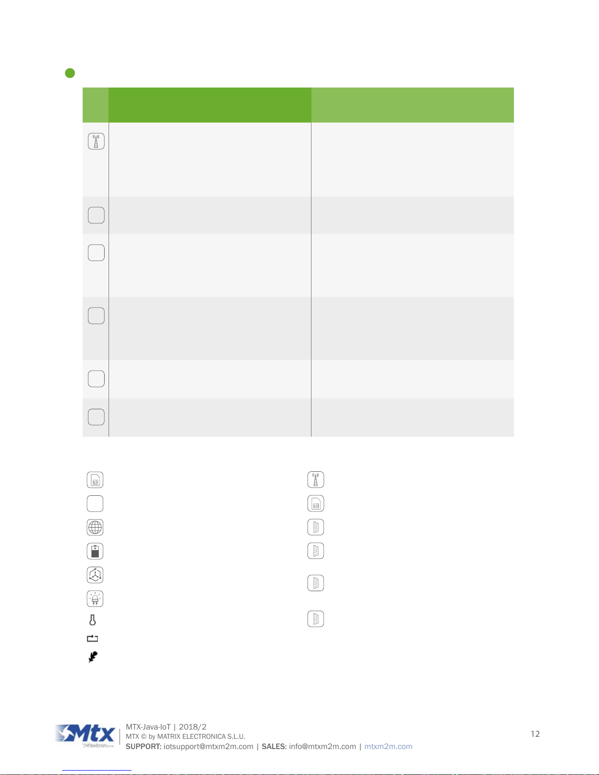
General Features
SIM application toolkit, 3GPP release 99
>_
Control and TCP/IP stacks access via AT
commands
Internet services: TCP, UDP, HTTP, FTP, SMTP,
POP3
+
Internal 1650mAh Li-Po battery*
3-axis accelerometer*
Operating status LEDs
Temperature range: -30º to +85ºC
Dimensions: 78.1x66.8x37.2mm
Weight: <190gr
Interfaces
GSM FME M and SMA F antenna connector
or other RF options*
SIM card interface 1.8V and 3V
DB9 female connector
HD-DB15 female connector: RS232 (4-wire),
3x inputs (2x otpo), 2x opto outputs, 2x
analog inputs
5-way plug-in: RS485, power supply input;
7-way plug-in: latch relay ;
5-way plug-in: 200VAC/6A relay
2x RJ11 connectors*
* Depending on model, see features by model table
Page 13

13
MTX-Java-IoT | 2018/2
MTX © by MATRIX ELECTRONICA S.L.U.
SUPPORT: iotsupport@mtxm2m.com | SALES: info@mtxm2m.com | mtxm2m.com
Special Features
USB interfaces support composite modes
and Linux/Mac compliant mode
Firmware update via USB/RS232
Real Time Clock with alarm functionality
Multiplexer according 3GPP TS 27.010
RLS monitoring and informal network scan
Java Features
Oracle Java ME embedded 3.2
Compliant to CLDC 1.1 HI and IMP-NG
standards
Capable of running multiple MIDIets in
parallel with inter-MIDIet communication
Java standard APIs: JSR75 (FileConnection),
JSR177 (CRYPTO), JSR280 (XML)
Accessible periphery for Java applications
Memory space for Java applications
Page 14
14
MTX-Java-IoT | 2018/2
MTX © by MATRIX ELECTRONICA S.L.U.
SUPPORT: iotsupport@mtxm2m.com | SALES: info@mtxm2m.com | mtxm2m.com
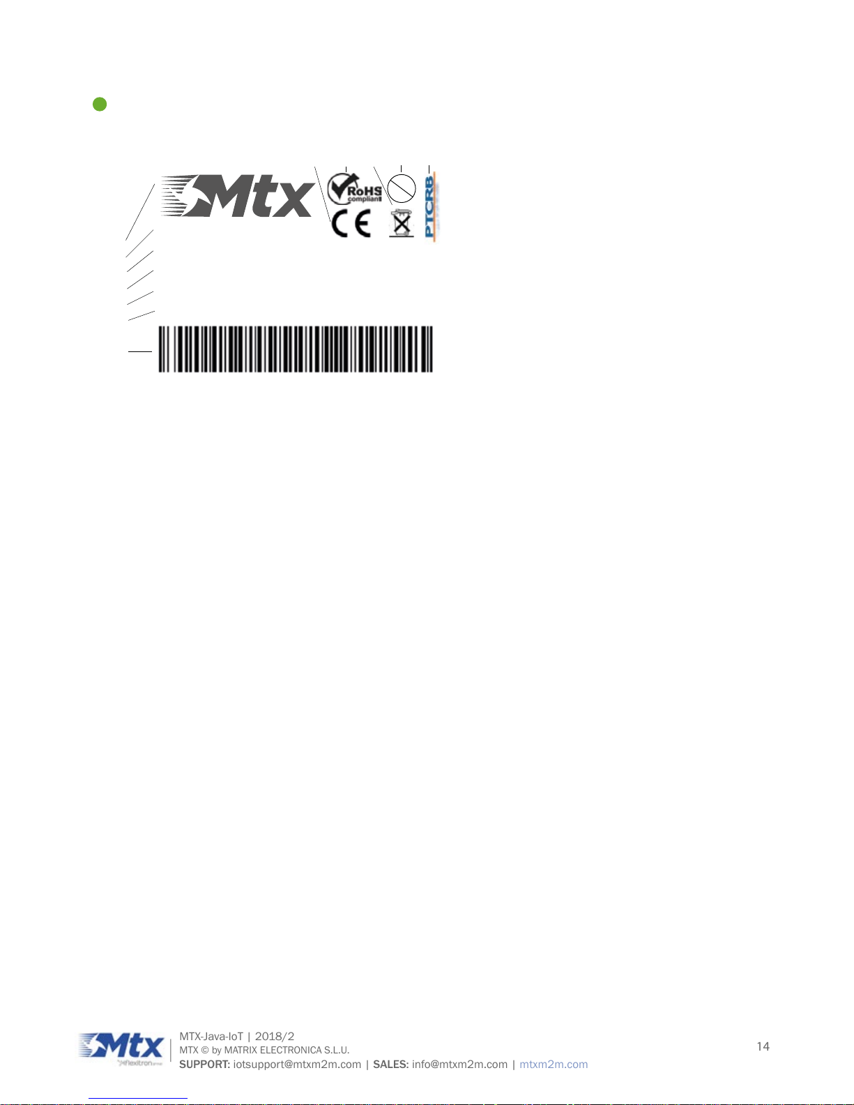
6. Product Label
Pb
P/N:123456789
MTX-MODEL-NAME
HR: 0.00 FW: 0.000
containsFCC ID:XX
18xx IMEI:012345678912345
1
2
3
4
5
6
7
8910 11 12
1. MTX logo
2. Part number/ordering code
3. Product name (model)
4. Hardware and rmware versions
5. FCC ID
6. Year/week of fabrication
7. Barcode (code 128) (IMEI)
8. CE logo
9. RoHS symbol
10. WEEE symbol
11. Pb-free symbol
12. PTCRB certication logo
Page 15

15
MTX-Java-IoT | 2018/2
MTX © by MATRIX ELECTRONICA S.L.U.
SUPPORT: iotsupport@mtxm2m.com | SALES: info@mtxm2m.com | mtxm2m.com
7. Main Features and Services
The MTX-Java-IoT performs a set of telecom services (TS) according to GSM standard phase 2+, ETSI and
ITU-T. The services and functions of the MTX-3G-Java are implemented by issuing customized applications
embedded on the device, by AT commands issued internally or over the USB, RS232 or RS485 interface.
7.1 Key features at a glance
The MTX-3G-Java is a UMTS/HSPA and also GSM/GPRS/EDGE bands mobile station with the
characteristics shown in the table below.
FEATURE IMPLEMENTATION
General
Frequency bands UMTS/HSPA+: Five band, 800/850/900/1900/2100MHz
GSM/GPRS/EDGE: Quad band, 850/900/1800/1900MHz
GSM class Small MS
Output power Class 4 (+33dBm ±2dB) for EGSM850
Class 4 (+33dBm ±2dB) for EGSM900
Class 1 (+30dBm ±2dB) for GSM1800
Class 1 (+30dBm ±2dB) for GSM1900
Class E2 (+27dBm ± 3dB) for GSM 850 8-PSK
Class E2 (+27dBm ± 3dB) for GSM 900 8-PSK
Class E2 (+27dBm +3dB/-4dB) for GSM 1800 8-PSK
Class E2 (+27dBm +3/-4dB) for GSM 1900 8-PSK
Class E2 (+26dBm +3/-4dB) for GSM 1800 8-PSK
Class 3 (+24dBm +1/-3dB) for UMTS 2100, WCDMA FDD BdI
Class 3 (+24dBm +1/-3dB) for UMTS 1900, WCDMA FDD BdII
Class 3 (+24dBm +1/-3dB) for UMTS 900, WCDMA FDD BdVIII
Class 3 (+24dBm +1/-3dB) for UMTS 850, WCDMA FDD BdV
Class 3 (+24dBm +1/-3dB) for UMTS 800, WCDMA FDD BdVI
Power supply Single supply voltage
Maximum: 6.5 to 40V (without damaging the device)*
Recommended: 7 to 35V
*(Not guaranteed over the whole temperature range / Supplies from
35 to 40V may damage the device during an extended use)
Physical Dimensions: 78,1 x 66,8 x 37,2 mm Weight: approx. 190g
RoHS All hardware components are fully compliant with the EU RoHS
Directive
Page 16

16
MTX-Java-IoT | 2018/2
MTX © by MATRIX ELECTRONICA S.L.U.
SUPPORT: iotsupport@mtxm2m.com | SALES: info@mtxm2m.com | mtxm2m.com
HSPA Features
3GPP Release 6,7 DL 7.2Mbps, UL 5.7Mbps
HSDPA Cat.8 / HSUPA Cat.6 data rates
Compressed mode (CM) supported according to 3GPP TS25.212
UMTS Features
3GPP Release 8 PS data rate – 384 kbps DL / 384 kbps UL
CS data rate – 64kbps DL / 64 kbps UL
GSM/GPRS/EGPRS Features
Data transfer GPRS
• Multislot Class 12
• Full PBCCH support
• Mobile Station Class B
• Coding Scheme 1–4
EGPRS
• Multislot Class 12
• EDGE E2 power class for 8 PSK
• Downlink coding schemes–CS 1-4, MCS 1-9
• Uplink coding schemes–CS 1-4, MCS 1-9
• SRB loopback and test mode B
• 8-bit, 11-bit RACH
• PBCCH support
• 1 phase/2 phase access procedures
• Link adaptation and IR
• NACC, extended UL TBF
• Mobile Station Class B
CSD
• V.110, RLP, non-transparent
• 9.6kbps
• USSD
SMS Point-to-point MT and MO
Cell broadcast
Text and PDU mode
Storage: SIM card plus SMS locations in mobile equipment
Software
AT commands Hayes, 3GPP TS 27.007, 27.005, Gemalto M2M
AT commands for RIL compatibility
Page 17

17
MTX-Java-IoT | 2018/2
MTX © by MATRIX ELECTRONICA S.L.U.
SUPPORT: iotsupport@mtxm2m.com | SALES: info@mtxm2m.com | mtxm2m.com
Java Open Platform Java Open Platform with
• JavaTM prole IMP-NG & CLDC 1.1 HI
• Secure data transmission via HTTPS/SSL
• Multi-threading programming and multi-application execution
Major benets: seamless integration into Java applications, ease
of programming, no need for application microcontroller, extremely
cost-efcient hardware and software design – an ideal platform for
industrial GSM applications.
The memory space available for Java programs is around 8MB in the
ash le system and around 6MB of RAM. Application code and data
share the space in the ash le system and in the RAM.
Microsoft compatibility RIL for Pocket PC and Smartphone
SIM Application Toolkit SAT Release 99
Firmware update Firmware update from host application over USB
The MTX-4G-Java is a LTE bands mobile station with the characteristics shown in the table below.
FEATURE IMPLEMENTATION
General
Frequency bands GSM/GPRS/EDGE: Dual band 900/1800MHz
LTE: 800 (Bd20) / 900 (Bd8) / 1800 (Bd3) / 2100 MHz (Bd1)
GSM class Small MS
Output power
(according to Release
99)
Class 4 (+32.5dBm ±2dB) for EGSM900
Class 1 (+29.5dBm ±2dB) for GSM1800
Class E2 (+26.5dBm ± 3dB) for GSM 900 8-PSK
Class E2 (+26dBm +3 /-4dB) for GSM 1800 8-PSK
Output power
(according to Release
8)
Class 3 (+23dBm +1dB/-2dB) for LTE 800, LTE FDD Bd20
Class 3 (+23dBm +1dB/-2dB) for LTE 900, LTE FDD Bd8
Class 3 (+23dBm +1dB/-2dB) for LTE 1800, LTE FDD Bd3
Class 3 (+23dBm +1dB/-2dB) for LTE 2100, LTE FDD Bd1
Power supply 3.0V to 4.5V
Operating temperature
(board temperature)
Normal operation: -30°C to +85°C
Extended operation: -40°C to +90°C
Page 18

18
MTX-Java-IoT | 2018/2
MTX © by MATRIX ELECTRONICA S.L.U.
SUPPORT: iotsupport@mtxm2m.com | SALES: info@mtxm2m.com | mtxm2m.com
Physical
Dimensions: 27.6mm x 25.4mm x 2.2mm
Weight: approx. 3.5g
RoHS
All hardware components fully compliant with EU RoHS Directive
LTE Features
3GPP Release 9 UE CAT 1 supported
DL 10.2Mbps, UL 5.2Mbps
GSM/GPRS/EGPRS Features
Data transfer GPRS
• Multislot Class 12
• Full PBCCH support
• Mobile Station Class B
• Coding Scheme 1–4
EGPRS
• Multislot Class 12
• EDGE E2 power class for 8 PSK
• Downlink coding schemes–CS 1-4, MCS 1-9
• Uplink coding schemes–CS 1-4, MCS 1-9
• SRB loopback and test mode B
• 8-bit, 11-bit RACH
• PBCCH support
• 1 phase/2 phase access procedures
• Link adaptation and IR
• NACC, extended UL TBF
• Mobile Station Class B
SMS Point-to-point MT and MO
Cell broadcast
Text and PDU mode
Storage: SIM card plus SMS locations in mobile equipment
Software
AT commands Hayes, 3GPP TS 27.007, 27.005, Gemalto M2M
AT commands for RIL compatibility
Page 19
19
MTX-Java-IoT | 2018/2
MTX © by MATRIX ELECTRONICA S.L.U.
SUPPORT: iotsupport@mtxm2m.com | SALES: info@mtxm2m.com | mtxm2m.com
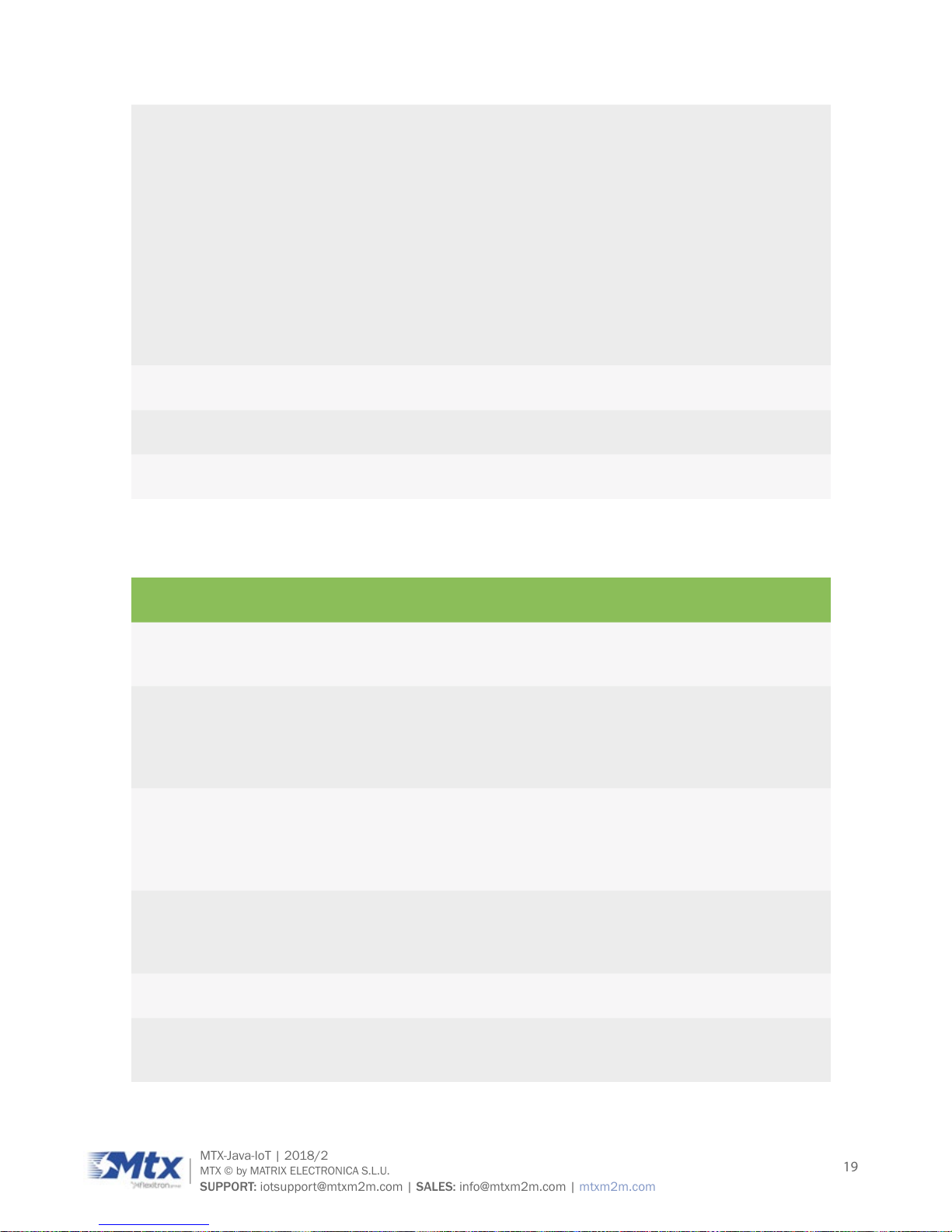
Java Open Platform Java Open Platform with
• JavaTM prole IMP-NG & CLDC 1.1 HI
• Secure data transmission via HTTPS/SSL
• Multi-threading programming and multi-application execution
Major benets: seamless integration into Java applications, ease
of programming, no need for application microcontroller, extremely
cost-efcient hardware and software design – an ideal platform for
industrial GSM applications.
The memory space available for Java programs is around 8MB in the
ash le system and around 6MB of RAM. Application code and data
share the space in the ash le system and in the RAM.
Microsoft compatibility RIL for Pocket PC and Smartphone
SIM Application Toolkit SAT letter classes b, c, e; with BIP
Firmware update Generic update from host application over ASC0 or USB modem
The following characteristics are common to MTX-3G-Java and MTX-4G-Java.
Interfaces (depending on models)
USB Supports a USB 2.0 High Speed (480Mbit/s) device interface, Full
Speed (12Mbit/s) compliant
RS232 (8-wire) Adjustable baud rates: 1200bps to 921600bps
Autobauding: 1200 to 230400bps
Supports RTS/CTS hardware ow control
Multiplex ability according to GSM 07.10 Multiplexer Protocol
RS232 (4-wire) Adjustable baud rates: 1200bps to 921600bps
Autobauding: 1200 to 230400bps
Supports RTS/CTS hardware ow control
Multiplex ability according to GSM 07.10 Multiplexer Protocol
RS485 Adjustable baud rates: 1200bps to 921600bps
Autobauding: 1200 to 230400bps
Half-duplex
I/O 3x inputs (2 optoisolated) and 2x outputs (optoisolated)
ADC 2x analog inputs, supporting 0-50V modes (other modes available
under request)
Page 20

20
MTX-Java-IoT | 2018/2
MTX © by MATRIX ELECTRONICA S.L.U.
SUPPORT: iotsupport@mtxm2m.com | SALES: info@mtxm2m.com | mtxm2m.com
Count input 3x pulse count input
1-Wire 1-Wire (master) bus for EEPROM, Temperature sensors, etc.
Status Bi-color LED to indicate network connectivity status
UICC interface Supported chip cards: UICC/SIM/USIM 3V, 1.8V
Antenna 50 Ohms. GSM/UMTS main antenna
Power on/off, Reset
Power on/off Automatic switch-on at power supply
Switch off by AT command
Switch off by hardware signal TURN_OFF
Automatic switch-off in case of high temperature or voltage conditions
Software Reset Orderly shutdown and reset by AT command
Hardware Reset Emergency reset by hardware signal TURN_OFF
Special Features
Antenna SAIC/DARP
Rx Diversity (receiver type 3i – 64-QAM)/MIMO
Page 21

21
MTX-Java-IoT | 2018/2
MTX © by MATRIX ELECTRONICA S.L.U.
SUPPORT: iotsupport@mtxm2m.com | SALES: info@mtxm2m.com | mtxm2m.com
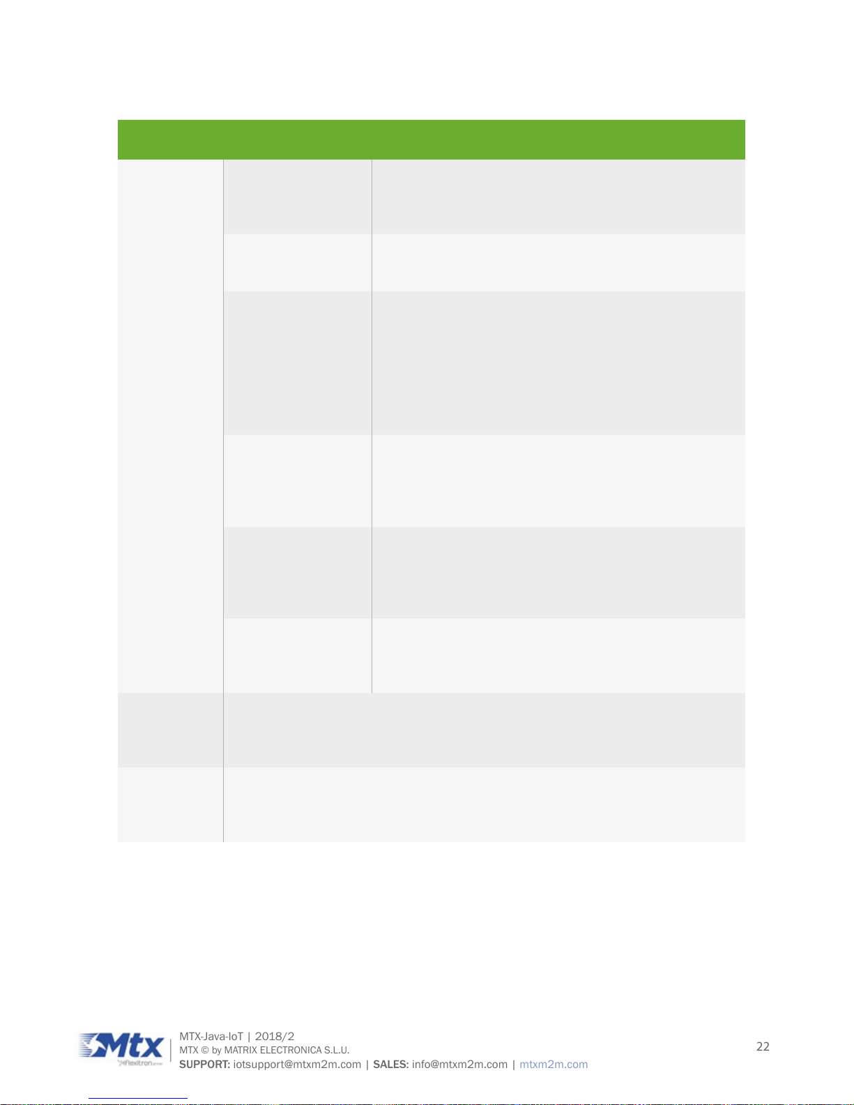
7.2 Operating modes
The table below briey summarizes the MTX-3G-Java operating modes referred to in the next chapters.
LIMITS FUNCTION
Normal
operation
GSM/GPRS/UMTS/
HSPA SLEEP
Power saving automatically activated when no calls
are in progress, the USB connection is suspended
by the host or not present, and there is no active
communication via ASC0.
GSM/GPRS/
UMTS/HSPA IDLE
Power saving is disabled if a USB connection is not
suspended, but no call is in progress.
GSM TALK/GSM
DATA
Connection between 2 subscribers in progress. Power
consumption depends on the GSM network coverage
and several connection settings (e.g. DTX off/on, FR/
EFR/HR, hopping sequences and antenna connection).
The following applies when power is to be measured in
TALK_GSM mode: DTX off, FR and no frequency hopping.
GPRS DATA GPRS data transfer in progress. Power consumption
depends on network settings (e.g. power control level),
uplink/downlink data rates and GPRS conguration (e.g.
used multislot settings).
EGPRS DATA EGPRS data transfer in progress. Power consumption
depends on network settings (e.g. power control level),
uplink/downlink data rates and EGPRS conguration
(e.g. used multislot settings).
UMTS TALK/UMTS
DATA
UMTS data transfer in progress. Power consumption
depends on network settings and data transfer rate.
HSPA DATA HSPA DATA
Low Power
mode
Available in “L” option devices. All the electronics systems remain disconnected
from the power supply input, with the exception of RS232/RS485 interfaces and
its controller. This allows to wake up the unit from those interfaces.
Ultra Low
Power mode
Available in “U” option devices. All the electronic systems remain disconnected
from the power supply input, with the exception of a little piece of logic which
allows for waking up the unit again from a tamper input or after a specied time.
Airplane
mode
Airplane mode shuts down the radio, causes the modem to log off from the
GSM/GPRS network, and disables all AT commands whose execution requires
radio connection. Airplane mode can be controlled by AT command.
Page 22
22
MTX-Java-IoT | 2018/2
MTX © by MATRIX ELECTRONICA S.L.U.
SUPPORT: iotsupport@mtxm2m.com | SALES: info@mtxm2m.com | mtxm2m.com
The table below briey summarizes the MTX-4G-Java operating modes referred to in the next chapters.
LIMITS FUNCTION
Normal
operation
GSM/GPRS/LTE
SLEEP
Power saving set automatically when no call is in
progress and the USB connection is suspended by host
or not present and no active communication via ASC0.
GSM/GPRS/LTE
IDLE
Power saving disabled or an USB connection not
suspended, but no call in progress.
GSM TALK/GSM
DATA
Connection between two subscribers is in progress.
Power consumption depends on the GSM network
coverage and several connection settings (e.g. DTX
off/on, FR/EFR/HR, hopping sequences and antenna
connection). The following applies when power is to
be measured in TALK_GSM mode: DTX off, FR and no
frequency hopping.
GPRS DATA GPRS data transfer in progress. Power consumption
depends on network settings (e.g. power control level),
uplink / downlink data rates and GPRS conguration
(e.g. used multislot settings).
EGPRS DATA EGPRS data transfer in progress. Power consumption
depends on network settings (e.g. power control level),
uplink / downlink data rates and EGPRS conguration
(e.g. used multislot settings).
LTE DATA LTE data transfer in progress. Power consumption
depends on network settings (e.g. TPC Pattern) and data
transfer rate.
Power Down Normal shutdown after sending the power down command. Only a voltage
regulator is active for powering the RTC. Software is not active. Interfaces are not
accessible. Operating voltage remains applied.
Airplane
mode
Airplane mode shuts down the radio part of the module, causes the module to
log off from the network and disables all AT commands whose execution requires
a radio connection. Airplane mode can be controlled by AT command.
Page 23
23
MTX-Java-IoT | 2018/2
MTX © by MATRIX ELECTRONICA S.L.U.
SUPPORT: iotsupport@mtxm2m.com | SALES: info@mtxm2m.com | mtxm2m.com
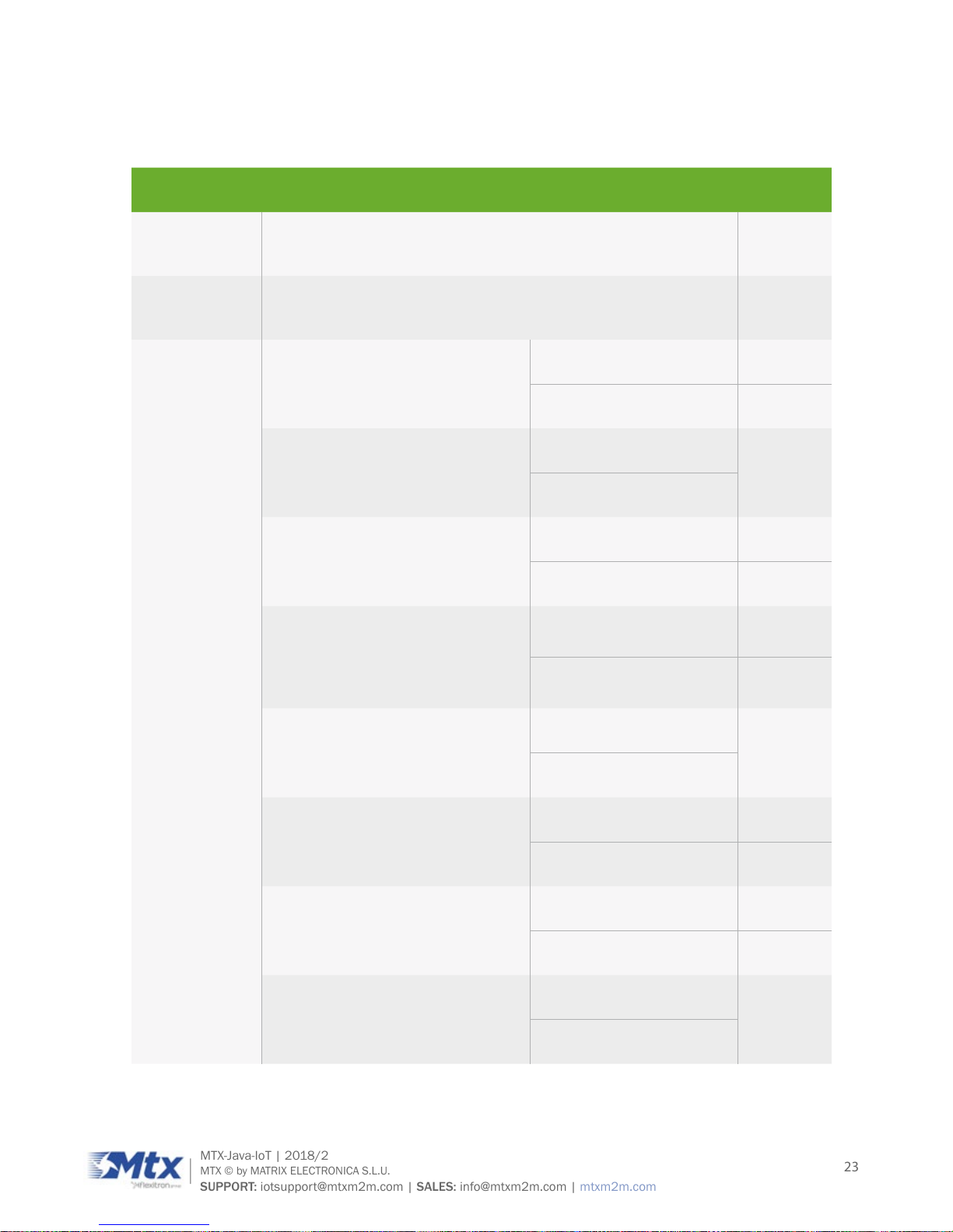
7.3 Power consumption
It is recommend to use 12V/1.5A power supply (IIN2)
DESCRIPTION CONDITIONS TYPICAL
ULP mode
supply current
Ultra Low Power Mode
25µA
Sleep mode
supply current
Internal GSM module powered down
7mA
Average
GSM/GPRS
supply current
IDLE (UART activated but no
communication) @ DRX=2
USB disconnected 11mA
USB active 12mA
GPRS Data transfer
GSM850/900; PCL=5; 1Tx/4Rx
ROPR=4 (max. reduction)
67mA
ROPR=0 (no reduction)
GPRS Data transfer
GSM850/900; PCL=5; 2Tx/3Rx
ROPR=4 (max. reduction) 84.5mA
ROPR=0 (no reduction) 115mA
GPRS Data transfer
GSM850/900; PCL=5; 4Tx/1Rx
ROPR=4 (max. reduction)
90mA
ROPR=0 (no reduction)
205mA
EDGE Data transfer
GSM850/900; PCL=5; 1Tx/4Rx
ROPR=4 (max. reduction)
50mA
ROPR=0 (no reduction)
EDGE Data transfer
GSM850/900; PCL=5; 2Tx/3Rx
ROPR=4 (max. reduction) 64.5mA
ROPR=0 (no reduction) 81mA
EDGE Data transfer
GSM850/900; PCL=5; 4Tx/1Rx
ROPR=4 (max. reduction) 97mA
ROPR=0 (no reduction) 136mA
GPRS Data transfer
GSM1800/1900; PCL=0; 1Tx/4Rx
ROPR=4 (max. reduction)
52mA
ROPR=0 (no reduction)
Page 24
24
MTX-Java-IoT | 2018/2
MTX © by MATRIX ELECTRONICA S.L.U.
SUPPORT: iotsupport@mtxm2m.com | SALES: info@mtxm2m.com | mtxm2m.com
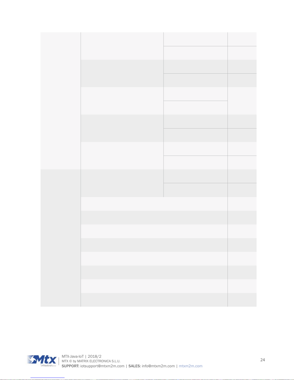
GPRS Data transfer
GSM1800/1900; PCL=0; 2Tx/3Rx
ROPR=4 (max. reduction) 57mA
ROPR=0 (no reduction) 85mA
GPRS Data transfer
GSM1800/1900; PCL=0; 4Tx/1Rx
ROPR=4 (max. reduction) 67mA
ROPR=0 (no reduction) 145mA
EDGE Data transfer
GSM1800/1900; PCL=0; 1Tx/4Rx
ROPR=4 (max. reduction)
45mA
ROPR=0 (no reduction)
EDGE Data transfer
GSM1800/1900; PCL=0; 2Tx/3Rx
ROPR=4 (max. reduction) 62mA
ROPR=0 (no reduction) 70mA
EDGE Data transfer
GSM1800/1900; PCL=0; 4Tx/1Rx
ROPR=4 (max. reduction) 95mA
ROPR=0 (no reduction) 115mA
Average
WCDMA
supply current
supply current
IDLE (UART activated but no
communication) @ DRX=6
USB disconnected 10mA
USB active
16mA
UMTS Data transfer Band I @ 23dBm 132mA
UMTS Data transfer Band II @ 23dBm 150mA
UMTS Data transfer Band V/VI @ 23dBm 150mA
UMTS Data transfer Band VIII @ 23dBm 152mA
HSPA Data transfer Band I @ 23dBm 132mA
HSPA Data transfer Band II @ 23dBm 150mA
HSPA Data transfer Band V/VI @ 23dBm 150mA
HSPA Data transfer Band VIII @ 23dBm 152mA
Page 25
25
MTX-Java-IoT | 2018/2
MTX © by MATRIX ELECTRONICA S.L.U.
SUPPORT: iotsupport@mtxm2m.com | SALES: info@mtxm2m.com | mtxm2m.com
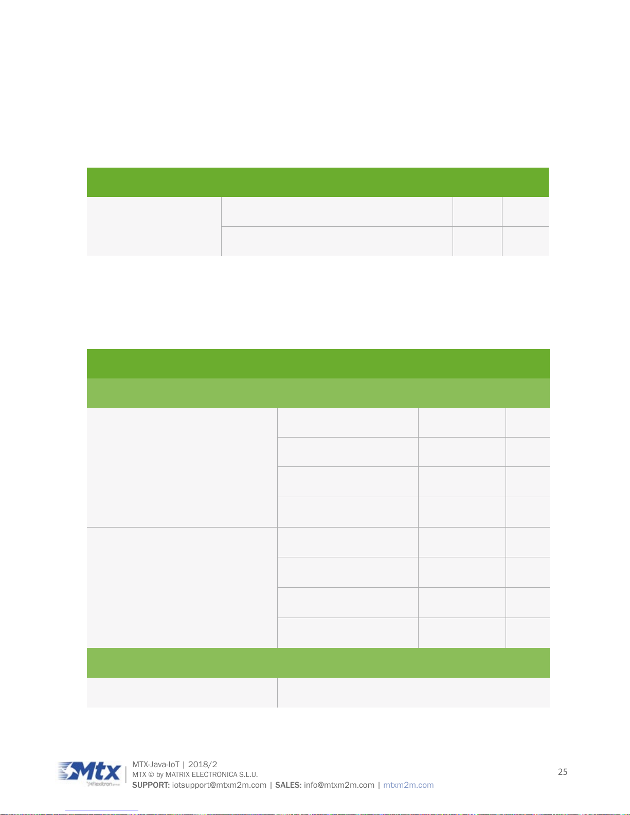
1. With an impedance of ZLOAD=50Ohm at the antenna port.
2. Measurements start 6 minutes after switching ON the modules.
Average times: SLEEP and ULP mode – 3 minutes, transfer modes – 1.5 minutes.
Communication tester settings: no neighbor cells, no cell reselection etc., RMC (reference
measurement channel).
DESCRIPTION CONDITIONS TYP MAX
ULP mode supply current
TA = 25ºC 25µA 35µA
TA = 85ºC 70µA 85µA
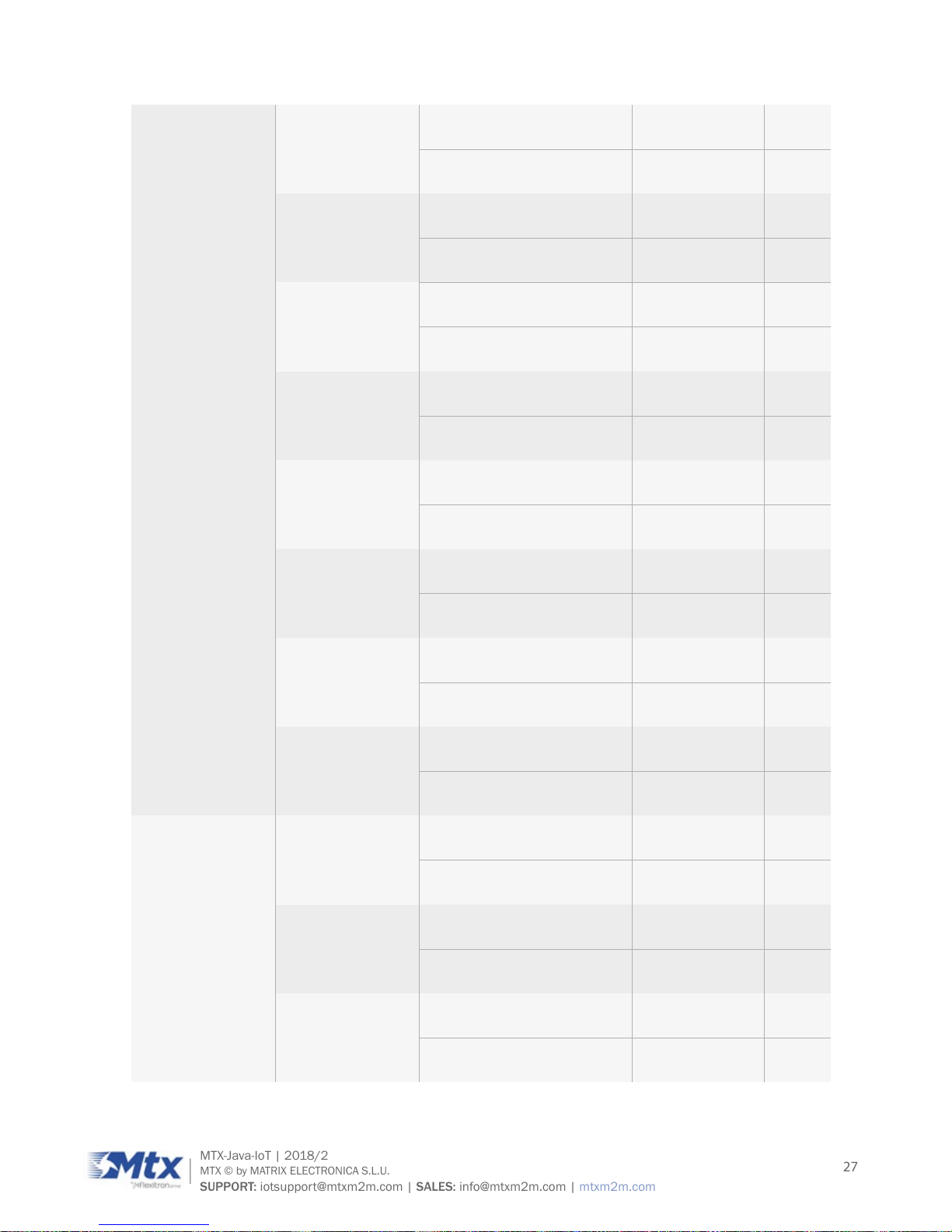
7.4 RF antenna interface description
The table below briey summarizes the RF Antenna interface GSM/UMTS (dBm).
PARAMETER CONDITIONS MIN TYP
UMTS/HSPA Connectivity Band I, II, V, VI, VIII
Receiver Input Sensitivity @ ARP UMTS 800/850 Band VI/V -104.7/-106.7 -110
UMTS 900 Band VIII -103.7 -110
UMTS 1900 Band II -104.7 -109
UMTS 2100 Band I -106.7 -110
RF Power @ ARP with 50Ohm Load UMTS 800/850 Band VI/V 21 (max 25) 24
UMTS 900 Band VIII 21 (max 25) 24
UMTS 1800 Band III 21 (max 25) 24
UMTS 2100 Band I 21 (max 25) 24
GPRS Coding Schemes
Class 12, CS1 to CS4
EGPRS Class 12, MCS1 to MCS9
Page 26
26
MTX-Java-IoT | 2018/2
MTX © by MATRIX ELECTRONICA S.L.U.
SUPPORT: iotsupport@mtxm2m.com | SALES: info@mtxm2m.com | mtxm2m.com
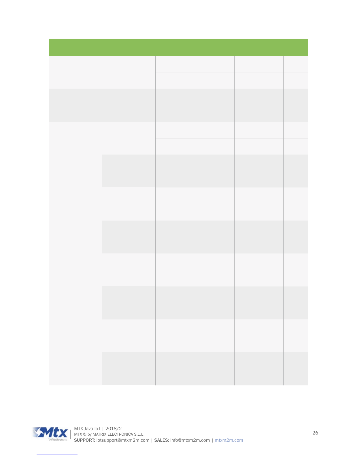
GSM Class
Small MS
Static Receiver Input Sensitivity @
ARP
GSM 850/E-GSM 900 -102 -109
GSM 1800/GSM 1900 -102 -108
RF Power @ ARP
with 50Ohm
Load
GSM GSM 850/E-GSM 900 33
GSM 1800/GSM 1900 30
RF Power @ ARP
with 50Ohm
Load, (ROPR
= 0, i.e. no
reduction)
GPRS, 1 TX GSM 850/E-GSM 900 33
GSM 1800/GSM 1900 30
EDGE, 1 TX GSM 850/E-GSM 900 27
GSM 1800/GSM 1900 26
GPRS, 2 TX GSM 850/E-GSM 900 33
GSM 1800/GSM 1900 30
EDGE, 2 TX GSM 850/E-GSM 900 27
GSM 1800/GSM 1900 26
GPRS, 3 TX GSM 850/E-GSM 900 33
GSM 1800/GSM 1900 30
EDGE, 3 TX GSM 850/E-GSM 900 27
GSM 1800/GSM 1900 26
GPRS, 4 TX GSM 850/E-GSM 900 33
GSM 1800/GSM 1900 30
EDGE, 4 TX GSM 850/E-GSM 900 27
GSM 1800/GSM 1900 26
Page 27
27
MTX-Java-IoT | 2018/2
MTX © by MATRIX ELECTRONICA S.L.U.
SUPPORT: iotsupport@mtxm2m.com | SALES: info@mtxm2m.com | mtxm2m.com
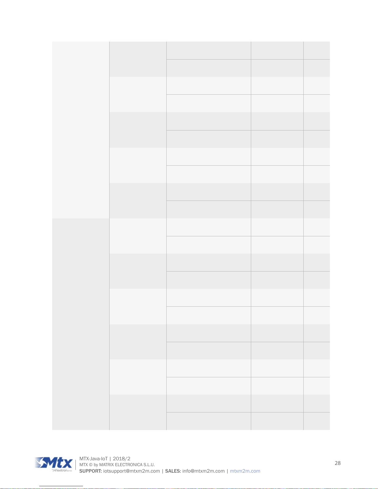
RF Power @ ARP
with 50Ohm
Load, (ROPR
= 1)
GPRS, 1 TX GSM 850/E-GSM 900 33
GSM 1800/GSM 1900 30
EDGE, 1 TX GSM 850/E-GSM 900 27
GSM 1800/GSM 1900 26
GPRS, 2 TX GSM 850/E-GSM 900 33
GSM 1800/GSM 1900 30
EDGE, 2 TX GSM 850/E-GSM 900 27
GSM 1800/GSM 1900 26
GPRS, 3 TX GSM 850/E-GSM 900 33
GSM 1800/GSM 1900 30
EDGE, 3 TX GSM 850/E-GSM 900 27
GSM 1800/GSM 1900 26
GPRS, 4 TX GSM 850/E-GSM 900 31
GSM 1800/GSM 1900 28
EDGE, 4 TX GSM 850/E-GSM 900 27
GSM 1800/GSM 1900 26
RF Power @ ARP
with 50Ohm
Load, (ROPR
= 2)
GPRS, 1 TX GSM 850/E-GSM 900 33
GSM 1800/GSM 1900 30
EDGE, 1 TX GSM 850/E-GSM 900 27
GSM 1800/GSM 1900 26
GPRS, 2 TX GSM 850/E-GSM 900 33
GSM 1800/GSM 1900 20
Page 28
28
MTX-Java-IoT | 2018/2
MTX © by MATRIX ELECTRONICA S.L.U.
SUPPORT: iotsupport@mtxm2m.com | SALES: info@mtxm2m.com | mtxm2m.com
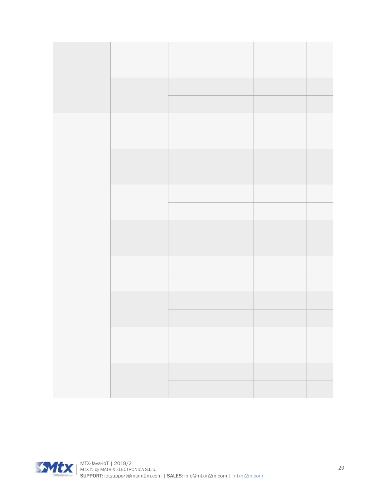
EDGE, 2 TX GSM 850/E-GSM 900 27
GSM 1800/GSM 1900 26
GPRS, 3 TX GSM 850/E-GSM 900 33
GSM 1800/GSM 1900 30
EDGE, 3 TX
GSM 850/E-GSM 900 27
GSM 1800/GSM 1900 26
GPRS, 4 TX GSM 850/E-GSM 900 29
GSM 1800/GSM 1900 26
EDGE, 4 TX GSM 850/E-GSM 900 27
GSM 1800/GSM 1900 26
RF Power @ ARP
with 50Ohm
Load, (ROPR
= 3)
GPRS, 1 TX GSM 850/E-GSM 900 33
GSM 1800/GSM 1900 30
EDGE, 1 TX GSM 850/E-GSM 900 27
GSM 1800/GSM 1900 26
GPRS, 2 TX GSM 850/E-GSM 900 33
GSM 1800/GSM 1900 30
EDGE, 2 TX GSM 850/E-GSM 900 27
GSM 1800/GSM 1900 26
GPRS, 3 TX GSM 850/E-GSM 900 33
GSM 1800/GSM 1900 30
EDGE, 3 TX GSM 850/E-GSM 900 27
GSM 1800/GSM 1900 26
Page 29
29
MTX-Java-IoT | 2018/2
MTX © by MATRIX ELECTRONICA S.L.U.
SUPPORT: iotsupport@mtxm2m.com | SALES: info@mtxm2m.com | mtxm2m.com
GPRS, 4 TX GSM 850/E-GSM 900 27
GSM 1800/GSM 1900 24
EDGE, 4 TX GSM 850/E-GSM 900 27
GSM 1800/GSM 1900 24
RF Power @ ARP
with 50Ohm
Load, (ROPR =
4, i.e. maximum
reduction)
GPRS, 1 TX GSM 850/E-GSM 900 33
GSM 1800/GSM 1900 30
EDGE, 1 TX GSM 850/E-GSM 900 27
GSM 1800/GSM 1900 26
GPRS, 2 TX GSM 850/E-GSM 900 30
GSM 1800/GSM 1900 27
EDGE, 2 TX GSM 850/E-GSM 900 24
GSM 1800/GSM 1900 23
GPRS, 3 TX GSM 850/E-GSM 900 28.2
GSM 1800/GSM 1900 25.2
EDGE, 3 TX GSM 850/E-GSM 900 22.2
GSM 1800/GSM 1900 21.2
GPRS, 4 TX GSM 850/E-GSM 900 27
GSM 1800/GSM 1900 24
EDGE, 4 TX GSM 850/E-GSM 900 21
GSM 1800/GSM 1900 20
Page 30
30
MTX-Java-IoT | 2018/2
MTX © by MATRIX ELECTRONICA S.L.U.
SUPPORT: iotsupport@mtxm2m.com | SALES: info@mtxm2m.com | mtxm2m.com
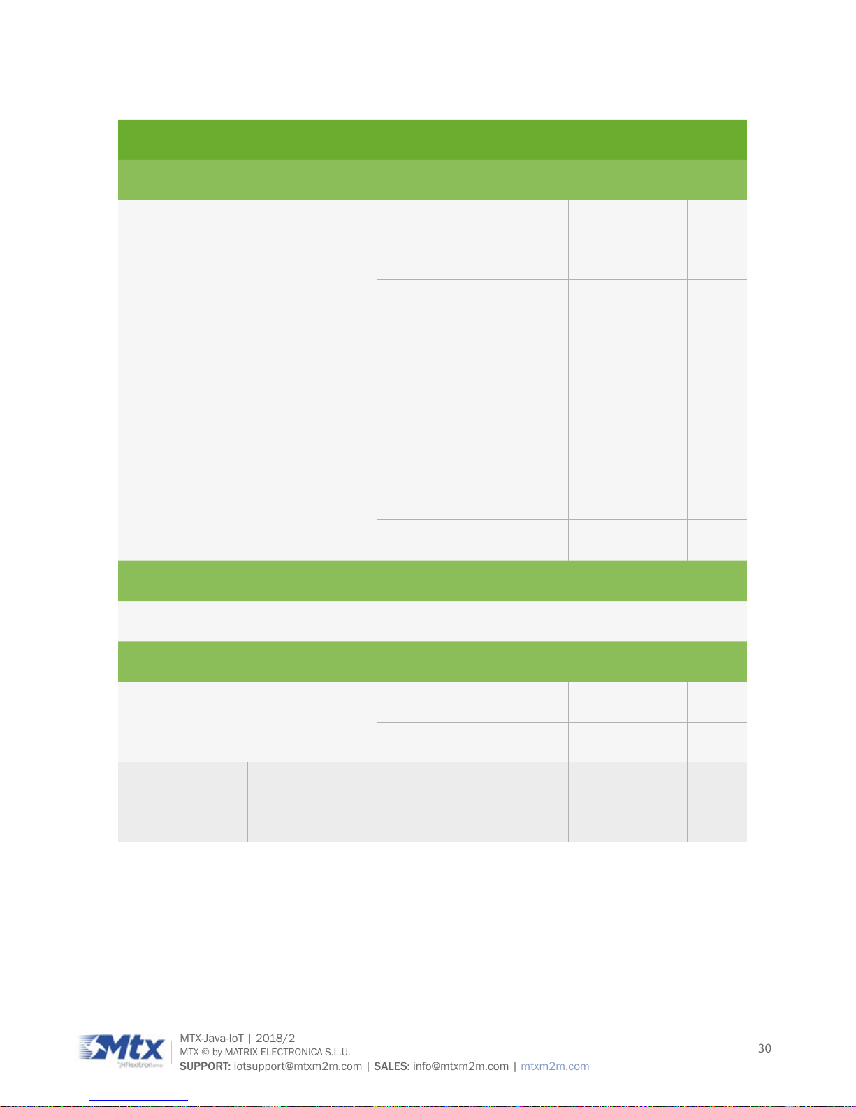
The table below briey summarizes the RF Antenna interface LTE (dBm).
PARAMETER CONDITIONS MIN TYP
LTE Connectivity Band 1, 3, 8, 20
Receiver Input Sensitivity @ARP (ch.
bandwidth 5MHz)
LTE 800 Band 20 -97
LTE 900 Band 8 -97
LTE 1800 Band 3 -97
LTE 2100 Band 1 -100
RF Power @ ARP with 50Ω Load
(Dual Antenna; power supply: 3.8V;
temperature 25°C)
LTE 800 Band 20 23
LTE 900 Band 8 23
LTE 1800 Band 3 23
LTE 2100 Band 1 23
GPRS Coding Schemes
Class 12, CS1 to CS4
EGPRS Class 12, MCS1 to MCS9
GSM Class
Small MS
Static Receiver Input Sensitivity @
ARP
GSM 900 -102 -109
GSM 1800 -102 -108
RF Power @ ARP
with 50Ω Load
GSM GSM 900 32.5
GSM 1800 29.5
Page 31

31
MTX-Java-IoT | 2018/2
MTX © by MATRIX ELECTRONICA S.L.U.
SUPPORT: iotsupport@mtxm2m.com | SALES: info@mtxm2m.com | mtxm2m.com
RF Power @ ARP
with 50Ω Load,
(ROPR = 0, i.e.
no reduction)
GPRS, 1 TX GSM 900 32.5
GSM 1800 29.5
EDGE, 1 TX GSM 900 27
GSM 1800 26
GPRS, 2 TX GSM 900 32.5
GSM 1800 29.5
EDGE, 2 TX GSM 900 27
GSM 1800 26
GPRS, 3 TX GSM 900 32.5
GSM 1800 29.5
EDGE, 3 TX GSM 900 27
GSM 1800 26
GPRS, 4 TX GSM 900 32.5
GSM 1800 29.5
EDGE, 4 TX GSM 900 27
GSM 1800 26
RF Power @ ARP
with 50Ω Load,
(ROPR = 1)
GPRS, 1 TX GSM 900 32.5
GSM 1800 29.5
EDGE, 1 TX GSM 900 27
GSM 1800 26
GPRS, 2 TX GSM 900 32.5
GSM 1800 29.5
Page 32

32
MTX-Java-IoT | 2018/2
MTX © by MATRIX ELECTRONICA S.L.U.
SUPPORT: iotsupport@mtxm2m.com | SALES: info@mtxm2m.com | mtxm2m.com
EDGE, 2 TX GSM 900 27
GSM 1800 26
GPRS, 3 TX GSM 900 31.5
GSM 1800 28.5
EDGE, 3 TX GSM 900 27
GSM 1800 26
GPRS, 4 TX GSM 900 30.5
GSM 1800 27.5
EDGE, 4 TX GSM 900 27
GSM 1800 26
RF Power @ ARP
with 50Ω Load,
(ROPR = 2)
GPRS, 1 TX GSM 900 32.5
GSM 1800 29.5
EDGE, 1 TX GSM 900 27
GSM 1800 26
GPRS, 2 TX GSM 900 30.5
GSM 1800 27.5
EDGE, 2 TX GSM 900 27
GSM 1800 26
GPRS, 3 TX GSM 900 29.5
GSM 1800 26.5
EDGE, 3 TX
GSM 900 27
GSM 1800 26
Page 33

33
MTX-Java-IoT | 2018/2
MTX © by MATRIX ELECTRONICA S.L.U.
SUPPORT: iotsupport@mtxm2m.com | SALES: info@mtxm2m.com | mtxm2m.com
GPRS, 4 TX GSM 900 28.5
GSM 1800 25.5
EDGE, 4 TX GSM 900 27
GSM 1800 26
RF Power @ ARP
with 50Ω Load,
(ROPR = 3)
GPRS, 1 TX GSM 900 32.5
GSM 1800 29.5
EDGE, 1 TX GSM 900 27
GSM 1800 26
GPRS, 2 TX GSM 900 29.5
GSM 1800 26.5
EDGE, 2 TX GSM 900 27
GSM 1800 26
GPRS, 3 TX GSM 900 27.5
GSM 1800 24.5
EDGE, 3 TX GSM 900 27
GSM 1800 26
GPRS, 4 TX GSM 900 26.5
GSM 1800 23.5
EDGE, 4 TX GSM 900 27
GSM 1800 26
Page 34

34
MTX-Java-IoT | 2018/2
MTX © by MATRIX ELECTRONICA S.L.U.
SUPPORT: iotsupport@mtxm2m.com | SALES: info@mtxm2m.com | mtxm2m.com
RF Power @
ARP with 50Ω
Load, (ROPR =
4, i.e. maximum
reduction)
GPRS, 1 TX GSM 900 32.5
GSM 1800 29.5
EDGE, 1 TX GSM 900 27
GSM 1800 26
GPRS, 2 TX GSM 900 29.5
GSM 1800 26.5
EDGE, 2 TX GSM 900 24
GSM 1800 23
GPRS, 3 TX GSM 900 27.5
GSM 1800 24.5
EDGE, 3 TX GSM 900 22
GSM 1800 21
GPRS, 4 TX GSM 900 26.5
GSM 1800 23.5
EDGE, 4 TX GSM 900 21
GSM 1800 20
7.5 SIM card
The MTX-Java-IoT supports an external SIM card through the integrated SIM holder. Both 3V and 1.8V
SIM technology is supported. Older 5V SIM technology is not supported.
Page 35

35
MTX-Java-IoT | 2018/2
MTX © by MATRIX ELECTRONICA S.L.U.
SUPPORT: iotsupport@mtxm2m.com | SALES: info@mtxm2m.com | mtxm2m.com
8. Precautions
MTX-Java-IoT as a standalone item is designed for indoor use only. For outdoor use it must be integrated
into a weatherproof enclosure. Do not exceed the environmental and electrical limits as specied in
Technical Data.
Page 36

36
MTX-Java-IoT | 2018/2
MTX © by MATRIX ELECTRONICA S.L.U.
SUPPORT: iotsupport@mtxm2m.com | SALES: info@mtxm2m.com | mtxm2m.com
9. Block Diagram
9.1 Models with Power Relay 220VAC/6A
The MTX-Java-IoT modems containing a 220VAC/6A Power relay have the following block diagram:
Plug-in 5-way
terminal block
Battery
Power: 7-50 VDC
Internal Co-processor
Cinterio Cellular M2M module
220 VAC/6A
Relay
Mini USB
DB9 (*1)
Internal
Wireless
module
GPIO
ADC
DB15 (I/O expansion port) (*2)
SIM Card
Reader
External
Power
Opto I/O
Analog IN
I2C
VREF
Count
input
RS232
(4-Wire)
RS232
(8-Wire)
USB 2.0
High Speed
ASC1ASC0
GPS Antenna
SMA F
UMTS/GSM
Antenna
FME M
LED signaling
Note *1: DB9 connector only available in STD and DB9 variants. See section Introduction 2 (Ordering
Information)
Note *2: DB15 HD connector only available in STD and DB15 variants. See section Introduction 2
(Ordering Information)
Page 37

37
MTX-Java-IoT | 2018/2
MTX © by MATRIX ELECTRONICA S.L.U.
SUPPORT: iotsupport@mtxm2m.com | SALES: info@mtxm2m.com | mtxm2m.com
9.2 Models with RJ11 connector and/or analog audio
The MTX-Java-IoT modems with RJ11 connectors and/or analog audio have the following block diagram:
RJ11 Power
Battery
Power: 7-50 VDC
Internal Co-processor
Cinterio Cellular M2M module
Mini USB
DB9 (*1)
Internal
Wireless
module
GPIO
ADC
DB15 (I/O expansion port) (*2)
SIM Card
Reader
External
Power
Opto I/O
Analog IN
I2C
VREF
Count
input
RS232
(4-Wire)
RS232
(8-Wire)
USB 2.0
High Speed
ASC1ASC0
GPS Antenna
SMA F
UMTS/GSM
Antenna
FME M
LED signaling
RJ11 Audio
Note *1: DB9 connector only available in STD and DB9 variants. See section Introduction 2 (Ordering
Information)
Note *2: DB15 HD connector only available in STD and DB15 variants. See section Introduction 2
(Ordering Information)
Page 38

38
MTX-Java-IoT | 2018/2
MTX © by MATRIX ELECTRONICA S.L.U.
SUPPORT: iotsupport@mtxm2m.com | SALES: info@mtxm2m.com | mtxm2m.com
9.3 Models with 5-way terminal block
The general MTX-Java-IoT modem’s block diagram is shown in the following gure:
Plug-in 5-way
terminal block
Battery
Power: 7-50 VDC
Internal Co-processor
Cinterio Cellular M2M module
Mini USB
DB9 (*1)
Internal
Wireless
module
GPIO
ADC
DB15 (I/O expansion port) (*2)
SIM Card
Reader
External
Power
Opto I/O
Analog IN
I2C
VREF
Count
input
RS232
(4-Wire)
USB 2.0
High Speed
ASC1ASC0
GPS Antenna
SMA F
UMTS/GSM
Antenna
FME M
LED signaling
RS485
Note *1: DB9 connector only available in STD and DB9 variants. See section Introduction 2 (Ordering
Information)
Note *2: DB15 HD connector only available in STD and DB15 variants. See section Introduction 2
(Ordering Information)
Page 39

39
MTX-Java-IoT | 2018/2
MTX © by MATRIX ELECTRONICA S.L.U.
SUPPORT: iotsupport@mtxm2m.com | SALES: info@mtxm2m.com | mtxm2m.com
10. Hardware Revisions
HARDWAREREVISION STARTING PRODUCTION DATE CHANGES
1.03 2016/02 Initial version
Page 40

40
MTX-Java-IoT | 2018/2
MTX © by MATRIX ELECTRONICA S.L.U.
SUPPORT: iotsupport@mtxm2m.com | SALES: info@mtxm2m.com | mtxm2m.com
MECHANICAL DESCRIPTION
1. Overview
1.1 Models with 5-way plug-in 5.00mm pitch terminal block
The pictures below show the mechanical design of the unit along with the positions of the different
connectors and mounting holes. The device case is made of durable PC/ABS plastic.
FME antenna (3G)
SMA antenna (4G)
Tri-color LED indicator
DB9
DB15
SIM card reader
DIP switches and battery jumper
Optional GPS (3G)
Micro USB
5-way plug-in 5.00mm
pitch terminal block
Mounting holes
Page 41

41
MTX-Java-IoT | 2018/2
MTX © by MATRIX ELECTRONICA S.L.U.
SUPPORT: iotsupport@mtxm2m.com | SALES: info@mtxm2m.com | mtxm2m.com
1.2 Models with RJ11 connector
The pictures below show the mechanical design of the unit along with the positions of the different
connectors and mounting holes. The modem case is made of durable PC/ABS plastic.
Mini USB
Power supply
Audio connector
Mounting holes
Page 42

42
MTX-Java-IoT | 2018/2
MTX © by MATRIX ELECTRONICA S.L.U.
SUPPORT: iotsupport@mtxm2m.com | SALES: info@mtxm2m.com | mtxm2m.com
2. Dimensions (mm)
78.1
37.2
66.8
71.5
11
3.5
Packaging:
Box 15 units: 37cm x 32cm x 4cm, 1.211Kg
Box 150 units (contains 10 boxes of 15 units): 38cm x 33cm x 48cm, 20Kg
Page 43

43
MTX-Java-IoT | 2018/2
MTX © by MATRIX ELECTRONICA S.L.U.
SUPPORT: iotsupport@mtxm2m.com | SALES: info@mtxm2m.com | mtxm2m.com
ELECTRICAL AND ENVIRONMENTAL
CHARACTERISTICS
1. Electrical specications
1.1 Power supply
ABSOLUTE MAXIMUM RATINGS
Symbol Parameter Conditions Min Max Unit
VIN Supply voltage -0.3 65 V
CHARACTERISTICS
Symbol Parameter Conditions Min Typ Max Unit
VIN Supply voltage 7 50 V
IIN Supply current -
*
- A
η
Efciency VIN=24V, IOUT=1.5A 87 %
f
o Switching frequency 500 kHz
*See section Introduction 7.3 (Power Consumption)
Page 44

44
MTX-Java-IoT | 2018/2
MTX © by MATRIX ELECTRONICA S.L.U.
SUPPORT: iotsupport@mtxm2m.com | SALES: info@mtxm2m.com | mtxm2m.com
1.2 RS232 interface
ABSOLUTE MAXIMUM RATINGS
Symbol Parameter Conditions Min Max Unit
V
I Input voltage range
Drivers -0.3 65 V
Receivers -25 25 V
V
o Output voltage range
Drivers -13.2 13.2 V
Receivers -0.3 5 V
Electrostatic discharge Human body model 2 kV
CHARACTERISTICS
Symbol Parameter Conditions Min Typ Max Unit
V
OH
Driver high-level output
voltage
RL=3kΩ to GND 5 5.4 V
V
OL
Driver low-level output
voltage
RL=3kΩ to GND -5 5.4 V
r
o Driver output resistance VIN = 0V 300 10M Ω
V
IT+
Receiver positive-going
input threshold voltage
1.5 2.4 V
V
IT-
Receiver negative-going
input threshold voltage
0.6 1.2 V
V
hys
Receiver input hysteresis
(VIT+ - VIT-)
0.3 V
r
i Receiver input resistance
Input voltage
±3 to ±25V
3 5 7 kΩ
Page 45

45
MTX-Java-IoT | 2018/2
MTX © by MATRIX ELECTRONICA S.L.U.
SUPPORT: iotsupport@mtxm2m.com | SALES: info@mtxm2m.com | mtxm2m.com
1.3 RS485 interface
ABSOLUTE MAXIMUM RATINGS
Symbol Parameter Conditions Min Max Unit
V
I
Voltage input range, transient
pulse, A & B, through 100 Ω
±50 V
I
o Receiver output current ±11 mA
Electrostatic discharge
Human body model ±16 kV
Charged-device model ±1 kV
CHARACTERISTICS
Sym Parameter Conditions Min Typ Max Ut
|V
OD|
Driver differential
output voltage
I
O =0 2 3 V
R
L=54kΩ -5 -5.4 V
C(
OD)
Driver differential
output capacitance
VOD
=0.4sin(4Eπt)+0.5V
16 pF
I
OS
Driver short-circuit
output current
250 mA
V
IT+
Receiver positive-going
input threshold voltage
IO =-8mA -0.065 -0.01 V
V
IT-
Receiver negative-going
input threshold voltage
IO =8mA -0.2 -0.1 V
V
hys
Receiver input
hysteresis (VIT+ - VIT-)
35 mV
C(
ID)
Receiver differential
input capacitance
VOD
=0.4sin(4Eπt)+0.5V
15 pF
Page 46

46
MTX-Java-IoT | 2018/2
MTX © by MATRIX ELECTRONICA S.L.U.
SUPPORT: iotsupport@mtxm2m.com | SALES: info@mtxm2m.com | mtxm2m.com
1.4 Counter input
ABSOLUTE MAXIMUM RATINGS
Symbol Parameter Conditions Min Max Unit
V
I Input voltage range -12 40 V
CHARACTERISTICS
Symbol Parameter Conditions Min Typ Max Unit
V
IH High-level input voltage
2.0
V
V
IL Low-level input voltage
0.9
V
1.5 Optoisolated input/output
ABSOLUTE MAXIMUM RATINGS (TCMD4000 OPTOCOUPLER)
Symbol Parameter Conditions Mn Max Unit
Input
V
R Reverse voltage 6 V
I
F Forward current 60 mA
I
FSM Forward surge current 1.5 A
P
diss
Power dissipation
100 mW
Output
V
CEO
Collector-emitter voltage
35 V
V
ECO
Emitter-collector voltage
7 V
I
C
Collector current
80 mA
Page 47

47
MTX-Java-IoT | 2018/2
MTX © by MATRIX ELECTRONICA S.L.U.
SUPPORT: iotsupport@mtxm2m.com | SALES: info@mtxm2m.com | mtxm2m.com
ICM
Collector peak current
tP/T=0.5, tP ≤ 10ms 100 mA
P
diss
Power dissipation
150 mW
Coupler
V
ISO
AC isolation test voltage (RMS)
3750 VRMS
Ptot
Total power dissipation
250 mW
CHARACTERISTICS (TCMD4000 OPTOCOUPLER)
Symbol Parameter Conditions Min Typ Max Unit
Input
V
F Forward voltage IF =50mA 1.25 1.6 V
C
j Junction capacitance VR =0V, f=1MHz 50 pF
Output
V
CEO Collector-emitter voltage IC =100µA 35 V
V
ECO Emitter-collector voltage IE =100µA 7 V
I
CEO Collector dark current VCE=10V, IF =0 100 nA
Coupler
V
CEsat
Collector-emitter
saturation voltage
IF =50V, IC =5mA 1 V
f
c Cut-off frequency
IF =10mA, VCE=5V,
RL=100Ω
10 kHz
C
k Coupling capacitance f=1MHz 0.3 pF
I
C /IF Current transfer ratio VCE =2V, IF=1mA 600 800 %
Page 48

48
MTX-Java-IoT | 2018/2
MTX © by MATRIX ELECTRONICA S.L.U.
SUPPORT: iotsupport@mtxm2m.com | SALES: info@mtxm2m.com | mtxm2m.com
tr Rise time
VCE =2V, IF=1mA,
R
L=100Ω
300 µs
t
off Turn-off time
VCE =2V, IF=1mA,
RL=100Ω
250 µs
Please see equivalent circuits in section DB15 HD Connector: I/O expansion port 4.4 (Optoisolated I/O)
to view voltage input/output ranges and determine operating conditions in each case.
1.6 Analog input/output
ABSOLUTE MAXIMUM RATINGS
Symbol Parameter Conditions Min Max Unit
V
I Input voltag Voltage mode -12.5 85 V
I
I Input current Current mode -6 42 mA
Electrostatic discharge
Human body model 2000 V
Charge device model 500 V
CHARACTERISTICS
Symbol Parameter Conditions Min Max Unit
V
oa Analog output voltage range
No resistive load 0 3 V
RL=10kΩ 0 2.7 V
Internal Ref. voltage Initial trimming, 25ºC ±0.1 %
V
OS Input Offset Error Voltage mode (0-50V) ±50 mV
G
E Gain Error ±0.1 %
PSRR Power Supply Reject. Ratio 70 dB
CMRR Common Mode Reject. Ratio 70 dB
Page 49

49
MTX-Java-IoT | 2018/2
MTX © by MATRIX ELECTRONICA S.L.U.
SUPPORT: iotsupport@mtxm2m.com | SALES: info@mtxm2m.com | mtxm2m.com
INL Integral non linearity Input voltage ±3-±25V 3 ±2 LSB
DNL Differential non linearity ±2 LSB
1.7 1-wire (by request)
ABSOLUTE MAXIMUM RATINGS
Symbol Parameter Conditions Min Max Unit
V
I Input voltage
-0.5 6 V
Transient pulse -100 100 V
CHARACTERISTICS
Symbol Parameter Conditions Min Typ Max Unit
V
IH1 Input High 1.9 V
V
IL1 Input Low 0.9 V
R
WPU Weak pullup resistor 1000 1675 Ω
V
OL1 Output Low At 4mA load 0.4 V
1.8 Power relay
CHARACTERISTICS
Sym Parameter Conditions Typ Max Unit
Contact rating
DC 6/30 A/V
AC 6/250 A/V
R
C Contact resistance At 1A 6VDC 100 mΩ
Page 50

50
MTX-Java-IoT | 2018/2
MTX © by MATRIX ELECTRONICA S.L.U.
SUPPORT: iotsupport@mtxm2m.com | SALES: info@mtxm2m.com | mtxm2m.com
ISW Switching current 6 A
V
SW Switching voltage
DC 125 V
AC 400 V
Electrical endurance
Resistive load, at 85ºC, 1s
on 9s off, 6A 250VAC
3x10
4 cycles
Mechanical endurance 10
7 cycles
R
I Insulation resistance At 500VDC 1000 MΩ
1.9 Latch relay
CHARACTERISTICS
Sym Parameter Conditions Typ Max Unit
Contact rating
DC 1/30 A/V
AC 0.5/125 A/V
R
C Contact resistance At 10mA 30mVDC 100 mΩ
I
SW Switching current 2 A
V
SW Switching voltage
DC 110 V
AC 125 V
Electrical endurance
Resistive load, at 70ºC, 1s
on 9s off, 0.5A 125VAC
10
5 cycles
Mechanical endurance 10
8 cycles
R
I Insulation resistance At 500VDC 1000 MΩ
Page 51

51
MTX-Java-IoT | 2018/2
MTX © by MATRIX ELECTRONICA S.L.U.
SUPPORT: iotsupport@mtxm2m.com | SALES: info@mtxm2m.com | mtxm2m.com
2. Operating Temperatures
Please note that the modem’s lifetime, i.e., the MTTF (mean time to failure) may be reduced if operated
outside the extended temperature range.
PARAMETER MIN TYP MAX UNIT
Normal operation -30 25 85 ºC
Extended operation -40 90 ºC
Automatic shutdown <-40 >90 ºC
1. Extended operation allows normal mode speech calls or data transmissions for a limited time
until the automatic thermal shutdown mode takes effect. Within the extended temperature
range (outside the operating temperature range) the specied electrical characteristics may
be increased or decreased.
2. Due to uncertainty in temperature measurement, a tolerance of ±3ºC on the stated shutdown
thresholds may occur.
Note that within the specied operating temperature ranges the unit temperature may vary to a great
extent depending on the operating mode, used frequency band, radio output power and current supply
voltage.
Page 52

52
MTX-Java-IoT | 2018/2
MTX © by MATRIX ELECTRONICA S.L.U.
SUPPORT: iotsupport@mtxm2m.com | SALES: info@mtxm2m.com | mtxm2m.com
3. Storage Conditions
The conditions stated below are only valid for modems in their original packed state in weather protected,
non-temperature-controlled storage locations. Normal storage time under these conditions is a maximum
of 12 months. The units will be delivered in a packaging that meets the requirements according “IPD/
JEDEC J-STD-033B.1” for Low Temperature Carriers.
TYPE CONDITION UNIT REFERENCE
Air temperature: Low
High
-30
75
ºC
ETS 300 019-2-1: T1.2, IEC 60068-2-1 Ab
ETS 300 019-2-1: T1.2, IEC 60068-2-2 Db
Relative humidity: Low
High
Cond.
10
90 at 30ºC
90-100 at 30ºC
%
-
ETS 300 019-2-1: T1.2, IEC 60068-2-56 Cb
ETS 300 019-2-1: T1.2, IEC 60068-2-30 Db
Air pressure: Low
High
70
106
kPa
IEC TR 60271-3-1:1K4
IEC TR 60271-3-1:1K4
Movement of air 1.0 m/s
IEC TR 60271-3-1:1K4
Water: rain, dripping,
icing and frosting
Not allowed - -
Radiation: Solar
Heat
1120
600
W/m2
ETS 300 019-2-1: T1.2, IEC 60068-2-2Bb
ETS 300 019-2-1: T1.2, IEC 60068-2-2Bb
Chemically active subs. Not recomm.
IEC TR 60271-3-1:1C1L
Mechanically active subs. Not recomm.
IEC TR 60271-3-1:1S1
Sinusoidal vibration:
Displacement
Acceleration
Frequency range
1.5
5
2-9 9-200
mm
m/s2
Hz
IEC TR 60271-3-1:1M2
Shocks:
Shock spectrum
Duration
Acceleration
semi-sinusoidal
1
50
ms
m/s2
IEC 60068-2-27 Ea
Page 53

53
MTX-Java-IoT | 2018/2
MTX © by MATRIX ELECTRONICA S.L.U.
SUPPORT: iotsupport@mtxm2m.com | SALES: info@mtxm2m.com | mtxm2m.com
INTERFACE DESCRIPTION
All electrical connections to the modem are protected in compliance with the standard air and contact
Electrostatic Discharge (ESD).
The modem family uses the following industry standard connectors:
• USB mini connector
• DB9 female (main RS232 port)
• DB15 HD female (I/O expansion connector)
• RJ11 6-way (power supply connector)
• 5-way plug-in 5.00mm pitch terminal block (power supply, RS485 bus and relay)
• SIM card reader
• FME male coaxial jack (antenna connector)
• SMA female coaxial jack (GPS/GNSS antenna connector) or other RF options
Page 54

54
MTX-Java-IoT | 2018/2
MTX © by MATRIX ELECTRONICA S.L.U.
SUPPORT: iotsupport@mtxm2m.com | SALES: info@mtxm2m.com | mtxm2m.com
1. Power Supply Connector
Depending on the specic modem you are using, you will dispose of one of the connectors described in
the sections below. Please read them carefully.
1.1 Models with Power Relay 220V/6A (5-way plug-in 5.00mm pitch terminal
block)
A 5-way plug-in terminal block connector shared with a 220VAC/6A relay, as shown and described below,
supplies the D.C. power to the modem.
The supply voltage, VCC, required by the modem is in the range of 7 to 50VDC. We recommend a 12VDC
power supply. The power supply has to be a single voltage source capable of providing a peak during an
active transmission. The uplink burst causes strong ripples (drop) on the power lines.
By default, the MTX-Java-IoT will automatically switch on when power supply is applied between PIN 2
and PIN 1.
12345
PIN SIGNAL DIRECTION LIMITS DESCRIPTION
1 GND Input Negative power (ground)
2 VIN Input 7-50VDC Positive power input
3 RL_NC 220VAC/6A relay Normally Close contact
4 RL_COM 220VAC/6A relay Common contact
5 RL_NO 220VAC/6A relay Normally Open contact
Page 55

55
MTX-Java-IoT | 2018/2
MTX © by MATRIX ELECTRONICA S.L.U.
SUPPORT: iotsupport@mtxm2m.com | SALES: info@mtxm2m.com | mtxm2m.com
1.2 Models with RJ11 connector
An RJ11 6-way connector, as shown and described below, serves as a means of supplying DC power to
the modem.
The power supply voltage (VCC) required by the modem is in the range of 7 to 50VDC. We recommend a
12V DC power supply. The power supply has to be a single voltage source capable of providing a current
peak during an active transmission. The uplink burst causes strong ripples (drop) on the power lines.
MTX-Java-IoT devices are shipped to automatically switch on only with supply between PIN 1 and PIN 6.
1 2 3 4 5 6
PIN SIGNAL DIRECTION LIMITS DESCRIPTION
1 VIN Input 6.5-40VDC Positive power input
2 TAMP- Output Vmax: VIN
ULP negative wake-up input (see section
Interface Description 13 (Real TIme
Clock))
3 NC Not connected
4 NC Not connected
5 TAMP+ Input 0-VIN
ULP positive wake-up input (see section
Interface Description 13 (Real TIme
Clock))
6 GND Input Negative power (ground)
Page 56

56
MTX-Java-IoT | 2018/2
MTX © by MATRIX ELECTRONICA S.L.U.
SUPPORT: iotsupport@mtxm2m.com | SALES: info@mtxm2m.com | mtxm2m.com
1.3 All other models (5-way plug-in 5.00mm pitch terminal block)
A 5 way plug-in terminal block connector shared with RS485 bus, as shown and described below, supplies
D.C. power to the modem.
The supply voltage, VCC, required by the modem is in the range of 7 to 50VDC. We recommend a 12VDC
power supply. The power supply has to be a single voltage source capable of providing a peak during an
active transmission. The uplink burst causes strong ripples (drop) on the power lines.
By default, the MTX-Java-IoT will automatically switch on when power supply is applied between PIN 2
and PIN 1.
12345
PIN SIGNAL DIRECTION LIMITS DESCRIPTION
1 -RxB I/O
RS485 B signal (see section Interface
Description 5 (RS485 bus) for details)
2 +RxA I/O
RS485 A signal (see section Interface
Description 5 (RS485 bus) for details)
3 NC Not connected
4 VIN Input 7-50VDC Positive power input
5 GND Input Negative power (ground)
Page 57

57
MTX-Java-IoT | 2018/2
MTX © by MATRIX ELECTRONICA S.L.U.
SUPPORT: iotsupport@mtxm2m.com | SALES: info@mtxm2m.com | mtxm2m.com
2. Micro USB Connector
The MTX-Java-IoT supports a USB 2.0 High Speed (480Mbit/s) device interface. The USB interface is
primarily intended for use as a command and data interface and for downloading rmware. The USB I/O
pins are capable of driving the signal at a minimum of 3.0V. They are 5V I/O compliant.
The USB port has different functions depending on whether Java is running or not. With Java, the lines
may be used for debugging purposes. If Java is not used, the USB interface is available as a command
and data interface and for downloading rmware.
To properly connect the module’s USB interface to the host, a USB 2.0 compatible connector is required.
Furthermore, the USB modem driver which is delivered with MTX-Java-IoT must be installed as described
below.
The USB host is responsible for supplying power across the VUSB_IN line to the module’s USB interface.
This is because MTX-Java-IoT is designed as a self-powered device compliant with the “Universal Serial
Bus Specication Revision 2.0”.
The MTX-Java-IoT cannot be powered by a USB port. Only modems that have a mounted an internal Li-Po
battery (B) can operate with USB power voltage.
There are drivers available for Windows and Linux environment applications. Visit the MTX-Java-IoT web
page at www.mtxm2m.com.
Page 58

58
MTX-Java-IoT | 2018/2
MTX © by MATRIX ELECTRONICA S.L.U.
SUPPORT: iotsupport@mtxm2m.com | SALES: info@mtxm2m.com | mtxm2m.com
3. DB9 Connector: 8-wire RS232
The STD and DB9 models support a standard RS232 8-wire serial interface (EIA/TIA 574) via its 9 pin
Sub-D connector, shown below.
Port signals are connected to an internal coprocessor through a transceiver. In the STD model, which has
two RS232 and a RS485 port, this coprocessor selects which of those ports are connected to the GSM
engine’s UARTs ASC0 and ASC1. Users can select the ports conguring the device’s DIP switches. Please
read section Interface Description 7 (DIP Switches) to learn how to congure DIP switches in order to
select the port of your choice.
1 23 4
56
789
The MTX-Java-IoT modem is designed to be used as a DCE (data circuit-terminating equipment). Based
on the conventions for DCE-DTE connections, it communicates with the customer application (DTE- data
terminating equipment) using the following signals:
• Port TxD @ application sends data to TXD of MTX-Java-IoT Terminal
• Port RxD @ application receives data from RXD of MTX-Java-IoT Terminal
The RS-232 interface is implemented as a serial asynchronous transmitter and receiver conforming to
ITU-T V.24 Interchange Circuits DCE. It is congured for 8 data bits, no parity and 1 stop bit and can be
operated at xed bit rates from 1200bps to 921600bps.
The DB9 connector pinout is shown in the table below:
PIN SIGNAL DIRECTION DESCRIPTION
1 DCD 0 Output Data carrier detected
2 RD 0 Output Received data
3 TD 0 Input Transmitted data
4 DTR 0 Input Data terminal ready
5 GND - Ground connection
Page 59

59
MTX-Java-IoT | 2018/2
MTX © by MATRIX ELECTRONICA S.L.U.
SUPPORT: iotsupport@mtxm2m.com | SALES: info@mtxm2m.com | mtxm2m.com
6 DSR 0 Output Data set ready
7 RTS 0 Input Request to send
8 CTS 0 Output Clear to send
9 VEXT Output Output voltage reference (4V)
Features (when connected to ASC0)
• Includes the data lines TD0 and RD0, the status lines RTS0 and CTS0 and also the modem
control lines DTR0, DSR0 and DCD0
• This port is primarily designed for controlling voice calls, transferring CSD, fax and GPRS data
and for controlling the GSM engine with AT commands
• Full Multiplex capability allows the interface to be partitioned into three virtual channels, but
with CSD and fax services only available on the rst logical channel
• The DTR0 signal will only be polled once per second from the internal rmware of MTX-Java-IoT
• The default conguration is 8 data bits, no parity and 1 stop bit. The setting can be changed
using the AT command AT+ICF and, if required, AT^STPB
• Can be operated at xed bit rates from 1200bps to 921600bps
• Autobauding supports bit rates from 1.2kbps to 460.8kbps
• The default serial speed for MTX-Java-IoT is 115200bps
Features (when connected to ASC1)
• Includes data lines TD0 and RD0 (2-wire/4-wire)
• Includes the status lines RTS0 and CTS0 and supports hardware ow control (4-wire only)
• Congured for 8 data bits, no parity and 1 or 2 stop bits
• Can be operated at xed bit rates from 1200 bps to 921600 bps. Autobauding is not supported
on ASC1
• The default serial speed for MTX-Java-IoT is 115200bps
Page 60

60
MTX-Java-IoT | 2018/2
MTX © by MATRIX ELECTRONICA S.L.U.
SUPPORT: iotsupport@mtxm2m.com | SALES: info@mtxm2m.com | mtxm2m.com
4. DB15 HD Connector: I/O expansion port
4.1 Connector pinout
The STD and DB15 models have a DB15 HD female connector used as I/O expansion port. The pinout of
this port and functionalities of each signal are shown in gure below:
1
5
6
15
10
11
PIN SIGNAL DIRECTION DESCRIPTION
1 NC Not connected
2 RD 1 Output RS232_1 signal: Received data
3 TD 1 Input RS232_1 signal: Transmitted data
4 IN 1 Input Opto-isolated input 1 (active low)
5 OUT 3 Output Opto-isolated output 3 (open collector)
6 NC Not connected
7 RTS 1 Input RS232_1 signal: Request to send
8 CTS 1 Output RS232_1 signal: Clear to send
9 INS Input Counter input
10 VEXT Output Output voltage reference (4V)
11 IN 2 Input Opto-isolated input 2 (active low)
Page 61

61
MTX-Java-IoT | 2018/2
MTX © by MATRIX ELECTRONICA S.L.U.
SUPPORT: iotsupport@mtxm2m.com | SALES: info@mtxm2m.com | mtxm2m.com
12 OUT 4 Output Opto-isolated output 4 (open collector)
13 ADC 2 Input Analog to Digital converter input 2
14 GND Ground connection
15 ADC 1 Input Analog to Digital converter input 1
Page 62

62
MTX-Java-IoT | 2018/2
MTX © by MATRIX ELECTRONICA S.L.U.
SUPPORT: iotsupport@mtxm2m.com | SALES: info@mtxm2m.com | mtxm2m.com
4.2 RS232
The STD and DB15 models support a standard RS232 4-wire serial interface (EIA/TIA 574) via its 15 pin
Sub-D connector.
Port signals are connected to an internal coprocessor through a transceiver. In the STD model, which has
two RS232 and a RS485 port, this coprocessor selects which of those ports are connected to the GSM
engine’s UARTs ASC0 and ASC1. Users can select the ports conguring the device’s DIP switches. Please
read section Interface Description 7 (DIP Switches) to learn how to congure DIP switches in order to
select the port of your choice.
The MTX-Java-IoT modem is designed to be used as a DCE (data circuit-terminating equipment). Based
on the conventions for DCE-DTE connections, it communicates with the customer application (DTE- data
terminating equipment) using the following signals:
• Port TxD @ application sends data to MTX-3G-Java Terminal’s TD
• Port RxD @ application receives data from MTX-3G-Java Terminal’s RD
The RS232 interface is implemented as a serial asynchronous transmitter and receiver conforming to
ITU-T V.24 Interchange Circuits DCE. It is congured for 8 data bits, no parity and 1 stop bit and can be
operated at xed bit rates from 300bps to 460.8kbps.
The electrical characteristics of the serial port signals are shown below:
SIGNAL DIRECTION DESCRIPTION
RD 1 Output Received data
TD 1 Input Transmitted data
GND - Ground connection
RTS 1 Input Request to send
CTS 1 Output Clear to send
Features (when connected to ASC0 or ASC1)
• Includes data lines TD1 and RD1 (2-wire/4-wire)
• Includes the status lines RTS1 and CTS1 and supports hardware ow control (4-wire only)
• The default conguration is 8 data bits, no parity and 1 stop bit. The setting can be changed
using the AT command AT+ICF and, if required, AT^STPB
• Can be operated at xed bit rates from 1200 bps to 921600 bps. Autobauding is not supported
• The default serial speed for MTX-Java-IoT is 115200bps
Page 63

63
MTX-Java-IoT | 2018/2
MTX © by MATRIX ELECTRONICA S.L.U.
SUPPORT: iotsupport@mtxm2m.com | SALES: info@mtxm2m.com | mtxm2m.com
4.3 Analog inputs
The STD and DB15 models have two independent, unbalanced and multiplexed analog inputs which can
be congured in 0-50V mode. Please read section Interface Description 7 (DIP Switches) to learn how to
setup the mode of the analog input (current or voltage).
Both ADC inputs have a resolution of 10 bits, which means that the default resolution is 48.8mV (0-50V).
The A/D converter uses the successive approximation conversion technique.
The maximum A/D conversion rate is 5 samples per second.
To know how to read the analog inputs values please read the MTX-Java-IoT Family Software Manual.
4.4 Optoisolated I/O
The STD and DB15 models have two optoisolated inputs and two optoisolated outputs, located in the
DB15 HD expansion port. Please refer to section Interface Description 4.1 (Connector pinout) to view the
exact location of each I/O.
The electrical equivalent circuits of these I/O are shown in following gure:
Internal
coprocessor
VDD VDD
TCMD4000 180R
116
15
2
330R
INx
VDD
TCMD4000
5
6
12
330R
OUTx
11
To know how to read and write these lines please read the MTX-Java-IoT Family Software Manual.
Page 64

64
MTX-Java-IoT | 2018/2
MTX © by MATRIX ELECTRONICA S.L.U.
SUPPORT: iotsupport@mtxm2m.com | SALES: info@mtxm2m.com | mtxm2m.com
4.5 Counter input
The STD and DB15 models have a counter input located in the DB15 HD expansion port. Please refer to
section Interface Description 4.1 (Connector pinout) to view the exact location of the signal I/O.
The electrical equivalent circuits of the counter input is shown in following gure:
Internal
coprocessor
COUNT_IN
VDD
100K
56VDC
100K
Qp1
BC846B
To know how to use this counter please read the MTX-Java-IoT Family Software Manual.
Page 65

65
MTX-Java-IoT | 2018/2
MTX © by MATRIX ELECTRONICA S.L.U.
SUPPORT: iotsupport@mtxm2m.com | SALES: info@mtxm2m.com | mtxm2m.com
5. RS485 bus
The STD models have a terminal block with a 5-way connector shared with the Power Supply section, as
shown and described below, used to implement the RS485 interface.
Port signals +RxA and –RxB are connected to an internal coprocessor through a transceiver. In the
STD model, which has two RS232 and a RS485 port, this coprocessor selects which of those ports are
connected to the GSM engine’s UARTs ASC0 and ASC1. Users can select the ports conguring the decice’s
DIP switches. Please read section Interface Description 7 (DIP Switches) to learn how to congure DIP
switches in order to select the port of your choice.
It meets or exceeds the requirements of ANSI TIA/EIA-485-A.
12345
PIN SIGNAL DIRECTION LIMITS DESCRIPTION
1 -RxB I/O RS485 B signal
2 +RxA I/O RS485 A signal
3 Auto on Input 0-VIN
Automatic restart after shutdown enable
signal (n/a in MTX-65i-RS485 FW2.00
(Auto-on) and MTX-65i-RS485-LC)
4 VIN Input 6.5-40VDC Positive power input
5 GND Input Negative power (ground)
Page 66

66
MTX-Java-IoT | 2018/2
MTX © by MATRIX ELECTRONICA S.L.U.
SUPPORT: iotsupport@mtxm2m.com | SALES: info@mtxm2m.com | mtxm2m.com
6. DIP switches
The MTX-Java-IoT modems include 8 DIP microswitches allowing the user to congure some functionalities
of the device. These switches are located close to the SIM card holder, so you can access them through
the same removable panel of the SIM card holder.
By default, all switches are delivered in OFF state. In the following picture you can see them in their
default OFF state with their corresponding numbers:
The table below explains the functionality of each one:
PIN SIGNAL DESCRIPTION
1
2
Serial
interface
cong.
This switch congures which serial interfaces are enabled:
• SW1, SW2 OFF: RS232 DB9 enabled, RS232 DB15 enabled, RS485 disabled
• SW1 OFF, SW2 ON (default): RS232 DB9 enabled, RS232 DB15 disabled, RS485 enabled
• SW1 ON, SW2 OFF: RS232 DB9 disabled, RS232 DB15 enabled, RS485 enabled
• SW1 ON, SW2 ON: Reserved for future uses
3
Periodic
reset
This switch enables the periodic reset:
• OFF (default): disabled
• ON: device will be restarted periodically. Please read the MTX-Java-IoT Family Software
Manual to learn how to congure the period of this timer
4 NC Not used. Reserved for future uses
5 NC Not used. Reserved for future uses
6 NC Not used. Reserved for future uses
7
Analog I1
mode
This switch congures the mode of the analog input 1 (available soon):
• OFF (default): Voltage mode (0-50V)
• ON: Current mode
8
Analog I2
mode
This switch congures the mode of the analog input 2 (available soon):
• OFF (default): Voltage mode (0-50V)
• ON: Current mode
Page 67

67
MTX-Java-IoT | 2018/2
MTX © by MATRIX ELECTRONICA S.L.U.
SUPPORT: iotsupport@mtxm2m.com | SALES: info@mtxm2m.com | mtxm2m.com
7. Relays
Those MTX-Java-IoT models ordered with Relay option (L for Latch Relay or R for Power Relay) include an
internal relay whose contacts are available in the device connectors.
Power Relay
Devices including a Power Relay have a 5-way plug-in 5.0mm pitch terminal block where the relay contacts
(Common, Normally Close and Normally Open) are available, shared with the Power Supply.
The Power Relay contacts can handle 220VAC/6A.
12345
PIN SIGNAL DIRECTION LIMITS DESCRIPTION
1 GND Input Negative power (ground)
2 VIN Input 7-50VDC Positive power input
3 RL_NC 220VAC/6A relay Normally Close contact
4 RL_COM 220VAC/6A relay Common contact
5 RL_NO 220VAC/6A relay Normally Open contact
To learn how to use commute the relay contacts please read the MTX-Java-IoT Family Software Manual.
Page 68

68
MTX-Java-IoT | 2018/2
MTX © by MATRIX ELECTRONICA S.L.U.
SUPPORT: iotsupport@mtxm2m.com | SALES: info@mtxm2m.com | mtxm2m.com
8. Analog audio interface
Those MTX-Java-IoT models ordered with Audio option (A) have a 6-way 4-pole RJ connector, as shown
below, allowing a telephone handset to be plugged into the modem and giving access to the microphone
and earpiece signals. The connector may also be used to drive other analog audio sub-systems or devices.
The audio interface provides one analog input for a microphone and one analog output for an earpiece.
• The microphone input and the earpiece output are balanced
• For electret microphones a supply source is implemented
• The MTX-Java-IoT is pre-congured to work with a range of handsets, the audio interface is
exible and its performance can be congured, using AT commands, to match a particular
handset or audio subsystem
• Earpiece outputs are short-circuit protected
1 2 3 4 5 6
PIN SIGNAL DIRECTION DESCRIPTION
1 NC
2 MICN Input Microphone negative input
3 EPN Output Earpiece negative output
4 EPP Output Earpiece positive output
5 MICP Input Microphone positive input
6 NC
Page 69

69
MTX-Java-IoT | 2018/2
MTX © by MATRIX ELECTRONICA S.L.U.
SUPPORT: iotsupport@mtxm2m.com | SALES: info@mtxm2m.com | mtxm2m.com
To suit the different types of accessories, the audio interfaces can be congured for different audio
modes. The electrical characteristics of the voiceband part vary with the audio mode. For example,
sending and receiving amplication, sidetone paths, noise suppression etc. depend on the selected
mode and can be altered with AT commands (except for mode 1).
Both analog audio interfaces can be used to connect headsets with microphones or speakerphones.
Headsets can be operated in audio mode 3 and speakerphones in audio mode 2. Audio mode 5 to 9 can
be used for direct access to the speech coder without signal pre- or post-processing.
When shipped from the factory, all audio parameters of MTX-65i are set to interface 1 and audio mode 1.
This is the default conguration optimized for the Votronic HH-SI-30.3/V1.1/0 handset and used for type
approving the MTX Terminals reference conguration. Audio mode 1 has xed parameters which cannot
be modied. To adjust the settings of the Votronic handset simply change to another audio mode.
Audio mode
AT^SNFS=
1 (not
adjust)
2 3 4 5-9 10
Name
Default
Handset
Basic
Handsfree
Deadset
User
Handset
Plain
Codec
Trans
Purpose
DSB with
Votronic
handset
Car Kit Headset
DSB with
individual
handset
Direct
access to
speech
coder
TTY/CTM
device
Gain:
npgaStep
adclStep
spkStep
Fix (dB)
53 (27.25)
192 (0)
51 (-6)
Adjust. (dB)
53 (27.25)
192 (0)
51 (-6)
Adjust. (dB)
53 (27.25)
192 (0)
51 (-6)
Adjust. (dB)
53 (27.25)
192 (0)
51 (-6)
Adjust. (dB)
53 (27.25)
192 (0)
51 (-6)
Adjust. (dB)
53 (27.25)
192 (0)
51 (-6)
Power VMIC ON ON ON ON ON ON
Sidetone ON - Adjustable Adjustable Adjustable Adjustable
Volume ctrl OFF Adjustable Adjustable Adjustablet Adjustable Adjustable
Echo cancel Cancel Cancel Cancel Cancel - -
Noise reduct1 13dB 12dB 12dB - - -
MIC I signal
for 0dBm0 @
1024Hz gain
21mV 29mV 29mV2 26mV 35mV 35mV
Page 70

70
MTX-Java-IoT | 2018/2
MTX © by MATRIX ELECTRONICA S.L.U.
SUPPORT: iotsupport@mtxm2m.com | SALES: info@mtxm2m.com | mtxm2m.com
EPO mV 0dBm0
1024Hz, no
load/3.14dBm0
330mV 390mV 630mV 420mV 635mV 635mV
Sidetone gain 15dB -96dB 17dB -20dB -12dB -96dB
1. In audio modes with noise reduction, the microphone input signal for 0dBm0 shall be measured
with a sine burst signal for a tone duration of 5 seconds and a pause of 2 sec. The sine signal
appears as noise and, after aprox. 12 sec, is attenuated by the noise reduction
2. Signal for -5dBm0 (due to attenuation of uplink lter at 1kHz)
Page 71

71
MTX-Java-IoT | 2018/2
MTX © by MATRIX ELECTRONICA S.L.U.
SUPPORT: iotsupport@mtxm2m.com | SALES: info@mtxm2m.com | mtxm2m.com
9. GSM/GPRS/UMTS ANtenna Connector
The antenna connector allows radio frequency (RF) transmission signals between the modem and an
external customer-supplied antenna. The modem is tted with a 50Ω, FME male coaxial jack.
RF signal
GND
The external antenna must be matched properly to achieve the best performance regarding radiated
power, DC-power consumption, modulation accuracy and harmonic suppression.
Page 72

72
MTX-Java-IoT | 2018/2
MTX © by MATRIX ELECTRONICA S.L.U.
SUPPORT: iotsupport@mtxm2m.com | SALES: info@mtxm2m.com | mtxm2m.com
10. SIM Card Reader
The MTX-Java-IoT modem is tted with a SIM card reader designed for 1.8V and 3V SIM cards. It is the
ip-up type which is lockable in the horizontal position and is accessed through a removable panel as
shown below.
The card holder is a ve wire interface according to GSM 11.11. It has a SIM card detector switch to
detect whether or not the SIM card drawer is inserted.
Removing and inserting the SIM card during operation requires the software to be reinitialized. Therefore,
after reinserting the SIM card it is necessary to restart the MTX-3G-Java modem.
The full operation of the MTX-Java-IoT relies on a SIM card being inserted. Some MTX-Java-IoT functionality
may be lost if you try to operate the control modem without a SIM card.
Page 73

73
MTX-Java-IoT | 2018/2
MTX © by MATRIX ELECTRONICA S.L.U.
SUPPORT: iotsupport@mtxm2m.com | SALES: info@mtxm2m.com | mtxm2m.com
11. Internal Li-Po Battery
MTX-Java-IoT modems ordered with Battery (B) option mount an internal 3.7V 1650mAh Li-Po battery.
The units are shipped with the battery disconnected. To connect it please open the removable panel of
the device enclosure and locate the battery jumper near the SIM card holder and the DIP switches, just
like the picture below:
Please set the jumper position like the following picture to connecto or disconnect the battery.
For the rst time plug in the power supply to the device for around 5 hours to fully charge the battery.
The battery level can be known using the AT command AT^SBV. The command result is given in mV. When
charging, the previous value is increased by +200mV.
We do not guarantee fully working features for battery voltages below 3.6V. We strongly recommend that
you switch the modem off completely when this occurs.
The duration of discharge depends on the end application. It is very sensitive to transmission (Voice
and Data) so we recommend making as few as possible and keeping them as short as possible. Please
disable GPS, or keep it in a low power mode when possible to extend battery life when longer periods of
use (without charging) are required.
Keep in mind that the battery will be 100% operative once a few charge and discharge cycles have been
performed.
Page 74

74
MTX-Java-IoT | 2018/2
MTX © by MATRIX ELECTRONICA S.L.U.
SUPPORT: iotsupport@mtxm2m.com | SALES: info@mtxm2m.com | mtxm2m.com
Example 1. Li-Po battery attached, 25ºC ambient temperature
External power connected from 0:00 to 7:00 and only battery powered from 7:00 to 18:15. Java application
running and storing the GPS position on the ash storage every minute, and transmitting positions by
GPRS every 10 minutes. Connected to the Movistar GPRS network.
The blue colored circle shows when the battery is being charged. When it reaches 4.40V (to be checked
using the AT^SBV command), the battery is fully charged (green colored circle). In the above example,
charging time is 6 hours 30 minutes.
If the charger is disconnected, the battery starts to discharge. The duration of the battery is very
dependent upon the applications used; in the example above, the battery lasts approximately 11 hours
and 30 minutes. Please note that the minimum battery level module switches off automatically, when the
battery voltage is around 3.65V (please remember to check using the AT^SBV command).
Page 75

75
MTX-Java-IoT | 2018/2
MTX © by MATRIX ELECTRONICA S.L.U.
SUPPORT: iotsupport@mtxm2m.com | SALES: info@mtxm2m.com | mtxm2m.com
Example 2. Li-Po battery attached, 25ºC ambient temperature
Example 2 has the same charging time (indicated by the blue arrow) as in example 1 (6 hours 30
minutes); at this time the battery is fully charged; checking using the AT^SBV command, we discover that
it is around 4.40V (indicated by the green arrow).
Discharging time in these conditions is around 12 hours, so the more often you connect to GPRS, the
shorter the battery will last. Keep GPRS connections short and infrequent where possible to extend
battery life if you require longer periods of use without charging.
External power connected from 0:00 to 7:00 and only battery powered from 7:00 to 20:00. Java application
running and storing the GPS position on the ash storage every ve minutes, and transmitting positions
by GPRS every 30 minutes. Connected to the Movistar GPRS network.
Note: there are two internal LEDs that provide information about the battery status:
• A red LED will illuminate when the battery is charging
• A green LED will illuminate when external power is applied
Page 76

76
MTX-Java-IoT | 2018/2
MTX © by MATRIX ELECTRONICA S.L.U.
SUPPORT: iotsupport@mtxm2m.com | SALES: info@mtxm2m.com | mtxm2m.com
12. Real Time Clock
The GSM module attached to MTX-Java-IoT modems contains a real time clock (RTC) to maintain accurate
timekeeping and to enable you to “time stamp” messages.
This RTC is supplied by a separate voltage regulator which is also active when the MTX-Java-IoT is in
power down mode and the power supply VIN is available. An alarm function is provided that allows the
MTX-Java-IoT to wake up in Airplane mode without logging onto the GSM/UMTS network.
The MTX-Java-IoT modems also accommodate an independent super-cap inside to maintain the date
and time of the RTC when the power supply is disconnected. This super-cap will be charged when power
supply is present again.
Page 77

77
MTX-Java-IoT | 2018/2
MTX © by MATRIX ELECTRONICA S.L.U.
SUPPORT: iotsupport@mtxm2m.com | SALES: info@mtxm2m.com | mtxm2m.com
13. GPS
The MTX-Java-IoT ordered with GPS option (2G/GPS or 3G/GPS) has an internal GPS receiver which
offers the full performance of GPS technology. The GPS receiver continuously tracks all satellites in view,
thus providing accurate satellite positioning data.
13.1 GPS antenna connector
The antenna connector allows for the transmission of radio frequency (RF) signals between the modem
and an external customer-supplied antenna. The modem is tted with a 50Ω, SMA F coaxial jack.
It is possible to connect active or passive GPS antennas. In either case they must have 50 Ohm impedance.
13.2 GPS application interface
The MTX-Java-IoT has an internal GPS receiver which offers the full performance of GPS technology. The
GPS receiver continuously tracks all satellites in view, thus providing accurate satellite positioning data.
The GPS receiver supports the NMEA protocol via serial port (RS232/RS485) and USB interface. It is
able to recognize input messages from any of these protocols (e.g., GGA, RMC GSA, GSV) and respond to
them accordingly. Input messages can be arbitrarily mixed.
The NMEA protocol is an industry standard protocol developed for marine electronics. It was originally
designed to allow data exchange between various sensors and navigation equipment aboard ships.
Nowadays, it is a de-facto standard for GPS receiver data output. For more information on the NMEA
Standard please refer to www.nmea.org.
13.3 GPS antenna interface characteristics
Depending on the receiver’s knowledge of last position, current time and ephemeris data, the receiver’s
startup time (TTFF) may vary: if the receiver has no knowledge of its last position or time, a startup takes
considerably longer than if the receiver has still knowledge of its last position, time and almanac or has
still access to valid ephemeris data and the precise time.
Page 78

78
MTX-Java-IoT | 2018/2
MTX © by MATRIX ELECTRONICA S.L.U.
SUPPORT: iotsupport@mtxm2m.com | SALES: info@mtxm2m.com | mtxm2m.com
PARAMETER CONDITIONS MIN TYP MAX UNIT
Frequency
1575
1575.42 1585 MHz
Tracking Sensitivity
Open sky
Active antenna or LNA
Passive antenna
-167
-162
dBm
Acquisition
Sensitivity
Open sky
Active antenna or LNA
Passive antenna
-150
-145
dBm
Time-to-First-Fix
(TTFF)
Hot (average at -140dBm) <2
S
Warm (average at -140dBm) <35
S
Cold (average at -140dBm) <46
S
Page 79

79
MTX-Java-IoT | 2018/2
MTX © by MATRIX ELECTRONICA S.L.U.
SUPPORT: iotsupport@mtxm2m.com | SALES: info@mtxm2m.com | mtxm2m.com
14. Internal Modules
MTX-Java-IoT modems can be shipped with up to two internal RF cards installed which allows for use with
almost all protocols that exist nowadays, such as Bluetooth, WiFi, ISM, ZigBee, etc.
The RF card is connected to the internal coprocessor. This means that models mounting an RF card,
there will be only one serial port (DB9, DB15 HD, RS485,…) available to be used.
RF card modules can have internal or external antennas. In the case of modules mounting external
antennas, an SMA Female connector will be available.
14.1 Bluetooth 2.1
This option allows to make connections like Bluetooth-IP and Bluetooth-RS232 (with MTX-Tunnel
software). It includes an antenna with a 300 meters reach.
Temperature range: -40ºC to 85ºC.
14.2 Bluetooth Low Energy (4.0)
This option allows to make a Bluetooth-IP connection (with MTX-Tunnel),with 128 bit encryption, sensors
or BLE peripheral in a range up to 50 meters. The antenna is built-in in the pcb itself, with a sensitivity
up to -92 dbm.
Temperature range: -40ºC to 85ºC.
14.3 Coronis Wavecard 25/500mW
This option allows to connect with sensors and equipment with Wavenis technology, such as Smart meter
and data logger for water and gas pulse meters (e.g. Waveow), wireless binary ON/OFF monitor (e.g.
Wavelog), 0-5V or 4-20mA RF sensors (Wavesense), real time temperatura sensors (Wavetherm), ...
It has a scope range up to 1 kilometer (25mW version) and 4 kilometers (500wM version) and supports
up to 3 boosters of 500mW. It operates in free bands ISM 433, 868 or 915 MHz.
Temperature range: -20ºC to 70ºC.
Page 80

80
MTX-Java-IoT | 2018/2
MTX © by MATRIX ELECTRONICA S.L.U.
SUPPORT: iotsupport@mtxm2m.com | SALES: info@mtxm2m.com | mtxm2m.com
15. Firmware Updates
It is possible and sometimes necessary to update the MTX-Java-IoT rmware. Updates must be carried
out by an approved technician. Please contact gsmsupport@matrix.es for details regarding Service/
Programming.
Page 81

81
MTX-Java-IoT | 2018/2
MTX © by MATRIX ELECTRONICA S.L.U.
SUPPORT: iotsupport@mtxm2m.com | SALES: info@mtxm2m.com | mtxm2m.com
OPERATION
1. Switching on the modem. New “Automatic restart after shutdown”
feature
There is no special way to turn the modem on: just apply power to the VIN terminal via a power connector
(see section interface Description 1 (Power Supply Connector)). The modem will be fully operational after
4 to 9 seconds. Logging onto a network may take longer than this and is out of the modem’s control.
The Automatic Restart after Shutdown feature is enabled as part of the default factory settings, and can’t
be disabled. This means that if/when the modem has to be switched off, due to a critical power supply,
the modem will restart itself within a few seconds. This feature allows an application to be switched on
all the time and also allows it to restart itself.
Page 82

82
MTX-Java-IoT | 2018/2
MTX © by MATRIX ELECTRONICA S.L.U.
SUPPORT: iotsupport@mtxm2m.com | SALES: info@mtxm2m.com | mtxm2m.com
2. Power Modes
The MTX-Java-IoT devices ordered with Ultra Low Power (U) or Low Power (L) options can enter into two
reduced consumption power modes depending the option: Ultra Low Power or Low Power.
2.1 Ultra Low Power mode
In this mode, all the board devices are disconnected from the power supply, except a little portion of
digital logic and a RTC that allows the modem to exit from this mode and go back into the normal mode.
In this mode the MTX-Java-IoT only requires 2.5µA to supply the internal logic.
When an ULP modem enters in Ultra Low Power mode, you can wake up it again in several ways:
• By optoisolated inputs (see section Interface Description 1.3 (Modes with RJ11 connector)):
there are an active-high input and another active-low input allowing the modem to power up
again
• By the RTC alarm: please read the MTX-Java-IoT Family Software Manual to congure the RTC
alarms
It is possible to know if the modem has been woken up by inputs or the RTC alarm by reading the status
latches.
Devices ordered with Ultra Low Power Controller option (U) also can enter in Low Power Mode which is
explained in section Operation 2.2 (Low Power Mode).
To learn how to congure and enter into the Ultra Low Power mode please read the MTX-Java-IoT Family
Software Manual.
2.2 Low Power mode
In this mode, all the board devices are disconnected from the power supply, except the internal
coprocessor, that allows the modem to exit from this mode and go back into the normal mode. In this
mode the MTX-Java-IoT requires 100µA to supply the internal logic.
When a LP modem enters in Low Power mode, the device will wake up again when it receive a character
sent from any of the serial interfaces (RS232 or RS485)
To learn how to congure and enter into the Low Power mode please read the MTX-Java-IoT Family
Software Manual.
Page 83

83
MTX-Java-IoT | 2018/2
MTX © by MATRIX ELECTRONICA S.L.U.
SUPPORT: iotsupport@mtxm2m.com | SALES: info@mtxm2m.com | mtxm2m.com
3. Status LEDs
The MTX-Java-IoT modem family has a tricolor status LED (blue, green and red).
The green color LED is handled automatically by the modem and indicates its different operating modes,
as shown in table below. The LED mode conguration is set by the AT^SLED command.
TERMINAL STATUS <mode>=1
<mode>=2
<ash>=def.
<mode>=2
<ash>=user
dened
• GSM CS data call in progress/established
• GSM voice call in progress/established
• UMTS voice call in progress/established
• UMTS CS data call in progress
Permanently ON10ms ON
990ms OFF
<ash> ms ON
990 ms OFF
• GSM PS data transfer
• UMTS data transfer
Permanently ON10ms ON
1990ms OFF
<ash> ms ON
1990 ms OFF
• ME registered to a network. No call, no
data transfer
Permanently ON10ms ON
1990ms OFF
<ash> ms ON
3990 ms OFF
• Limited Network Service (e.g. no SIM, no
PIN or during network search)
500ms ON
500ms OFF
10ms ON
990ms OFF
<ash> ms ON
990 ms OFF
The blue and red color LEDs can be controlled independently by the user. This allows to dene the
functionality of this LED. You can congure both LEDs in the following way:
• Permanently OFF
• Permanently ON
• Fast blink: 60ms ON, 60ms OFF
• Medium blink: 500ms ON, 500ms OFF
• Slow blink: 1000ms ON, 1000ms OFF
• Pulse: 100ms ON, 900ms OFF
To learn how to use these LEDs please read the MTX-Java-IoT Family Software Manual.
Page 84

84
MTX-Java-IoT | 2018/2
MTX © by MATRIX ELECTRONICA S.L.U.
SUPPORT: iotsupport@mtxm2m.com | SALES: info@mtxm2m.com | mtxm2m.com
AT COMMAND INTERPRETER
After a successful installation of the driver package, the physical USB interface of the modem is
represented in the operating system by two virtual interfaces, each assigned to a virtual COM port of its
own:
Modem interface:
This interface is referred to as “Modem” if queried using the AT^SQPORT command. In the quick reference
tables it is named USB0-MDM.
The Modem interface is intended particularly for data transmission (UMTS or GPRS).
All URCs are normally issued on the Application interface. URCs related to data calls (RING, NO CARRIER)
as well as the “^SYSSTART” URC are issued on the Modem interface.
Application interface:
This interface is referred to as “Application” if queried using the AT^SQPORT command. In the quick
reference tables it is named USB0-APP.
The Application interface is designed especially for controlling the IoT, i.e. for entering AT commands,
receiving URCs, or sending and receiving short messages. It cannot be used as a data interface for
UMTS, or GPRS.
Please note that URCs are normally indicated only on this interface, no matter whether the Modem
interface or the Application interface was used to send the AT commands to activate their presentation.
This URC management scheme is the default conguration recommended for a typical MTX-Java-IoT
application.
Bear in mind that the Modem interface and the Application interface are handled by the same AT
command interpreter.
As a result, AT commands entered on both interfaces are not executed in parallel but sequentially, one
after the other. So, an AT command issued on one interface will be buffered on this interface to be
executed after the other interface has completed processing earlier AT command(s).
When a data connection is established over the Modem interface, the Application interface can be used
simultaneously for any control functions. This eliminates the need for the user to enter AT commands,
such as +++ and ATO, as well as switching back and forth between command and online mode when
working on one interface only.
Page 85

85
MTX-Java-IoT | 2018/2
MTX © by MATRIX ELECTRONICA S.L.U.
SUPPORT: iotsupport@mtxm2m.com | SALES: info@mtxm2m.com | mtxm2m.com
EMBEDDED APPLICATIONS
The MTX-Java-IoT can embed an internal application written in popular Java language. Java technology
and several peripheral interfaces on the modem allow you to easily integrate your application. This
way, the customer application can be reduced because all the resources (Microcontroller, Flash & RAM
memory and all kind of I/O and bus peripheral) can be used by the customer. This solution saves the
external intelligence with all the associate costs and also saves space and power consumption.
Old solution:
The customer application was
distributed across 2 µC, external µC
and internal µC on the module.
GSM Module
Customer SW
µC
ROM
RAM
Customes Application
New solution:
The customer application
exists only on the module
Customes Application
GSM Module
with Java
RAMROM
Customer SW
Features:
• Oracle Java ME Embedded 3.2 Compliant to CLDC 1.1 HI (JSR139) and IMP-NG (JSR228) Java
standards.
• Capable of running multiple MIDlets in parallel with inter-MIDlet communication.
• Additional Java standard APIs:
• JSR75 (FileConnection)
• JSR177 (CRYPTO)
• JSR280 (XML)
Page 86

86
MTX-Java-IoT | 2018/2
MTX © by MATRIX ELECTRONICA S.L.U.
SUPPORT: iotsupport@mtxm2m.com | SALES: info@mtxm2m.com | mtxm2m.com
• Additional Java proprietary APIs:
• AT Command API
• Watchdog API
• Additional accessible periphery for Java applications
• I/O pins- I2C Interface, SPI interface, DAC,ADC
• Serial interfaces (API): (ASC0, ASC1, USB*) can be used to connect external devices
• Memory space for Java programs:
• Flash File System: around 8 MB
• RAM: around 6MB
• Just-in-Time Compiler execution optimization
• Over-the-air update
• Application SW: OTAP
• Firmware: FOTA (OMA compliant)
Ask gsmsupport@matrix.es for application notes and a free SDK (Software Development Kit); we will
provide Matrix FTP server to download it.
Page 87

87
MTX-Java-IoT | 2018/2
MTX © by MATRIX ELECTRONICA S.L.U.
SUPPORT: iotsupport@mtxm2m.com | SALES: info@mtxm2m.com | mtxm2m.com
1. MTX-Tunnel Software Application
If you are not a Java expert and you do not have experts on hand in your company, we have a readily
compiled Java code which ts into 99% of M2M applications: MTX-Tunnel. This is optional and must be
ordered separately.
MTX-Tunnel is an application running in the GSM/GPRS/UMTS modems and is based on the EHS6
module which is designed for communicating with remote devices that have RS232 ports.
Frequently, remote meters, network switches, routers or other devices need to connect to the network,
but they only have an RS232 port and the only possible way to reach them is using the GSM/GPRS
Network. MTX-Tunnel is ready-to-go solution for such cases.
INTERNET
ADSL 2G/3G/4G
RS232/485 device
DATA
Digital inputs
Analog inputs
DATA
IP, data sensors
It acts as a transparent RS232 port. You will see your remote devices as if they were directly connected
to the computer.
MTX-Tunnel V8 has extra features like webserver, SMS telemetry, Telnet, DNS, modbus and gateway RF.
Page 88

88
MTX-Java-IoT | 2018/2
MTX © by MATRIX ELECTRONICA S.L.U.
SUPPORT: iotsupport@mtxm2m.com | SALES: info@mtxm2m.com | mtxm2m.com
Features:
• GPRS-SERIAL Tunnel
• TCP Client
• TCP Server
• UDP Client / Server
• GPRS connection modes:
• Permanent mode
• Upon request (SMS or missed calls, authorized or blocked phone numbers)
• Change on an input digital level
• An analog input is out of the selected level window (MIN, MAX)
• Serial data present on RS232/RS485 port
• Scheduled date/hour timing
• WebServer
• Telnet
• SMS Alarms and Output control
• IPs dynamic resolution:
• DynDNS
• Private DNS
• SMS
• SSL Security
• Firewall IP
• User API
• Telemetry (GPIOs and GPS)
• Serial RS232/485 – HTTP Tunnel
• Serial RS232/485 – SMS Tunnel
• Timing synchronization
• ModBus
• RF Gateway
Page 89

89
MTX-Java-IoT | 2018/2
MTX © by MATRIX ELECTRONICA S.L.U.
SUPPORT: iotsupport@mtxm2m.com | SALES: info@mtxm2m.com | mtxm2m.com
SAFETY AND PRODUCT CARE
Please read the information in this section and the information in “Installation of the Modem”, before
starting your integration work.
1. Safety Instructions
PLEASE READ THESE SAFETY INSTRUCTIONS AND KEEP A COPY OF THEM.
• Always ensure that use of the modem is permitted. The modem may present a hazard if used
in proximity to personal electronic medical devices. As a rule, the modem must not be used in
hospitals, airports or planes
• Never use the modem at a gas station, refueling point, blasting area or in any other environment
where explosives may be present
• Operating the modem close to other electronic devices, such as antennas, television sets, and
radios may cause electromagnetic interference
• This product is intended to be used with the antenna or other radiating element at least 20cm
away from any part of the human body. In applications where this rule cannot be applied,
the application designer is responsible for providing the SAR measurement test report and
declaration
• You are responsible for observing your country’s safety standards, and where applicable, the
relevant wiring rules
Page 90

90
MTX-Java-IoT | 2018/2
MTX © by MATRIX ELECTRONICA S.L.U.
SUPPORT: iotsupport@mtxm2m.com | SALES: info@mtxm2m.com | mtxm2m.com
2. General Precautions
The MTX-Java-IoT modem as a standalone item is designed for indoor use only. For outdoor use it must
be integrated into a weatherproof enclosure. Do not exceed the environmental and electrical limits as
specied in “Technical Data.”
• Avoid exposing the modem to lighted cigarettes, naked ames or to extreme hot or cold
temperatures
• Never try to dismantle the modem yourself. There are no components inside the modem that
can be serviced by the user. If you attempt to dismantle the modem, you may invalidate the
warranty
• The MTX-Java-IoT modem must not be installed nor located in areas where the surface
temperature of the plastic case could exceed 85°C
• In order to provide strain relief and to avoid transmitting excessive vibration to the modem
during installation, all cables connected to the MTX-Java-IoT modem must be secured or
clamped immediately adjacent to the modem’s connectors
• To protect the power supply cables, and in order to comply with re safety requirements,
when the unit is powered from a battery or a high current supply, a fast 1.25A fuse should be
connected in line with the positive supply
• Any incompatible components or products must not be connected to the MTX-Java-IoT modem
Note: MTX-Java-IoT distributors and sales ofces may refuse warranty claims where evidence of product
misuse is found.
Page 91

91
MTX-Java-IoT | 2018/2
MTX © by MATRIX ELECTRONICA S.L.U.
SUPPORT: iotsupport@mtxm2m.com | SALES: info@mtxm2m.com | mtxm2m.com
3. SIM Card Precautions
Before handling the SIM card in your application, ensure that you are not charged with static electricity.
Use proper precautions to avoid electrostatic discharges.
• When the SIM card hatch is opened, the SIM card connectors lie exposed under the SIM card
holder
Caution! Do not touch these connectors! If you do, you may release an electrical discharge that could
damage the modem or the SIM card.
• When designing your application, the SIM card’s accessibility should be taken into account. We
always recommend that you have the SIM card protected by a PIN code. This will ensure that
the SIM card cannot be used by an unauthorized person
Page 92

92
MTX-Java-IoT | 2018/2
MTX © by MATRIX ELECTRONICA S.L.U.
SUPPORT: iotsupport@mtxm2m.com | SALES: info@mtxm2m.com | mtxm2m.com
4. Antenna Precautions
If the antenna is to be mounted outside, consider the risk of lightning. Follow the instructions provided
by the antenna manufacturer.
• Never connect more than one modem to a single antenna. The modem can be damaged by
radio frequency energy from the transmitter of another modem
• Like any mobile station, the antenna of the modem emits radio frequency energy. To avoid
EMI (electromagnetic interference), you must determine whether the application itself, or
equipment in the application’s proximity, needs further protection against radio emission and
the disturbances it might cause. Protection is secured either by shielding the surrounding
electronics or by moving the antenna away from the electronics and the external signal cable
• The modem and antenna may be damaged if either come into contact with ground potentials
other than the one in your application. Beware: ground potentials are not always what they
appear to be
Page 93

93
MTX-Java-IoT | 2018/2
MTX © by MATRIX ELECTRONICA S.L.U.
SUPPORT: iotsupport@mtxm2m.com | SALES: info@mtxm2m.com | mtxm2m.com
5. Radio Frequency (RF) Exposure and SAR
Your wireless modem device is a low-power radio transmitter and receiver (transceiver). When it is turned
on, it emits low levels of radio frequency energy (also known as radio waves or radio frequency elds).
Governments around the world have adopted comprehensive international safety guidelines, developed by
scientic organizations such as ICNIRP (International Commission on Non-Ionizing Radiation Protection)
and IEEE (The Institute of Electrical and Electronics Engineers Inc.), through periodic and thorough
evaluation of scientic studies. These guidelines establish permitted levels of radio wave exposure for
the general population. The levels include a safety margin designed to assure the safety of all persons,
regardless of age and health, and to account for any variations in measurements.
Specic Absorption Rate (SAR) is the unit of measurement for the amount of radio frequency energy
absorbed by the body when using a transceiver. The SAR value is determined at the highest certied
power level in laboratory conditions, but the actual SAR level of the transceiver while operating can be
well below this value. This is because the transceiver is designed to use the minimum power required to
reach the network.
The MTX-Java-IoT wireless modem device has been approved for applications where the antenna is
located more than 20cm from the body. In all other congurations the user is responsible for meeting the
local SAR regulations.
Users of the MTX-Java-IoT wireless modem device are responsible for ensuring that they meet the
SAR regulatory requirements of the countries in which they intend to operate the device and that their
documentation contains the relevant SAR declaration, certication information and user guidance as
appropriate.
Page 94

94
MTX-Java-IoT | 2018/2
MTX © by MATRIX ELECTRONICA S.L.U.
SUPPORT: iotsupport@mtxm2m.com | SALES: info@mtxm2m.com | mtxm2m.com
6. Personal Medical Devices
Wireless modem devices may affect the operation of cardiac pacemakers, hearing aids and certain
other implanted equipment. If a minimum distance of 15 cm (6 inches) is maintained between the MTXJava-IoT modem radiating antenna and a pacemaker, the risk of interference is limited. If the user’s
application is likely to be situated in the vicinity of personnel, a suitable warning should be contained in
the equipment manual to this effect.
Page 95

95
MTX-Java-IoT | 2018/2
MTX © by MATRIX ELECTRONICA S.L.U.
SUPPORT: iotsupport@mtxm2m.com | SALES: info@mtxm2m.com | mtxm2m.com
MODEM INSTALLATION
This chapter gives you advice and helpful hints on how to integrate the MTX-3G-Java Terminal into your
application from a hardware perspective.
1. Where to Install the Modem
There are several conditions which need to be taken into consideration when designing your application
as they might affect the modem and its function. They are:
1.1 Environmental conditions
The modem must be installed so that the environmental conditions stated in the Technical Data chapter
such as temperature, humidity and vibration are satised.
Additionally, the electrical specications in the Technical Data section must not be exceeded.
1.2 Signal strength
The modem has to be placed in a way that ensures sufcient signal strength. To improve signal strength,
the antenna can be moved to another position. Signal strength may depend on how close the modem is
to a radio base station. You must ensure that where you intend to use the modem is within the network
coverage area. Degradation in signal strength can be the result of disturbance from another source; for
example, an electronic device in the immediate vicinity. More information about possible communication
disturbances can be found in section Operation 3.5 (Possible communications disturbances).
When an application is completed, you can verify the signal strength by issuing the AT command AT+CSQ.
Tip! Before installing the modem, use an ordinary mobile telephone to check a possible location for it.
In determining the location for the modem and antenna, you should consider signal strength as well as
cable length.
1.3 Connections of components to MTX-Java-IoT device
The user is responsible for the nal integrated system. If not correctly designed or installed, external
components may cause radiation limits to be exceeded. For instance, improperly made connections or
improperly installed antennas can disturb the network and lead to malfunctions in the modem.
1.4 Network and subscription
Before your application is used, you must ensure that your chosen network provides the necessary
telecommunication services. Contact your service provider to obtain the necessary information.
• If you intend to use SMS in the application, ensure this is included in your (voice) subscription
• Consider the choice of supplementary services
Page 96

96
MTX-Java-IoT | 2018/2
MTX © by MATRIX ELECTRONICA S.L.U.
SUPPORT: iotsupport@mtxm2m.com | SALES: info@mtxm2m.com | mtxm2m.com
2. How to Install the Modem
2.1 Power supply
Use a high-quality power supply cable with low resistance. This ensures that the voltages at the connector
pins are within the allowed range, even during the maximum peak current.
When the unit is powered from a battery or a high current supply, connect a fast 1.25A fuse in line with
the positive supply. This protects the power cabling and modem.
2.2 Securing the modem
Before securing the modem take into account the amount of additional space required for the mating
connectors and cables that will be used in the application.
• Where access is restricted, it may be easier to connect all the cables to the modem prior to
securing it in the application
• Securely attach the MTX-3G-Java Terminal modem to the host application using two 3mm
diameter pan-head screws
Page 97

97
MTX-Java-IoT | 2018/2
MTX © by MATRIX ELECTRONICA S.L.U.
SUPPORT: iotsupport@mtxm2m.com | SALES: info@mtxm2m.com | mtxm2m.com
3. Antenna
3.1 General
The antenna is the component in your system that maintains the radio link between the network and
the modem. Since the antenna transmits and receives electromagnetic energy, its efcient function will
depend on:
• The type of antenna (for example, circular or directional)
• The placement of the antenna
• Communication disturbances in the vicinity in which the antenna operates
In the sections below, issues concerning antenna type, antenna placement, antenna cable, and
possible communication disturbances are addressed. In any event, you should contact your local
antenna manufacturer for additional information concerning antenna type, cables, connectors, antenna
placement, and the surrounding area.
You should also determine whether the antenna needs to be grounded or not. Your local antenna
manufacturer might be able to design a special antenna suitable for your application.
3.2 Antenna type
Make sure that you choose the right type of antenna for the modem. Consider the following requirements:
• The antenna must be designed for one of the frequency bands in use; please ask your network
provider for more information:
• UMTS 800/850/900/1900/2100 MHz
• GSM 850/900/1800/1900 MHz
• The impedance of the antenna and antenna cable must be 50Ω
• The antenna output-power handling must be a minimum of 2W
3.3 Antenna placement
The antenna should be placed away from electronic devices and other antennas. The recommended
minimum distance between adjacent antennas, operating in a similar radio frequency band, is at least
50cm. If the signal strength is weak, it is useful to face a directional antenna towards the closest radio
base station. This can increase the strength of the signal received by the modem. The modem’s peak
output power can reach 2W.
RF eld strength varies with antenna type and distance. At 10cm from the antenna the eld strength may
be up to 70V/m and at 1m it will have reduced to 7V/m. In general, CE-marked products for residential /
commercial areas and the light industry can withstand a minimum of 3V/m.
Page 98

98
MTX-Java-IoT | 2018/2
MTX © by MATRIX ELECTRONICA S.L.U.
SUPPORT: iotsupport@mtxm2m.com | SALES: info@mtxm2m.com | mtxm2m.com
3.4 The antenna cable
Use 50Ω impedance low-loss cable and high-quality 50Ω impedance connectors (frequency range up to
3GHz) to avoid RF losses. Ensure that the antenna cable is as short as possible. The Voltage StandingWave Ratio (VSWR) may depend on the effectiveness of the antenna, cable and connectors. In addition, if
you use an adaptor between the antenna cable and the antenna connector, it is crucial that the antenna
cable is a high-quality, low-loss cable. Minimize the use of extension cables, connectors and adapters.
Each additional cable, connector or adapter causes a loss of signal power.
3.5 Possible communications disturbances
Possible communication disturbances include the following:
• Noise can be caused by electronic devices and radio transmitters
• Path-loss occurs as the strength of the received signal steadily decreases in proportion to the
distance from the transmitter
• Shadowing is a form of environmental attenuation of radio signals caused by hills, buildings,
trees or even vehicles. This can be a particular problem inside buildings, especially if the walls
are thick and reinforced
• Multi-path fading is a sudden decrease or increase in the signal strength. This is the
result of interference which is caused when direct and reected signals reach the antenna
simultaneously. Surfaces such as buildings, streets, vehicles, etc., can reect signals
• Hand-over occurs as you move from one cell to another in the GSM network. Your mobile
application call is transferred from one cell to the next. Hand-over can briey interfere with
communication and may cause a delay, or at worst, disruption
Page 99

99
MTX-Java-IoT | 2018/2
MTX © by MATRIX ELECTRONICA S.L.U.
SUPPORT: iotsupport@mtxm2m.com | SALES: info@mtxm2m.com | mtxm2m.com
CONFORMITY ASSESSMENT
1. RED Declaration of Conformity
Unique identication of this DoC: MTX-3G-Java-IoT RED DoC
We
MATRIX ELECTRÓNICA S.L., C/ Alejandro Sanchez 109, 28019 Madrid, Spain
declare under our sole responsibility that the MTX-3G-Java-IoT family product
MTX-3G-Java-IoT-STD-N (EHS6) 199801393
MTX-3G-Java-IoT-STD-G (EHS8) 199801394
MTX-3G-Java-IoT-STD-A 199801403
terminal containing Cellular Engine EHS6/EHS8 type L30960-N2950-A300/L30960-N2900-A300 object
of the declaration described above is in conformity with the relevant Union harmonization Legislation:
RED Directive 2014/53/EU and R&TTE Directive 99/5/EC.
The following harmonized standards and/or other normative documents were applied and are labeled
with the CE conformity mark.
• EMC (art 3.1.b): EN 301 489-1 V2.2.0, EN 301 489-52 V1.1.0, EN 301 489-3 V2.1.1
• RADIO SPECTRUM (art 3. 2): EN 301 511 V12.5.1, EN 301 908-1 V11.1.1, EN 301 908-2
V11.1.1, EN 300 440 V2.1.1
• SAFETY (art 3.1.a): EN 60950-1:2006 + A11:2009 + A1:2010 + A12:2011 + A2:2013
• RF SAFETY: EN62311:2008
The technical documentation relevant to the above equipment will be held at:
MATRIX ELECTRÓNICA S.L., C/ Alejandro Sanchez 109, 28019 Madrid, Spain
Madrid, 05/30/2017
Mr. J. Vicente
Managing Board
Page 100

100
MTX-Java-IoT | 2018/2
MTX © by MATRIX ELECTRONICA S.L.U.
SUPPORT: iotsupport@mtxm2m.com | SALES: info@mtxm2m.com | mtxm2m.com
2. FCC Compliant
MTX-Java-IoT and any variants contain FCC ID: QIPEHS6. The FCC Equipment Authorization Certication
for the EHS6 Module is listed under the FCC identier QIPEHS6.
Industry Canada Certication Number: 7830A-EHS6 granted to Gemalto M2M GmbH.
The reference application of the EHS6 Module registered under the above identier is certied to be in
accordance with the following Rules and Regulations of the Federal Communications Commission (FCC).
Power listed is ERP for Part 22 and EIRP for Part 24. It is compliant with FCC regulations.
Equipment class: PCS Licensed Transmitter
Notes: Quad band GSM/GPRS Modem
2.1 SAR information
Wireless Modules models: EHS6 is marketed without a dened antenna.
The Maximum Antenna Gain when using indoor antennas depends on the distance from the antenna to
any nearby persons when in normal operation. It should not exceed the values shown on the table below.
According to the limit in 47 CFR 1.1310, we get the value of the maximum antenna gain as follows:
The maximum measured power output in the 850 MHz band is 1866.38 mW (32.71 dBm, see 7layers
test report MDE_Siem_0714_FCCb).
The maximum permissible exposure is dened as 47 CFR 1.1310 with 0.55773 mW/cm².
The maximum measured power output in the 1900 MHz band is 974.99 mW (29.89 dBm, see 7layers
test report MDE_Siem_0714_FCCc).
The maximum permissible exposure is dened as 47 CFR 1.1310 with 1 mW/cm².
According to the limit in 47 CFR 1.1310, we get the value of the maximum antenna gain as follows:
S = P*G/4πR²
S = 0.55773 mW/cm² or 1 mW/cm²
P = 1866.38 mW or 974.99 mW
R = 20 cm or 100cm
π = 3.1416
G(dBi)=10*log10(G)
 Loading...