

Page 1
MPP410, MPP420, MPP520
OWNERS MANUAL
1 Mitek Plaza
Winslow, IL 61089
815-367-3000
800-225-5689
MTX WARRANTY STATEMENT
MTX products purchased in the United States from authorized MTX dealer are guaranteed against defects in
material and workmanship for a period of ONE YEAR, the warranty period begins the day the product is pur
chased by the end user. This warranty is limited to the original retail purchaser of the product. Product found
to be defective during that period will be repaired or replaced by MTX at no charge.
This warranty is void if it
is determined that unauthorized parties have attempted repairs or alterations of any nature. Warranty does not
extend to cosmetics or finish. Before presuming a defect is present in the product, be certain that all related
equipment and wiring is functioning properly. MTX disclaims any liability for other incurred damages resulting
from product defects. Any expenses incurred in the removal and reinstallation of product is not covered by
this warranty. MTX's total liability will not exceed the purchase price of the product. If a defect is present, your
authorized MTX dealer may be able to effect repairs.
Proof of purchase is required when requesting service, so please retain your sales receipt, and take a moment to
register your product on line at MTX.com. Also, a Return Authorization number (RA) is required before shipping
product back to MTX, call 800-556-2888 or 608-328-5560 for speaker RA’s.
21A8740
Page 2
CONGRATULATIONS
...on your purchase of MTX Multi-Purpose Loudspeakers. Your new loudspeakers represent
years of thorough research and development in the most modern techniques of speaker
design and engineering. Using advanced technology and high quality electronics and com
-
ponents, MTX loudspeakers assure you of exceptional performance and value.
Your speakers were examined very carefully during and after manufacturing to assure all
quality standards were met or exceeded. If damage as a result of shipping and handling has
occurred, please contact the shipper or your dealer immediately.
Thank you for selecting MTX when you made your audio equipment purchase.
SPECIFICATIONS MPP410 MPP420 MPP520
Frequency Response (F3)125Hz-20kHz (F3)125Hz-20kHz (F3)90Hz-20kHz
(F6)105Hz-20kHz (F6)100Hz-20kHz (F6)80Hz-20kHz
(F10)88Hz-20kHz (F10)85Hz-20kHz (F10)75Hz-20kHz
Nominal Impedance 8 Ohms 8 Ohms 8 Ohms
Power Handling 50W RMS 75W RMS 100W RMS
100W Peak 150W Peak 200W Peak
Sensitivity (2.83v/1m) 85 dB 87 dB 87 dB
Woofer 4” Dual 4” Dual 5”
Tweeter 20mm Teteron 20mm Teteron 20mm Teteron
Dimension
(H X W X D): 8 1/8”X 4 13/16”X 5” 12 11/16”X 4 13/16”X 5” 14 1/4”X 6 5/8”X6”
(5 1/2”D w/bracket) (5 1/2”D w/bracket)
(6 1/2”D w/bracket)
INTRODUCTION
The MTX MPP Series may be the most comprehensive loudspeaker design ever conceived.
The unparalleled application flexibility afforded by this design gives you the freedom to listen
to music almost anywhere and in just about any possible configuration.
PAINTING
Carefully remove the spring clip on the back of the grille logo and remove the logo. Mask the
baffle area of the speaker cabinet out to the grille mounting groove. If you are going to mount
the MPP using the supplied wall bracket it is best to also mask off the foam rubber bracket
gaskets at the top and bottom of the speaker cabinet. Almost any type of paint can be used
but best results will be had using a quick drying enamel or lacquer spray paint. For best
results always follow the paint manufacturers recommendations for proper application. After
painting the cabinet, grille and applicable end caps allow the paint to dry thoroughly.
GUIDE D’INSTALLATION DES ENCEINTES MPP
Cinéma-maison
Exemple de placement des enceintes
La figure représente les emplacements les plus courants pour les enceintes d’un système de cinémamaison. Il existe un très grand nombre de variantes possibles pour l’installation, mais la figure 4 constitue
un très bon point de départ. Pour un environnement acoustique donné, les performances peuvent être
améliorées en déplaçant légèrement les différentes enceintes.
RIGHT
FRONT
LEFT
FRONT
45
LEFT
REAR
RIGHT
REAR
SUBWOOFER
(OPTIONAL)
LISTENING AREA
CENTER
FRONT
Cinéma-maison
Hauteur des enceintes avant gauche/centrale/droite
Enceinte de canal central: Centrez l’enceinte juste au-dessus ou au-dessous du téléviseur et accrochez-
la au mur (voir les instructions de fixation murale). Les supports de montage fournis permettent de faire
pivoter chaque enceinte MPP de 60° (30° dans chaque sens) pour optimiser l’orientation vers la zone
d’écoute.
Enceintes avant gauche et droite: Les enceintes avant gauche et droite doivent former avec le centre
de la zone d’écoute un triangle de 45°. Elles doivent aussi être à peu près alignées sur le téléviseur et
à égale distance de celui-ci. La distance par rapport au téléviseur n’est pas l’élément essentiel, mais un
plus grand éloignement a tendance à augmenter la profondeur du son. Maintenez chaque enceinte à au
moins 60 centimètres d’un mur latéral. Dans la mesure du possible, mettez-les à la hauteur d’un auditeur
assis. Les supports de montage fournis permettent de faire pivoter chaque enceinte MPP de 60° (30° dans
chaque sens) pour optimiser l’orientation vers la zone d’écoute.
Enceintes ambiophoniques gauche et droiten: L’utilisation des enceintes MPP comme enceintes am
biophoniques garantit l’uniformité acoustique et esthétique avec les enceintes avant gauche, droite et
centre. Le meilleur emplacement des enceintes pour la fonction ambiophonique est sur ou contre les
murs latéraux de l’espace d’écoute, n’importe où entre le niveau de la position d’écoute et environ 20°
en arrière. Montez-les à une hauteur supérieure à celle de l’oreille d’un auditeur assis (1,5 à 2,1 mètres),
mais évitez de les placer contre le plafond ou fixées au plafond. Orientez-les soit directement vers le côté
opposé de la pièce, soit légèrement vers le mur arrière pour obtenir un son plus diffus, soit vers la posi
tion d’écoute pour obtenir un son plus direct. Les supports de montage fournis permettent de faire pivoter
chaque enceinte MPP de 60° (30° dans chaque sens).
Enceintes ambiophoniques arrière: Si l’appareil électronique est compatible avec le système ambiophonique Dolby Digital EX, THX Surround EX ou bien DTS-ES 7.1 ou 6.1 canaux, vous pouvez placer
une ou deux enceintes derrière la zone d’écoute et les utiliser comme enceintes ambiophoniques arrière.
Comme pour les enceintes ambiophoniques gauche et droite, l’emplacement optimal se situe au-des
sus du niveau de l’oreille d’un auditeur assis. Si vous n’utilisez qu’une enceinte ambiophonique arrière,
elle doit être centrée derrière la zone d’écoute ; si vous en utilisez deux, elles doivent être relativement
proches l’une de l’autre. Avec ce type de système, les enceintes ambiophoniques principales gauche et
droite doivent être juste à côté de la zone d’écoute et non en arrière.
1 14
Page 3
MPP PARTS GUIDE
A
B
6
7
5
3
8
2
3
4
7
1
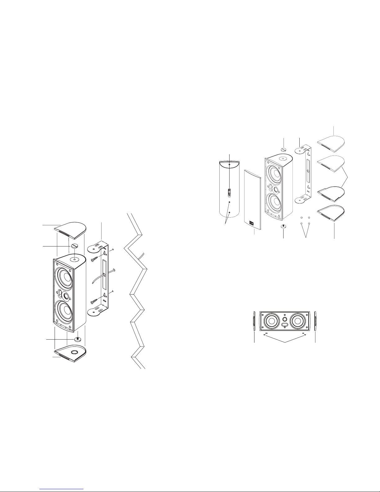
1. Input Terminals 5. Self Adhesive Cabinet Feet
2. Threaded Inserts 6. B-Type Bracket Mount End Cap
3. Brass Thumb Screws 7. A-Type Standard End Cap
4. Aluminum Bracket 8. Grille
MPP CONFIGURATION GUIDE
Center Channel
Remove the B-Type end caps, brass thumb screws and aluminum mounting bracket. Replace the brass
thumb screws in each end of the cabinet and snap A-Type end caps into place. Then simply place the
self adhesive cabinet feet in the appropriate locations to protect the MPP cabinet and whatever surface
that it will sit on.
Montage sur support
1. Retirez les enjoliveurs de type B, les vis moletées en laiton et le support de montage en aluminium.
2. Maintenez-le contre la surface de montage voulue. Veillez à laisser assez de place pour permettre le
serrage des vis moletées en laiton et la mise en place des enjoliveurs de type B.
Remarque : L’enceinte MPP peut être montée horizontalement ou verticalement, mais le type de
conception MTM utilisé pour cette enceinte répartit mieux le son dans toute la zone d’écoute avec
un montage vertical.
3. À l’aide d’un niveau à bulle ou d’un mètre à ruban, vérifiez que le support est d’équerre par rapport aux
surfaces proches.
4. Marquez les emplacements des trous de vis de montage du support.
5. Percez des trous-guides (si nécessaire) dans la surface de montage.
6. Faites passer le câble de l’enceinte par le trou central du support.
7. Fixez le support à la surface de montage.
Remarque : Les poids approximatifs des enceintes MPP sont les suivants : MPP410 – 1,4 kg ;
MPP420 – 2,0 kg ; MPP520 – 2,5 kg. Utilisez exclusivement des accessoires pouvant soutenir de
telles charges.
8. Glissez l’enceinte dans le support de montage et fixez-la à l’aide des deux vis moletées en laiton.
9. Réglez l’enceinte suivant l’orientation voulue et serrez les vis moletées.
10. Fixez les enjoliveurs de type B en insérant leur languette de montage dans l’encoche placée à l’arrière
de l’écran acoustique de l’enceinte. Puis enfoncez l’enjoliveur sur la vis moletée en laiton.
A-Type
Cap
A-Type
Cap
Self adhesive
Cabinet Feet
enjoliveur
type B
enjoliveur
type A
Vis moletées
en laiton
Support en
aluminium
Vis moletées
en laiton
213
Page 4

Bookshelf
Remove the B-Type end caps, brass thumb screws and aluminum mounting bracket. Replace the brass
thumb screws in each end of the cabinet and snap A-Type end caps into place. Then simply place the
self adhesive cabinet feet in the appropriate locations to protect the MPP cabinet and whatever surface
that it will sit on.
Floor Stand
Remove the B-Type end caps, brass thumb screws and aluminum mounting bracket. Replace the brass
thumb screws in the top of the cabinet and snap an A-Type end cap into place. Then simply mount the
MPP to the recommended Studio Tech SN-A stands using a 1/4-20 1” long hex head bolt. (Not Included)
Il suffit ensuite de mettre les pieds adhésifs d’enceinte aux emplacements prévus pour protéger l’enceinte
MPP et la surface sur laquelle elle sera posée.
Enceinte de bibliothèque
Retirez les enjoliveurs de type B, les vis moletées en laiton et le support de montage en aluminium.
Remettez les vis moletées en laiton à chaque extrémité de l’enceinte et enfoncez les enjoliveurs de type A.
Il suffit ensuite de mettre les pieds adhésifs d’enceinte aux emplacements prévus pour protéger l’enceinte
MPP et la surface sur laquelle elle sera posée.
Enceinte à piétement
Retirez les enjoliveurs de type B, les vis moletées en laiton et le support de montage en aluminium.
Remettez la vis moletée en laiton à extrémité supérieure de l’enceinte et enfoncez l’enjoliveur de type A.
Il suffit ensuite de monter l’enceinte MPP sur le socle recommandé Studio Tech SN-A à l’aide d’un boulon
1/4-20 à tête hexagonale de 25 mm de long (socle et boulon non fournis).
A-Type
Cap
A-Type
Cap
Self adhesive
Cabinet Feet
A-Type
Cap
Studio Tech
SN-A Stands
Recommended
1/4-20
1” Long Bolt
socle recommandé
Studio Tech SN-A
boulon 1/4-20,
25 mm de long
enjoliveur
type A
enjoliveur
type A
enjoliveur
type A
enjoliveur
type A
enjoliveur
type A
Pieds autocollants
d’enceinte
Pieds autocollants
d’enceinte
3 12
Page 5

FÉLICITATIONS
… pour votre achat de ces enceintes universelles MTX. Elles sont le fruit d’années de recherche et
développement poussés dans le domaine des techniques les plus évoluées de conception et d’étude
d’enceintes. Grâce à une technologie avancée et à la haute qualité de ses composants et circuits électro
niques, les enceintes MTX garantissent un niveau exceptionnel de performance et de valeur.
Ces enceintes ont été très soigneusement inspectées pendant et après leur fabrication afin d’assurer
le respect de toutes les normes de qualité. En cas de dommages dus au transport ou à la manutention,
veuillez contacter immédiatement le transporteur ou le détaillant. Merci d’avoir choisi MTX pour votre
équipement audio.
INTRODUCTION
La gamme MPP de MTX bénéficie probablement de la technologie d’enceinte la plus complète jamais
conçue. La souplesse incomparable de mise en œuvre ainsi offerte permet d’écouter de la musique pra
tiquement partout et dans toute configuration imaginable.
PEINTURE
Retirez le logo après avoir enlevé avec précaution son agrafe élastique derrière la grille. Masquez la zone
de l’écran acoustique du coffret jusqu’à la rainure de montage de la grille. Pratiquement tous les types
de peinture conviennent, mais une peinture émaillée ou laquée à pulvérisation et séchage rapide donne
les meilleurs résultats. Suivez toujours les recommandations d’application du fabricant de peinture afin
d’optimiser les résultats. Après avoir peint le coffret, la grille et les enjoliveurs éventuels, laissez la peinture
sécher complètement.
GUIDE DES PIÈCES MPP
A
B
6
7
5
3
8
2
3
4
7
1
1. Bornes d’entrée 5. Pieds autocollants d’enceinte
2. Douilles taraudées 6. Enjoliveur de support de montage type B
3. Vis moletées en laiton 7. Enjoliveur standard type A
4. Support en aluminium 8. Grille
GUIDE DE CONFIGURATION MPP
Enceinte de canal central
Retirez les enjoliveurs de type B, les vis moletées en laiton et le support de montage en aluminium.
Remettez les vis moletées en laiton à chaque extrémité de l’enceinte et enfoncez les enjoliveurs de type A.
Bracket Mounting
1. Remove the B-Type end caps, brass thumb screws and aluminum mounting bracket.
2. Hold the bracket up to the desired mounting surface. Being careful to leave enough space for tightening
the brass thumb screws and installing the B-Type end caps.
Note: Although the speaker can be mounted either horizontally or vertically, the MTM type of design used in the MPP will produce a more evenly distributed sound through out the listening area if
mounted vertically.
3. Use a level or measuring tape to insure that the bracket is square with its surroundings.
4. Mark the locations of the bracket mounting screw holes.
5. Drill pilot holes (if required) into the mounting surface.
6. Pull the speaker wire through the center hole in the bracket.
7. Attach the bracket to the mounting surface.
Note: The approximate weight for the MPP’s are, MPP410 - 3.0 lbs, MPP420 - 4.5 lbs., MPP520 - 5.5
lbs., use only hardware that will support this type of load.
8. Slide the cabinet into the mounting bracket and secure with the two brass thumb screws.
9. Adjust the cabinet for the desired angle and tighten the thumb screws.
10. Attach the B-Type end caps by inserting the cap mounting tab into the slot in the back of the speaker
baffle. Then snap the cap down onto the brass thumb screws.
B-Type
Cap
B-Type
Cap
Brass Thimb
Screw
Brass Thimb
Screw
Aluminum
Bracket
411
Page 6

WIRING
Connecting the speakers to your system
Though there are many sizes of speaker wire available. MTX recommends using 18 gauge or heavier
wire to connect your loudspeakers to your amplifier or receiver. Before cutting the speaker wire to the
proper lengths, be sure to leave an extra two or three feet of surplus wire, just in case you have to move
the components around. Using a wire cutter or sharp knife, strip off about half an inch of insulation from
both ends. Twist the exposed wires to make them easier to insert in the speaker terminals. Make sure that
you unplug your amplifier or receiver before proceeding any further.
When using the Multi-Purpose Plasma Speaker as a center channel or surround speaker follow the hookup directions included with your surround processor.
It is essential that you connect your two speakers “in phase”. To do so, first take note of the code used on
the speaker wire to differentiate between the two wires that run through it.
To wire your speakers in phase, make sure the positive (+) terminals on the back of your receiver are
connected with the red terminals on the back of your loudspeakers, and the negative (-) terminals on the
receiver are connected with the black terminals on the speakers (see diagram). Note that negative (-)
terminals on the receiver may also be marked “common” or “ground” (GND).
Be certain that no stray strands of wire cross from one terminal to another on either speaker or receiver.
This could result in a damaging short.
+
-
+
-
+
-
RED
BLACK
RED
BLACK
RED BLACK
LEFT RIGHT
MPP SET UP GUIDE
Home Theater
Typical Loudspeaker Placement
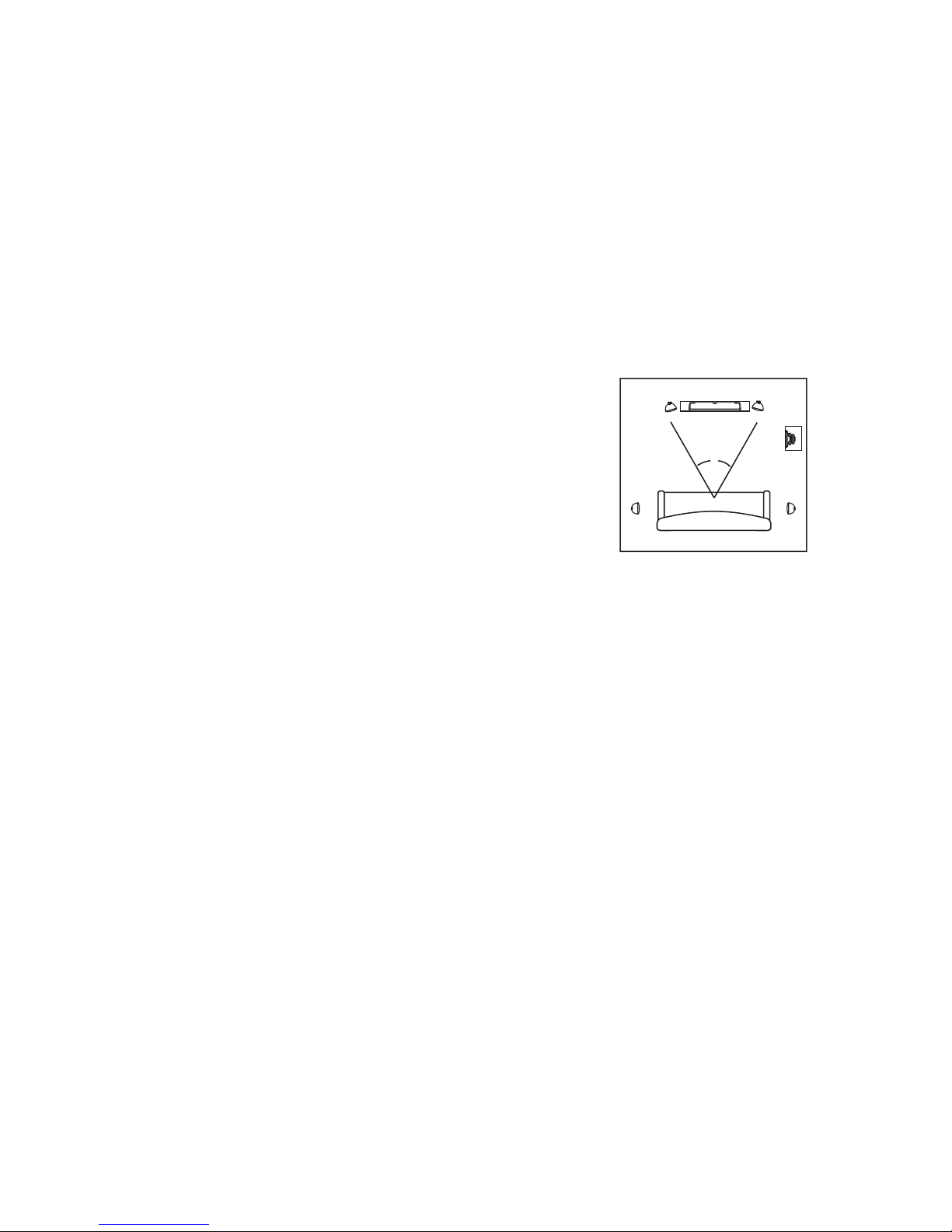
Figure 4 illustrates the most generally accepted speaker locations for a home theater system. Although
there are an infinite number of set up options using Figure 4 as a template will certainly provide a great
starting point. Experimentation with slightly different speaker locations may provide improved perfor
-
mance in your specific listening environment.
RIGHT
FRONT
LEFT
FRONT
45
LEFT
REAR
RIGHT
REAR
SUBWOOFER
(OPTIONAL)
LISTENING AREA
CENTER
FRONT
GUÍA DE CONFIGURACIÓN DEL MPP
Cine en casa
Colocación normal de los altavoces
La Figura ilustra la manera más generalmente aceptada de ubicar los altavoces en un sistema de cine en
casa. Aunque hay una serie infinita de opciones de configuración, usar la Figura 4 como plantilla da cier
tamente un magnífico punto de partida. Experimentar con posiciones de altavoz ligeramente diferentes
puede mejorar el rendimiento en el ambiente de audición específic
o.
RIGHT
FRONT
LEFT
FRONT
45
LEFT
REAR
RIGHT
REAR
SUBWOOFER
(OPTIONAL)
LISTENING AREA
CENTER
FRONT
Cine en casa
Altura de los altavoces frontales derecho, izquierdo y central
Altavoz de canal central: Centre el altavoz directamente encima o debajo del televisor y móntelo en la
pared (vea las instrucciones de montaje en la pared). Cuando se usa el soporte de montaje incluido, cada
MPP puede girar 60° (30° en cada dirección) para lograr la orientación óptima hacia el área de audición.
Altavoces frontales izquierdo y derecho: Los altavoces frontales izquierdo y derecho deben formar un
triángulo de 45° cuyo vértice esté en la posición central del oyente. Deben estar aproximadamente en
línea con el televisor y a la misma distancia del televisor. La distancia al televisor no es de importancia
crítica, aunque una mayor separación tiende a hacer que el sonido parezca más espacioso. Evite que
cualquiera de los dos altavoces quede a menos de 2 pies de la pared lateral. Colóquelos a la altura del
oído del oyente sentado, si es práctico. Cuando utilice el soporte de montaje suministrado, cada MPP se
puede girar 60° (30° en cada dirección) para obtener la mejor orientación hacia el área de audición.
Altavoces surround izquierdo y derecho: Usar los MPP como altavoces surround asegura la corre
spondencia acústica y cosmética con los altavoces frontales izquierdo, derecho y central. La mejor ubicación para los altavoces surround es en o contra las paredes laterales del área de audición en cualquier
punto, desde junto a la posición del oyente hasta aproximadamente 20° detrás. Móntelos por encima del
nivel del oído del oyente sentado (5 a 7 pies), pero evite colocarlos en o contra el cielo raso. Oriéntelos
derecho de un lado a otro de la sala, ligeramente hacia la pared de atrás para producir un sonido más
difuso, o hacia la posición del oyente para producir un sonido más directo. Cuando se usa el soporte de
montaje suministrado, cada MPP se puede girar 60° (30° en cada dirección).
Altavoces surround traseros: Si sus componentes electrónicos aceptan Dolby Digital EX, THX Sur
round EX o canal surround DTS-ES 7.1 ó 6.1, puede poner 1 ó 2 altavoces detrás del área de audición
como altavoces surround traseros. Tal como con los altavoces surround izquierdo y derecho, la posición
óptima es por encima del nivel del oído del oyente sentado. Si está usando sólo uno, el altavoz surround
trasero debe estar centrado detrás del área de audición; si está usando dos, deben estar bastante juntos.
Con este tipo de sistema, los surround normales izquierdo y derecho deben colocarse adyacentes al área
de audición en vez de detrás.
5 10
Page 7

Montaje del soporte
1. Quite las cofias tipo B, los tornillos manuales de latón y el soporte de aluminio.
2. Ponga el soporte a la altura deseada sobre la superficie de montaje, cuidando de dejar suficiente es
-
pacio para apretar los tornillos manuales de latón e instalar las cofias tipo B.
Nota. Aunque el altavoz se puede montar horizontal o verticalmente, el diseño MTM del MPP
produce un sonido distribuido de manera más uniforme en toda el área de audición si el altavoz
se monta verticalmente.
3. Utilice un nivel o una cinta de medir para asegurarse de que el soporte cuadre con lo que lo rodea.
4. Marque la posición de los agujeros de los tornillos de montaje del soporte.
5. Taladre agujeros piloto (si se requiere) en la superficie de montaje.
6. Jale el cable de altavoz a través del agujero central del soporte.
7. Fije el soporte en la superficie de montaje.
Nota. Los pesos aproximados de los MPP son los siguientes: MPP410, 3.0 lbs; MPP420, 4.5 lbs.;
MPP520, 5.5 lbs. Use sólo el equipo que soporte la carga correspondiente.
8. Ponga la caja en el soporte y asegúrela con dos tornillos manuales.
9 . Ajuste la caja según el ángulo deseado y apriete los tornillos manuales.
10. Ponga las cofias tipo B insertando la lengüeta de montaje de la cofia en la ranura que hay en la parte
de atrás del bafle del altavoz. Luego encaje la cofia sobre los tornillos manuales.
Home Theater
Left/Center/Right Front Speaker Height
Center-Channel Speaker: Center the speaker directly above or below your TV and mount it on the wall
(see wall mounting instructions). When using the supplied mounting bracket, each MPP can be rotated 60o
(30o in each direction) to obtain optimal directivity toward the listening area.
Front Left and Right Speakers: The front left and right speakers should form a 45
o
triangle using the
center seating position as the apex. They should also be approximately in line with your TV and equidistant
from it. The distance from the TV is not critical, though wide separation will tend to make the sound more
spacious. Avoid having either speaker closer than 2 feet to a side wall. Place them at seated ear height
if that is practical. When using the supplied mounting bracket, each MPP can be rotated 60
o
(30o in each
direction) to obtain optimal directivity toward the listening area.
Left and Right Surround Speakers: Using MPP’s as surround speakers ensures an acoustic and cos
-
metic match to the front left, right and center speakers. The best location for speakers employed as sur
round speakers is on or against the walls to the sides of the seating area, anywhere from adjacent to the
listening position to about 20
o
behind it. Mount them above the ear height of seated listeners (5’-7’ high)
but avoid placing them up against or on the ceiling. Aim them straight across the room or back slightly
toward the rear wall for a more diffuse sound or toward the listening position for a more direct sound. When
using the supplied mounting bracket, each MPP can be rotated 60
o
(30o in each direction).
Surround Back Speakers: If your electronics support Dolby Digital EX, THX Surround EX or DTS-ES 7.1
or 6.1 channel surround, you can place one or two speakers behind the seating area to serve as surround
back speakers. As with the left and right surrounds, the optimum location is above seated ear level. If you
are using just one back surround speaker, it should be centered behind the listening area; if you are using
two, they should be spaced fairly close together. With this type of system, the regular left and right sur
-
rounds should be located adjacent to the seating area rather than behind it.
Cofia
Tipo B
Cofia
Tipo B
Tornillos manuales
de latón
Tornillos manuales
de latón
Soporte de
aluminio
69
Page 8

FELICITACIONES
...por su compra de altavoces multipropósito MTX. Sus nuevos altavoces representan muchos años de
minuciosa investigación y desarrollo en las más modernas técnicas de diseño e ingeniería de altavoces.
Los altavoces MTX le garantizan rendimiento y valor excepcionales con su avanzada tecnología y sus
sistemas y componentes electrónicos de alta calidad.
Sus altavoces fueron cuidadosamente examinados durante y después de la fabricación para satisfacer o
superar todos los estándares de calidad. Si ha habido daños como resultado del transporte y la manipulación, comuníquese inmediatamente con el transportista o el distribuidor. Gracias por seleccionar MTX
cuando hizo su compra de equipo de audio.
INTRODUCCIÓN
Es posible que la serie MTX MPP tenga el diseño de altavoz más completo jamás concebido. La inigualable flexibilidad de aplicación que este diseño permite le da a usted la libertad de escuchar su música casi
en cualquier lugar y en casi cualquier configuración posible.
PINTURA
Quite cuidadosamente el sujetador de resorte de la parte de atrás del logotipo de la rejilla y quite el logotipo. Enmascare el área del bafle de la caja del altavoz hasta la ranura de montaje de la rejilla. Se puede
usar casi cualquier tipo de pintura, pero los mejores resultados se obtienen con un esmalte de secado
rápido o una pintura aerosol de laca. Para obtener los mejores resultados, siga siempre las recomenda
ciones del fabricante a fin de lograr una aplicación correcta. Después de pintar la caja, la rejilla y las tapas
de extremo que corresponden, deje que la pintura se seque completamente.
GUÍA DE PIEZAS DEL MPP
A
B
6
7
5
3
8
2
3
4
7
1
1. Terminales de entrada 5. Patas autoadhesivas de la caja
2. Insertos roscados 6. Cofia de montaje de soporte tipo B
3. Tornillos manuales de latón 7. Cofia estándar tipo A
4. Soporte de aluminio 8. Rejilla
GUÍA DE CONFIGURACIÓN DEL MPP
Altavoz de canal central
Quite las cofias tipo B, los tornillos manuales de latón y el soporte de aluminio. Vuelva a poner los tornillos
manuales de latón en los extremos de la caja y encaje las cofias tipo A en posición. Luego simplemente
ponga las patas a
utoadhesivas de la caja en los lugares apropiados para proteger la caja del MPP y la
superficie sobre la cual va a descansar.
Altavoz de estantería
Quite las cofias tipo B, los tornillos manuales de latón y el soporte de aluminio. Vuelva a poner los tornillos
manuales de latón en los extremos de la caja y encaje las cofias tipo A en posición. Luego simplemente
ponga las patas autoadhesivas de la caja en los lugares apropiados para proteger la caja del MPP y la
superficie sobre la cual va a descansar.
Altavoz de piso
Quite las cofias tipo B, los tornillos manuales de latón y el soporte de aluminio. Vuelva a poner los tornillos
manuales de latón en la parte de arriba de la caja y encaje las cofias tipo A en posición. Luego, simplemente monte el MPP en el pedestal recomendado Studio Tech SN-A con un perno de 1/4-20 de cabeza
hexagonal y 1 plg. de longitud (no se incluye).
Cofia
Tipo A
Cofia
Tipo A
Patas autoadhesivas
de la caja
Patas autoadhesivas
de la caja
Cofia
Tipo A
Cofia
Tipo A
Cofia
Tipo A
1 plg. longitud
perno
Pedestal recomendado
Studio Tech SN-A
7 8
 Loading...