

Page 1
MODEL MP52B/MODEL MP52W
Owners Manual
Page 2

CONGRATULATIONS
...on your purchase of MTX multi-purpose loudspeakers.Your new
loudspeakers represent years of thorough research and development in
the most modern techniques of speaker design and engineering. Using
advanced technology and high quality electronics and components,
MTX loudspeakers assure you of exceptional performance and value.
Your speakers were examined very carefully during and after
manufacturing to assure all quality standards were met or exceeded. If
damage as a result of shipping and handling has occurred, please
contact the shipper or your dealer immediately.
Thank you for selecting MTX when you made your audio equipment
purchase.
TABLE OF CONTENTS
Introduction . . . . . . . . . . . . . . . . . . . . . . . . . . . . . . . . . .2
Parts Guide . . . . . . . . . . . . . . . . . . . . . . . . . . . . . . . . . .3
Center Channel Configuration . . . . . . . . . . . . . . . . . . . .4
Bookshelf Configuration . . . . . . . . . . . . . . . . . . . . . . . . .5
Floor Stand Configuration . . . . . . . . . . . . . . . . . . . . . . .6
Bracket Mount Configuration . . . . . . . . . . . . . . . . . . . .7,8
Painting Guide . . . . . . . . . . . . . . . . . . . . . . . . . . . . . . . .9
Grill Assembly . . . . . . . . . . . . . . . . . . . . . . . . . . . . . . . .9
Wiring Guide . . . . . . . . . . . . . . . . . . . . . . . . . . . . . . . .10
Set Up Guide, Home Theater . . . . . . . . . . . . . . . . .11,12
Specifications . . . . . . . . . . . . . . . . . . . . . . . . . . . . . . . .13
1
Page 3

INTRODUCTION
About the MP52 Multi Purpose Speaker
The MTX MP52 may be the most comprehensive
loudspeaker design ever conceived. The unparalleled
application flexibility afforded by this design gives you the
freedom to listen to music almost anywhere and in just
about any possible configuration.
Features
•1” PEF Dome Tweeter
Extended high frequency response and well controlled off
axis response are achieved by using a hot pressed high
performance PEF dome tweeter. This particular design
offers the “sweet” sound of a soft dome tweeter while
incorporating durable, weather resistant materials. The
tweeter is also magnetically shielded to minimize color
distortion of your TV when used as a home theater system
center channel or front main speaker.
•Dual 5” Woofers
The mineral filled polypropylene cones and butyl rubber
surrounds of the MP52 are combined with a computer
optimized magnetically shielded motor structure and long
wind voice coils to provide extended low bass response.
The MTM design allows the dual woofers to mesh perfectly
with the dome tweeter to provide excellent frequency
response characteristics, both on and off axis, across the
majority of the audible frequency spectrum.
•Weather Resistant Design
All of the material used in the construction of the Model
MP52 were chosen for their environmental stability as well
as their sonic characteristics.
2
Page 4
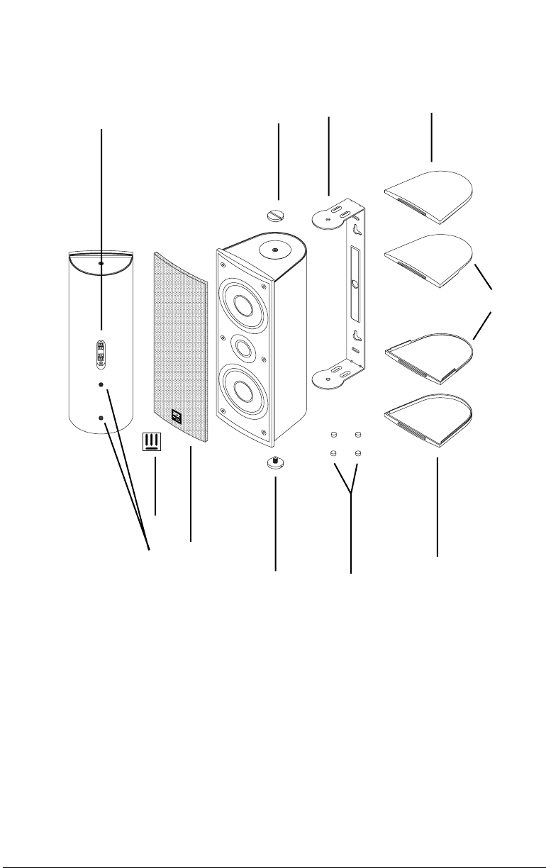
MP52 PARTS GUIDE
1
3
4
7
6
B
A
9
8
2
3
1. Input Terminals
2. Threaded Inserts
3. Brass Thumb Screws
4. Aluminum Bracket
5. Self Adhesive Cabinet Feet
6. B-Type Bracket Mount End Cap
7. A-Type Standard End Cap
8. Grill
9. Grill Adhesive
3
7
5
Page 5
MP52 CONFIGURATION GUIDE
CENTER CHANNEL
Remove the B-Type end caps, brass thumb screws, and
aluminum mounting bracket. Replace the brass thumb
screws in each end of the cabinet and snap A-Type end
caps into place. Then simply place the self adhesive cabinet
feet in the appropriate locations to protect the MP52 cabinet
and whatever surface that it will sit on.
A-TYPE
CAP
SELF ADHESIVE
CABINET FEET
A-TYPE
CAP
4
Page 6

MP52 CONFIGURATION GUIDE
BOOKSHELF
Remove the B-Style end caps, brass thumb screws, and
aluminum mounting bracket. Replace the brass thumb
screws in each end of the cabinet and snap A-Type end
caps into place. Then simply place the self adhesive cabinet
feet in the appropriate locations to protect the MP52 cabinet
and whatever surface that it will sit on.
A-TYPE
CAP
A-TYPE
CAP
SELF ADHESIVE
5
CABINET FEET
Page 7

MP52 CONFIGURATION GUIDE
FLOOR STAND
Remove the B-Type end caps, brass thumb screws, and
aluminum mounting bracket. Replace the brass thumb
screws in the top of the cabinet and snap an A-Type end
cap into place. Then simply mount the MP52 to the
recommended Studio Tech SN-A stands using a 1/4-20 1”
long hex head bolt. (Not Included)
A-TYPE
CAP
1/4-20
1” LONG
BOLT
STUDIO TECH
SN-A STANDS
RECOMMENDED
6
Page 8

MP52 CONFIGURATION GUIDE
BRACKET MOUNTING
ALUMINUM
B-STYLE
CAP
BRASS
THUMB
SCREW
BRACKET
BRASS
THUMB
SCREW
B-STYLE
CAP
7
B
Page 9

MP52 CONFIGURATION GUIDE
BRACKET MOUNTING
1) Remove the B-Type end caps, brass thumb screws, and
aluminum mounting bracket.
2) Hold the bracket up to the desired mounting surface.
Being careful to leave enough space for tightening the brass
thumb screws and installing the B-Type end caps.
Please Note: Although the speaker can be mounted either
horizontally or vertically, the MTM type of design used in the
MP52 will produce a more evenly distributed sound through
out the listening area if mounted vertically.
3 Use a level or measuring tape to insure that the bracket is
square with its surroundings.
4) Mark the locations of the bracket mounting screw holes.
5) Drill pilot holes (if required) into the mounting surface.
6) Pull the speaker wire through the center hole in the
bracket.
7) Attach the bracket to the mounting surface.
Please Note:
The MP52 weighs approximately 9.5 pounds, use only
hardware that will support this type of load.
8) Slide the MP52 cabinet into the mounting bracket and
secure with the two brass thumb screws.
9) Adjust the MP52 cabinet for the desired angle and
tighten the thumb screws.
10) Attach the B-Type end caps by inserting the cap
mounting tab into the slot in the back of the speaker baffle.
Then snap the cap down onto the brass thumb screws.
8
Page 10

PAINTING
Carefully remove the spring clip on the back of the grill logo
and remove the logo. Mask the baffle area of the speaker
cabinet out to the grill mounting groove. If you are going to
mount the MP52 using the supplied wall bracket it is best to
also mask off the foam rubber bracket gaskets at the top
and bottom of the speaker cabinet. Almost any type of paint
can be used but best results will be had using a quick
drying enamel or lacquer spray paint. For best results
always follow the paint manufacturers recommendations for
proper application. After painting the cabinet, grill and
applicable end caps allow the paint to dry thoroughly.
GRILL ASSEMBLY
Place the four grill adhesive strips in the groove located at
the outer rim of the baffle. Carefully snap the grill into place
and rotate the logo for proper orientation.
9
Page 11

WIRING
Connecting the Speakers to Your System
Though there are many sizes of speaker wire available.
MTX recommends using 18 gauge or heavier wire to
connect your loudspeakers to your amplifier or receiver.
Before cutting the speaker wire to the proper lengths, be
sure to leave an extra two or three feet of surplus wire, just
in case you have to move the components around. Using a
wire cutter or sharp knife, strip off about half an inch of
insulation from both ends. Twist the exposed wires to make
them easier to insert in the speaker terminals. Make sure
that you unplug your amplifier or receiver before proceeding
any further.
When using the MP52 as a center channel or surround
speaker follow the hook-up directions included with your
surround processor.
It is essential that you connect your two speakers “in
phase”. To do so, first take note of the code used on the
speaker wire to differentiate between the two wires that run
through it.
To wire your speakers in phase, make sure the positive (+)
terminals on the back of your receiver are connected with
the red terminals on the back of your loudspeakers, and the
negative (-) terminals on the receiver are connected with
the black terminals on the speakers (see diagram). Note
that negative (-) terminals on the receiver may also be
marked “common” or “ground” (GND).
Be certain that no stray strands of wire cross from one
terminal to another on either speaker or receiver. This could
result in a damaging short.
RED
BLACK
RED BLACK
LEFT RIGHT
-
+
-
-
+
RED
+
BLACK
10
Page 12

MP52 SET UP GUIDE
HOME THEATER
Typical Loudspeaker Placement
Figure 1 illustrates the most generally accepted speaker
locations for a home theater system. Although there are an
infinite number of set up options using Figure 1 as a
template will certainly provide a great starting point.
Experimentation with slightly different speaker locations may
provide improved performance in your specific listening
environment.
The front left and right speakers should form a 45 degree
triangle using the center seating position as the apex.
The surround speakers should be placed beside the
listening area, and pointed towards each other. It is also
recommended that the speakers be 2-3 feet above the
listeners head.
CENTER
LEFT
FRONT
FRONT
RIGHT
FRONT
11
45
LEFT
REAR
LISTENING AREA
Figure 1 Typical loudspeaker placement in a home theater system.
SUBWOOFER
(OPTIONAL)
RIGHT
REAR
Page 13

MP52 SET UP GUIDE
HOME THEATER
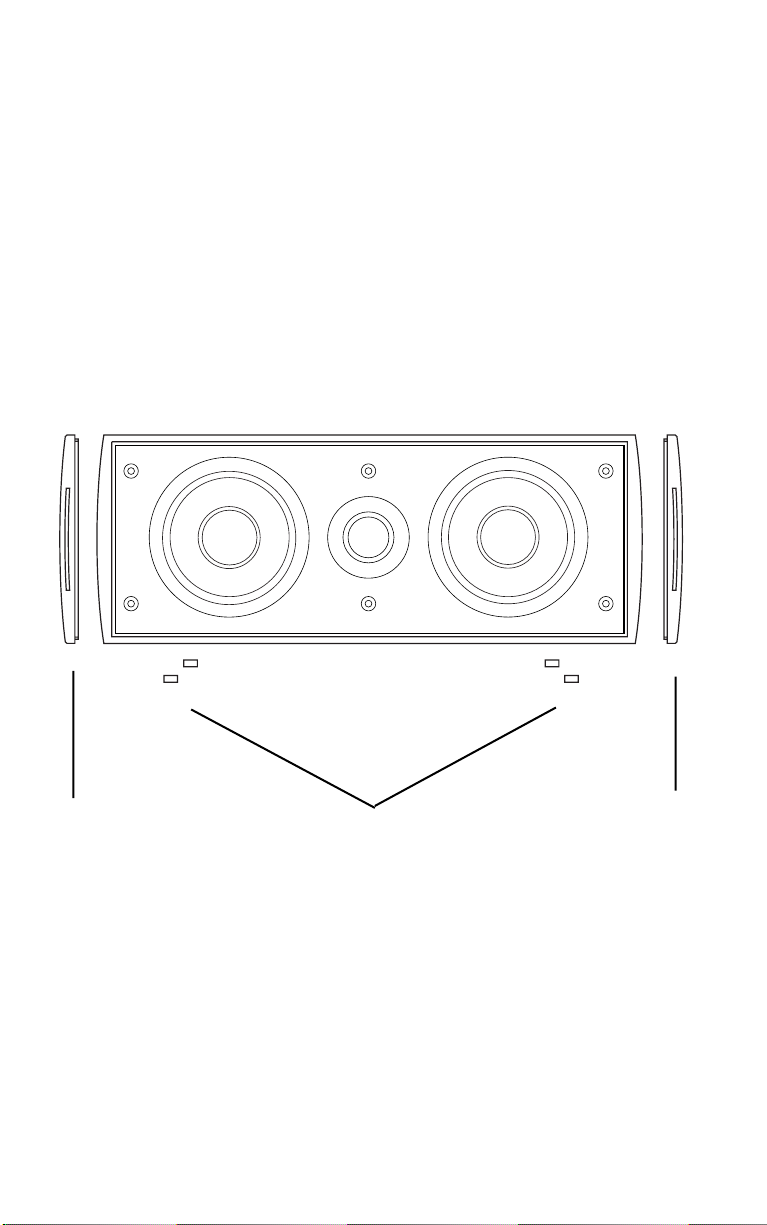
Left/Center/Right Front Speaker Height
One of the most Important parameters for the
left/center/right/front speakers in a home theater system is
height. Figure 2 shows the ideal arrangement of the
speakers in relation to the viewing screen: all three
speakers are aligned on the same horizontal plane. This
establishes a firm image height when special audio effects
are panned from one side to the other, such as a speeding
car moving across the screen. When a large discontinuity
occurs between the heights of the center front channel and
the left/right front speakers, as depicted in Figure 3, the
visual image of the moving object becomes confused and
somewhat unnatural due to shifts in image height.
Figure 2 Proper placement of left/center/right front speakers.
Figure 3 Improper placement of left/center/right front speakers.
12
Page 14

SPECIFICATIONS
Frequency Response
Impedance
Power Handling
Total Power Handling
Sensitivity
Woofer
Tweeter
Dimensions
90-20kHz
8 Ohms
75 Watts RMS
300 Watts
86dB @ 1W/1m
5” Shielded
1” Shielded PEF Dome
14.250”H x 6.625”W x 6.000”D
13
Specifications subject to change without notice.
 Loading...