

Page 1

MTX.COM
OWNER’S MANUAL
CANAM-10
CAN-AM
®
AMPLIFIED SUBWOOFER ENCLOSURE
Page 2

MTX.COM
2
IMPORTANT NOTICE
If you have any questions regarding wire routing in a vehicle, please contact MTX Technical Support
at 1-800-225-5689.
When connecting power and ground wires ensure that the red power wire is fused at the point
where it is connected to the vehicle’s battery. Failure to do so can result in damage to the vehicle if a
short circuit develops between the vehicle connection point and the product.
PRODUCT INFORMATION
Model #
Serial #
Dealer’s Name
Date of Purchase
IN THE BOX
• CANAM-10 Amplied Subwoofer Enclosure
• EBC and EBC Extension Wire
• Mounting Hardware
(2) M6-1.0x25 Hex Bolts
(2) M6-1.0 Nylon Locknuts
(4) M6 Flat Washers
(2) ST6.3 25mm Self-tapping Screws
(4) Torx Pan Head 18mm Self-tapping Screws
ADDITIONAL ACCESSORIES NEEDED AND NOT INCLUDED
MTX recommends using StreetWires PS1K-10 amp kit which includes the following:
• Power and Ground Wire to Run to the Battery
• 20A ATC Fuse Holder
• Accessory Connection Wire
• RCA Cables to Connect to the Source
INSTALLATION TOOLS
The following is a list of suggested tools needed for installation:
• Torx - T27
• Torx - T25
• Torx - T20
• Torx - T15
• 10mm Socket Wrench
• 5⁄16" Drill Bit
• 1⁄8" Drill Bit
INTRODUCTION
Thank you for purchasing the MTX Audio amplied subwoofer enclosure designed for the Can-Am®
Commander and Maverick. The easy to install subwoofer is the perfect direct t bass solution for
your Can-Am® vehicle. Congratulations and enjoy the ultimate audio experience with MTX!
FITS THE FOLLOWING VEHICLES
• Commander - 2 and 4 Seats (2012 and Up)
• Maverick - 2 and 4 Seats (2012 and Up)
Page 3

MTX.COM
3
FEATURES
• 10" All-Weather Amplied Subwoofer Enclosure
• Integrated 250-Watt RMS / 500-Watt Peak Power Amplier
• Integrated Power and Ground Connections
• Low Level Input with External Gain Control
• Dash Mount Bass Control Knob (Included)
• Mounts Underneath Dashboard (Passenger Side) - Direct Fit
SPECIFICATIONS
• RMS Power Handling: 250-Watts
• Peak Power Handling: 500-Watts
• Frequency Response: 34Hz - 130Hz
Page 4
MTX.COM
4
INSTALLATION
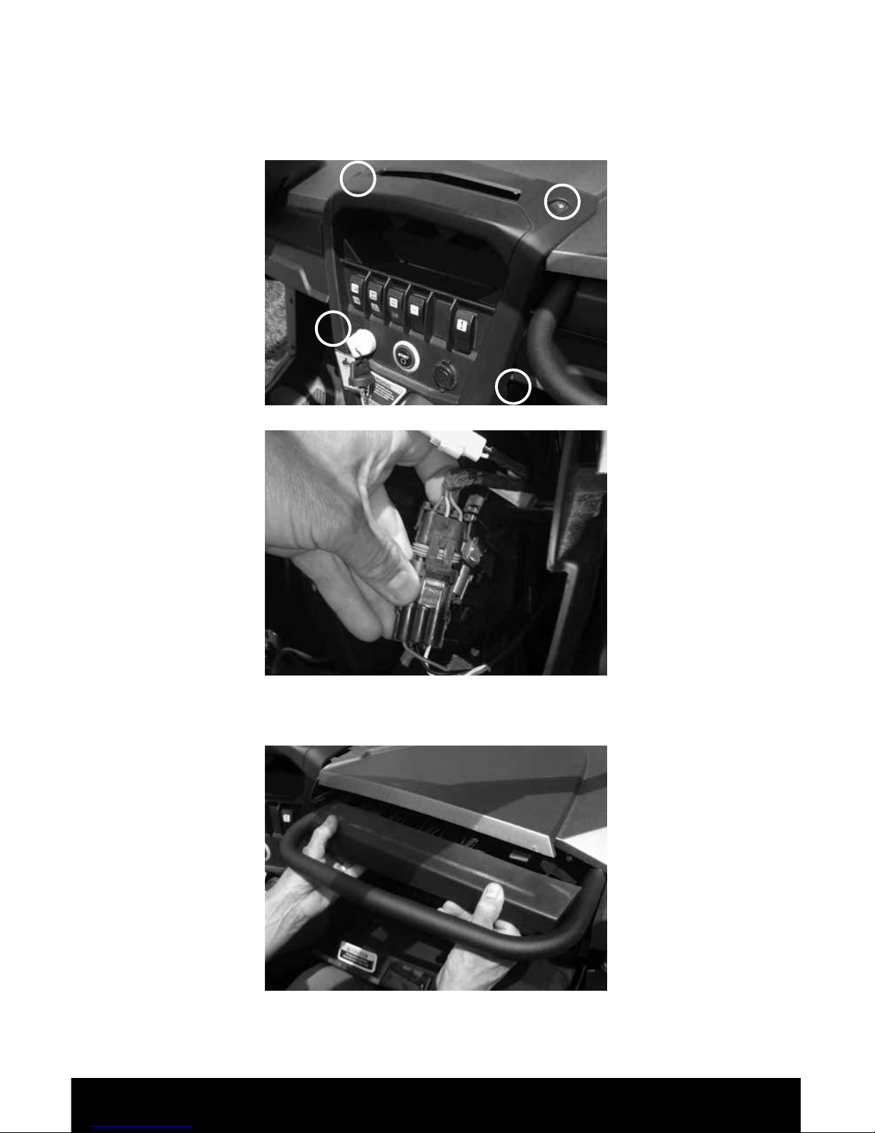
Step 1 - Using a T25 Torx, remove the center switch bezel by removing the two top screws and the
two plastic retainer pins from both the left and right sides. Open the glove box and slide the dash
bezel towards you. Place on top of dash out of the way. Unplug the winch controller if equipped.
Step 2 - Remove the trim piece above the glove box by gripping it on both sides and rmly pulling
straight back towards you.
Page 5

MTX.COM
5
Step 3 - Remove the 10mm hex bolts that hold the glove box in place. These are located in the upper
left and upper right area of the glove box.
Step 4 - To remove the glove box, pull straight back towards the passenger seat. If equipped,
carefully remove the winch plug from behind the center switch bezel. Be careful not to damage the
wire and connector when removing it.
Step 5 - Using a T27 Torx, remove the bottom two bolts and nuts from the passenger side inner fender.
The top one can be left in place.
Page 6

MTX.COM
6
Step 6 - Unscrew the woofer from the enclosure using a T20 Torx and disconnect the speaker wire
going to the terminal.
Step 7 - Place the enclosure in the vehicle with the enclosure angled as shown. Push the narrow part
of enclosure up under the dash and rotate the enclosure up and into the vehicle, it will be a snug t.
Step 8 - When correctly installed, the enclosure will t as shown.
Step 9 - Feed the wiring from the enclosure behind the center switch bezel.
Page 7

MTX.COM
7
Step 10 - Use a
5
⁄16" drill bit to drill through the rewall from inside the enclosure using the two existing
holes behind the subwoofer mounting hole. Remove the plastic shavings created by the drilling
process from inside the enclosure.
Step 11 - Bolt the enclosure in place using the supplied M6 hardware, tighten down until secure.
Step 12 - Using a
1
⁄8" drill bit, drill through the inner fender holes into the enclosure. Using the supplied
screws, secure the enclosure into place through the fender holes. Do not over-tighten the screws.
Step 13 - Connect the internal speaker wires to the subwoofer, red to positive. Screw the subwoofer
in place using the four machine screws that were removed earlier (Step 6). Using a T15 Torx, nish
securing the woofer in place using the four supplied self-tapping screws in the remaining mounting
holes.
Step 14 - Now that the enclosure is securely tightened in place, the power and signal wires need to
be connected to the battery and signal source.
• The Red wire should be connected directly to the battery’s positive terminal and fused with a
20A fuse.
• The Black wire should be directly connected to the battery’s negative terminal.
• The Blue wire should be connected to the ACC / Key Turn On.
Step 15 - Connect the RCA inputs to the signal source of your choice
Step 16 - Turn the unit on and check to make sure everything works. Set the gain using the gain pot
that is attached to the orange/grey wires. Set the gain to the bass level desired.
Page 8

MTX.COM
8
Step 17 - The included EBC can be connected and mounted to a desired location to allow easy trim
adjustment of the bass level after the gain has been set.
Step 18 - Replace all the parts and screws that have been removed to return the vehicle back to its
completely assembled state.
Page 9

MTX.COM
9
NOTES:
Page 10

MTX.COM
10
NOTES:
Page 11

MTX.COM
11
NOTES:
Page 12

MTX.COM
12
© 2016 Mitek Corporation. All rights reserved. MTX, Mud Nation, and Let’s Do Something Dirty are trademarks
of Mitek Corporation. All other trademarks are property of their respective owners. Designed and Engineered in
the U.S.A.
Due to continual product development, all specications are subject to change without notice.
MTX Audio, 4545 East Baseline Rd. Phoenix, AZ 85042 U.S.A. 1-800-225-5689
MTX005506 RevA 8/16 • 21A10526 • AW0015342
 Loading...