

Page 1
21A6529
1 Mitek Plaza
Winslow, IL 61089
815-367-3000
800-225-5689
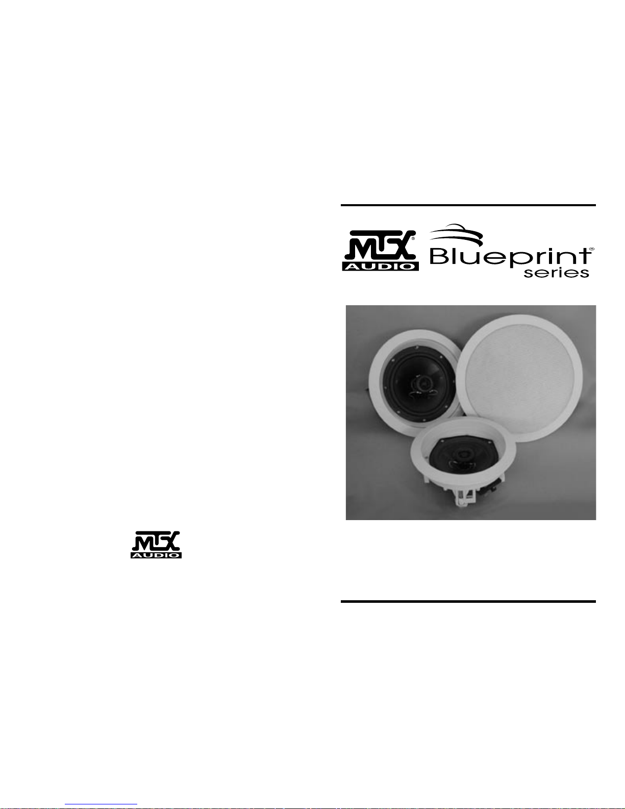
MODEL 512C/ MODEL 612C
and MODEL 812C
OWNER'S MANUAL
Page 2

CONGRATULATIONS
We appreciate your choice of MTX In-Ceiling Speakers. Properly installed and
operated, MTX In-Ceiling Speakers should provide years of worry-free listening
pleasure. It’s important that you follow each step in this guide carefully to insure
proper installation.
SPECIFICATIONS MODEL 512C MODEL 612C MODEL 812C
Frequency Response 72Hz-20kHz 50Hz-20kHz 40Hz-20kHz
±3dB ±3dB ±3dB
Impedance 8 ohms nominal 8 ohms nominal 8 ohms nominal
Power Handling 30 Watts RMS 35 Watts RMS 45 Watts RMS
60 Watts Peak 70 Watts Peak 90 Watts Peak
Music Music Music
Sensitivity (1W/1m) 85dB 85dB 85dB
Woofer Diameter 5-1/4” 6-1/2” 8”
Tweeter 1/2" 1/2" 1/2"
Balanced Dome Balanced Dome Balanced Dome
Mounting Depth 3-5/16” 3-1/8” 3-3/4”
Baffle Diameter 7-3/4” 9” 10-3/4”
PAINTING YOUR MTX IN-CEILING SPEAKERS
MTX In-Ceiling Speakers are designed to accept all types of interior and exterior
paints. Spray or roller application should provide excellent results. A paint shield
is included with all MTX In-Ceiling Speakers speakers to protect the speakers
during the painting process.
MTX WARRANTY INFORMATION
All MTX In-Ceiling Speakers purchased in the United States from an authorized MTX
dealer are guaranteed against defects in material and workmanship for a period ten
years from the date purchased by the end user, and limited to the original retail purchaser of the product.
MTX disclaims any liability for other incurred damages resulting from product defects.
Any expenses incurred in the removal and reinstallation of product is not covered by
this warranty. MTX's total liability will not exceed the purchase price of the product.
This warranty is valid in the United States only.
Proof of purchase is required when requesting service, so please retain your sales
receipt and take a moment to register your warranty on line at www.mtx.com.
Page 3

LOUDSPEAKER PLACEMENT
MTX In-Ceiling Speakers are designed to work within any interior decorating
scheme. They can be installed in virtually any location where flush mounting is
possible. To maximize their sound performance however certain guidelines should
be followed. For the best stereo reproduction the two loudspeakers should be
placed an equal distance from your listening position and separated so that the
angle between them, at the listening position, is between 40 and 60 degrees.
MODEL 625W
6-1/2” Two-Way In-Wall Speaker
25mm Soft Dome Swivel Tweeter
Impedance: 8 ohms nominal
Sensitivity: 85dB
55W RMS/110W Peak Music
Frequency Response: 48Hz-20kHz
12”H x 8 5/8”W x 3 1/4”D
MONITOR6
6-1/2” Two-Way Home Loudspeaker
19mm Dome Tweeter
Impedance: 8 ohms nominal
Sensitivity: 89dB
100W RMS/200W Peak Music
Frequency Response: 55Hz-20kHz
12 3/4”H x 7 1/2”W x 8 1/2”D
MONITOR10
10” Three-Way Home Loudspeaker
19mm Dome Tweeter
Impedance: 8 ohms nominal
Sensitivity: 92dB
200W RMS/400W Peak Music
Frequency Response: 30Hz-20kHz
31 7/16”H x 11 1/8”W x 14 5/16”D
MODEL 825W
8” Two-Way In-Wall Speaker
25mm Soft Dome Swivel Tweeter
Impedance: 8 ohms nominal
Sensitivity: 86dB
60W RMS/120W Peak Music
Frequency Response: 36Hz-20kHz
14”H x 10”W x 3-1/2”D
MONITOR6C
6-1/2” Center Channel Loudspeaker
19mm Dome Tweeter
Impedance: 8 ohms nominal
Sensitivity: 92dB
100W RMS/150W Peak Music
Frequency Response: 60Hz-20kHz
7 1/2”H x 17 5/8”W x 8”D
MONITOR12
12” Three-Way Home Loudspeaker
19mm Dome Tweeter
Impedance: 8 ohms nominal
Sensitivity: 94dB
250W RMS/500W Peak Music
Frequency Response: 25Hz-20kHz
35”H x 13 1/8”W x 16 1/16”D
OTHER PRODUCTS FROM MTX
In-Wall Loudspeakers
Home Loudspeakers
TECHNICAL ASSISTANCE
For additional technical assistance you can visit our website at www.mtx.com.
Otherwise, our technical service representatives can be reached by phone: 1-800CALL-MTX or by email: technical@mtx.com.
Page 4

STEP 1
Using a stud finder (available at low cost at most hardware stores) or other accurate method, locate center point between two joists and mark. Using template
provided, trace hole pattern on surface of ceiling
STEP 2
Using a sabre saw, keyhole saw or very sharp utility knife, cut hole in wall, following traced pattern.
STEP 3
Run loudspeaker wires to sound source location. There are several methods you
can use to accomplish wiring, depending on the construction characteristics of the
room or house. You can add a professional touch to your installation by using a
speaker terminal plate at the source location. Leave sufficient amount of wire at
speaker location (8 to 10 inches) to complete connection.
STEP 4
Attach loudspeaker wires to speaker terminals, observing correct polarity, and
position speaker frame up into cutout. Be careful not to pinch wires in the process.
STEP 5
Carefully tighten the four mounting screws. This will cause the mounting wings to
rotate out behind the mounting surface and secure the speaker in place.
STEP 6
After the speaker panel is secured tightly, test for sound. When you are satisfied
the speaker is operational, affix grill. As the MODEL 612C and MODEL 812C
grills are designed for a snug fit, you’ll need to position one edge into slot first,
and press or squeeze around perimeter of grill, while pushing leading edges into
grill slot. The MODEL 512C grill can be installed into the speaker frame for either
a standard flush mount cosmetic appearance or a recessed look similar to coilex
type of light fixture. After deciding which look is preferred press the grill into the
frame until the leading edge is flush.
 Loading...