

Page 1

1330-X02 Printer
Operator’s Manual
P/N 701333-004
Page 2
ELUDEHCSNOISIVER/EUSSI
stnemmoC.oN.veRetaD
esaeleRlaitinI100-33310739/13/01
etadpUlacinhceT
eussieRetelpmoC
etadpUlacinhceT
etadpUlacinhceT
eussieRetelpmoC
eussieRetelpmoC
IBM is a registered trademark of IBM Corporation.
602157100-
49/13/30
200-333107
100-602157
100-396657
300-333107
400-333107
49/01/60
49/51/90
49/02/21
69/20/20
99/11/60
© Copyright 1993, 1994, 1996 by MTX Corporation
ii 701333-004
Page 3
This equipment complies with FCC regulations for EMI.
WARNING!
This equipment generates, uses, and can radiate radio
frequency energy, and, if not installed and used in accordance with the manual, may cause interference to radio
communications. It has been tested and found to comply
with the limits for a Class A computing device pursuant to
Subpart J of Part 15 of FCC Rules, which are designed to
provide reasonable protection against such interference
when operated in a commercial envir onment. Operation of
this equipment in a residential area is likely to cause interference, in which case users, at their own e xpense, will be
required to take whatever measures may be necessary to
correct the interference.
701333-004 iii
Page 4

Table of Contents
Page
Chapter 1. Introduction ............................................................................................1-1
Interfacing with the 1330 ................................................................................1-2
A-Coax Attachment ....................................................................................1- 2
ASCII Attachment ......................................................................................1-3
Standard Features............................................................................................1-3
Character Codes .........................................................................................1-3
Color...........................................................................................................1-4
Paper Handling ...........................................................................................1-4
Print Qualities.............................................................................................1-4
Multiple Copies ..........................................................................................1-4
3270 Languages..........................................................................................1-4
Screen Sizes ...............................................................................................1-4
Self-Diagnostic T esting ..............................................................................1-5
Audible Alarm ............................................................................................1-5
Programmed Symbols ................................................................................1-5
IPDS ...........................................................................................................1-5
Optional Features............................................................................................1-5
Memory ......................................................................................................1-5
Continuous Forms Module .........................................................................1-5
Forms Handler Module...............................................................................1-6
Printer Pedestal Stand.................................................................................1-6
Forms Stand................................................................................................1-6
Related Manuals .............................................................................................1-6
Chapter 2. Preparing to Operate the 1330 ................................................................2-1
Inspecting the Package....................................................................................2-1
Unpacking the Printer .....................................................................................2-1
Installation Preparation ...................................................................................2-3
Installing the Ribbon Cartridge.......................................................................2-4
Ordering Ribbons .......................................................................................2-4
Installing a Shifting Ribbon........................................................................2-4
Installing a Nonshifting Ribbon .................................................................2-7
Connecting the Printer to a Power Source ......................................................2-8
Power Cable Requirements ........................................................................2-8
Connecting the Coax Cable ............................................................................2-9
Connecting a Parallel or Serial Cable ...........................................................2-10
Connecting a Parallel Cable .....................................................................2-10
Connecting a Serial Cable ........................................................................2-10
Powering on the 1330 ...................................................................................2-11
Forms Specifications.....................................................................................2-11
Installing the Forms – Continuous Forms Module........................................2-17
Setting the Platen Gap Lever ....................................................................2-20
Installing the Forms Handler Module ...........................................................2-21
Installing Forms Using the DOD Option..................................................2-21
Installing Forms Using the DID Option ...................................................2-23
Chapter 3. Operator Control Panel...........................................................................3-1
The Status Display..........................................................................................3- 1
Cu ...............................................................................................................3-2
S/C/A..........................................................................................................3-2
701333-004 v
Page 5

Table of Contents
The Keypad.....................................................................................................3-3
Chapter 4. Configuring the 1330 in 3270 Mode ........................................................4-1
Configuration Procedure.................................................................................4-1
The Configuration Options .............................................................................4-5
Page
Operating Mode..........................................................................................3-2
Form Device ...............................................................................................3-2
Emulation Mode .........................................................................................3-2
Datastream Mode/Interface T ype................................................................3-3
Status Message ...........................................................................................3-3
Key Functions.............................................................................................3-3
Using the Keys ...........................................................................................4-1
Getting into the Menu Mode ......................................................................4-1
Scrolling Through Menu Selections ...........................................................4-2
Selecting a Menu Option ............................................................................4-4
Leaving Menu Mode ..................................................................................4-4
100 Page Format.........................................................................................4-5
200 Font & Print Quality ............................................................................4-8
300 Compatibility.....................................................................................4-13
400 Printer Setup ......................................................................................4-17
500 Communication .................................................................................4-25
600 Attachment.........................................................................................4-27
700 Extended Keypad...............................................................................4-28
800 Program Symbol ................................................................................4-33
900 Vital Product Data..............................................................................4-34
Chapter 5. Configuring the 1330 in ASCII Mode ....................................................5-1
Configuration Procedure.................................................................................5-1
Using the Keys ...........................................................................................5-1
Getting into the Menu Mode ......................................................................5-1
Scrolling Through Menu Selections ...........................................................5-2
Selecting a Menu Option ............................................................................5-4
Leaving Menu Mode ..................................................................................5-4
The Configuration Options .............................................................................5-5
100 Page Format.........................................................................................5-5
200 Font & Print Quality ............................................................................5-7
300 Compatibility.....................................................................................5-10
400 Printer Setup ......................................................................................5-14
500 Communication .................................................................................5-22
600 Attachment.........................................................................................5-26
700 Extended Keypad...............................................................................5-27
Chapter 6. Operating the 1330 .................................................................................6-1
Setting the Print Format ..................................................................................6-1
Specific Operating Procedures........................................................................6-2
Printing the Setup Line ...............................................................................6-2
Adjusting the Top of Form Position............................................................6-3
Storing Printer Configuration Values ..........................................................6-3
General Operating Procedures ........................................................................6-4
Reprinting the Print Buffer .........................................................................6- 4
vi 701333-004
Page 6

Table of Contents
Page
Requesting a Host Application Program in SCS Mode ..............................6-5
Halting a Print Operation in SCS Mode .....................................................6-5
Chapter 7. Maintaining the 1330..............................................................................7-1
Ventilation.......................................................................................................7- 1
Cleaning the Printer ........................................................................................7-1
Replacing the Ribbon .....................................................................................7-1
Replacing the Print Head ................................................................................7-1
Checking Character W idth and Print Registration ..........................................7-5
Checking Character W idth .........................................................................7-6
Checking Print Registration .......................................................................7-7
Chapter 8. Error Detection and Recovery ................................................................8-1
T ypes of Errors................................................................................................8-1
Intervention Required Conditions...............................................................8-1
General Error Conditions ...........................................................................8-2
Unusual Error Conditions...........................................................................8-2
Appendix A. Status and Err or Message Chart ........................................................A-1
Appendix B. Programming Notes...........................................................................B-1
Programming in SCS Control Codes (Non-IPDS).........................................B-1
Set Print Density ............................................................................................B-2
Page Presentation Media................................................................................ B-2
Using Host Controlled Color/Highlighting/Symbol Set ................................B-3
LU1 Mode ................................................................................................. B-3
LU3 Mode ................................................................................................. B-4
Programming in IPDS Data Stream ...............................................................B-7
Initialization Defaults ................................................................................B-7
Command Format...................................................................................... B-9
IPDS Command Codes............................................................................ B-10
Device Control Function Set Commands ................................................ B-10
T ext Function Set Commands..................................................................B-11
Image Function Set Commands............................................................... B-11
Graphics Function Set Commands .......................................................... B-11
Bar Code Function Set Commands ......................................................... B-12
Overlay Function Set Commands............................................................B-12
Page Segment Function Set Commands ..................................................B-12
Loaded Font Function Set Commands.....................................................B-13
Using Escape Sequences in 3270 Mode.......................................................B-13
Selecting the Escape Character ............................................................... B-14
Selecting Escape Codes........................................................................... B-17
Using the Bar Code Feature .................................................................... B-19
Using Bar Code Escape Sequences ......................................................... B-21
Calculating Checksums ........................................................................... B-24
Print Optical Character Reader Parameter............................................... B-24
1330 Commands in ASCII Mode.................................................................B-27
Using Proprinter Commands in ASCII Mode ..............................................B-27
Print Mode Commands............................................................................ B-27
Horizontal Movement Commands........................................................... B-29
701333-004 vii
Page 7

Table of Contents
Using TI-810 Command Functions in ASCII Mode .................................... B-38
Using Escape Sequences with ANSI Bar Codes.......................................... B-40
Appendix C. Character Sets..................................................................................... C-1
Appendix D. Consumables .....................................................................................D- 1
Ribbons..........................................................................................................D-1
Print Heads ....................................................................................................D-1
Page
Horizontal T abbing Commands ...............................................................B-30
V ertical Mo vement Commands ............................................................... B-30
V ertical T abbing Commands....................................................................B-31
Page Formatting Commands ................................................................... B-32
Bit Image Graphics Commands...............................................................B-32
Font Control and Download Commands ................................................. B-34
Character Set Selection Commands ........................................................ B-35
Language Set Selection Commands ........................................................B-35
Set Initial Condition Commands .............................................................B-36
Miscellaneous Commands....................................................................... B-37
Escape Command Strings........................................................................ B-39
Appendix E. Character Count Record..................................................................... E-1
Index ...................................................................................................................Index-1
viii 701333-004
Page 8

List of Illustrations
Page
Figure 2-1. Unpacking the 1330 .................................................................2-2
Figure 2-2. Foam Shipping T ube ................................................................2-3
Figure 2-3. Shifting Ribbon Cartridge........................................................2-5
Figure 2-4. Platen Gap Lever......................................................................2-5
Figure 2-5. Disengaging the Ribbon Shifter Guide ....................................2-6
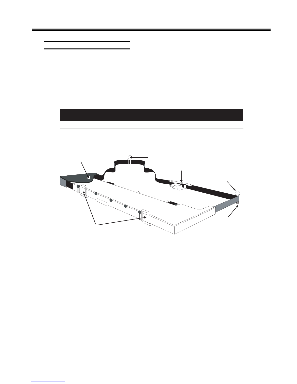
Figure 2-6. Nonshifting Ribbon Cartridge..................................................2-7
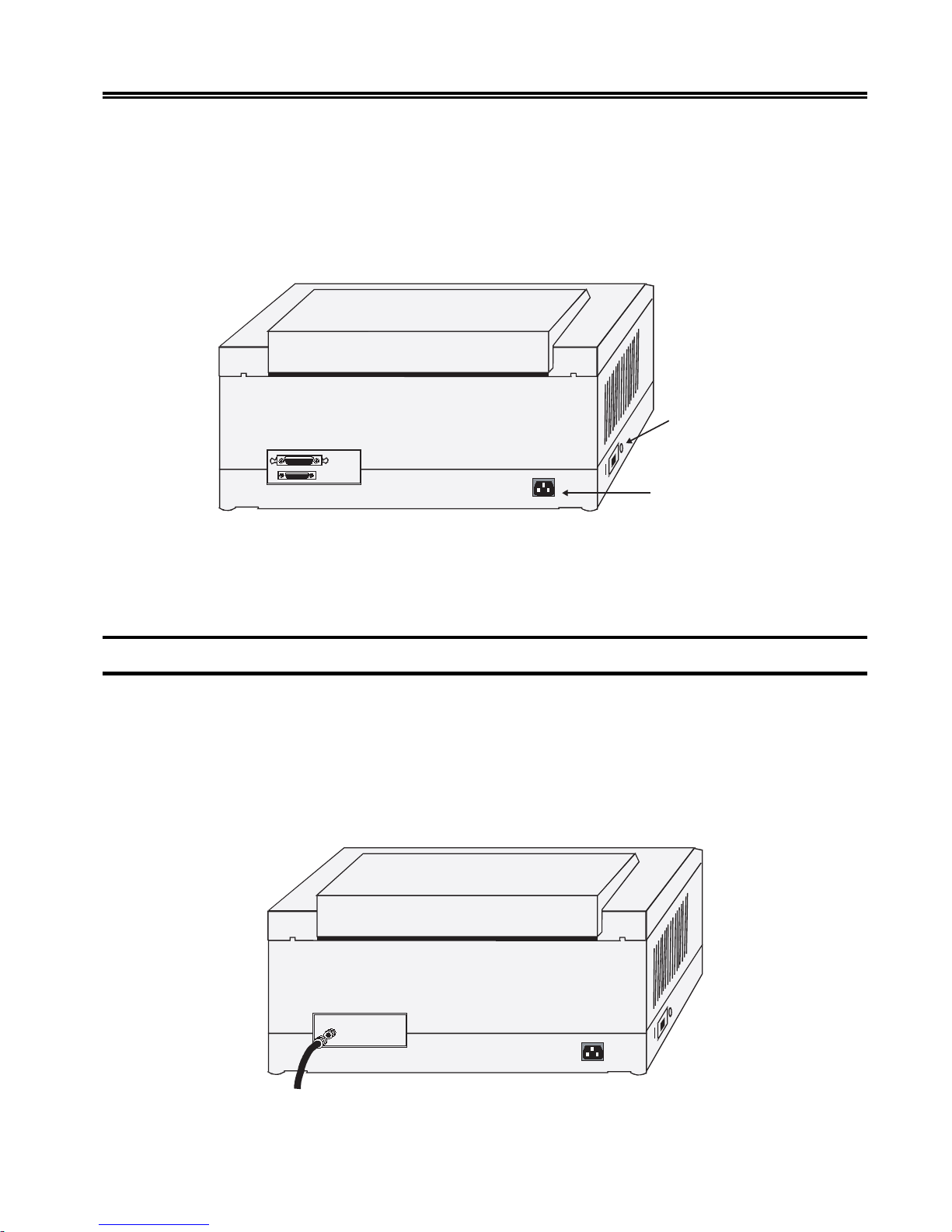
Figure 2-7. Installing the AC Power Cord ..................................................2-9
Figure 2-8. Connecting the Coax Cable .....................................................2-9
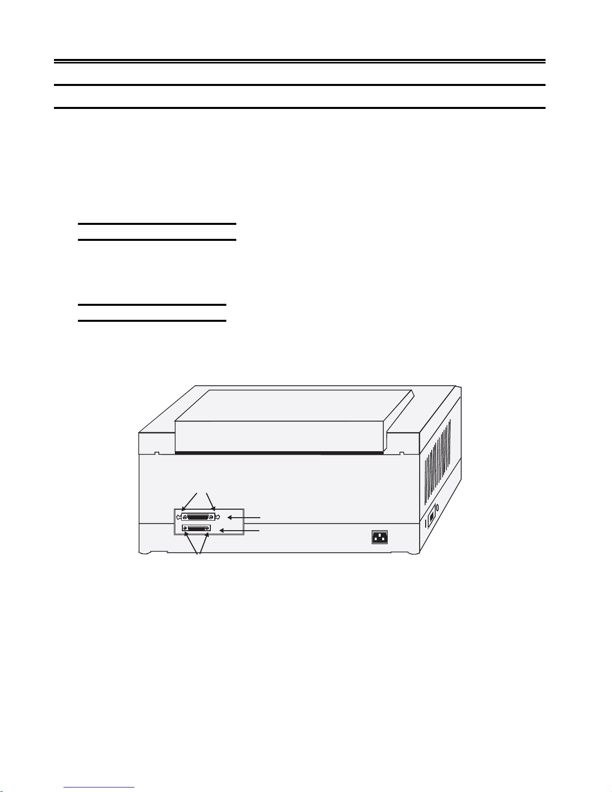
Figure 2-9. Connecting a Parallel or Serial Cable ....................................2-10
Figure 2-10. Forms Specifications - Physical Requirements......................2-12
Figure 2-11. Forms Specifications - Print Positioning................................2-13
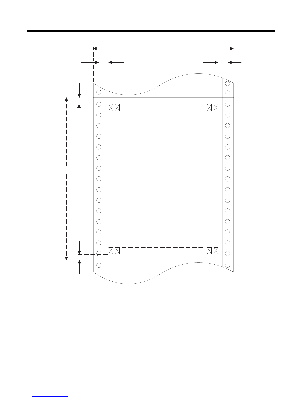
Figure 2-12. Print Positioning - Continuous Forms....................................2-14
Figure 2-13. Print Positioning - Single Part Forms.....................................2-15
Figure 2-14. Paper Feed Slots.....................................................................2-17
Figure 2-15. Open Tractor Door .................................................................2-18
Figure 2-16. Flipping the Tractor Lever .....................................................2-18
Figure 2-17. Inserting Paper - Continuous Forms Module .........................2-19
Figure 2-18. Platen Gap Lev er....................................................................2-20
Figure 2-19. Forms Handler Module (DOD Option)..................................2-21
Figure 2-20. DOD Option with Roller Drive..............................................2-23
Figure 2-21. Forms Handler Module (DID Option) ...................................2-23
Figure 2-22. Inserting Paper - Forms Handler Module...............................2-24
Figure 2-23. DID Option with Roller Drive ...............................................2-25
Figure 3-1. 1330 Operator Control Panel ...................................................3-1
Figure 3-2. Status Display ..........................................................................3-1
Figure 4-1. Aligned and Unaligned Dots in Characters............................4-19
Figure 5-1. Aligned and Unaligned Dots in Characters............................5-16
Figure 7-1. Replacing the Print Head .........................................................7-3
Figure 7-2. Carriage Restraining Hook ......................................................7-3
Figure 7-3. Mounting Screws .....................................................................7-4
Figure 7-4. Carriage - Side View ................................................................7-5
Figure 7-5. Proper Print Registration..........................................................7-5
Figure 7-6. Increase Print Registration Value .............................................7-7
Figure 7-7. Decrease Print Registration V alue............................................7-8
Figure B-1. Escape Sequence Structure ...................................................B-13
Figure B-2. Table for Selecting Escape Character ...................................B-15
Figure B-3. Escape Codes ........................................................................B-18
Figure B-4. Bar Code T ypes..................................................................... B-20
Figure B-5. Calculating New Line Characters ......................................... B-23
Figure B-6. OCR-A Character Set ........................................................... B-25
Figure B-7. OCR-B Character Set ........................................................... B-26
701333-004 ix
Page 9

Chapter 1. Introduction
The MTX 1330 Printer is designed for high-volume printing and combines high reliability
with convenient features such as modular paper handling, a 4-line, 80-character LCD
that displays menus, an automatic forms thickness adjustment, and self-diagnostic
messages. The 1330 produces clear, precise printing on up to six-part forms,
accommodates continuous forms and cut sheet paper, and operates quietly for office
environments.
A serial dot matrix bidirectional impact printer, the 1330 is av ailable in one model:
• 1330-X02
This model prints in four qualities. The maximum print speeds (at 10 CPI in monochrome)
in each quality are as follows (CPS = characters per second):
tfarDtsaF
*ytilauQ
SPC005SPC004SPC052SPC521
The 1330 is available with an 18-wire-shifting ruby print head. Output can be
monochrome, four colors or 8 colors, depending on the ribbon cartridge installed.
Comprehensive graphics support is offered through All Points Addressable (APA)
Programmed Symbols, as well as Intelligent Printer Data Stream (IPDS). The 1330 also
supports APL and 39 international character sets.
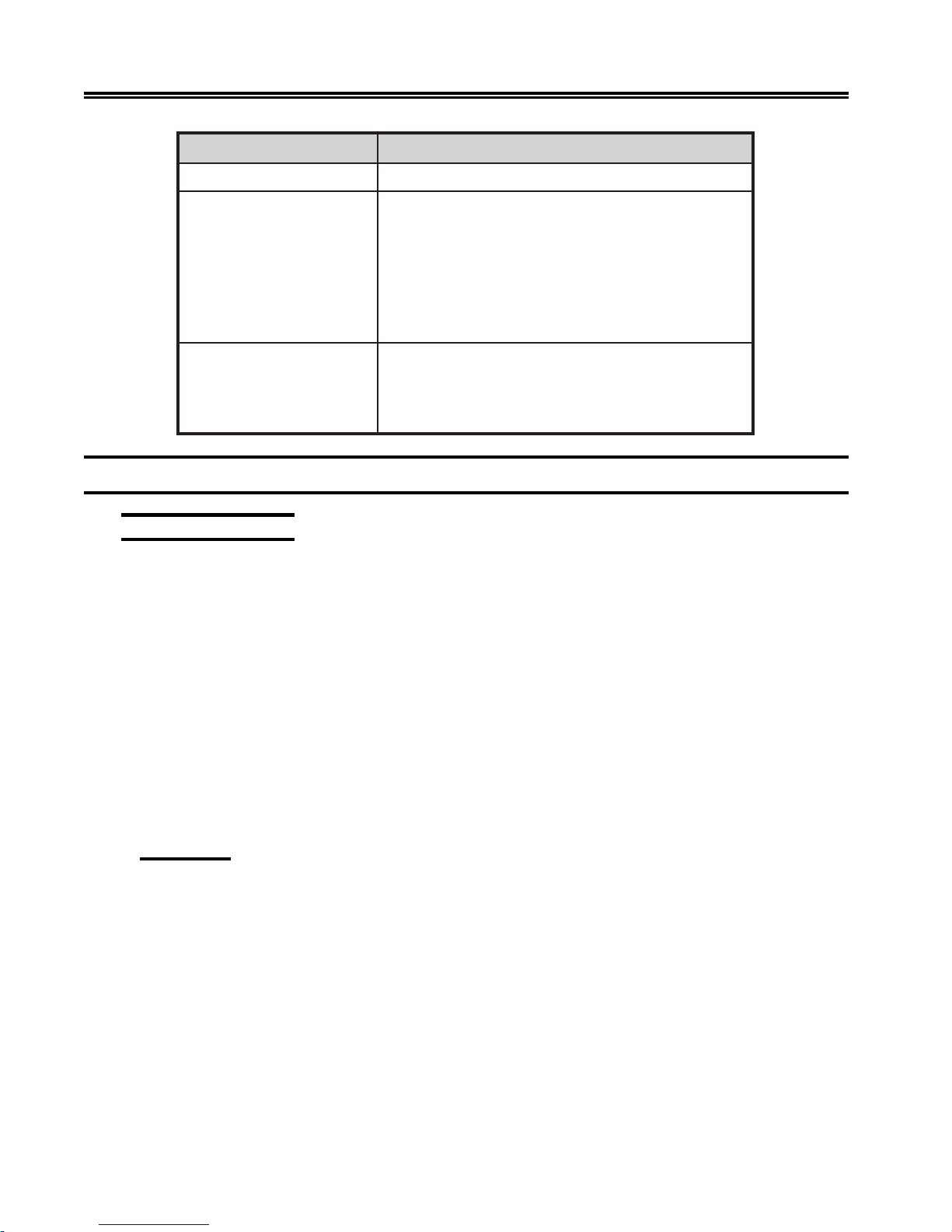
The 1330 supports several attachment cards that offer the highest possible flexibility for
your corporate printing strategy . Some of the attachment cards feature a 3270 interface
port, and parallel and serial ASCII input ports, thereby enabling automatic printer sharing
between 3270 hosts and personal workstations. (See table at the top of the following
page.)
*Fast Draft is only available in 3270 mode.
ytilauQ
gnissecorPataD
gnissecorPataD
ytilauQtxeT
retteLraeN
ytilauQ
701333-004 1-1
Page 10
Introduction
sdraoBtnemhcattA stnemnorivnEnoitacinummoC
xaoCsretpadaxaoC-Ahtiwsrellortnocdnastsoh0723-
)lauD(IICSA/xaoCsretpadaxaoC-Ahtiwsrellortnocdnastsoh0723-
IICSAMBI(sretupmocinim,snoitatskrow,semarfniaM-
Interfacing with the 1330
A-Coax Attachment
,).cte,004SAMBI(sretupmocinim,semarfniaM-
htiwsretupmoclanosrepdna,snoitatskrow
laires234SR/232SRdnalellarapscinortneC
secafretni
ehtneewtebgnirahsretnirpgnihctiwsotuastroppuS
.tsohIICSAdna0723
htiwsretupmoclanosrepdna,).cte,004SA
laires234SR/232SRdnalellarapscinortneC
secafretni
The 1330 Coax can be attached to the following controllers via an A-type coax cable:
• T elex 046, 076, 274, and 276 controllers
• Memorex 2076, 2174, and 2274 controllers
• Memorex Telex 1174, 1274, and 1374 controllers
• IBM 3174, 3274, and 3276 controllers with “ A” terminal ports
• IBM 3694 Document Processor
• IBM 4321, 4331, 4341, and 4361 processors through the standard display/printer
adapter or expansion feature
• IBM 9370 processor
Emulation
The following printer emulations are av ailable as standard features on the 1330 Coax:
• IBM 3268 – Emulates a non-IPDS IBM 4224 printer with IBM 3628 programmed
symbols
• IBM 4224 – Emulates an IBM 4224 printer
• IBM 4230 – Emulates an IBM 4230 printer
• 2124 – Emulates a non-IPDS IBM 4224 printer with IBM 3268 programmed symbols
and supports escape codes to select bar codes, formatting, fonts, highlighting, OCR
printing, and so on
1-2 701333-004
Page 11

ASCII Attachment
With an ASCII attachment, the follo wing features are av ailable on the 1330.
Interfaces
The following interfaces are software selectable from the front panel:
• Centronics parallel
• RS-232C
• RS-422
Emulation
The following printer emulations are available as standard features on the 1330 ASCII:
• IBM Proprinter III and III XL
• TI-810 modified
Introduction
Character Codes
In ASCII mode, the American Standard Code for Information Exchange (ASCII) character
set is recognized by the 1330. See Appendix C, “Character Sets,” for information about
ASCII character sets.
Print Buffer
In ASCII mode, the print b uffer is a reserv ed area of memory for storing incoming data
before it is printed. The buffer size is operator selecta ble for 2K, 8K, 16K, or 32K bytes.
ASCII Languages
The 1330 supports international languages through the use of its internal PC character
set. Selection is made from the front panel during printer configuration.
Standard Features
Standard features of the 1330 are described below . Information for using these printing
capabilities is presented in subsequent chapters of this manual.
Character Codes
In 3270 mode, the Extended Binary Coded Decimal Interchange Code (EBCDIC)
character set is recognized by the 1330, as well as the SNA Character String (SCS). See
Appendix B of this manual for character code charts for SCS support.
701333-004 1-3
Page 12

Introduction
Color
The 1330 can print in monochrome or color, using an operator installable recirculating
cloth ribbon cartridge. Two monochrome ribbons, a 4-color accent ribbon (black, red,
blue, and green), and a subtractive 8-color r ibbon (black, red, blue, green, yello w, magenta,
cyan, and brown) are a vailable.
Paper Handling
The 1330 comes standard with pull tractors for continuous forms feeding, and allows for
easy paper loading at the front of the printer . Pinfeed forms from 3 to 14 inches (7.6 to
35.6 cm) long and 3 to 15 inches (7.6 to 38.1 cm) wide can be used. This configuration is
especially suited for a large volume of work or work that requires little operator
intervention.
Print Qualities
The 1330 can print in four qualities:
• Fast Draft Quality (FD) (av ailable only in 3270 mode)
• Data Processing (DP)
• Data Processing T e xt (DP Text)
• Near Letter Quality (NLQ)
All print qualities are selectable via the operator control panel.
Multiple Copies
The 1330 can print multiple copies, one original plus five copies, total thickness not to
exceed 0.025 inch (0.64 mm). The recommended maximum thickness for multipart forms
is 0.018 inch (0.46 mm).
3270 Languages
The 1330 enables the operator to select from 39 international language character sets.
Selection is made during printer configuration. The attached control unit should be
configured for the same language.
Screen Sizes
Any of the following display buf fer sizes can be selected for print operation:
• 1920 bytes
• 2560 bytes
1-4 701333-004
Page 13

• 3440 bytes
• 3564 bytes
The size can be selected by the operator during configuration.
Self-Diagnostic T esting
The 1330 has a self-diagnostic ability to ensure that the printer is in good working
condition. If an error condition is encountered, the 1330 informs the operator by displaying
an error message on the control panel. Should this occur, refer to the er ror message chart
in Appendix A of this manual.
Audible Alarm
The 1330 features an audible alarm that sounds when the printer needs operator assistance
(such as when the paper is skewed or out). In this situation it will continue to beep
intermittently , unless it is disabled.
Programmed Symbols
Introduction
In 3270 mode, six symbol sets are operator configurable either as six single plane sets or
as three single plane sets and one triple plane set.
IPDS
Intelligent Printer Data Stream (IPDS) is a structured field datastream for managing
printing processes and data objects. IPDS uses All Points Ad dressability (AP A) to enable
the user to position text, graphics, image data, overlays, and bar codes at any defined
point on a printed page. Extended memory is recommended for graphics applications.
Optional Features
The following optional accessories are available for the 1330. These items can be ordered
through your sales representative.
Memory
This feature adds 512K bytes of RAM memory to the standard 128K bytes of memory
for a total of 640K bytes. The extra memory is recommended for the following
applications: IPDS, programmed symbols, ASCII graphics, ASCII do wnloaded fonts,
and dual host (auto-switching) operations.
Continuous Forms Module
The continuous forms module provides the operator with a reliable way of feeding the
1330 with continuous forms.
701333-004 1-5
Page 14

Introduction
Forms Handler Module
The Forms Handler module is operator installable in the front of the printer to vertically
position forms. The module’ s forms tractors are adjustable for two options:
• Document on Demand (DOD) option – used for continuous forms
• Document Insertion Device (DID) option – used for cut sheet/single sheet forms
Printer Pedestal Stand
The pedestal stand is designed so that the printer can be securely seated. The forms
supply is placed in the stand’s paper compartment and feeds into the front of the 1330
from below .
Forms Stand
The forms stand is placed behind the printer to hold both new and printed fanfold forms.
Related Manuals
Appendix D of this manual contains programming information for special 1330 escape
codes.
For more information on printer control codes in Appendix B, see the IBM 4224 Printer
Product and Programming Description Manual, GC31-2551; IBM 4230 Printer Product
and Programming Description Manual, GC40-1701-00; IBM 3270 Information and
Display System, GA23-0061; IBM 3268 Printer Models 2 and 2C Description, GA273268; IBM Pr oprinter III and IIIXL Guide to Operations, SA34-2065-1; IBM Pr oprinter
F amily T echnical Reference, SC31-2589-3; and the ANSI Standar d X3.64-1979.
1-6 701333-004
Page 15

Chapter 2. Preparing to Operate
The 1330 printer has been designed for customer setup and preliminary check. Please
read this chapter before you try to install or relocate your 1330.
Inspecting the Package
When the packaged 1330 printer arrives, inspect the carton for physical damage before
unpacking it. If the carton is damaged, do not open it. Notify the T raff ic De partment or
your sales representative, as appropriate.
Also call the delivery carrier to request examination of the damage. The carrier is required
to complete and sign a damage report form.
If you do not see any damage, unpack the printer according to the follo wing instructions.
Unpacking the Printer
the 1330
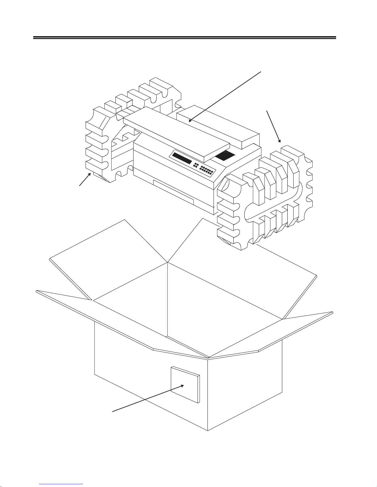
Refer to Figure 2-1 and follow these steps to unpack the 1330:
Caution
The 1330 weighs 66 pounds (29.9 kg). T w o people may be required to mov e the printer
to its operating location.
1. Move the packaged printer to the work area and place the car ton in an upright position.
2. Remove the packing list envelope from the outside of the box.
3. Open the flaps to the top of the box.
4. Remove the operator’s manual from the top of the printer .
5. Remove the continuous forms module feature (if ordered) located on top of the
printer.
6. Remove the printer from the box and remove the foam end caps and the bag from
the printer.
7. Remove the protective film from the top of the printer .
8. Lift the printer cover and remove the ribbon and power cord.
701333-004 2-1
Page 16
Preparing to Operate the 1330
Left End Cap
Continuous Forms
Module Feature
Right End Cap
Packing List Envelope
2-2 701333-004
Figure 2-1. Unpacking the 1330
Page 17
Preparing to Operate the 1330
Shipping T ube
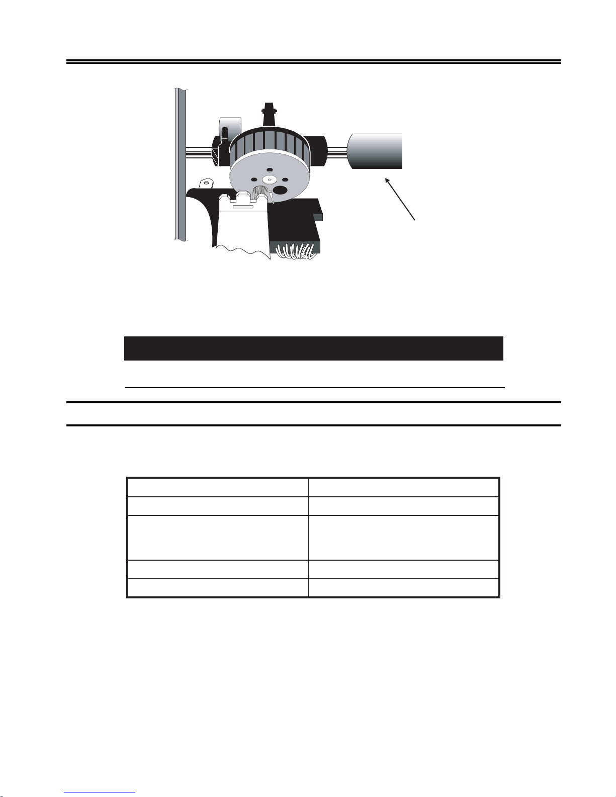
Figure 2-2. Foam Shipping Tube
9. The carriage on the 1330 is restrained by a foam shipping tube to prevent shifting during
shipping. Before installing the printer, remove this tube, illustrated in Figure 2-2.
Failure to remove the carriage shipping tube before turning on the 1330 may result in
damage to the printer.
Installation Preparation
The location for the 1330 must meet the following physical and environmental
requirements:
:rewoPesahpelgnis,zH36-74taCAV462-09
:ecnaraelCsedisllano)mc2.51(ni6
:snoisnemiDediw)mc5.56(ni8.52
:ytidimuHevitaleR)gnisnednocnon(%08ot%8
After unpacking the 1330, you are now ready to begin installing it.
Caution
hgih)mc5.13(ni4.21
peed)mc8.74(ni8.81
:egnaRerutarepmeTgnidnuorruS)C6.04-01(F501-05
701333-004 2-3
Page 18
Preparing to Operate the 1330
Installing the Ribbon Cartridge
A monochrome ribbon cartridge is shipped with the 1330. Remember that if you have a
monochrome ribbon installed, the 1330 will print in one color only. A multitrack color
ribbon cartridge must be installed to allow printing in different colors.
Ordering Ribbons
Y ou can use a Shifting ribbon or a Nonshifting ribbon in the 1330-X02. The ribbons have
the same character life and for monochrome printing can be used interchangeably.
Caution
Use only approved ribbons that are av ailable from MTX. Third party ribbons may not be
compatible, resulting in improper operation and decreased print head life.
To order additional ribbon cartridges for the 1330-X02, contact your MTX Sales
Representative. Request the following ribbon cartridge part number(s):
epyTnobbiR N/PXTM
Following are instructions for installing each ribbon type.
Installing a Shifting Ribbon
This section explains how to install a Shifting ribbon cartridge. Y ou will need to install a
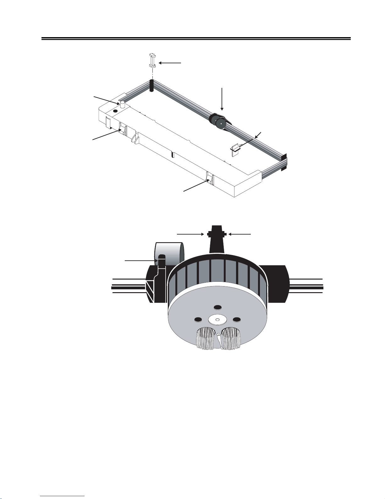
new ribbon when the existing ribbon wears out. Refer to Figure 2-3.
1. Make sure that the printer’s Power switch is in the O (OFF) position. Unplug the
power cord from the outlet.
2. Raise the printer cover.
3. Set the platen gap lever away from the platen (toward you) as far as it will go (see
Figure 2-4).
4. Slide the print head to the middle of the printer.
The print head may be hot. To move it, grasp the pr int head driv e belt.
gnitfihS–)tneccA(roloC-4200-078559
gnitfihsnoN–emorhconoM100-263559
Caution
2-4 701333-004
Page 19
Preparing to Operate the 1330
Removable Corner Guides
Ribbon Drive
Gear Knob
Mounting Clip
Platen Gap Lever
Mounting Clip
Figure 2-3. Shifting Ribbon Cartridge
Ribbon Shifter Button
Ribbon Shifter Guide
Ribbon Stop (REMOVE
AFTER INSTALLATION)
Ribbon Shifter Button
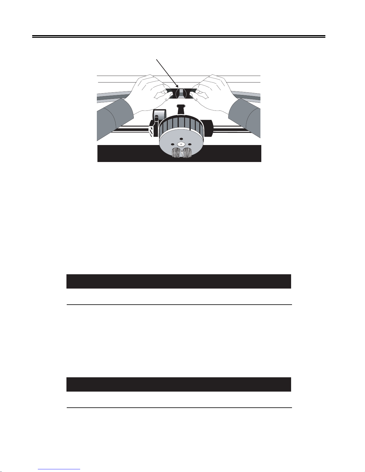
5. If you are replacing the ribbon cartridge, grasp both sides of the ribbon shifter guide,
as illustrated in Figure 2-5, and gently bend the sides toward the rear of the printer .
The ribbon shifter guide will disengage. Lift it away from the printer .
701333-004 2-5
Figure 2-4. Platen Gap Lever
Page 20
Preparing to Operate the 1330
Ribbon Shifter Guide
Figure 2-5. Disengaging the Ribbon Shifter Guide
6. If you are replacing the ribbon car tridge, lift out the old cartridge and remove the
plastic corner guides. Reinstall the new corner guides (they are packed in the ne w
ribbon cartridge package) over the corner guide brackets.
7. Snap the new ribbon cartridge into place. Make sure that the tabs on the front and
back of the cartridge snap into the slots on the ribbon cartridge bracket.
8. Pull the ribbon stop out of the cartridge and put the stop aside for later use.
9. Install the r ibbon shifter guide by positioning it above the nose of the print head,
then press the guide down until it rocks into place on the ribbon shifter buttons. If
the ribbon shifter guide is properly installed, it will rotate smoothly.
Caution
Make sure that the barrel fits snugly against the print head nosepiece. Otherwise, it will
not shift properly.
10. Use the tapered end of the ribbon stop to route the ribbon around the right and left
corner guides.
11. Turn the ribbon drive gear knob counterclockwise several times to make sure the
ribbon is feeding properly .
12. Slide the print head to the far left and reset the platen gap lever to the appropriate
position to accommodate the thickness of the forms. If necessary, refer to “Setting
the Platen Gap Lever” later in this chapter. Close the printer cover.
Caution
If the platen gap adjustment is set too close to the paper, the life of the print head will be
reduced and the print head may be damaged.
13. Connect the printer to a power source, as explained later in this chapter .
2-6 701333-004
Page 21
Installing a Nonshifting Ribbon
Follow these steps to install or replace a Nonshifting ribbon cartridge. Refer to Figure 2-6.
Note that the Nonshifting ribbon is monochrome only.
1. Turn the printer off and unplug the power cord from the outlet.
2. Raise the printer cover.
3. Set the platen gap lever away from the platen (toward you) as far as it will go (see
Figure 2-4).
The print head may be hot. To move it, grasp the print head driv e belt.
4. Slide the print head to the middle of the printer.
5. Grasp the ribbon guide, as illustrated in Figure 2-6, and lift it from the print head.
Preparing to Operate the 1330
W arning
Ribbon Advance Knob
Cassette T abs
Figure 2-6. Nonshifting Ribbon Cartridge
6. Remove the used corner guides. The new corner guides are attached to the new
ribbon. (On Shifting ribbons, the corner guides are separate.)
7. Release the left end of the cartridge first. Push back the metal spring clip on the
printer, and squeeze the cassette tabs. Lift the left end of the cartridge clear, then
push the metal spring clip forward to release the right end.
8. Pull the ribbon guide from the body of the ne w cartridge and make sure the ribbon is
not twisted.
Corner Guide
Ribbon Guide
Corner Guide
Ribbon
Turning Post
9. Seat the car tridge onto the platform. Press down along the top of the cartridge to
ensure that it is firmly seated, with the cassette tabs snapped into the openings in the
platform.
10. Slide the plastic corner guides onto the ribbon turning posts while making sure the
ribbon is not twisted. Make sure that the corner guides are pressed all the way down.
701333-004 2-7
Page 22

Preparing to Operate the 1330
11. Snap the ribbon guide onto the print head. The ribbon guide must fit securely on the
ribbon shifter buttons shown in Figure 2-4. Make sure the ribbon is not twisted.
12. T ak e up the ribbon slack by turning the ribbon advance knob in the direction of the
arrow .
Caution
If the platen gap adjustment is set too close to the paper, the life of the print head will be
reduced and the print head may be damaged.
13. Close the printer cover .
14. Connect the printer to a power source, as explained in the next section.
Connecting the Printer to a Power Source
A v oid connecting the 1330 to a po wer source shared by devices such as motors or fans
that may cause low fluctuating voltage or that may introduce noise into the power supply .
Unstable voltage can cause the printer to operate erratically .
Uncoil the A C po wer cord. Plug the socket end of the power cord into the r eceptacle on
the back of the 1330 (see Figure 2-7), then plug the connector end of the power cord into
the proper A C outlet.
Power Cable Requirements
For operation at 100-120V: The power cable required for domestic units is a UL listed,
CSA certified, 18/3 AWG, type SVT or SJT cable (15-foot [4.6-meter] maximum). It is
terminated on one end by a 125V, 15A grounding type attachment connector. It is
terminated at the other end by a 125V, 15A parallel blade, grounding type attachment
plug.
For operation at 200-240V: The power cable required for domestic units is a UL listed,
CSA certified, 18/3 AWG, type SVT or SJT cable (15-foot [4.6-meter] maximum). It is
terminated on one end by a 250V, 15A grounding type attachment plug body. It is
terminated at the other end by a 250V, 15A tandem blade, grounding type attachment
connector.
The power cable required for international units is an 18/3 AWG, type SJT cable (15foot [4.6-meter] maximum). It is terminated on one end by a 250V, 15A grounding type
attachment plug body. It is terminated at the other end by a 250V, 15A grounding type
cord connector. The cord set is marked HAR to signify appropriate safety approvals.
The installation site must provide a properly wired and grounded power outlet. Circuits
connected to air conditioners and devices that generate significant transient electrical
noise should be avoided.
Electrostatic discharge in the vicinity of the unit should be minimized by avoiding high
resistance floor material and carpeting that does not have antistatic properties, avoiding
the use of plastic seats and covers, and avoiding lo w humidity levels. The unit should be
located away from areas that generate electromagnetic interference (for example,
2-8 701333-004
Page 23
Preparing to Operate the 1330
transformers, power distribution panels, and motors). The unit should not be installed
where the atmosphere contains corrosive elements that may damage the unit.
Cable runs should avoid areas that produce electromagnetic interference (for example,
near transformers, switching equipment, power distribution panels, and under carpets
where vacuum cleaning is done). Also, heavy equipment should not be mo ved or rolled
over the cable.
Power-On/Off
Switch
AC Power Cord
Receptacle
Figure 2-7. Installing the AC Power Cord
After installing the ribbon cartridge and connecting the 1330 to a power source, you are
ready to connect the coax cable.
Connecting the Coax Cable
Before you connect the coax data cable, make sure the Power switch is in the O (OFF)
position.
Route the coax cable to the coax connector receptacle on the back of the 1330. See
Figure 2-8. Plug the cable connector into the receptacle and turn the connector clockwise
until the slots on the side of the connector lock against the studs on the side of the
receptacle.
701333-004 2-9
Figure 2-8. Connecting the Coax Cable
Page 24
Preparing to Operate the 1330
Connecting a Parallel or Serial Cable
T o comply with FCC regulations, use one of the follo wing cables:
• Parallel cable – MTX P/N 956588-001 (36-pin, 6 ft. EIA).
• RS-232 serial cable – This is available as P/N 957520-0 10 (10 feet). For other RS-232
or RS-422 applications, use locally available cables.
Before you connect the cable, make sure the Power switch is in the O (OFF) position.
Connecting a Parallel Cable
Push the male end of the parallel cable into the parallel receptacle on the back of the
1330 (see Figure 2-9). Push the wire guards, located at each end of the receptacle, in,
over the cable end, to hold the cable in place.
Connecting a Serial Cable
Loosen the screws at each end of the serial receptacle on the back of the 1330 (see Figure
2-9). Push the male end of the serial cable into the serial receptacle. Tighten the scre ws
to hold the cable in place.
Wire Guards
Parallel Receptacle
Serial Receptacle
Screws
Figure 2-9. Connecting a Parallel or Serial Cable
2-10 701333-004
Page 25

Powering on the 1330
Turn the printer on by setting the Power switch to the | (ON) position (see Figure 2-7).
When the printer is powered on, B ASIC ASSURANCE TEST IN PR OGRESS will appear
in the display window . The Basic Assurance T est (B AT) tests various components of the
1330 and ensures that the printer is ready for operation. The current status of the test in
progress is displayed in the bottom row. If an error condition is encountered during the
BAT, the B A T will halt and the error message will be displayed. For a list of er ror messages
and recovery procedures, refer to Appendix A of this manual.
Note: If you have been following the pr ocedures for printer installation as presented
in this chapter, the display will indicate that there is no paper in the printer.
Continue to follow these procedures.
When the BAT is completed successfully (within a few seconds), the READY message
will appear in the display window . In 3270 mode, if communications hav e been established
with the host system, Cu will display . If communications have not been established with
the host, the display will read READY, and Cu will disappear in about 30 seconds.
Preparing to Operate the 1330
The next step is to check your forms against the 1330 forms specifications.
Forms Specifications
Before installing the forms, you should review the forms you intend to use to make sure
they meet 1330 specifications. Figures 2-10 through 2-13 show these specifications.
Specifications are given for the two types of form feed mechanism available for the
1330, the Continuous Forms module and the Forms Handler module (with both the
Document on Demand [DOD] option and Document Insertion Device [DID] option).
701333-004 2-11
Page 26

Preparing to Operate the 1330
epyTeludoMABB
smroFfoepyTsuounitnoCsuounitnoCelgniS
htgneL
mumixaMni0.41ni0.41ni0.41
muminiMni0.3ni0.3ni5.7
htdiW
mumixaMni0.51ni0.51ni0.51
muminiMni0.3ni0.3ni0.3
ssenkcihTsmroF
traPelgniS
mumixaMni600.0ni600.0ni600.0
muminiMni300.0ni300.0ni300.0
suounitnoCDODDID
eludoMsmroFnoitpOnoitpO
mc6.53mc6.53mc6.53
mc6.7mc6.7mc0.91
mc1.83mc1.83mc1.83
mc6.7mc6.7mc6.7
mm51.0mm51.0mm51.0
mm80.0mm80.0mm80.0
trapitluM
elbawollAmumixaMni520.0ni520.0ni520.0
mm46.0mm46.0mm46.0
dednemmoceRmumixaMni810.0ni810.0ni810.0
mm64.0mm64.0mm64.0
trapitluMniteehShcaE
mumixaMni600.0ni600.0ni600.0
mm51.0mm51.0mm51.0
muminiMni200.0ni200.0ni200.0
mm50.0mm50.0mm50.0
straPelpitluM
*elbawollAmumixaM666
dednemmoceRmumixaM441
*thgieW
traPelgniS
**mumixaMbl04bl04bl04
muminiMbl51bl51bl51
trapitluMniteehShcaE
**mumixaMbl04bl04bl04
muminiMbl21bl21bl21
*Specifications are applicable in coordination with forms thickness specifications.
**Forms should be tested by the customer for acceptability.
Figure 2-10. Forms Specifications - Ph ysical Requirements
2-12 701333-004
Page 27

Preparing to Operate the 1330
suounitnoCDODDID
eludoMsmroFnoitpOnoitpO
)A(htdiWsmroF
mumixaMni0.51ni0.51ni0.51
mc1.83mc1.83mc1.83
muminiMni0.3ni0.3ni0.3
mc6.7mc6.7mc6.7
)B(htgneLsmroF
mumixaMni0.41ni0.41ni0.41
mc6.53mc6.53mc6.53
muminiMni0.3ni0.3ni5.7
mc6.7mc6.7mc0.91
)C(noitisoPtnirPtsriF
mumixaMni56.0ni56.0ni56.0
mc7.1mc7.1mc7.1
muminiMni51.0ni51.0ni51.0
mc83.0mc83.0mc83.0
)D(noitisoPtnirPtsaL
muminiMni52.0ni52.0ni52.0
mc46.0mc46.0mc46.0
)E(eniLtnirPtsriFni052.0ni526.0ni005.0
mc46.0mc95.1mc72.1
)F(eniLtnirPtsaLni52.0ni52.0ni52.0
mc46.0mc46.0mc46.0
Figure 2-11. Forms Specifications - Print P ositioning
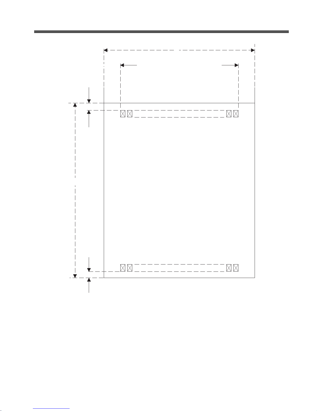
Refer to Figures 2-12 and 2-14 for an explanation of the meaning of the letters A through F.
701333-004 2-13
Page 28
Preparing to Operate the 1330
A
C
E
B
D
F
Figure 2-12. Print Positioning - Continuous Forms
2-14 701333-004
Page 29
Preparing to Operate the 1330
A
C
E
B
D
F
Figure 2-13. Print Positioning - Single Part F orms
701333-004 2-15
Page 30

Preparing to Operate the 1330
Review the following points carefully to ensure that your forms are appropriate for use
in the 1330.
1. Except for horizontal dimensions of the first print position specif ied in Figures 2-12
and 2-13, no printing should occur within 0.25 inch (0.6 cm) of any edge, perforation,
or fold.
2. Printing m ust not occur across any holes, perforations, or edges of the forms, nor
should printing occur directly on the platen.
3. Continuous card stock forms are not recommended.
4. Nar row width forms (less than 8.0 inches [20.3 cm]) contribute to instability of
stacking and may require operator attention. W ider base forms are recommended.
5. The minimum single part forms thickness is 0.003 inch (0.08 mm). The maximum
single part forms thickness is 0.006 inch (0.15 mm).
6. The maximum allowable multiple part forms thickness is 0.025 inch (0.64 mm).
The maximum recommended multipart forms thickness is 0.018 inch (0.46 mm).
The minimum thickness for any sheet in multipart forms is 0.002 inch (0.05 mm)
(carbon excluded). The maximum thickness for any sheet in multipart forms is 0.006
inch (0.15 mm).
7. Up to six-part continuous part forms (original plus fi ve copies) can be used. Howeve r,
for optimum feeding, registration, and print quality, a maximum of four parts is
recommended. All multipart forms should be tested by the customer prior to use for
satisfactory feeding, registration, and print quality .
8. Carbon forms are recommended for multipart continuous forms. Carbonless (ink
impregnated) forms can be used but may result in less legible print than carbon
paper.
9. No hard or metallic fasteners are permitted.
10. Gluing is the recommended method of fastening forms. The gluing must be adequate
to prevent separation or shifting of the forms as they are fed through the printer .
11. Crimping is not recommended. However, if crimping is used, the crimps must be
located no more than 2 inches (5.1 cm) apart along the margins of the forms length.
12. Partial forms separation is not permitted.
13. Translucent or thin forms may cause the paper motion detector to give f alse readings.
The paper motion detector can be disabled, if required, to allow the use of these
forms (see Chapter 4).
Next is the procedure for using the Continuous Forms module.
2-16 701333-004
Page 31

Preparing to Operate the 1330
Installing the Forms – Continuous Forms Module
Forms are fed into the 1330 through the slot in the front of the printer, and exit out the
rear slot in the top, as illustrated in Figure 2-14.
Open for Top
Paper Exit
Module Flap
Front Slot
Optional Stand
Figure 2-14. Paper Feed Slots
T o install the f orms, follow these steps:
1. If the printer is powered on, press the Stop key to place the 1330 in Stop mode.
2. Raise the printer cover.
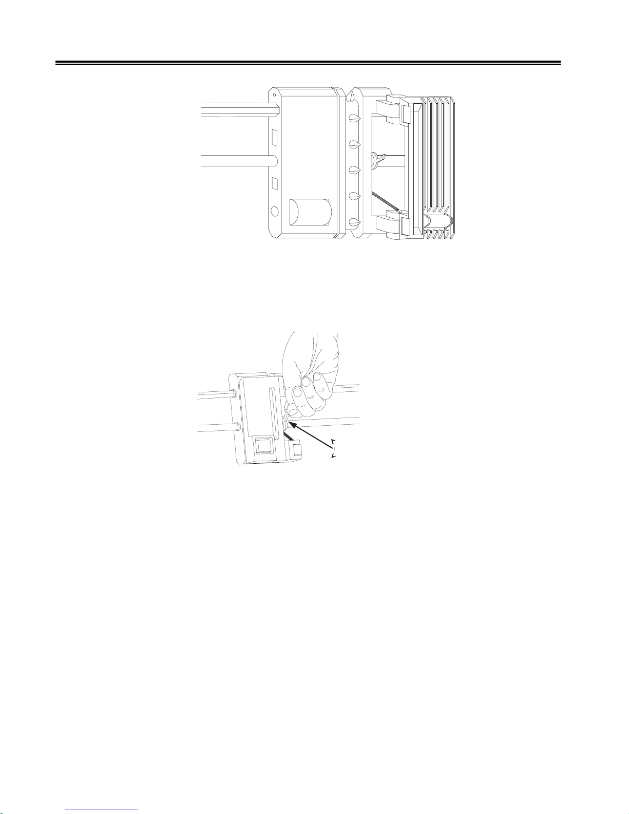
3. Open the tractor doors. Refer to Figure 2-15. If you are reloading pa per, remov e any
paper remaining in the printer .
To remove paper, pull the pinfeed holes on the sides of the paper away from the
tractor pins, tear off the paper above the tractors, and gently tug the paper a few
inches from where it enters the printer.
701333-004 2-17
Page 32
Preparing to Operate the 1330
Figure 2-15. Open T ractor Door
4. If the right forms tractor has not been adjusted for the paper width, loosen the tractor
by flipping the lever up, as illustrated in Figure 2-16. (Note that the left tractor
cannot be adjusted.)
Figure 2-16. Flipping the Tractor Le ver
5. Insert the paper through the front slot (see Figure 2-17). Continue hand feeding the
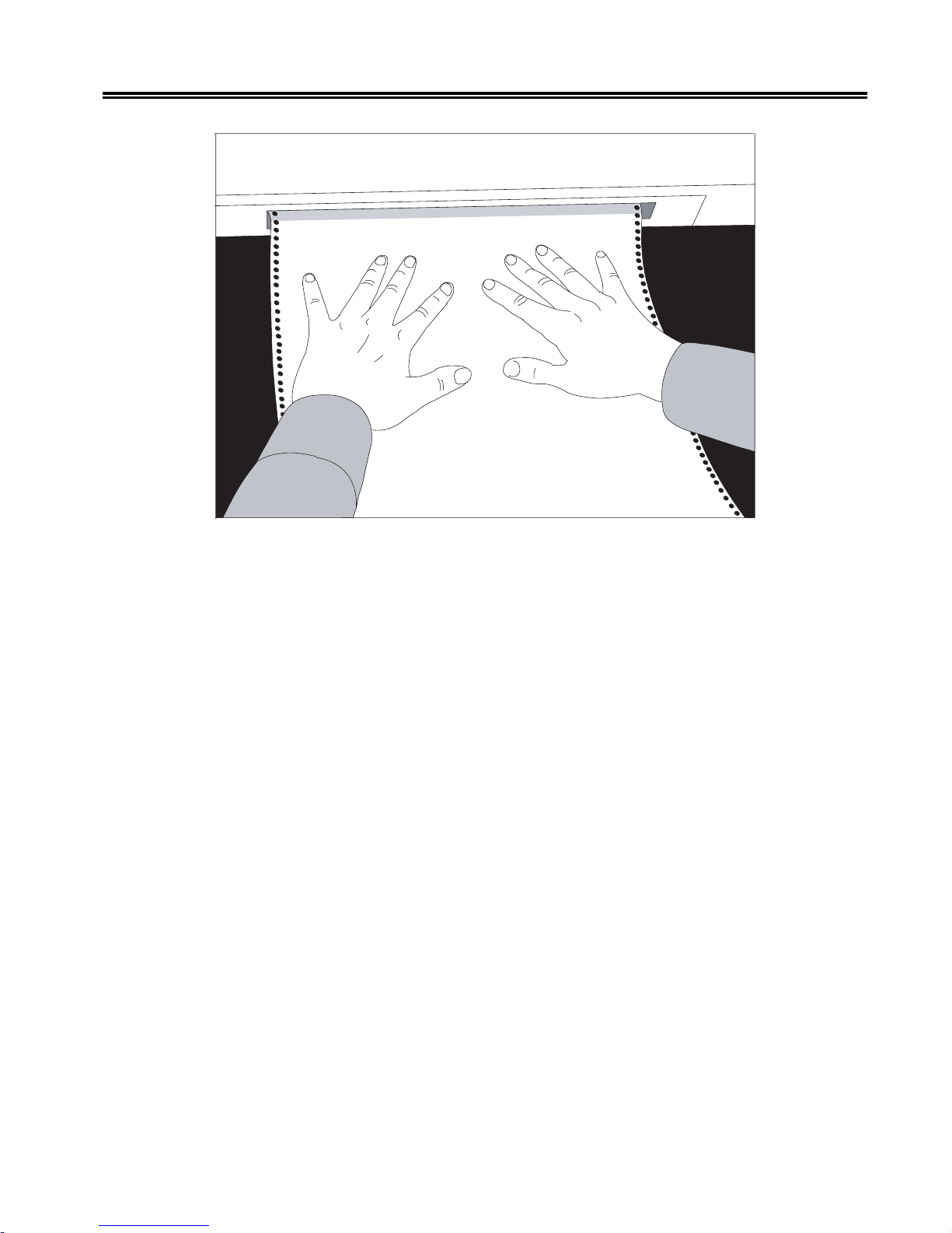
paper until the top of the paper appears flush with the top of the tractors.
6. Mo ve the platen gap le ver (Figure 2-18) tow ard you until it is completely open.
2-18 701333-004
Page 33
Preparing to Operate the 1330
Figure 2-17. Inserting Paper - Continuous Forms Module
7. Raise the module flap and position the paper so the pinfeed holes along the edge of
the paper fit evenly o ver the tractor pins. Slide the tractor, if necessary, to adjust for
the paper width.
8. When there is no slack in the paper, and it is aligned evenly , close the tractor doors.
9. Flip the tractor lever down to lock it in place, referring to Figure 2-16.
10. Before you close the printer cover, set the platen gap le v er as explained in the next
section.
11. Close the printer cover and lower the module flap.
Note: Whenever you close the printer cover, be sure to take hold of any forms that
have exited through the top slot, to prevent the forms from jamming up inside
the printer.
12. Press the Start key to enable printing.
701333-004 2-19
Page 34

Preparing to Operate the 1330
Setting the Platen Gap Lever
The platen gap lever , located on the carriage to the left of the print head (see Figure 2-18),
should be set according to the thickness of the forms being used.
Platen Gap Lever
Figure 2-18. Platen Gap Lever
To maximize print head life and performance, follow these instructions for setting the
platen gap lever when you reload forms:
For Single Part Forms
1. Set the platen gap lever away from the platen (toward you) as far as possible while
maintaining good print quality .
2. When printing becomes light with a fresh ribbon, or characters are formed
incompletely , move the le v er toward the platen one increment (one click).
3. If the print quality is not acceptable after you adjust the platen gap lever, refer to
“Checking Character W idth and Print Re gistration” in Chapter 7 of this manual.
Caution
If the platen gap lever is set too close to the paper, the life of the print head will be
reduced and the print head may be damaged.
For Multipart Forms
1. Set the platen gap lever away from the platen (toward you) as far as possible while
maintaining good print quality . Make sure the quality is good on the last part.
2. When printing becomes light with a fresh ribbon, or characters are formed
incompletely , move the le v er toward the platen one increment (one click).
2-20 701333-004
Page 35
Preparing to Operate the 1330
3. If the print quality is not acceptable after you adjust the platen gap lever, refer to
“Checking Character W idth and Print Registration” in Chapter 7.
Caution
If the platen gap lever is set too close to the paper, the life of the print head will be
reduced and the print head may be damaged. The platen gap lever must be far enough
from the platen to allow the shifter nosepiece to rotate smoothly , and to ensure that the
forms are not smudged by the ribbon.
Installing the Forms Handler Module
This section explains how to install the Forms Handler module using the Document on
Demand (DOD) option and the Document Insertion Device (DID) option.
Installing Forms Using the DOD Option
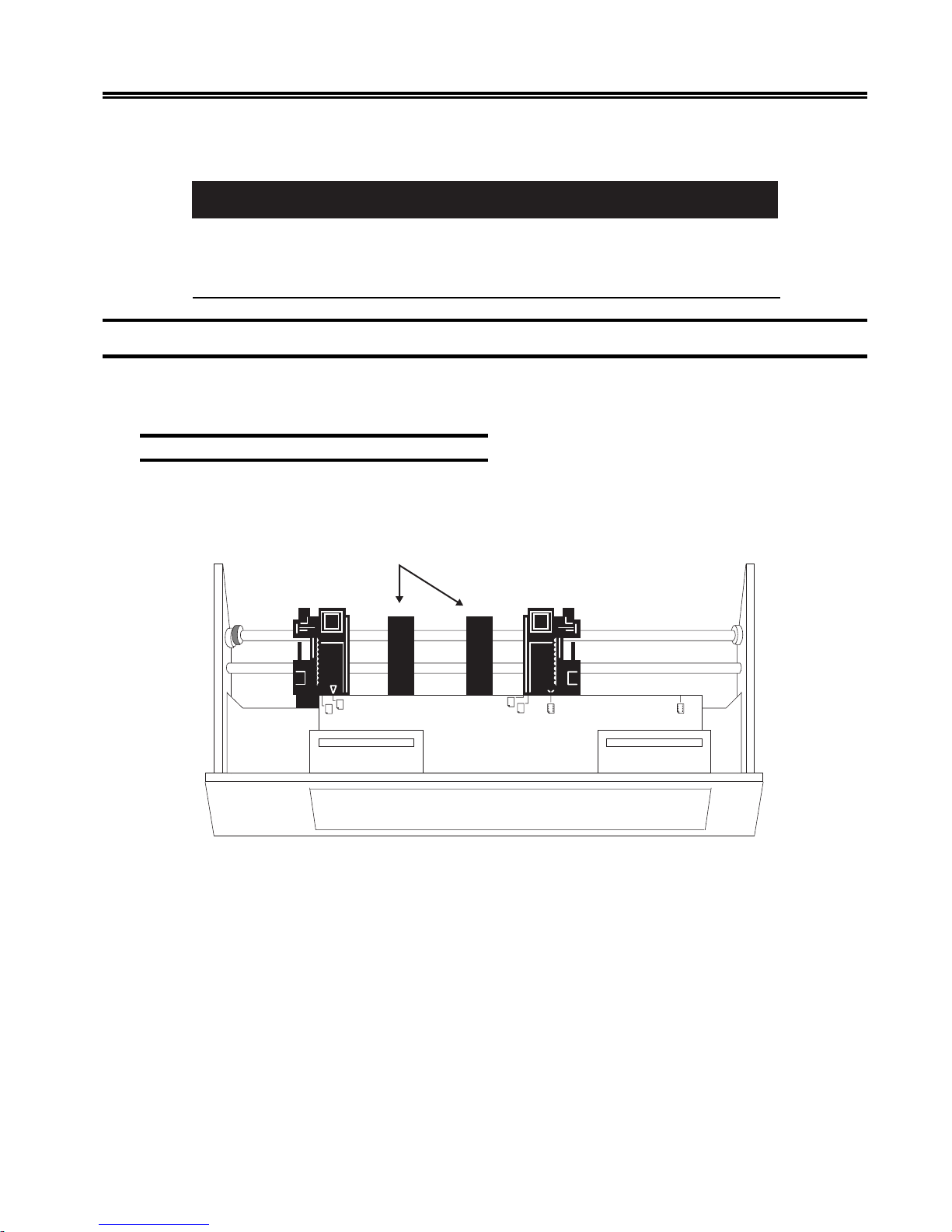
Refer to Figure 2-19 for a picture of the Forms Handler module set for the DOD option. In
this procedure, you will first load paper into the module, then put the module into the 1330.
Paper Supports
Figure 2-19. Forms Handler Module (DOD Option)
1. Make sure the printer power is on, and the printer is in Stop mode. If necessary,
press the Stop key .
2. For ease of handling, lay the module on the top of the printer.
3. Unlock the left forms tractor of the module.
4. Slide the left forms tractor to the right, as far as it will go.
5. Lock the left tractor.
6. Unlock the right forms tractor on the module.
701333-004 2-21
Page 36

Preparing to Operate the 1330
7. Move the right tractor to the approximate width of the forms you plan to use. Note that
three standard widths for computer pinfeed paper – 8 1/4 inches (21.0 cm), 9 1/2
inches (24.1 cm), and 14 7/8 inches (37.8 cm) – are marked on the module.
8. Center the paper supports (Figure 2-19) an equal distance from the tractors and
from each other . For narro w forms, you can snap out the paper supports.
9. Open the doors of both forms tractors.
10. Insert the paper into the front of the module, placing the paper on the tractor pins.
Make sure that the paper does not extend beyond the pins.
11. Move the right tractor as necessary to get correct paper tension.
12. Close the tractor doors.
13. Lock the right forms tractor.
14. Insert the module into the front of the printer until it snaps firmly in place. The
display window will show DOD.
15. Open the printer cover .
16. Move the platen gap lev er to ward you until it is completely open.
17. Close the printer cover .
18. Press the Load/Eject key to advance the f orms to the top of form position.
19. Open the printer cover .
20. Adjust the setting of the platen gap lever, as necessary. Move the lever to a lower
setting (toward the platen) for darker print; move the lev er to a higher setting (toward
you) for lighter print. If you are using multipart forms, make sure that the last copy
is legible without any smudging on any other copy . If the last copy is too light, move
the lever to a lower setting. If the last copy is all right, b ut other copies are smudging,
move the lev er to a higher setting. Note that moving the lev er will affect print head
life.
21. Unlock the 1330 right forms tractor.
22. Position the right tractor for the width of the forms. The arrow on the bottom of the
tractor should point to the right edge of the forms.
Note: The edge of the forms should cover the roller in the tractor body , but should not
engage the tractor pins.
23. Lock the right tractor.
24. Close the printer cover .
25. Press the Load/Eject key to advance the forms to the tear of f position at the tear bar .
If the forms are not in the correct position, adjust the position by using Configuration
Option 411. Refer to Chapter 4 or Chapter 5 for instructions.
26. Press the Load/Eject key to move the forms back to the first print line.
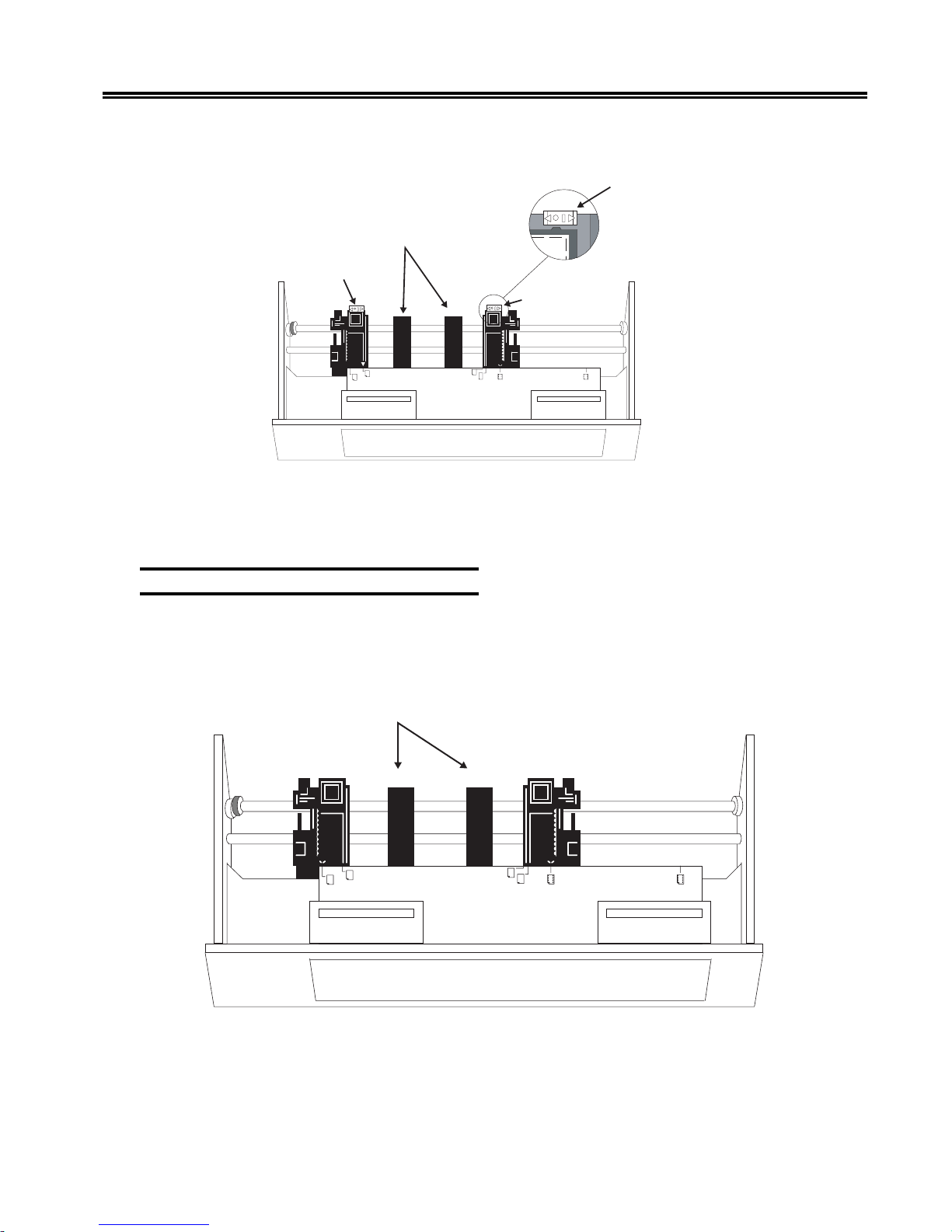
Note: If your Forms Handler module is equipped with the roller drive option, move
both of the white slide bars on the tractors to the left to disengage the roller
2-22 701333-004
Page 37
Preparing to Operate the 1330
drive. The bars will snap into the OFF position, as sho wn in Figure 2-20.
Roller Drive
Shown OFF
Paper Supports
Slide Bar
Slide Bar
Figure 2-20. DOD Option with Roller Drive
Next is the procedure for using the Document Insertion Device (DID) option.
Installing Forms Using the DID Option
Refer to Figure 2-21 for a picture of the Forms Handler module set for the DID option. In
this procedure, first set up the module for forms loading, next insert the module into the
printer, and finally load the forms into the printer.
Paper Supports
Figure 2-21. Forms Handler Module (DID Option)
1. Make sure the printer power is on, and the printer is in Stop mode.
2. For ease of handling, lay the module on top of the printer.
701333-004 2-23
Page 38

Preparing to Operate the 1330
3. Unlock the left forms tractor of the module.
4. Slide the left forms tractor to the left, as far as it will go.
5. Lock the left tractor.
6. Unlock the right forms tractor on the module.
7. Insert a sample of the forms you plan to use into the module slot, making sure that
the left edge of the forms is in contact with the left inside edge of the module.
8. Move the right tractor so that the arrow on the bottom of the tractor points to the
right edge of the forms. Note that two standard widths for sheet feed paper – 8 1/4
inches (21.0 cm) and 8 1/2 inches (21.6 cm) – are marked on the module.
9. Lock the right tractor .
10. Center the paper supports (Figure 2-22) an equal distance from the tractors and
from each other. F or narrow forms, snap out the paper supports.
11. Remove the sample forms.
12. Insert the module into the front of the printer . The display windo w will read DID.
13. Place the forms in the module (see (Figure 2-22) Use the left edge of the module to
help feed the forms in straight. Insert the forms until the top edge contacts both the
right and left feed rollers.
Figure 2-22. Inserting Paper - F orms Handler Module
14. While holding the forms lightly, pr ess the Load/Eject key to mo ve the forms to the
top of form position. Release the forms as the printer slowly advances them.
Note: If the forms are skewed, the printer will reject them, and the message 04 P APER
SKEW will be displayed. Go back to Step 13.
2-24 701333-004
Page 39
Preparing to Operate the 1330
15. Open the printer cover .
16. Adjust the setting of the platen gap lever, as necessary. Move the lever to a lower
setting (toward the platen) for darker print; move the lev er to a higher setting (toward
you) for lighter print. If you are using multipart forms, make sure that the last copy
is legible without any smudging on any other copy . If the last cop y is too light, move
the lever to a lower setting. If the last copy is all right, b ut other copies are smudging,
move the lev er to a higher setting. Note that moving the lev er will affect print head
life.
17. Unlock the 1330 right forms tractor.
18. Position the right tractor for the width of the forms. The arrow on the bottom of the
tractor should point to the right edge of the forms.
19. Lock the right tractor.
20. Close the printer cover .
21. Press the Start key to enable printing.
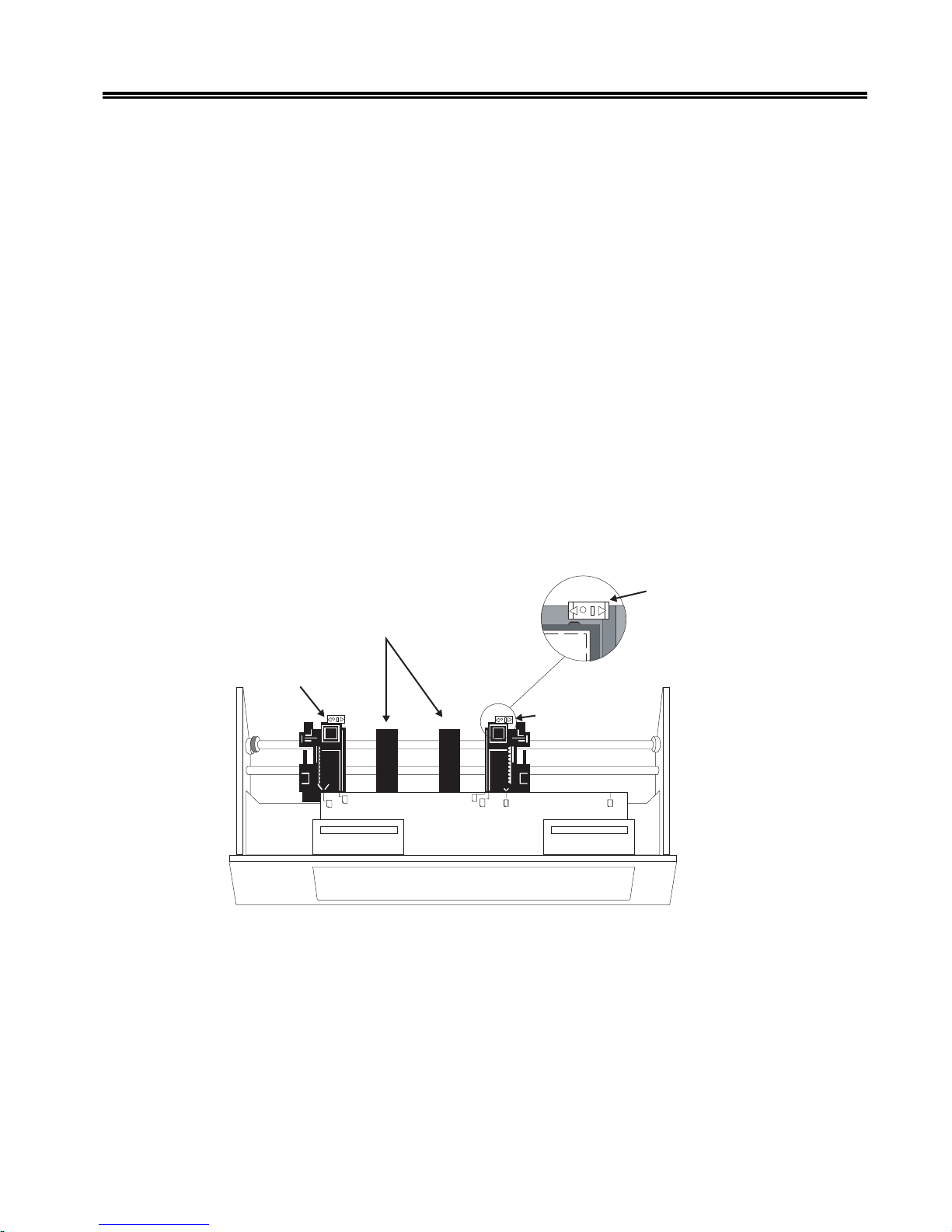
Note: If your Forms Handler module is equipped with the roller drive option, move
both of the white slide bars on the tractors to the right to engage the DID roller
drive. The bars will snap into position, and their right sides will e xtend beyond
the edges in the ON position, as shown in Figure 2-23.
Roller Drive
Shown ON
Paper Supports
Slide Bar
Slide Bar
Figure 2-23. DID Option with Roller Drive
The installation of the 1330 is now complete, and the printer is ready to print.
Before the 1330 can begin normal operations, it must be configured with the featur es and
identification information appropriate for your system. The configuration process is
discussed in Chapter 4 and Chapter 5. Before you configure the 1330, you should be
familiar with the operator control panel and the display window messages, which are
explained in Chapter 3.
701333-004 2-25
Page 40
Chapter 3. Operator Control Panel
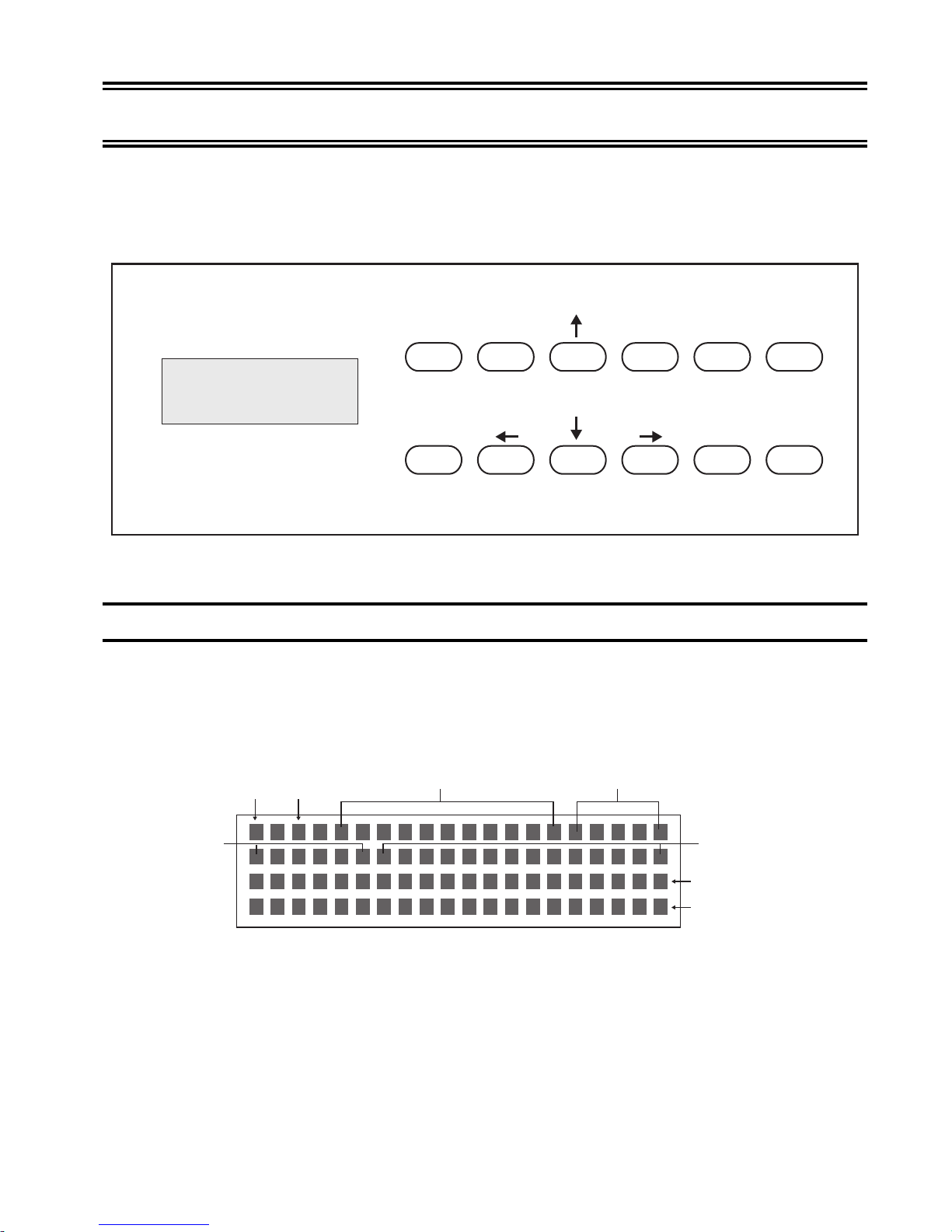
The 1330 Operator Control Panel, located on the front of the printer, consists of the
status display window and the keypad. The status display monitors printer operations,
and the keypad is used to start and control operator functions. See Figure 3-1.
Figure 3-1. 1330 Operator Control Panel
The Status Display
The 80-character status display window , located on the left side of the operator control
panel, indicates the operating mode, the printing formats, and other conditions on the
1330. Several of these messages are explained belo w . (See Figure 3-2 for status display
layout.) Messages that appear during print format operations and configuration are
discussed in Chapters 4 and 5.
Start
Stop
Load/
Eject
Form Feed Line Space
Top of
Form Option
Save
Contrast
Setup
Cancel
Print
S/C/A
CU
EMULATION
MODE
701333-004 3-1
OPERATING MODE
Figure 3-2. Status Display
FORM DEVICE
DATASTREAM
MODE
RESERVED LINE
STATUS MESSAGE
LINE
Page 41

Operator Control Panel
Cu
In 3270 mode or share mode, the Cu signal displays when the 1330 is in communication
with the controller. If the printer is recei ving data, the Cu signal will blink.
S/C/A
The one-letter display indicates the current interface mode the printer is configured with.
The valid displays for the interface option are “S” (share), “C” (3270), and “A” (ASCII).
Operating Mode
The 1330 has four types of operation modes: Start, Stop, Menu, and Contrast.
When the 1330 is in Start mode and ready to receive data, the READ Y message appears
in the status window .
When the printer is in Stop mode and awaiting an operator-initiated function, the ST OP
message appears in the status window . If the printer is left in Stop mode for more than 10
minutes, either a status message is displayed in the window or the printer returns to Start
mode, depending on how you have conf igured the printer .
When the operator is configuring the printer using the front panel option, the printer is in
Menu mode. (See Chapter 4 for displays under the Menu mode.)
When the operator is adjusting the darkness of the print using the Contrast key, the
printer is in Contrast mode. (See Chapter 6 for displays under the Contrast mode.)
Please note that no printing takes place in Stop mode other than operator print. Data
received from the controller will be printed only when the printer is in Ready mode.
Form Device
The form module installed with the printer will be displayed when the printer is configured
to sense the module. If you are using an overwrite feature in the conf iguration option, the
display will show the overwrite value. The form devices available f or the 1330 are “CFD”
(continuous forms device), “DOD” (document on demand), and “DID” (document
insertion device).
Emulation Mode
The current printer emulation modes will be displayed in this location. The available
emulation modes for 3270 are “4230,” “4224,” “3268,” and “2124.” The available
emulation modes for ASCII are Proprinter and TI-810.
3-2 701333-004
Page 42

Datastream Mode/Interface Type
When host data is being processed, the type of datastream will be displayed in this location.
The acceptable datastreams are LU1 (SCS), LU3 (DSC/DSE), LU1-IPDS, and LU3IPDS. In ASCII, the interface type will be displayed. Those types can be parallel, RS232, RS-422, or ASC.
Status Message
The 1330 displays the current printer status in this location. When the 1330 is operated
under normal conditions, no message should be displayed. If an error is detected by the
printer, for example a paper jam, the printer will display PAPER JAM on the status line.
If more than one error is detected at the same time, only the most serious one will be
displayed on the status line. Once the problem is corrected, the status line will clear or
the next error message, if any, will be displayed.
The Keypad
The 1330 keypad, located on the right side of the operator control panel, works on a
pressure sensitive principle. When you press a key , a switch is activ ated that changes the
state or mode of the printer.
Operator Control Panel
When you press an inv alid keypad key , the printer will beep if the alarm is acti vated. The
alarm can be enabled or disabled during configuration. For instructions on how to configure
the alarm in 3270 mode, see Chapter 4, Configuration Options 402 and 403; for ASCII
mode, see Chapter 5, Configuration Options 402 and 403.
Key Functions
Start
Stop
The Start key puts the 1330 in Ready mode if the printer is not in Menu mode. If the
system is sending data to be printed, and no error conditions appear in the display, this
key starts the printer printing. This k ey also stops the printer alarm. If the 1330 is in Stop
mode with the forms ejected in DOD mode, this key will not function until you put the
form back to the normal condition by pressing the Load/Eject key . If the 1330 is in Menu
mode, the Start key will select the current option for configuration.
The Stop key puts the printer in Stop mode when the printer is in Ready or Menu mode.
When running an operator test, the Stop key stops any test after the current line is finished.
In Menu mode, the Stop key also serves as a return from an option to the menu list.
The Stop key also stops the printer alarm, and clears any displayed error conditions,
provided they no longer exist. For e xample, in DOD mode, if the form is ejected and the
cover is opened, the CO VER OPEN message will display . Pressing the Stop key in Stop
mode after the cover is closed will clear the previous COVER OPEN message and put
the original FORMS EJECTED message in the status window .
701333-004 3-3
Page 43
Operator Control Panel
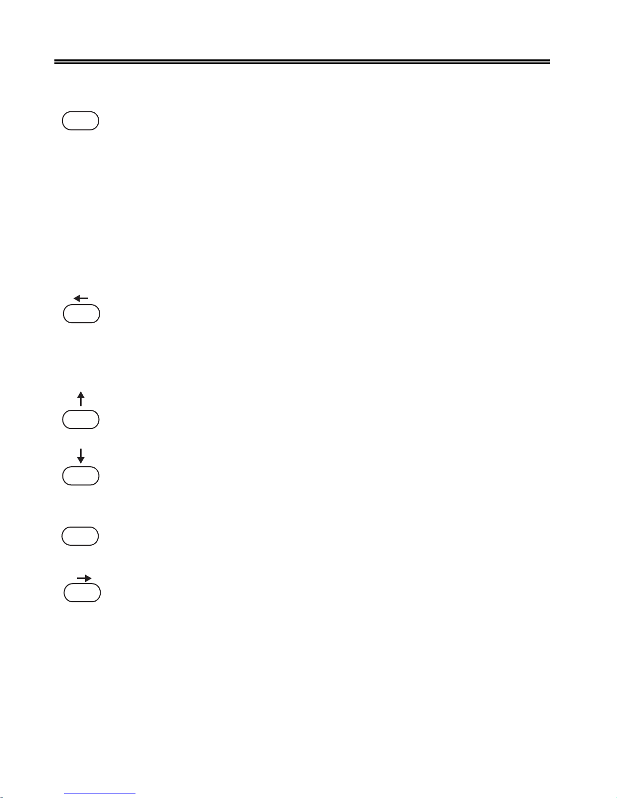
Load/
Eject
Form Feed
With the Document Insertion Device, pressing the Load/Eject key at initial load will
advance the paper to the current position on the form. Pressing the key again will eject
the paper.
With the Document on Demand de vice, pressing the Load/Eject key in Ready mode for
initial load will advance the paper to the first print line. Pressing the ke y a second time
will advance the paper to the tear line and put the printer in Stop mode so that you can
tear the paper off using the tear bar . The status windo w will display the message FORMS
EJECTED. Pressing the Load/Eject key a third time with the form ejected will clear this
message from the display and will move the paper back to the current position on the
form.
The Load/Eject key will work in both Start and Stop modes with the Forms Handler
module. W ith the Continuous Forms Module, if the paper is out, you can press the Load/
Eject key in Stop mode to eject the last sheet of paper .
The Form Feed key (which shares the key with Left Arrow) advances the forms so that
the next form is positioned at the top of form. This function is used only with continuous
forms and the Document on Demand option. Form feed is active only in Stop mode.
In Menu mode, the Left Arrow key scrolls through the available options or tests under
the current menu. After selecting an option, the Left Arrow ke y scrolls through the available
values of that option. The Left Arro w keys is also used to adjust the darkness of the print
in Contrast mode.
Top of
Form
Line Space
The Up and Down Arro w ke ys, in Stop mode, mov e the forms 0.007 inch (0.18 mm) in
the direction of the arrow each time the key is pressed. If the Up Arrow key is held, the
forms move continuously until the key is released. In Menu mode, the Up and Down
Arrow keys are used to scroll through the menu list. T he Up Arrow mo ves forward through
the menu, and the Down Arro w mov es backward through the menu.
Note: If the Continuous Forms module is installed, do not use the Down Arrow key
for continuous forms movement. The forms may become misaligned.
The T op of For m key sets the current position as the first print line on the forms. With the
Document Insertion Device installed and paper not loaded, this key will also cause the
next sheet loaded to begin printing at the first print line. This key is active only in Stop
mode.
The Line Space key (which shares the key with Right Arro w) advances the forms upward
one line. If this key is held for more than 0.5 second, the forms will continue to move
forward until the key is released. The Line Space key is acti ve only in Stop mode.
In Menu mode, the Right Arr ow ke y scrolls through the av ailable options or tests under
the current menu. After selecting an option, the Right Arrow key scrolls through the
available values of that option. The Right Arrow key is also used to adjust the darkness of
the print in Contrast mode.
3-4 701333-004
Page 44

Operator Control Panel
Option
Save
Contrast
Setup
Cancel
Print
The Option key puts the 1330 in Menu mode. In Menu mode you can configur e the 1330
by setting options to the values you want or you can run diagnostic tests to verify the
printer’s performance. This key is acti ve only in Stop mode.
The Save key is only active in Menu mode. It saves the value of the currently selected
option when you are configuring the 1330 from the keypad. The Sav e key is also used to
start a test case under the Diagnostic menu.
The Contrast key in Ready mode enables the operator to get into the Contrast mode
where the operator can manually adjust the print for darkness. For more details, see
Chapter 6.
The Setup key prints a setup line of Hs from the left margin to the right margin. The
Setup key is active in Stop mode and Contrast mode to help the operator verify the
current print format and print contrast.
The Cancel Print key cancels any chained SCS printing currently in process. This k ey is
active only in Stop mode.
701333-004 3-5
Page 45

Chapter 4. Configuring the 1330 in
The configuration process enables you to customize the 1330 to meet your specific
operating needs without assistance from Customer Service. You can also change
configuration parameters at any time without service costs.
The 1330 Operator Control Panel provides access to the configur ation options. Now that
you are familiar with the operator control panel, you are ready to configure the printer .
Review the following summary of the conf iguration process before you begin.
Configuration Procedure
Using the Keys
Here are some general rules for keypad use in Menu mode:
• Press the Option key while in Stop mode to enter Menu mode.
• Press the Up Arro w ke y to scroll forward in the menu list.
3270 Mode
• Press the Down Ar ro w key to scroll backw ard in the menu list.
• Press the Right Arrow to scroll forward in the options list under the current menu and
to scroll forward in the value list under the currently selected option.
• Press the Left Arrow to scroll backward in the options list under the current menu and
to scroll backward in the value list under the currently selected option.
• Press the Start key to select the current option.
• Press the Stop key to exit from a selected option or Menu mode.
• Press the Save ke y to activ ate a c hoice for the currently selected option.
Getting into the Menu Mode
Y ou m ust get into the Menu mode when you want to configure the 1330. The procedure
for getting into the Menu mode is as follows:
1. Press the Stop key when the printer is in Ready mode.
2. Press the Option key to put the printer into the Menu mode. (If you do not have the
optional dual interface board installed in your printer, go to Step 4.)
701333-004 4-1
Page 46

Configuring the 1330 in 3270 Mode
3. If the optional dual interface board is installed in your printer, the status display will
give you the option of pressing the Start key for the 3270 menu or pressing the Stop
key for the ASCII menu. At this point you may select one of the two menus to enter
or press the Cancel key to quit and return the printer to the Ready mode.
4. Y ou are no w in the Menu mode. Y ou will see the f irst menu of the menu list displayed
on the first line of the status display and the first option of that menu displayed on
the second line of the status display . There may be some abbreviation of the menu
name or its option in order to make it fit on the 20-character display .
Scrolling Through Menu Selections
You can find a specific option under a specific menu by using the arrow keys in the
following ways:
• Use the Up Ar ro w key to sequentially scroll forward through the menu list.
• Use the Down Arro w ke y to sequentially scroll backward through the menu list.
Every time an Up Arrow or Down Arro w key is pressed, you will see changes on the first
line of the status display . When the Main menu changes, the default option is automatically
changed to list the first available option in the option list under the current menu.
• Use the Right Arrow key to sequentially scroll forward through the options list under
the current menu.
• Use the Left A rrow key to sequentially scroll backw ard through the options list under
the current menu.
Every time a Right Arrow or Left Arrow key is pressed, you will see changes on the
second line of the status display . The f irst line of the status display will not change.
All of the arrow keys ha ve a loopback featur e that enables you to automatically start at
the top of a list once you have gotten to the end. See the tree chart on the following page
for the choices in the menu list and all the options under each menu.
T o run a test case, follo w this procedure:
• Press the Save ke y to run the current test displayed under the Diagnostic menu on the
display . A POR will occur once you e xit the Menu mode.
• Press the Stop key to stop a running test case.
4-2 701333-004
Page 47
Future Use
Reserved for
Diagnostic
900
Vital Product
800
Program
700
Extended
Data
Symbol
Keypad
901 Serial Number
902 Device Specification Information
701 Print Configuration
702 Quick Reference
703 Set Factory Default
704 POR Custom Set
705 Save Cust Set
706 Recall Cust Set
707 Display Character Count
708 PA1
709 PA2
Configuring the 1330 in 3270 Mode
801 Programmed Symbols
802 Reserved for future use
803 Reserved for future use
804 APA Print Direction
710 Buffer Reprint
600
Attachment
601 Interface
602 Idle Timeout
3270 Menu
500
501 Printer Emulation Mode
502 Buffer Size
503 2124 Escape Character
Communication
400
Printer Setup
300
Compatibility
200
Quality
Font & Print
504 Early Print Complete
301 Carriage Return at MPP+1
302 New Line at MPP+1
303 Null Suppression
304 Form Feed Follows
305 Form Feed with Auto New Line at Print End
306 Midline Form Feed
401 Operator Format
402 Key Alarm
307 Form Feed Print with a Space
308 Formatted Print
309 Bar Code Control
310 Base Color
311 Attribute Highlight
312 Ignore SCS Commands
403 Alarm on Error
404 Print Head Style
405 Print Head Column Spacing
406 Ribbon Type Override
407 Ribbon Track Select Adjustment
408 Module Type Override
409 Automatic Form Eject
410 Full Form Feed Eject
411 Paper Eject Adjustment
412 Horizontal Offset
413 Horizontal Registration
414 Paper Jam Sensor Enable
415 Paper Out Sensor Enable
416 Paper Skew Sensor Enable
418 DOD Load Adjust
419 DID Load Adjust
420 Stop Mode Timeout
422 Start Mode After Eject
423 Report Intervention
100
Page Format
701333-004 4-3
101 Left Margin
102 CPI
103 LPI
104 MPP
105 Form Length
106 Line Spacing
107 Set Media
201 Language
202 Display Language
203 Mono/Dual Case
204 Bold Print
205 Bidir 2 Pass Prt
206 Print Quality
207 Host Fast Draft
208 Test Orientation
209 Dotted Zero
210 Graphics Density
Page 48

Configuring the 1330 in 3270 Mode
Selecting a Menu Option
When the target menu appears on the first line of the status display , you can get into that
option and configure the printer by changing the value of that option. F ollow these steps:
1. To select an option, press the Start ke y when the option you want to change appears
on the second line of the status display. Once an option is selected, the originally
saved value of that option will appear on the third line of the status display.
2. Press the Left Arrow and Right Arrow keys to move through the list of available
values for that option.
3. If you want to change the value of the selected option, press the Save key while the
desired value appears on the status display . (An asterisk at the beginning of the third
line of the display indicates the currently saved value for the selected option.)
4. Press the Stop key to exit the selected option.
Note: You will not be able to move to the next option or to another menu until you
have exited the currently selected option.
Leaving Menu Mode
You can exit the Menu mode by pressing the Stop key until the READY message is
displayed.
4-4 701333-004
Page 49
The Configuration Options
The chart on Page 4-3 provides you with a list of the configuration options for the 1330
in 3270 mode.
This section defines the options in each menu.
100 Page Format
The following options define the printer’ s page format.
101 – Left Margin
Configuration Option 101 enables you to specify a left margin value for LU3 mode . This
value is the first possible print position. Valid values are 1 through 20. The def ault is 1.
Note: Use this configuration option to adjust the left margin v alue in LU3 mode only .
For LU1 operations, use Configuration Option 412 to change the leftmost
printable position or first printable position. Note that Option 412 settings are
effective in all print modes.
Configuring the 1330 in 3270 Mode
Note that specifying a left margin value greater than 1 effecti vely decreases the number
of characters you can specify as a line length. For example, at 10 characters per inch
(CPI), 132 is the maximum print position (MPP) on the print line. If you specify a left
margin value of 15, the print line length will be a maximum of 118 characters (at 10
CPI).
See the chart below for the MPP that corresponds to each CPI selection.
PPM IPC
23101
85121
89151
0227.61
5221.71
46202
T o specify a left margin value, follo w the configuration procedure that begins on Page 4-1.
When you have made your selection, press Sav e to activ ate your changes.
701333-004 4-5
Page 50

Configuring the 1330 in 3270 Mode
102 – Characters per Inch (CPI)
Use Configuration Option 102 to specify the number of characters per inch that the 1330
will print.
noitpO eciohC gninaeM
1)tluafed(IPC01
2IPC21
201
Note: When you select 16.7 CPI or 20 CPI, the printing defaults to Data Processing
(draft) quality .
To specify your choice, follow the configuration procedure that begins on Page 4-1.
Enter your choice (1, 2, 3, 4, 5, or 6) and press Save to activ ate your changes.
If an INVALID message is displayed when you change the CPI, first change the MPP
setting using Configuration Option 104, then change the CPI.
3IPC51
4IPC7.61
5IPC1.71
6IPC02
103 – Lines per Inch (LPI)
Use Configuration Option 103 to specify the lines per inch that the 1330 will print.
noitpO eciohC gninaeM
1)tluafed(IPL6
301
2IPL8
To specify your choice, follow the configuration procedure that begins on Page 4-1.
Enter your choice (1, 2, or 3) and press Save to activ ate your changes.
Note: For printing at 3 LPI or 4 LPI, refer to Option 106.
Note: LPI is checked for validity by forms length Option 105. If the forms length is
too great for the LPI selected, then the LPI is invalid.
4-6 701333-004
3)ylnosesoprupgnitsetrof(IPL441
Page 51

Configuring the 1330 in 3270 Mode
104 – Maximum Print Position (MPP)
Configuration Option 104 enables you to specify a maximum print position (MPP) value.
This value is the print position of the last character on the print line. The MPP range is
based on the following MPP-CPI chart. V alid values ar e 1 through the value shown in the
chart for each CPI. The default is 132.
PPM IPC
23101
85121
89151
0227.61
5221.71
46202
To specify an MPP value, follow the configuration procedure that begins on Page 4-1.
You can enter a different choice, or you can keep the current value by pressing Save.
If an Inv alid message is displayed when you change the MPP , f irst change the CPI setting
using Configuration Option 102, then change the MPP.
105 – Form Length
Configuration Option 105 enables you to specify the number of lines per page that the
1330 will print. Valid values are 0 through 660 for 6 LPI and 0 through 880 for 8 LPI. The
values are based on a maximum allowable form length of 110 inches.
T o specify the forms length, follow the conf iguration procedure that begins on Page 4-1.
You can enter a different value, or you can keep the current value by pressing Save.
106 – Line Spacing
Use Configuration Option 106 to specify whether the 1330 will print double line spacing.
Refer to “103 – Lines per Inch (LPI)” above for information on Option 103.
noitpO eciohC gninaeM
)elgniS(1eht,sitaht;301noitpOnideificepssaIPL
601
)elbuoD(2eht,sitaht;2ybdedivid301noitpOsiIPL
IPL4roIPL3tastnirp0331
)tluafed(IPL8roIPL6tastnirp0331
To specify your choice, follow the configuration procedure that begins on Page 4-1.
Enter your choice (1 or 2) and press Save.
701333-004 4-7
Page 52
Configuring the 1330 in 3270 Mode
107 – Force Set Media Size
With Configuration Option 107, in IPDS mode, you can choose to unconditionally honor
the Set Media Size command. If you choose 0 (disable), the page size will be the smaller
of the operator panel settings and the Set Media Size values.
noitpO eciohC gninaeM
31
To specify your choice, follow the configuration procedure that begins on Page 4-1.
Enter your choice (0 or 1) and press Save.
200 Font & Print Quality
The following options define the printer’s font and print quality .
201 – Language
Configuration Option 201 enables you to select the language character set for the 1330.
Note that the selected language character set does not become active until after the ne w
configuration values hav e been saved and the conf iguration sequence ended.
noitpO eciohC gninaeM
102
)elbasiD(0
)elbanE(1yllanoitidnocnueziSaideMteSronoH
1)tluafed(hsilgnESU
2namreG/nairtsuA
3etanretlAnamreG/nairtsuA
4naigewroN/hsinaD
5etanretlAnaigewroN/hsinaD
6hsidewS/hsinniF
7etanretlAhsidewS/hsinniF
8hcnerF
9nailatI
01etanretlAeseugutroP
11hsinapS
21etanretlAhsinapS
31KUhsilgnE
41naigleB
51nailizarB
61hsilgnEesenapaJ
71gnikaepShsinapS
rotareponehwylnoeziSaideMteSronoH
)tluafed(retaergerasgnitteslenap
4-8 701333-004
Page 53

noitpO eciohC gninaeM
815teSlanoitanretnI
911teSlanoitanretnI
02anakataKesenapaJ
12eseugutroP
22laugniliBssiwS
32501ytrezAhcnerF
42hcnerFnaidanaC
52laugniliBnaidanaC
62cibarA
72)elbitapmoc-4224MBI(TLBwerbeH
82weNwerbeH
102
92dlOwerbeH
03iahT
13hsikruT
23A-RCO
33B-RCO
43cidnalecI
53ECEOR/nitaL
63cilliryC
73keerGweN
83keerGdlO
93valsoguY
04gniwarDeniL
Configuring the 1330 in 3270 Mode
To select a language character set, follow the configuration procedure that begins on
Page 4-1. You can select another language character set by entering its corresponding
number, or you can keep the cur rent selection by pressing Sav e.
202 – Display Language
Use Configuration Option 202 to select a specific country language to display messages.
The languages available for the option are English (default), French, and German. Some
domestic units support only English.
To select a language character set, follow the configuration procedure that begins on
Page 4-1.
701333-004 4-9
Page 54
Configuring the 1330 in 3270 Mode
203 – Mono/Dual Case
Configuration Option 203 enables you to specify whether the 1330 will print in mono
case (all characters uppercase) or dual case (characters uppercase and lowercase) in LU3
mode.
noitpO eciohC gninaeM
1esacreppunidetnirperasretcarahclla–esaconoM
302
To specify your choice, follow the configuration procedure that begins on Page 4-1.
Enter your choice (1 or 2) and press Save.
204 – Bold Print Enable
Use Configuration Option 204 to enable or disable bold print. If you specify YES (by
entering 1), bold print will be enabled.
2esacreppunitnessadetnirperasretcarahc–esaclauD
)tluafed(esacrewoldna
noitpO eciohC gninaeM
402
To specify your choice, follow the configuration procedure that begins on Page 4-1.
Enter your choice (0 or 1) and press Save.
)oN(0)tluafed(delbasidsitnirpdloB
)seY(1delbanesitnirpdloB
205 – Two-Pass Print Direction
Use Configuration Option 205 to better align the two print head passes on printing that
requires two passes. This option could be useful during subtractive color printing.
With Choice 1, the print head will make two unidirectional passes. With Choice 2, the
print head will make one bidirectional pass. Choice 1 will give you truer , crisper colors
on the printout; however, throughput will be reduced, and Choice 2 will give faster
operation.
noitpO eciohC gninaeM
502
1sessaplanoitceridinuowtsekamdaehtnirpehT
2)tluafed(ssaplanoitceridibenosekamdaehtnirpehT
To specify your choice, follow the configuration procedure that begins on Page 4-1.
Enter your choice (1 or 2) and press Save.
4-10 701333-004
Page 55
Configuring the 1330 in 3270 Mode
206 – Print Quality
With Configuration Option 206, you can choose print quality.
noitpO eciohC gninaeM
1)tluafed(ytilauq)PD(gnissecorpataD
602
To select the print quality, follow the configuration procedure that begins on Page 4-1.
Enter your choice by pressing the appropriate number key (1, 2, 3, or 4), or you can keep
the current print quality by pressing Save.
2ytilauq)txetPD(txetgnissecorpataD
3)QLN(ytilauqrettelraeN
4)DF(tfardtsaF
207 – Host Fast Draft
Configuration Option 207 enables you to select the lowest print quality a vailable through
the datastream. The default is Disabled.
noitpO eciohC gninaeM
0
702
1
To specify your choice, follow the configuration procedure that begins on Page 4-1.
Enter your choice (0 or 1) and press Save.
edomtfarDtsaFsi
)tluafed(edomPDsimaertsatad
ehthguorhtelbaliavaytilauqtnirptsewoL–delbasiD
maertsatadehthguorhtelbaliavaytilauqtnirptsewoL
208 – Text Orientation
Configuration Option 208 enables you to manually select the direction that text will be
printed. The default is left to right.
noitpO eciohC gninaeM
802
To specify your choice, follow the configuration procedure that begins on Page 4-1.
Enter your choice (0 or 1) and press Save.
Note: Option 208 will only appear if the A rabic or Hebrew Print Language is selected
in Option 201.
701333-004 4-11
)thgirottfel(0)tluafed(thgirottfeltnirP
)tfelotthgir(1tfelotthgirtnirP
Page 56
Configuring the 1330 in 3270 Mode
209 – Dotted Zero
Use Configuration Option 209 to specify whether a dotted zero should be printed when
a zero is selected. If you specify NO, the dotted zero will not be used.
noitpO eciohC gninaeM
902
To specify your choice, follow the configuration procedure that begins on Page 4-1.
Enter your choice (0 or 1) and press Save.
Note: When you request OCR-A, OCR-B, APL, or printing an y fonts in diagnostics,
the printer will use the undotted zero, regardless of the operator panel selection.
)oN(0)tluafed(desuebtonlliworezdettodehT
)seY(1desueblliworezdettodehT
210 – Graphics Density
Use Configuration Option 210 to specify the Graphics Density mode. Low density graphics
enables printing to switch from 144 (high) to 72 (low) dots per inch, thus moving the
print head at a faster rate.
noitpO eciohC gninaeM
0scihpargytisnedwol/edocrabtsartnocwoL
1)tluafed(scihpargytisnedhgih/edocrabtsartnochgiH
012
2scihpargytisnedwol/edocrabtsartnochgiH
3scihpargytisnedhgih/edocrabtsartnocwoL
4maertsatadnideificepsytisned–edomdetcelestsoH
To specify your choice, follow the configuration procedure that begins on Page 4-1.
Enter your choice (0, 1, 2, 3, or 4) and press Save.
Note: This option is valid only in IPDS mode. Your choice will override any value
from the application program (unless you select Value 4).
4-12 701333-004
Page 57

300 Compatibility
The following options define the printer’ s compatibility .
301 – Carriage Return (CR) at MPP + 1
Configuration Option 301 allows you to choose whether the printer will do a carriage
return (CR) after the maximum print position (MPP) of a print line has been exceeded.
noitpO eciohC gninaeM
Configuring the 1330 in 3270 Mode
)oN(0
103
)seY(1
To specify your choice, follow the configuration procedure that begins on Page 4-1.
Enter your choice (0 or 1) and press Save.
)tluafed(eniltxeneht
rucconacgnitnirprevotahtos,enilemaseht
302 – New Line (NL) at MPP + 1
Use Configuration Option 302 to specify whether the print head will move one new line
(NL) or two new lines after the maximum print position (MPP) of a print line has been
exceeded.
noitpO eciohC gninaeM
)oN(0
203
)seY(1
To specify your choice, follow the configuration procedure that begins on Page 4-1.
Enter your choice (0 or 1) and press Save.
eniltxeneht
)tluafed(eniltxenehtretfaenileht
no1noitisopotdaehtnirpehtsevom1+PPMtaRC
no1noitisopotdaehtnirpehtsevom1+PPMtaRC
no1noitisopotdaehtnirpehtsevom1+PPMtaLN
no1noitisopotdaehtnirpehtsevom1+PPMtaLN
303 – Null Suppression
Use Configuration Option 303 to specify how the printer will handle null characters.
This option is valid for LU3 mode only .
noitpO eciohC gninaeM
303
To specify your choice, follow the configuration procedure that begins on Page 4-1.
Enter your choice (0 or 1) and press Save.
701333-004 4-13
)oN(0sllunfoenileritnerofdeefenilseoD
)seY(1
foenileritnerofdegnahcnusniamernoitisoptnirP
)tluafed(sllun
Page 58
Configuring the 1330 in 3270 Mode
304 – Form Feed (FF)
Use Configuration Option 304 to specify if the 1330 will perform a form feed (FF)
operation before or after a local print, after an LU3 print, or never .
noitpO eciohC gninaeM
1
2tnirplacolretfaFF
403
To specify your choice, follow the configuration procedure that begins on Page 4-1.
Enter your choice (1, 2, 3, 4, or 5) and press Save.
3tnirp3ULretfaFF
4tnirplacolerofebFF
5tnirplacolretfadnaerofebFF
)tluafed(
305 – Form Feed with Auto New Line at Print End
Use Configuration Option 305 to specify whether, after a print, the 1330 will mov e the
print head to the first line or second line of the next page.
noitpO eciohC gninaeM
)oN(01retcarahc,1enilmroffopototdaehtnirpehtsevoM
503
)seY(1
)tluafed(
)tnirp3ULotdeddaFFoN(tnirpswollofFFoN
1retcarahc,2enilmroffopototdaehtnirpehtsevoM
To specify your choice, follow the configuration procedure that begins on Page 4-1.
Enter your choice (0 or 1) and press Save.
306 – Midline Form Feed (FF)
Configuration Option 306 is used to specify whether to use the midline form feed (FF)
feature, which allows the form feed character to be placed in any position on a print line.
noitpO eciohC gninaeM
603
To specify your choice, follow the configuration procedure that begins on Page 4-1.
Enter your choice (0 or 1) and press Save.
)oN(0)tluafed(1noitisoptaylnoFF
)seY(1PPMot1morfnoitisopynataFF
4-14 701333-004
Page 59

Configuring the 1330 in 3270 Mode
307 – Form Feed (FF) Printed with a Space
Use Configuration Option 307 to specify whether the print head will move to the first
character position or second character position on the next top of form (TOF).
noitpO eciohC gninaeM
703
To specify your choice, follow the configuration procedure that begins on Page 4-1.
Enter your choice (0 or 1) and press Save.
)oN(01retcarahc,FOTtadaehtnirpehtstuP
)seY(1)tluafed(2retcarahc,FOTtadaehtnirpehtstuP
308 – Formatted Print
Configuration Option 308 allows you to select the forma tted print override, a feature that
honors certain format commands in spite of a formatted print request from the host CPU.
Carriage Return, End of Message, and New Line commands are acti ve, and null lines are
not suppressed. The host CPU defined line length is honored. To activate the formatted
print override feature, select 1.
noitpO eciohC gninaeM
)oN(0egasseMfodnEdna,nruteRegairraC,eniLweN
803
)seY(1egasseMfodnEdna,nruteRegairraC,eniLweN
detucexeera
To specify your choice, follow the configuration procedure that begins on Page 4-1.
Enter your choice (0 or 1) and press Save.
)tluafed(detnirpsiecapsa–derongiera
309 – Bar Code Control
Use Configuration Option 309 to configure the bar code printout in 2124 emulation
mode.
noitpO eciohC gninaeM
903
701333-004 4-15
1tnofedocrab4212dradnatsehtsesU–dradnatS
)tluafed(retnirpehtni
2rellamsaottnofsesserpmoC–tnoFdesserpmoC
.elbaliavasi9fo3edocrabylnoyltnerruC.ezis
tonsitnofdesserpmocedocrabtnerrucehtnehW
.ezisdradnatsottluafed,elbaliava
3ehtotresolcebotpuIRHsevoM–IRHresolC
lliwIRH,eulavsihtotderugifnocnehW.edocrab
fi,tnofdesserpmocehtesuyllacitamotua
.tnofdradnatssesu,elbaliavatonfI.elbaliava
Page 60
Configuring the 1330 in 3270 Mode
This option shall not have any ef fect in IPDS bar code printing.
To specify the bar code control default, follow the configuration procedure that begins
on Page 4-1. Enter your choice (1, 2, or 3) and press Save.
310 – Base Color
Use Configuration Option 310 to specify whether the base color of the printed text defaults
to green or black when you power on the printer . The controller can ov erride the operator
field attribute enable/disable setting.
noitpO eciohC gninaeM
1delbaneerasetubirttadleifdnakcalbsirolocesaB
)tluafed(
013
T o specify the base color default, follow the conf iguration procedure that begins on Page
4-1. Enter your choice (1, 2, 3, or 4) and press Save.
2delbasiderasetubirttadleifdnakcalbsirolocesaB
3delbaneerasetubirttadleifdnaneergsirolocesaB
4delbasiderasetubirttadleifdnaneergsirolocesaB
311 – Attribute Selectable Highlighting
Use Configuration Option 311 to choose attribute selectable normal operation, bolding,
or underscore.
In LU1, when bolding is selected, the attributes that normally control underscore will
control bold instead. Underscore will never be changed. This includes resetting attrib utes
at first in chain or only in chain: bold will be reset and underscore will not be changed.
In LU1, when underscore is selected, operation is identical to normal operation.
In LU3 with a color ribbon, when bolding is selected, character attributes and extended
field attributes normally controlling underscore will control bold instead. Underscore
will never be changed.
In LU3 with a color ribbon, when underscore is selected, operation is identical to normal
operation.
In LU3 with a monochrome ribbon, operation is identical to that of LU3 with a color
ribbon, with this addition: when bold or underscore is selected, the field attributes will
control bolding or underscore.
4-16 701333-004
Page 61

noitpO eciohC gninaeM
0)tluafed(noitarepolamroN
Configuring the 1330 in 3270 Mode
113
To specify your choice, follow the configuration procedure that begins on Page 4-1.
Enter your choice (0, 1, or 2) and press Save.
312 – Ignore SCS Commands
When enabled, Configuration Option 312 will cause the printer to ignore the Set Line
Density and the Set Page Density commands.
noitpO eciohC gninaeM
213
400 Printer Setup
The following options define the printer setup.
401 – Operator Format
1gnidloB
2erocsrednU
elbanEsdnammocSCSerongI
elbasiDsdnammocSCStpeccA
Configuration Option 401 lets you specify a default print format or an operator selected
print format. The 1330 normally po wers on with all printer format parameters set to their
front panel values. However, you can specify that the 1330 power on with the default
printer format values.
The default printer format values are these:
• Lines per inch (LPI) = 6
• Maximum print position (MPP) = 132 (136 for ASCII)
• Maximum page length (MPL) = 66
• Characters per inch (CPI) = 10
• Line spacing = Single
• Case = Dual
• Left margin = 1
• Base color = 1
Note: For IPDS defaults, see Appendix B of this manual.
701333-004 4-17
Page 62

Configuring the 1330 in 3270 Mode
If you choose an operator selected print format for Option 401, the last value saved for
each parameter becomes the new default value when the printer is powered on.
noitpO eciohC gninaeM
104
To specify your choice, follow the configuration procedure that begins on Page 4-1.
Enter the your choice (1 or 2) and press Save.
1tamroftluafeD
2)tluafed(tamrofdetcelesrotarepO
402 – Key Alarm
Use Configuration Option 402 to specify whether a beep will sound each time a key on
the touchpad is pressed. If you specify NO (by entering 0), the touchpad will not produce
audible feedback.
noitpO eciohC gninaeM
204
To specify your choice, follow the configuration procedure that begins on Page 4-1.
Enter your choice (0 or 1) and press Save.
)oN(0)tluafed(desserpsiyekanehwdnuostonseodmralaehT
)seY(1desserpsiyekanehwsdnuosmralaehT
403 – Alarm on Error
Use Configuration Option 403 to specify whether an alarm will sound when an error
occurs. If you specify NO (by entering 0), the alarm will not sound.
noitpO eciohC gninaeM
)oN(0sruccororrenanehwdnuostonseodmralaehT
304
To specify your choice, follow the configuration procedure that begins on Page 4-1.
Enter your choice (0 or 1) and press Save.
)seY(1llatonhguoht(sruccororrenanehwsdnuosmralaehT
)tluafed()mralaehtdnuoslliwsrorre
404 – Print Head Style
When you change the print head, you must inform the 1330 which print head style is
currently installed by using this configuration option.
Caution
Failure to enter the correct print head style under Option 413 can result in poor print head
performance and damage to the print head.
4-18 701333-004
Page 63

Configuring the 1330 in 3270 Mode
Before specifying the print head style, turn the printer off. Refer to the label on the print
head to determine which style of print head is installed. If you are installing a new print
head, see “Replacing the Print Head” in Chapter 7 of this manual for instructions.
After you have determined the style of print head currently in use, tur n the 1330 back on.
To inform the printer of the print head style, follow the configuration procedure that
begins on Page 4-1. Use the chart below to determine your print head style.
noitpO eciohC gninaeM
404
If the correct print head style number is displayed, press Save. If the number does not
correspond to the print head style, enter the correct number (1 or 2) and press Save.
405 – Print Head Column Spacing
Configuration Option 405 enables you to correct for spacing variations between the banks
of print wires on the print head. If the dots in a vertical column of a character symbol
appear to be misaligned, Option 405 can be used to correct this condition. Valid values
range from 90 to 100. The default is 95. Refer to “Checking Character W idth” in Chapter
7 for complete instructions.
1)tluafed(dellatsnisi1elytsdaehtnirP
2dellatsnisi2elytsdaehtnirP
•
•
•
•
•
•
•
•
•
•
•
•
•
•
•
•
Figure 4-1. Aligned and Unaligned Dots in Characters
406 – Ribbon Type Override
Configuration Option 406 enables you to override the type of ribbon installed in the
printer.
701333-004 4-19
tcerroCtcerrocnI
Page 64

Configuring the 1330 in 3270 Mode
noitpO eciohC gninaeM
0)tluafed(edirrevoon–rosnesepytnobbiresU
604
In normal operation, the default should be used. The other choices enable the printer to
be used with a faulty ribbon or ribbon sensor. The other choices are not recommended
unless the ribbon or sensor is faulty.
To specify your choice, follow the configuration procedure that begins on Page 4-1.
Enter your choice (0, 1, 2, or 3) and press Save.
1nobbir)roloc-4(tnecca–epytnobbiredirrevO
2nobbir)roloc-8(evitcartbus–epytnobbiredirrevO
3nobbiremorhconom–epytnobbiredirrevO
407 – Ribbon Track Select Adjustment
Configuration Option 407 enables you to adjust the home position of the ribbon track
select mechanism. If the printout is showing a color mix, Option 407 can be used to
correct this condition. Valid values are 0 through 10. The default is 5.
T o adjust the home position, follow the configur ation procedure that begins on Page 4-1.
407 TRAK SEL ADJ will display in the status window , followed by the current v alue. If
the printout has a color mix at the top of the characters, enter a lesser value. If the pr intout
shows a color mix at the bottom of the characters, enter a greater value. You can keep the
current value by pressing Save.
408 – Module Type Override
Configuration Option 408 enables you to override the type of forms module installed in
the printer. Y ou can enter 0 to disable the ov erride and use the module sensor. Or you can
choose to override the Document Insertion Device (DID) option, the Document on
Demand (DOD) option, or the Continuous Forms module.
noitpO eciohC gninaeM
0)tluafed(edirrevoon–rosneseludomesU
804
In normal operation, the default should be used. The other choices enable the printer to
be used with a faulty module or sensor. The other choices are not recommended unless
the module or sensor is faulty .
To specify your choice, follow the configuration procedure that begins on Page 4-1.
Enter your choice (0, 1, 2, or 3) and press Save.
1eludomsmroFsuounitnoCehtedirrevO
2noitpoDODehtedirrevO
3noitpoDIDehtedirrevO
4-20 701333-004
Page 65

Configuring the 1330 in 3270 Mode
409 – Auto Eject
T o make it easy for you to tear of f forms, configuration Option 409 enables you to have
an automatic form eject after the 1330 has been idle in DOD mode for an operator
selectable time period. After additional data is received, the form will be r etracted. If you
choose 0 (Disabled), the auto eject will not function.
noitpO eciohC gninaeM
904
To specify your choice, follow the configuration procedure that begins on Page 4-1.
Enter your choice (0 or 1-255) and press Save.
)delbasiD(0)tluafed(atadfodneehttaruccotonlliwtcejemroF
)sdnoceS(552-1ytpmesireffubehtretfasdnocesnruccolliwtcejemroF
410 – Full Form Feed Eject
Configuration Option 410 is used to specify whether to use the full form feed eject feature,
which ejects the form from the print head to the tear point in DOD mode.
noitpO eciohC gninaeM
)oN(0)tluafed(tcejelamroN
014
To specify your choice, follow the configuration procedure that begins on Page 4-1.
Enter your choice (0 or 1) and press Save.
Note: You can select 1 in any mode. However , if the printer is not in DOD mode, the
alarm will sound to alert you that the selection will not be effective until the
printer is put in DOD mode.
)seY(1sitcejeDODa,desserpsiyektcejE/daoLehtnehW
mrofehtfodneehtlitnudeyaled
411 – Paper Eject Adjustment
T o align the forms for easy tear off, conf iguration Option 411 is used in conjunction with
the DOD Forms Handler module. This option enables you to adjust the distance the
paper moves when you press the Load/Eject key while the DOD option is installed. Valid
values are 0 through 255. The default is 127.
To adjust the paper eject distance, follow the configuration procedure that begins on
Page 4-1. EJECT ADJUST will display in the status window, followed by the current
value. If you enter a greater value, the paper will eject higher . If you enter a lesser v alue,
the paper will eject lower . Y ou can k eep the current v alue by pressing Sav e.
701333-004 4-21
Page 66
Configuring the 1330 in 3270 Mode
412 – Horizontal Offset
Use Configuration Option 412 to set the first printable position on the page. V alues r ange
between 0 and 127. Units are in increments of 0.007 inch (0.02 cm), so the offset is
between 0 and 0.88 inch (0 to 2.24 cm). The default is 14.
To specify your choice, follow the configuration procedure that begins on Page 4-1.
Enter your choice (from 0 to 127) and press Save.
Note: If you go to this feature frequently , you may want to use a shortcut to its options.
Follow this procedure: In Ready mode press the Option ke y . That will take you
to Express 412, where you can use the arrow keys to select the values as you
normally would. Once you have chosen the values you want, press the Start ke y
and your setup will be saved.
413 – Horizontal Registration
Configuration Option 413 enables you to adjust the printed line horizontally for vertical
character alignment. Values range between 0 and 255. The default is 127. Units are in
increments of 0.0007 inch (0.002 cm). Note that this option is used with bidirectional
printing only . For complete instructions, refer to “Checking Print Registration” in Chapter 7.
414 – Paper Jam Sensor Enable
Use Configuration Option 414 to enable or disable the paper jam sensor . If you specify
NO (by entering 0), the paper jam sensor will be disabled.
noitpO eciohC gninaeM
414
To specify your choice, follow the configuration procedure that begins on Page 4-1.
Enter your choice (0 or 1) and press Save.
)oN(0delbasidsirosnesmajrepapehT
)seY(1)tluafed(delbanesirosnesmajrepapehT
415 – Paper Out Sensor Enable
Configuration Option 415 enables and disables the paper out sensor. If the paper out
sensor is disabled, the alarm is prevented from sounding when the printer is out of pa per.
Caution
When the paper out sensor is disabled, the printer will not be able to detect a paper out
condition. If the printer continues printing without paper for an extended period, the
print head could be damaged.
4-22 701333-004
Page 67
noitpO eciohC gninaeM
Configuring the 1330 in 3270 Mode
514
To specify your choice, follow the configuration procedure that begins on Page 4-1.
Enter your choice (0 or 1) and press Save.
)oN(0delbasidsirosnestuorepapehT
)seY(1)tluafed(delbanesirosnestuorepapehT
416 – Paper Skew Sensor Enable
Use Configuration Option 416 to enable or disable the paper skew sensor . If you specify
NO (by entering 0), the paper skew sensor will be disabled.
noitpO eciohC gninaeM
614
To specify your choice, follow the configuration procedure that begins on Page 4-1.
Enter your choice (0 or 1) and press Save.
)oN(0delbasidsirosnesweksrepapehT
)seY(1)tluafed(delbanesirosnesweksrepapehT
418 – DOD Load Adjust
Use Configuration Option 418 to set the distance between the top of the form and the
bottom of the characters in the first print line. Values range from 20 to 255, in .007-inch
increments.
For example, if you have a box you want to print in as the first print line, measure the
distance from the physical top of the form to the line you want to print on. Con vert the
distance to .007 inches and enter the distance as the value for the Load Adjust parameter .
Note that you will only be able to access the option that corresponds to the device you
have in the printer; that is, if you hav e a DOD device, the menu will only allow you to
access the DOD Load Adjust option.
Loads can be initiated in Stop or Ready mode with a DID device, but only in Ready
mode with a DOD device.
419 – DID Load Adjust
Use Configuration Option 419 to set the distance between the top of the form and the
bottom of the characters in the first print line. Values range from 20 to 255, in .007-inch
increments.
For example, if you have a box you want to print in as the first print line, measure the
distance from the physical top of the form to the line you want to print on. Con vert the
distance to .007 inches and enter the distance as the value for the Load Adjust parameter .
701333-004 4-23
Page 68
Configuring the 1330 in 3270 Mode
Note that you will only be able to access the option that corresponds to the device you
have in the printer; that is, if you have a DID device, the menu will only allow you to
access the DID Load Adjust option.
Loads can be initiated in Stop or Ready mode with a DID device, but only in Ready
mode with a DOD device.
420 – Stop Mode Timeout (TO)
Configuration Option 420 enables you to select what the 1330 will do when it has been
in Stop mode for more than 10 minutes. Y ou can specify whether the printer will continue
in Stop mode, or whether it will go to Start mode.
noitpO eciohC gninaeM
1
024
ti,setunim01nahteromrofedompotSnitfelsi0331ehtfI
edomtratSotnruterlliw
smrofehthtiwedompotSnitfelsi0331ehtfi,edomDODnI
yllacitamotualliw0331eht,setunim01nahteromrofdetceje
edomtratSotnruterdnasmrofehttcarter
2
)tluafed(edompotS
To specify your choice, follow the configuration procedure that begins on Page 4-1.
Enter your choice (1 or 2) and press Save.
422 – Start Mode After Eject
Configuration Option 422 enables you to set the 1330 so that it automatically goes into
ready mode when you press the Load key twice. This will also cause the paper to retract.
noitpO eciohC gninaeM
224
seY
oNtcejeretfaedompotSnisniamer0331ehT
To specify your choice, follow the configuration procedure that begins on Page 4-1.
Enter your choice (Yes or No) and press Sa ve.
)tluafed(eciwtyekdaoLehtsesserp
na,setunim01nahteromrofedompotSnitfelsi0331ehtfI
niniamerlliw0331ehtdna,deyalpsideblliwegassemrorre
resuehtnehwedomydaerotniseogyllacitamotua0331ehT
4-24 701333-004
Page 69

Configuring the 1330 in 3270 Mode
423 – Report Intervention
Configuration Option 423 enables you to set the 1330 so that interventions are or are not
reported to the host.
noitpO eciohC gninaeM
324
seY)tluafed(tsohehtotsnoitnevretnistroper0331ehT
oNtsohehtotsnoitnevretnitropertonseod0331ehT
To specify your choice, follow the configuration procedure that begins on Page 4-1.
Enter your choice (Yes or No) and press Save.
500 Communication
The following options define the printer’ s communication selections.
501 – Printer Emulation Mode
Configuration Option 501 enables the printer to emulate a 4224/4230 printer and to support
programmed symbols and escape codes.
noitpO eciohC gninaeM
1
2troppusSDPIhtiwretnirp4224asetalume0331ehT
105
3
8623deddahtiwretnirp4224asetalume0331ehT
troppusSDPItuohtiwtubtroppuslobmysdemmargorp
epacseE2-4212dnaretnirp4224asetalume0331ehT
troppusSDPItuohtiwtubtroppusedoc
4
To specify your choice, follow the configuration procedure that begins on Page 4-1.
Enter your choice and press the Save key.
troppusSDPIhtiwretnirp0324asetalume0331ehT
)tluafed(troppuslobmysdemmargorptuohtiwtub
701333-004 4-25
Page 70
Configuring the 1330 in 3270 Mode
502 – Buffer Size
Configuration Option 502 lets you select the effective size of the display screen from
these options:
noitpO eciohC gninaeM
1)tluafed(neercsyalpsidetyb-0291
205
T o select the screen size, follo w the configuration procedure that begins on Page 4-1. Y ou
can select a different screen size by pressing the appropriate number key (1, 2, 3, or 4), or
you can keep the current size by pressing Save.
2neercsyalpsidetyb-0652
3neercsyalpsidetyb-0443
4neercsyalpsidetyb-4653
503 – 2124 Escape Character
Configuration Option 503 enables you to select an escape character to use in escape sequences
for formatting and printing bar codes and optical character recognition fonts. Valid values are
000 though 191. 000 is the default, and indicates that no escape character is selected. For a
chart showing all valid escape characters, refer to Figure B-2 in Appendix B of this manual.
Note: The printer must be in 2124 Emulation mode before you can use Option 503.
(Choice 3 for Configuration Option 501 must be enabled.)
T o select an escape character, follo w the configuration procedure that begins on P age 4-1.
Y ou can enter a dif ferent value or you can keep the current value by pressing the Sav e key .
504 – Early Print Complete
Configuration Option 504 allows you to enable the printer to send an “Order Complete”
message before it has completed printing all the data. The default is Disabled.
noitpO eciohC gninaeM
405
To specify your choice, follow the configuration procedure that begins on Page 4-1.
Enter your choice (0 or 1) and press Save.
4-26 701333-004
)delbasiD(0
)delbanE(1
detelpmoc
redrO“nadnesotretnirpehtwollatonseoD
)tluafed(atadgnitnirperofebegassem”etelpmoC
”etelpmoCredrO“adnesotretnirpehtswollA
neebsahatadfognitnirpehterofebegassem
Page 71

600 Attachment
The following options define printer attachment.
601 – Interface
Configuration Option 601 enables you to manually select the 3270 or ASCII interface
from the dual interface card when installed in the 1330 printer.
Configuring the 1330 in 3270 Mode
noitpO eciohC gninaeM
0ecafretni0723ehtfoesuehterugifnoC
106
To specify your choice, follow the configuration procedure that begins on Page 4-1.
Enter your choice (0 or 1) and press Save. The 1330 will automatically reinitialize to the
interface chosen.
Note: The keypad options will change based on the selection you make.
Note: Option 601 will not appear if the dual interface card is not installed.
1ecafretniIICSAehtfoesuehterugifnoC
2
secafretniIICSAdna0723ehthtoberahS
)dellatsnisidraobecafretnilaudfitluafeD(
602 – Idle Timeout
Use Configuration Option 602 to specify the number of seconds that must elapse with no
activity in the active mode (3270 or ASCII) before the printer enters idle mode.
noitpO eciohC gninaeM
0.edomevitcanatixetonlliwretnirP
206
n–1
.sdnocesnretfassecorpotatad
onsierehtnehwedomevitcanatixelliwretnirP
If data is present in the nonactive mode when the printer goes idle, the printer changes
mode and prints the data. Otherwise the printer will remain idle until it detects data in
either interface. The range of seconds you may choose from is 0 to 99. In 3270 mode, the
default is 30 seconds; in ASCII mode, the def ault is 5 seconds.
Note: A value of 0 seconds means that if the printer is in the mode indicated by the
option or when it enters that mode, it will remain in that mode until this option
is changed to a nonzero value or until power is cycled. If both the ASCII and
3270 timeouts are set to 0, the default is to 3270 on POR.
701333-004 4-27
Page 72

Configuring the 1330 in 3270 Mode
700 Extended Keypad
The following options define the extended ke ypad.
701 – Print Configuration
Use Configuration Option 701 to print a list of the current configuration values. To print
this list, follow the configuration procedure that begins on P age 4-1. 701 PRINT CONFIG
will appear in the status window . Press the Save ke y . The printer will print a list of option
numbers, followed by their current values. See Figure 4-2 for a sample configuration
value printout.
4-28 701333-004
Page 73

PRINTER TYPE: 1330/6573-X
PC MC IO
RELEASE LEVEL: 01 01 01
PATCH LEVEL: 02 00 01
RAM: A0000
CHECKSUMS: 26A1 FC24
DUAL INTERFACE BOARD INSTALLED
CFD MODULE
SUBTRACTIVE RIBBON
3270 CONFIGURATION
*** PAGE FORMAT ***
101 LEFT MARGIN 01
102 CPI 1(10)
103 LPI 1 (6)
104 MPP 132
105 FORM LENGTH 66
106 LINE SPACING 1 Single
107 SET MEDIA 0 Disable
Configuring the 1330 in 3270 Mode
*FONT & PRT QUALITY*
201 LANGUAGE 01 English US
202 DISPLAY LANG 0 English
203 CASE 2 Dual
204 BOLD PRINT 0 Disable
205 BIDIR 2 PAS PRT 2 Bidirectional
206 PRINT QUALTY 1 DP
207 HOST FAST DR 0 Disable
208 TXT ORIENTATION 1 Right to Left
209 DOTTED ZERO 0 No
210 GRAPHIC DENSITY 1 High Density
** COMPATIBILITY **
301 CR AT MPP+1 1 Yes
302 NL AT MPP+1 1 Yes
303 NULL SUPPRESSION 1 Yes
304 FORM FEED 1 Normal
305 FF W/NL A T @END 1 Yes
306 MIDLINE FF 0 No
Figure 4-2. Configuration Value Printout (3270)
(Continued on next page)
701333-004 4-29
Page 74

Configuring the 1330 in 3270 Mode
307 FF PRNT W/SPACE 1 Yes
308 FORMATTED PRINT 0 Ignr NL/CR/EM
309 BAR CODE CONTROL 1 Standard
310 BASE COLOR 1 Black Enable
311 ATTRIB HIGHLIT 0 No Highlight
312 IGN SCS CMDS 0 Disable
*** PRINTER SETUP ***
401 OPERATOR FORMAT 2 Saved
402 KEY ALARM 0 No Sound
403 ALARM ON ERROR 1 Yes
404 PRNT HEAD STYL 1
405 PRT HD COL SPAC 95
406 RIBBON TYPE 0 Use Sensor
407 RB TRAK SEL ADJ 05
408 MODULE TYPE 0 Use Sensor
409 AUTO EJECT 00
410 FULL FF EJECT 0 No
411 EJECT ADJUSTMENT 127
412 HORZ OFFSET 14
413 HORZ REGSTRN 127
414 PAPER JAM 1 Enable Sensr
415 PAPER OUT 1 Enable Sensr
416 PAPER SKEW 1 Enable Sensr
418 STOP MODE TO 2 Display Err
** COMMUNICATION **
501 PRINTER EMULTN 4 (4230)
502 BUFFER SIZE 1 (1920)
503 2124 ESC CHAR 08
504 EARLY PRT COMP 0 Disable
**** ATTACHMENT ****
601 INTERFA CE 2 Share
602 IDLE TIMEOUT 30
* EXTENDED KEYPAD **
704 POR CUSTOM SET 00
** PROGRAM SYMBOL **
801 PROGRAM SYMBOLS 2 (3 si,1 tri)
804 APA PRINT DIR 1 Unidirectionl
*VITAL PRODUCT DATA*
901 SERIAL NUMBER 0000000
902 DEV SPEC INFO 0000000000000000
Figure 4-2. Configuration Value Printout (3270)
(Continued from previous page)
4-30 701333-004
Page 75
Configuring the 1330 in 3270 Mode
702 – Quick Reference
Use Configuration Option 702 to print all possible option values associated with each
option.
703 – Set Factory Defaults
Configuration Option 703 is used to reinitialize the nonvolatile RAM (NVRAM). All
configuration values will be reset to the factory default values except the follo wing (these
options can only be changed by selecting them in Options mode):
• Horizontal Registration
• Print Head Pulse W idth
• Print Head Column Spacing
• Print Head Type
• Character Count
• Track Select Adjust
In Stop mode, press the Option key . F ollo w the configuration procedure on Pa ge 4-1 to
bring up this option. Pressing the Save ke y will reinitialize the NVRAM. The printer will
do a power-on reset.
Note: Both the 3270 and ASCII settings are reset to factory defaults.
704 – POR Custom Set
Configuration Option 704 specifies the custom set that will be copied into the current set
during POR. A soft POR will occur when you e xit this option.
noitpO eciohC gninaeM
407
T o use this option, follow the conf iguration procedure that begins on Page 4-1.
0)tluafed(deifidomnusniamertestnerrucehT
4–14hguorht1tesmotsuC
701333-004 4-31
Page 76
Configuring the 1330 in 3270 Mode
705 – Save Custom Set
Configuration Option 705 specifies which custom set you will immediately copy the
current set into. Parameters (such as CPI, LPI, and so on) that you changed during a print
job can be saved into one of these custom sets and recalled later when required.
noitpO eciohC gninaeM
5074–14hguorht1tesmotsuC
T o use this option, follow the conf iguration procedure that begins on Page 4-1.
706 – Recall Custom Set
Configuration Option 706 enables an operator to recall a custom set as needed to set up
the printer for a print job. A soft POR will occur when you exit this option.
noitpO eciohC gninaeM
6074–14hguorht1tesmotsuC
T o use this option, follow the conf iguration procedure that begins on Page 4-1.
707 – Display Character Count
Configuration Option 707 will display the current character count on the status display.
Use this option to record the character count each time you change the print head, so that
Customer Service can better service the 1330.
The character count is displayed as 0000000000, with the appropriate 0s reading as number
values to reflect the current character count. For example, if the character count is
1,220,000 characters, the display will read 0001220000. Record the character count on
the form provided in Appendix E each time y ou change the print head.
Note: The life expectancy of the print head is rated solely on the printing of draft
characters. DP text, near letter quality , and especially graphics printing represent
a much higher print head duty cycle for a given draft char acter cell location. If a
significant amount of printing occurs in these higher duty cycle modes, the
character count will be less than the draft character life expectancy. In these
situations, a lower than rated character count does not indicate a defective print
head.
T o view the character count, follo w the configuration procedure that be gins on Page 4-1.
Press the Save key to display the current character count. Record this figure on the form
in Appendix E.
The displayed character count cannot be changed during this configuration option.
4-32 701333-004
Page 77

Configuring the 1330 in 3270 Mode
708 – PA1
Configuration Option 708 is used for special applications. Refer to “Requesting a Host
Application Program in SCS Mode” in Chapter 6 of this manual.
In Stop mode, press the Option key. Follow the configuration procedure tha t be gins on
Page 4-1 to bring up this option. The status window will display PA1. Pressing the Save
key will send a message to the host or controller. If the message to the controller is
pending, the printer will display P A1 RESPONSE. If the printer is not in SCS mode, the
message INVALID KEY will be displayed. If the controller has accepted the message,
nothing will be displayed.
709 – PA2
Configuration Option 709 is used for special applications. Refer to “Requesting a Host
Application Program in SCS Mode” in Chapter 6 of this manual.
In Stop mode, press the Option key. Follow the configuration procedure tha t be gins on
Page 4-1 to bring up this option. The status window will display PA2. Press the Save key
to send a message to the host or controller. If the message to the contr oller is pending, the
printer will display PA2 RESPONSE. If the printer is not in SCS mode, the message
INVALID KEY will be displayed. If the controller has accepted the message, nothing
will be displayed.
710 – Buffer Reprint
Configuration Option 710 causes any data in the print buffer to be printed.
800 Program Symbol
The following options define the program symbol.
801 – Programmed Symbols
Configuration Option 801 enables you to tell the controller how the printer symbol sets
are to be configured. You can define the programmed symbol feature as six single plane
sets or as three single plane sets and one triple plane set.
Note: The printer will print in four colors if a four-color accent ribbon is installed
(IBM 3268 compatible). The printer will print in eight colors if an eight-color
subtractive ribbon is installed.
noitpO eciohC gninaeM
108
1stesenalpelgnisxiS
2)tluafed(tesenalpelpirtenodnastesenalpelgniseerhT
To specify your choice, follow the configuration procedure that begins on Page 4-1.
Enter your choice (1 or 2) and press Save.
701333-004 4-33
Page 78
Configuring the 1330 in 3270 Mode
804 – APA Print Direction
Configuration Option 804 chooses either unidirectional or bidirectional printing for All
Points Addressable (APA) Programmed Symbols and some bar codes. Unidirectional
printing improves dot registration. Bidirectional printing is faster, but a degradation in
print registration may occur .
noitpO eciohC gninaeM
1
408
2
To specify the APA print direction, follow the configuration procedure that begins on
Page 4-1. Enter your choice (1 or 2) and press Save.
900 Vital Product Data
The following options define the vital product data.
901 – Serial Number
Configuration Option 901 enables you to enter a seven-digit serial number from the
keypad. This information is reported as part of the Vital Product Data.
T o specify y our choice, press the Option k ey with the printer in Stop mode. F ollo w the
configuration procedure that begins on Page 4-1. SERIAL NUMB will display in the
status window, followed by the current value. Press the left or right arrow key to enter
new information at the location the cursor is flashing. To update the next location to the
right or left of the flashing cursor, press the Up Arrow or Down Arrow key. Press the
Save key to update the ser ial number with the new data. To cancel your changes, press
the Stop key before pressing the Save ke y.
nistnirp0331eht–)dradnatsAPA(tnirplanoitceridinU
)tluafed(thgirottfelmorf,noitcerideno
nistnirp0331eht–)noitpecxeAPA(tnirplanoitceridiB
tfelotthgirdnathgirottfelmorf,snoitceridhtob
The default is 0000000.
902 – Device Specification Information
Configuration Option 902 enables you to enter 16 characters from the keypad. This
information is reported as part of the Vital Product Data.
T o specify y our choice, press the Option k ey with the printer in Stop mode. F ollo w the
configuration procedure that begins on Page 4-1. DEV SPEC INF will display in the
status window, followed by the current value. Press the left or right arrow key to enter
new information at the location the cursor is flashing. To update the next location to the
right of the flashing cursor, press the Up Arrow or Down Arro w ke y. Press the Save k ey
to update the device specific information with the new data. To cancel your changes,
press the Stop key before pressing the Save ke y.
The default is 0000000000000000.
4-34 701333-004
Page 79

Chapter 5. Configuring the 1330 in
ASCII Mode
The configuration process enables you to customize the 1330 to meet your specific
operating needs without assistance from Customer Service. You can also change
configuration parameters at any time without service costs.
The 1330 Operator Control Panel provides access to the configur ation options. Now that
you are familiar with the operator control panel, you are ready to configure the printer .
Review the following summary of the conf iguration process before you begin.
Configuration Procedure
Using the Keys
Here are some general rules for keypad use in Menu mode:
• Press the Option key while in Stop mode to enter Menu mode.
• Press the Up Arro w ke y to scroll forward in the menu list.
• Press the Down Ar ro w key to scroll backw ard in the menu list.
• Press the Right Arro w to scroll forward in the options list under the current menu
and to scroll forward in the value list under the currently selected option.
• Press the Left Ar row to scroll backward in the options list under the current men u
and to scroll backward in the value list under the currently selected option.
• Press the Start key to select the current option.
• Press the Stop key to exit from a selected option or Menu mode.
• Press the Save ke y to activ ate a c hoice for the currently selected option.
Getting into the Menu Mode
Y ou m ust get into the Menu mode when you want to configure the 1330. The procedure
for getting into the Menu mode is as follows:
1. Press the Stop key when the printer is in Ready mode.
2. Press the Option key to put the printer into the Menu mode. (If you do not have the
optional dual interface board installed in your printer, go to Step 4.)
3. If the optional dual interface board is installed in your printer , the status display will
give you the option of pressing the Start key for the ASCII menu or pressing the
Stop key for the 3270 menu. At this point you may select one of the two menus to
enter or press the Cancel key to quit and return the printer to the Ready mode.
701333-004 5-1
Page 80

Configuring the 1330 in ASCII Mode
4. Y ou are no w in the Menu mode. Y ou will see the f irst menu of the menu list displayed
on the first line of the status display and the first option of that menu displayed on
the second line of the status display . There may be some abbreviation of the menu
name or its option in order to make it fit on the 20-character display .
Scrolling Through Menu Selections
You can find a specific option under a specific menu by using the arrow keys in the
following ways:
• Use the Up Ar row ke y to sequentially scroll forward through the menu list.
• Use the Down Arro w ke y to sequentially scroll backward through the menu list.
Every time an Up Arrow or Down Arro w key is pressed, you will see changes on the first
line of the status display . When the Main menu changes, the default option is automatically
changed to list the first available option in the option list under the current menu.
• Use the Right Arrow key to sequentially scroll forward through the options list
under the current menu.
• Use the Left Arrow key to sequentially scroll backward through the options list
under the current menu.
Every time a Right Arrow or Left Arrow key is pressed, you will see changes on the
second line of the status display . The f irst line of the status display will not change.
All of the arrow keys ha ve a loopback featur e that enables you to automatically start at
the top of a list once you have gotten to the end. See the tree chart on the following page
for the choices in the menu list and all the options under each menu.
T o run a test case, follo w this procedure:
• Press the Save ke y to run the current test displayed under the Diagnostic menu on
the display . A POR will occur once you exit the Menu mode.
• Press the Stop key to stop a running test case.
5-2 701333-004
Page 81

Future Use
Reserved for
Diagnostic
700
Extended
Keypad
701 Print Configuration
702 Quick Reference
703 Set Factory Default
704 POR Custom Set
705 Save Cust Set
706 Recall Cust Set
707 Display Character Count
Configuring the 1330 in ASCII Mode
600
Attachment
601 Interface
602 Idle Timeout
603 ASCII Interface
500
ASCII Menu
Communication
501 Printer Emulation Mode
502 Buffer Size
503 DC1 DC3
504 Baud Rate
505 Parity
506 Data Bits
507 Stop Bits
508 Modem Control
509 Handshaking
510 (Reserved)
511 RS3 422 Pol
400
401 Operator Format
402 Key Alarm
403 Alarm on Error
404 Print Head Style
405 Print Head Column Spacing
406 Ribbon Type
407 Ribbon Track Select Adjustment
408 Module Type Override
409 Automatic Form Eject
410 Automatic Return
411 Paper Eject Adjustment
412 Horizontal Offset
413 Horizontal Registration
414 Paper Jam Sensor Enable
415 Paper Out Sensor Enable
416 Paper Skew Sensor Enable
418 DOD Load Adjust
419 DID Load Adjust
421 Operator Panel Adjust
422 Start Mode After Eject
Printer Setup
423 Report Intervention
300
Compatibility
301 Vertical T ab Setup
302 DEF HT (810)
303 Define CR
304 Define LF
305 PERF Skip
306 Ignore Screen
307 Bit Graphics (Proprinter)
308 BC Space CHR (ANSI)
200
Quality
309 Bar Code Control
Font & Print
100
Page Format
701333-004 5-3
101 Left Margin
102 CPI
103 LPI
104 MPP
105 Form Length
106 Line Spacing
201 Language
202 Display Language
203 Mono/Dual Case
204 Bold Print
205 Bidir 2 Pass Prt
206 Print Quality
Page 82

Configuring the 1330 in ASCII Mode
Selecting a Menu Option
When the target menu appears on the first line of the status display , you can get into that
option and configure the printer by changing the value of that option. F ollow these steps:
1. To select an option, press the Start ke y when the option you want to change appears
on the second line of the status display. Once an option is selected, the originally
saved value of that option will appear on the third line of the status display.
2. Press the Left Arrow and Right Arrow keys to move through the list of available
values for that option.
3. If you want to change the value of the selected option, press the Save key while the
desired value appears on the status display . (An asterisk at the beginning of the third
line of the display indicates the currently saved value for the selected option.)
4. Press the Stop key to exit the selected option.
Note: You will not be able to move to the next option or to another menu until you
have exited the currently selected option.
Leaving Menu Mode
You can exit the Menu mode by pressing the Stop key until the READY message is
displayed.
5-4 701333-004
Page 83
The Configuration Options
The chart on Page 5-3 provides a list of the configuration options for the 1330 in ASCII
mode.
This section defines the options in each menu.
100 Page Format
The following options define the printer’ s page format.
101 – Left Margin
Configuration Option 101 enables you to specify a left margin value. This value is the
first possible print position. Valid values are 1 through 20. The default is 1.
If you specify a left margin value greater than 1, you decreases the number of characters
you can specify as a line length. For example, at 10 characters per inch (CPI), 136 is the
maximum print position (right margin) on the print line. If you specify a left margin
value of 15, the line will print only 122 characters (at 10 CPI).
Configuring the 1330 in ASCII Mode
See Option 104 for information on setting the maximum print position.
T o specify a left margin value, follo w the configuration procedure that begins on Page 5-1.
Note: Using the Left Margin option reduces the number of characters that are available
on a given line. See Option 412, Horizontal Offset, for an alternative way of
moving an entire line to the left.
102 – Characters per Inch (CPI)
Use Configuration Option 102 to specify the number of characters per inch that the 1330
prints.
noitpO eciohC gninaeM
1)tluafed(hcnirepsretcarahc01
2hcnirepsretcarahc21
201
3hcnirepsretcarahc51
4hcnirepsretcarahc1.71
6)ylnotfard(hcnirepsretcarahc02
To specify your choice, follow the configuration procedure that begins on Page 5-1.
Enter your choice (1, 2, 3, 4, or 6) and press Save.
If an INVALID message is displayed when you change the CPI to 20, first change the
Print Quality setting using Configuration Option 206, then change the CPI.
701333-004 5-5
Page 84

Configuring the 1330 in ASCII Mode
103 – Lines per Inch (LPI)
Use Configuration Option 103 to specify the lines per inch that the 1330 prints.
noitpO eciohC gninaeM
1)tluafed(hcnirepsenil6
301
To specify your choice, follow the configuration procedure that begins on Page 5-1.
Enter your choice (1, 2, or 3) and press Save.
Note: For printing at 3 LPI or 4 LPI, refer to Option 106.
2hcnirepsenil8
3sesoprupgnitsetrof(hcnirepsenil441
)ylno
104 – Maximum Print Position (MPP)
Configuration Option 104 enables you to specify a maximum print position (right margin)
value. This value is the print position of the last character on the print line. The MPP
range is based on the MPP-CPI chart shown below. V alid v alues are 1 through the v alue
shown for each CPI in the chart. The default setting is 136.
If you plan to print on standard letter size forms, set the MPP to 80 or less.
PPM IPC
63101
36121
40251
3321.71
27202
To specify an MPP value, follow the configuration procedure that begins on Page 5-1.
You can enter a different choice, or you can keep the current value by pressing Save.
If an Inv alid message is displayed when you change the MPP , first change the CPI setting
using Configuration Option 102, then change the MPP.
5-6 701333-004
Page 85
Configuring the 1330 in ASCII Mode
105 – Form Length
Use Configuration Option 105 to specify the number of lines per page that the 1330
prints. Valid values are 1 through 127. The default setting is 66.
T o specify the forms length, follow the conf iguration procedure that begins on Page 5-1.
You can enter a different value, or keep the current value by pressing Save.
106 – Line Spacing
Use Configuration Option 106 to specify whether the 1330 will print at 6 LPI or 8 LPI
(double), as specified in Option 103, or whether the 1330 will print at 3 LPI or 4 LPI
(single). Refer to “103 – Lines per Inch (LPI),” for information on Option 103.
noitpO eciohC gninaeM
)elgniS(1nideificepssaIPL8roIPL6tastnirp0331ehT
)tluafed(301noitpO
601
)elbuoD(2301noitpOnidetceleseulavehtsiIPLehT
6fiIPL3tastnirp0331eht,sitaht;2ybdedivid
nesohcsawIPL8fiIPL4taro,nesohcsawIPL
To specify your choice, follow the configuration procedure that begins on Page 5-1.
Enter your choice (1 or 2) and press Save.
200 Font & Print Quality
The following options define the printer’s font and print quality .
201 – Language
Use Configuration Option 201 to select the language character set for the 1330. The
selected language character set does not become active until after the new conf iguration
values have been sa ved and the conf iguration sequences are ended.
Note: For Proprinter emulation, use PC Character Set (1), ASCII-EBCDIC (3), or PC
Multilingual (4).
For TI-810 emulation, use PC Character Set (1), Katakana (2), or ASCII-EBCDIC (3).
The PC and the PC Multilingual character sets include US English and
international characters. See Appendix C for listings.
701333-004 5-7
Page 86
Configuring the 1330 in ASCII Mode
noitpO eciohC gninaeM
1)734egaPedoC()tluafed(teSretcarahCCP
2)058egaPedoC(laugnilitluMCP
3)deifidom734egaPedoC(CIDCBE-IICSA
4anakataK–018
5)043egaPedoC(IICSAA-RCO
102
Note: Language choice 3, ASCII - EBCDIC, replaces the three ASCII characters
[ ] ^ with the three EBCDIC characters ¢ | ¬ respectively.
Note: Language choices 9 and 10 (Hebrew A and B) and 12 (PC Character Set 2)
select PC Character Set 2. All other language selections, whether chosen from
the operator panel or from an application, select PC Character Set 1.
To select a language character set, follow the configuration procedure that begins on
Page 5-1. You can select another language character set by entering its corresponding
number, or you can retain the current selection by pressing Sa ve.
6)298egaPedoC(CIDCBEA-RCO
7)043egaPedoC(IICSAB-RCO
8)398egaPedoC(CIDCBEB-RCO
9)2teSrahCCP()268egaPedoC(AwerbeH
01)2teSrahCCP()deifidom268egaPedoC(BwerbeH
11)deifidom268egaPedoC(CwerbeH
212teSretcarahCCP
202 – Display Language
Configuration Option 202 is a front panel option that enables users to select the language
displayed on the front panel. The languages available for the option are English (default),
French, and German. Some domestic units support only English.
Note: When this option is changed, a software POR occurs.
To select a language character set, follow the configuration procedure that begins on
Page 5-1.
5-8 701333-004
Page 87
Configuring the 1330 in ASCII Mode
203 – Mono/Dual Case
Use Configuration Option 203 to specify whether the 1330 prints in mono case (all
characters uppercase) or dual case (characters uppercase and lowercase).
noitpO eciohC gninaeM
1esacreppunidetnirperasretcarahclla–esaconoM
302
To specify your choice, follow the configuration procedure that begins on Page 5-1.
Enter your choice (1 or 2) and press Save.
204 – Bold Print Enable
Use Configuration Option 204 to enable or disable bold print. If you specify YES (by
entering 1), bold print is enabled and all characters are printed in bold. If you specify NO
(by entering 0), bold print occurs only when the datastream indicates that bold print is to
take place.
2nitnessadetnirperasretcarahc–esaclauD
)tluafed(esacrewoldnaesacreppu
noitpO eciohC gninaeM
402
To specify your choice, follow the configuration procedure that begins on Page 5-1.
Enter your choice (0 or 1) and press Save.
)oN(0)tluafed(delbasidsitnirpdloB
)seY(1delbanesitnirpdloB
205 – Two-Pass Print Direction
Use Configuration Option 205 to better align the two print head passes on printing that
requires two passes.
With Choice 1, the print head makes tw o unidirectional passes. W ith Choice 2, the print
head makes one bidirectional pass. Choice 1 may give you better graphics on the printout
than choice 2, but throughput is reduced. Choice 2 gives faster operation than c hoice 1.
Note: Use Choice 1 only in Graphics mode.
noitpO eciohC gninaeM
502
1sessaplanoitceridinuowtsekamdaehtnirpehT
2)tluafed(ssaplanoitceridibenosekamdaehtnirpehT
To specify your choice, follow the configuration procedure that begins on Page 5-1.
Enter your choice (1 or 2) and press Save.
701333-004 5-9
Page 88

Configuring the 1330 in ASCII Mode
206 – Print Quality
With Configuration Option 206, you can choose between three print qualities, data
processing, data processing text, or near letter quality .
noitpO eciohC gninaeM
1)tluafed(ytilauq)tfard(gnissecorpataD
602
To select the print quality, follow the configuration procedure that begins on Page 5-1.
Enter your choice by pressing the appropriate number key (1, 2, or 3), or you can keep
the current print quality by pressing Save.
300 Compatibility
The following options define the printer compatibility .
301 – Vertical Tab Setting
Use Configuration Option 301 to specify how the printer handles vertical tab settings.
noitpO eciohC gninaeM
103
2ytilauq)txetPD(txetgnissecorpataD
3)IPC02taton()QLN(ytilauqrettelraeN
0)tluafed(sbatllaraelC
211-1hguorht311(deretnerebmunenilrofspotsbatteS
)derongieradnadilavniera899
To specify your choice, follow the configuration procedure that begins on Page 5-1.
Enter 0 to clear all tabs, then enter each line number for which you want to set a vertical
tab. Valid line numbers are 1 through 112. Press the Save key after each line number you
enter. Y ou can enter up to 112 line numbers. When you hav e entered all the tab settings,
press Save.
An asterisk is displayed next to each line number in which tabs are sa ved. If the Save key
is pressed at a line where a tab is already set, that tab is removed. Tabs are never saved
after the printer is turned off. This means that you must set tabs each time the printer is
powered on.
5-10 701333-004
Page 89
Configuring the 1330 in ASCII Mode
302 – Define Horizontal Tab (810)
Use Configuration Option 302 to specify if the 1330 will perform a horizontal tab in TI810 mode, either as a TI-810 specified horizontal tab or as an IBM Proprinter specified
horizontal tab.
noitpO eciohC gninaeM
203
To specify your choice, follow the configuration procedure that begins on Page 5-1.
Enter your choice (0 or 1) and press Save.
0)tluafed(batlatnoziroh018-IT=TH
1batlatnozirohretnirporP=TH
303 – Carriage Return Definition
Configuration Option 303 is used to define the carriage return. Y ou can choose a carriage
return or a carriage return with a line feed.
noitpO eciohC gninaeM
303
T o make your choice, follow the conf iguration procedure that begins on Page 5-1. Enter
1 for carriage return or 2 for carriage return with line feed, and press Save.
1)tluafed(nruteregairrac=RC
2deefenilhtiwnruteregairrac=RC
304 – Line Feed Definition
Use Configuration Option 304 to specify if the 1330 will perform a line feed or a line
feed combined with a carriage return.
noitpO eciohC gninaeM
403
To specify your choice, follow the configuration procedure that begins on Page 5-1.
Enter your choice (1 or 2) and press Save.
701333-004 5-11
1)tluafed(deefenil=FL
2nruteregairrachtiwdeefenil=FL
Page 90
Configuring the 1330 in ASCII Mode
305 – Automatic Perforation Skip
Use Configuration Option 305 to specify whether or not the printer automatically skips
a form perforation. If this option is enabled, the printer skips three lines at the end of
each page.
noitpO eciohC gninaeM
503
T o make your choice, follow the conf iguration procedure that begins on Page 5-1. Enter
1 to enable automatic perforation skip or 2 to disable automatic perforation skip, and
press Save.
0)tluafed(piksnoitarofrepcitamotuaelbasiD
1piksnoitarofrepcitamotuaelbanE
306 – Ignore Sign
Configuration Option 306 ignores ANSI CRT control codes and the printer Deselect
command when received in the datastream. This option only af fects TI-810 emulation.
noitpO eciohC gninaeM
0lortnoc018sasedoclortnocTRCISNAssecorP
603
1ehterongidnasedoclortnocTRCISNAerongI
dnammoctceleseD
To specify your choice, follow the configuration procedure that begins on Page 5-1.
Press the Right Arro w or Left Arrow key to make your choice. Then press the Sav e key
to make your choice the active selection.
)tluafed(dnammoctceleseDtpeccadnasedoc
Note: The Up Arro w and Do wn Arrow keys cannot be used to get to this option.
307 – Bit Graphics
Configuration Option 307 enables and disables Proprinter Bit Graphics escape commands
and the Shift-In (SI) command. This option only affects the Proprinter emulation mode.
noitpO eciohC gninaeM
0dnammocISehtdnascihparGtiBretnirporPelbasiD
703
To specify your choice, follow the configuration procedure that begins on Page 5-1.
Press the Right Arro w or Left Arrow key to make your choice. Then press the Sav e key
to make your choice the active selection.
1dnammocISehtdnascihparGtiBretnirporPelbanE
5-12 701333-004
)tluafed(
Page 91
Configuring the 1330 in ASCII Mode
308 – BC Space CHR
Configuration Option 308 enables and disables the processing of the ANSI Space c haracter
as an actual bar code character. With this Option disabled, the ANSI Standard rules
apply to the processing of Space characters. W ith this Option enabled, the ANSI Space
character is processed as an actual bar code character and the ANSI comma character
serves as a bar code separator as well as a space character to move the print position one
space to the right.
noitpO eciohC gninaeM
0rabasaretcarahcecapSehtfognitnirpehtelbasiD
803
1rabasaretcarahcecapSehtfognitnirpehtelbanE
To specify your choice, follow the configuration procedure that begins on Page 5-1.
Press the Right Ar row or Left Arrow key to make your choice. Then press the Sa ve ke y
to make your choice the active selection.
)tluafed()dradnatSISNA(retcarahcedoc
)dradnatSIICSA4224(retcarahcedoc
Note: This option does not affect 4224 ASCII bar codes.
309 – Bar Code Control
Use Configuration Option 309 to configure the ANSI bar code printout.
noitpO eciohC gninaeM
1ehtnitnofedocrabdradnatsehtsesU–dradnatS
)tluafed(
2rabtnerrucehtnehW.devreseR–tnoFdesserpmoC
903
.ezisdradnats
3ebotpudevomsielbadaernamuhehT–IRHresolC
.devomerera
To specify the bar code control default, follow the configuration procedure that begins
on Page 5-1. Enter your choice (1, 2, or 3) and press Save.
dedecerpeblliwedocrabISNAdradnatS.retnirp
.ecapsetihwfohcninafo4/1ybdewollofdna
ottluafed,elbaliavatonsitnofdesserpmocedoc
fohcninafo4/1ehT.flestiedocrabehtotresolc
edocrabehtswollofdnasedecerptahtecapsetihw
701333-004 5-13
Page 92
Configuring the 1330 in ASCII Mode
400 Printer Setup
The following options define the printer setup.
401 – Save Operator Format
Configuration Option 401 lets you specify a default print format or an operator selected
print format. The 1330 normally po wers on with all printer format parameters set to their
front panel values. However, you can specify that the 1330 power on with the default
printer format values.
The default printer format values are these:
• Lines per inch (LPI) = 6
• Maximum print position (MPP) = 132 (136 for ASCII)
• Maximum page length (MPL) = 66
• Characters per inch (CPI) = 10
• Line spacing = Single
• Case = Dual
• Left margin = 1
• Base color = 1
Note: For IPDS defaults, see Appendix B of this manual.
If you choose an operator selected print format for Option 401, the last value saved for
each parameter becomes the new default value when the printer is powered on.
noitpO eciohC gninaeM
104
To specify your choice, follow the configuration procedure that begins on Page 5-1.
Enter your choice (1 or 2) and press Save.
)oN(1tamrofdetcelesrotarepoevastonoD
)seY(2)tluafed(tamrofdetcelesrotarepoevaS
402 – Key Alarm
Use Configuration Option 402 to specify whether a beep sounds each time a key on the
touchpad is pressed. If you specify NO (by entering 0), the touchpad does not produce
audible feedback.
noitpO eciohC gninaeM
)oN(0desserpsiyekanehwdnuostonseodmralaehT
204
)seY(1desserpsiyekanehwsdnuosmralaehT
)tluafed(
5-14 701333-004
Page 93

Configuring the 1330 in ASCII Mode
To specify your choice, follow the configuration procedure that begins on Page 5-1.
Enter your choice (0 or 1) and press Save.
403 – Alarm on Error
Use Configuration Option 403 to specify whether a beep sounds when an error occurs. If
you specify NO (by entering 0), the alarm does not sound.
noitpO eciohC gninaeM
)oN(0sruccororrenanehwdnuostonseodmralaehT
304
To specify your choice, follow the configuration procedure that begins on Page 5-1.
Enter your choice (0 or 1) and press Save.
404 – Print Head Style
When you change the print head, you must inform the 1330 which print head style is
currently installed by using this configuration option.
)seY(1tonhguoht(sruccororrenanehwsdnuosmralaehT
)tluafed()mralaehtdnuossrorrella
Caution
Failure to enter the correct print head style under Option 413 can result in poor print head
performance and damage to the print head.
Before specifying the print head style, turn the printer off. Refer to the label on the print
head to determine which style of print head is installed. If you are installing a new print
head, see “Replacing the Print Head” in Chapter 7 for instructions.
T o select a print head style, follow the conf iguration procedure that begins on Page 5-1.
Enter your choice (1 or 2) as defined in the following table:
noitpO eciohC gninaeM
404
If the correct print head style number is displayed, press Save. If the number does not
correspond to the print head style, enter the correct number (1 or 2) and press Save.
405 – Print Head Column Spacing
Configuration Option 405 enables you to correct for spacing variations between the banks
of print wires on the print head. If the dots in the letters on the printout do not appear to
1)tluafed(daehtnirp1elytS
2daehtnirp2elytS
701333-004 5-15
Page 94

Configuring the 1330 in ASCII Mode
be aligned vertically , Option 405 can be used to correct this condition. V alid v alues range
from 90 to 100. The default is 95. Refer to “Checking Character Width” in Chapter 7 for
complete instructions.
•
•
•
•
•
•
•
•
tcerroCtcerrocnI
Figure 5-1. Aligned and Unaligned Dots in Characters
406 – Ribbon Type Override
Configuration Option 406 enables you to override the type of ribbon installed in the
printer.
noitpO eciohC gninaeM
0)tluafed(edirrevoon–rosnesepytnobbiresU
1nobbir)roloc-4(tnecca–epytnobbiredirrevO
604
2nobbir)roloc-8(evitcartbus–epytnobbiredirrevO
•
•
•
•
•
•
•
•
3nobbiremorhconom–epytnobbiredirrevO
In normal operation, the default should be used. The other choices enable the printer to
be used with a faulty ribbon or ribbon sensor. The other choices are not recommended
unless the ribbon or sensor is faulty.
To specify your choice, follow the configuration procedure that begins on Page 5-1.
Enter your choice (0, 1, 2, or 3) and press Save.
407 – Ribbon Track Select Adjustment
Configuration Option 407 enables you to adjust the home position of the ribbon track
select mechanism. If the printout is showing a color mix, Option 407 can be used to
correct this condition. Valid values are 0 through 10. The default is 2.
T o adjust the home position, follow the configur ation procedure that begins on Page 5-1.
When TRAK SEL ADJ displays in the status windo w , it will be followed by the current
value. If the printout has a color mix at the top of the characters, enter a lesser value. If
the printout shows a color mix at the bottom of the characters, enter a greater value. Y ou
can keep the current value by pressing Sav e.
5-16 701333-004
Page 95

Configuring the 1330 in ASCII Mode
408 – Module Type Override
Use Configuration Option 408 to override the type of forms module installed in the
printer. Enter 0 to disable the override and use the module sensor or enter 1, 2, or 3 to
override the Document Insertion Device (DID) option, the Document on Demand (DOD)
option, or the Continuous Forms module.
noitpO eciohC gninaeM
0)tluafed(edirrevoon–rosneseludomesU
1eludomsmroFsuounitnoC–epyteludomedirrevO
804
To specify your choice, follow the configuration procedure that begins on Page 5-1.
Enter your choice (0, 1, 2, or 3) and press Save.
2dnameDnotnemucoD–epyteludomedirrevO
noitpo)DOD(
3eciveDnoitresnItnemucoD–epyteludomedirrevO
noitpo)DID(
409 – Auto Eject
Configuration Option 409 enables automatic Document on Demand (DOD) paper eject.
You can select the amount of time to wait by adjusting the value of Option 409. Use
Option 410, Auto Return, to set the time the printer waits after receiving new data to
return forms to the print position.
noitpO eciohC gninaeM
00)tluafed(remittcejeDODcitamotuaelbasiD
904
To specify your choice, follow the configuration procedure that begins on Page 5-1.
Enter your choice and press the Save key.
552-1sahgnitnirpretfatiawotsdnocesforebmunehT
egapgnitcejeyllacitamotuaerofebdeppots
Note: For this option to work, the F orms Handler module must be installed. If another
module is installed, this option is ignored.
410 – Auto Return
Configuration Option 410 sets a timer used by the automatic Document on Demand
(DOD) paper return. The value of Option 409 (Auto Eject) must be greater than zero for
Auto Return to have an effect. You can select the amount of time to wait before
automatically returning the paper by adjusting the value of Option 410.
701333-004 5-17
Page 96

Configuring the 1330 in ASCII Mode
noitpO eciohC gninaeM
00txenehtnehwgninrawonhtiwyllacitamotuanruteR
014
To specify your choice, follow the configuration procedure that begins on Page 5-1.
Enter your choice and press the Save key.
Note: If the value is greater than 0, the alarm will sound as a warning that the printer
is about to retract the paper to the next print position to continue processing
data.
411 – Paper Eject Adjustment
Configuration Option 411 is used in conjunction with the Forms Handler module. W ith
this option, you can adjust the distance the paper moves when you press the Load/Eject
key while the DOD option is installed. V alid v alues are 0 through 255. The default setting
is 127.
552-1sitnirptxenehtretfatiawotsdnocesforebmunehT
gnissecorprofydaersitnirp
gninruteryllacitamotuaerofebgnissecorprofydaer
)sdnoces5=tluafed(noitisoptnirptxenehtot
To adjust the paper eject distance, follow the configuration procedure that begins on
Page 5-1. If you enter a value greater than the current value, the paper ejects higher. If
you enter a lesser value, the paper ejects lower . You can keep the current value by pressing
Save.
412 – Horizontal Offset
The 1330 uses a fixed position paper tractor on the left side. To adjust the location of the
first print position, use Configuration Option 412. Values range from 0 through 127.
Units are in increments of 0.007 inch (0.02 cm), so the offset is between 0 and 0.88 inch
(0 to 2.24 cm). The default setting is 0.
To specify your choice, follow the configuration procedure that begins on Page 5-1.
Enter your choice (from 0 to 127) and press Save.
Note: If you go to this feature frequently , you may want to use a shortcut to its options.
Follow this procedure: In Ready mode press the Option ke y . That will take you
to Express 412, where you can use the arrow keys to select the values as you
normally would. Once you have chosen the values you want, press the Start ke y
and your setup will be saved.
5-18 701333-004
Page 97
Configuring the 1330 in ASCII Mode
413 – Horizontal Registration
Configuration Option 413 enables you to adjust the printed line horizontally for vertical
character alignment. Values range from 0 through 255. The default setting is 127. Units
are in increments of 0.0007 inch (0.002 cm). This option is used with bidirectional printing
only . For complete instructions, refer to “Checking Print Re gistration” in Chapter 7.
To specify your choice, follow the configuration procedure that begins on Page 5-1.
Enter your choice (from 0 to 255) and press Save.
414 – Paper Jam Sensor Enable
Use Configuration Option 414 to enable or disable the paper jam sensor . If you specify
NO (by entering 0), the paper jam sensor is disabled.
noitpO eciohC gninaeM
414
To specify your choice, follow the configuration procedure that begins on Page 5-1.
Enter your choice (0 or 1) and press Save.
)oN(0delbasidsirosnesmajrepapehT
)seY(1)tluafed(delbanesirosnesmajrepapehT
415 – Paper Out Sensor Enable
Configuration Option 415 enables and disables the paper out sensor. If the paper out
sensor is disabled, the alarm is prevented from sounding when the pr inter is out of paper .
W arning
When the paper out sensor is disabled, the printer cannot detect a paper out condition. If
the printer continues printing without paper for an extended period, the print head could
be damaged.
noitpO eciohC gninaeM
514
)oN(0delbasidsirosnestuorepapehT
)seY(1)tluafed(delbanesirosnestuorepapehT
To specify your choice, follow the configuration procedure that begins on Page 5-1.
Enter your choice (0 or 1) and press Save.
701333-004 5-19
Page 98

Configuring the 1330 in ASCII Mode
416 – Paper Skew Sensor Enable
Use Configuration Option 416 to enable or disable the paper skew sensor . If you specify
NO (by entering 0), the paper skew sensor is disabled.
Note: Paper skew is check ed only when the Forms module is in DID mode.
noitpO eciohC gninaeM
614
To specify your choice, follow the configuration procedure that begins on Page 5-1.
Enter your choice (0 or 1) and press Save.
)oN(0delbasidsirosnesweksrepapehT
)seY(1)tluafed(delbanesirosnesweksrepapehT
418 – DOD Load Adjust
Use Configuration Option 418 to set the distance between the top of the form and the
bottom of the characters in the first print line. Values range from 20 to 255, in .007-inch
increments. For example, if you have a box you want to print in as the first print line,
measure the distance from the physical top of the form to the line you want to print on.
Convert the distance to .007 inches and enter the distance as the value for the Load
Adjust parameter.
Note that you will only be able to access the option that corresponds to the device you
have in the printer; that is, if you have a DOD device, the menu will only allow you to
access the DOD Load Adjust option. Loads can be initiated in Stop or Ready mode with
a DID device, but only in Ready mode with a DOD de vice.
419 – DID Load Adjust
Use Configuration Option 419 to set the distance between the top of the form and the
bottom of the characters in the first print line. Values range from 20 to 255, in .007-inch
increments. For example, if you have a box you want to print in as the first print line,
measure the distance from the physical top of the form to the line you want to print on.
Convert the distance to .007 inches and enter the distance as the value for the Load
Adjust parameter.
Note that you will only be able to access the option that corresponds to the device you
have in the printer; that is, if you have a DID device, the menu will only allow you to
access the DID Load Adjust option. Loads can be initiated in Stop or Ready mode with
a DID device, but only in Ready mode with a DOD de vice.
5-20 701333-004
Page 99

Configuring the 1330 in ASCII Mode
421 – Operator Panel Adjust
Use Configuration Option 421 to adjust the intensity of the LCD on the Operator Panel.
The intensity ranges from light to dark.
noitpO eciohC gninaeM
1thgiL
124
T o specify your choice, follow the conf iguration procedure that begins on Pa ge
5-1. Enter your choice (1, 2, or 3) and press Save.
2)tluafed(lamroN
3kraD
422 – Start Mode After Eject
Configuration Option 422 enables you to set the 1330 so that it automatically goes into
ready mode when you press the Load key twice. This will also cause the paper to re tract.
noitpO eciohC gninaeM
seYnehwedomydaerotniseogyllacitamotua0331ehT
224
oNtcejeretfaedompotSnisniamer0331ehT
To specify your choice, follow the configuration procedure that begins on Page 4-1.
Enter your choice (Yes or No) and press Save.
)tluafed(eciwtyekdaoLehtsesserpresueht
423 – Report Intervention
Configuration Option 423 enables you to set the 1330 so that interventions are or are not
reported to the host.
noitpO eciohC gninaeM
324
To specify your choice, follow the configuration procedure that begins on Page 4-1.
Enter your choice (Yes or No) and press Save.
701333-004 5-21
seY)tluafed(tsohehtotsnoitnevretnistroper0331ehT
oNtsohehtotsnoitnevretnitropertonseod0331ehT
Page 100

Configuring the 1330 in ASCII Mode
500 Communication
The following options define the printer’ s communication selections.
501 – Printer Emulation Mode
Configuration Option 501 selects the printer emulation.
noitpO eciohC gninaeM
1)tluafed(retnirporP
105
To specify your choice, follow the configuration procedure that begins on Page 5-1.
Enter your choice and press the Save key.
For a listing of the commands supported in each emulation, refer to Appendix B of this
manual.
2018-IT
5-3devreseR
502 – Buffer Size
Configuration Option 502 enables you to select the effectiv e size of the 1330’ s input or
communications buffer:
noitpO eciohC gninaeM
1)tluafed(reffubK2
205
2reffubK8
3reffubK61
4)mumixam(reffubK23
T o select b uf fer size, follo w the conf iguration procedure that begins on Page 5-1. Enter
your choice (1, 2, 3, or 4) and press Save.
503 – DC1/DC3 Recognition
Configuration Option 503 enables or disables the printer’s recognition of DC1/DC3
characters. This option enables the host to control the online/offline state of the printer.
noitpO eciohC gninaeM
305
0noitingocerelbasiD
1)tluafed(noitingocerelbanE
5-22 701333-004
 Loading...