

Page 1

BELARUS
952.5
952.5-0000010B OM
OPERATOR’S MANUAL
2013
Page 2

The operator's manual was composed by an engineer of the first Department of
Constructive and Experimental Works (DCEW-1), A.V. Runov, with participation of key
specialists of DCEW-1 of RUE “Minsk Tractor Works”
Publication responsible person – Y.M. Korotky, head of engineering office of design documentation of the DCEW-1.
Executive editor – A.G. Stasilevich, design manager of tractor production of PA “MTW”.
Editor-in-chief – I.N. Uss, PA “MTW” chief designer.
Operator's manual contains brief description and specifications of tractors Belarus 952.5
produced by Minsk Tractor Works. The main tractors operating rules are set forth, the information about their adjustments and maintenance is provided.
Operator's manual is meant for tractor study, operation rules and servicing of tractors
“BELARUS-952.5”.
In view of P/A “MTW” policy directed to constant upgrading of produced goods, the construction of some units and parts of Belarus tractor may undergo changes which are not
reflected in present edition. The detailed information may be obtained from “BELARUS”
dealer.
© RUE ”Minsk Tractor Works”, 2013
All rights reserved. No part of this book may be reproduced in any form without written
permission of RUE “MTW”.
Page 3

952.5-0000010 OM
3
CONTENT
1 TRACTOR DESCRIPTION AND OPERATION ..................................................................11
1.1 Tractor assignment............................................................................................................... 11
1.2 Technical specifications.......................................................................................................12
1.3 Tractor composition..............................................................................................................15
1.4 Vibration level at the operator's working place of the tractor “BELARUS-952.5”..................... 18
1.5 Noise level at the operator's working place of the tractor “BELARUS-952.5”..................18
1.6 Tractor and its component marking ................................................................................... 18
2 CONTROLS AND INSTRUMENTS ......................................................................................20
2.1 Layout of controls and instruments of the tractor ............................................................20
2.2 Switches of instrument board .............................................................................................21
2.3 Upper shield unit of button switches and rear wiper switch...........................................23
2.4 Cab heater and fan control.................................................................................................. 24
2.5 Conditioner control ............................................................................................................... 25
2.5.1 Conditioner control in conditioning mode ......................................................................25
2.5.2 Conditioner control in a heating mode ........................................................................... 25
2.5.3 Cab ventilation ................................................................................................................... 26
2.6 Instrument board................................................................................................................... 27
2.7 Pilot lamps unit......................................................................................................................28
2.7.1 General information ..........................................................................................................28
2.7.2 Functioning algorithm of pilot lamp to indicate operation of heating plugs....................29
2.8 Integrated indicator............................................................................................................... 30
2.8.1 General information ..........................................................................................................30
2.8.2 Assignment and operation principle of integrated indicator gauges .........................30
2.8.3 Pilot lamps of the integrated indicator............................................................................33
2.8.4 Description of testing the indicator performance..........................................................34
2.8.5 Programming panel of integrated indicator ................................................................... 34
2.9 Engine control panel .............................................................................................................36
2.9.1 General information ..........................................................................................................36
2.9.2 Information display ............................................................................................................ 36
2.9.2.1 General information ....................................................................................................... 36
2.9.2.2 Adjustment of brightness and sharpness of the information display .....................37
2.9.2.3 Call up of changeable images and parameters on the screen of the information
display ........................................................................................................................................... 37
2.10 Steering................................................................................................................................40
2.10.1 General information ........................................................................................................40
2.10.2 Steering wheel adjustments ..........................................................................................40
2.11 Parking brake control.........................................................................................................40
2.12 Handle for fuel feed manual control ................................................................................40
2.13 Tractor pedals ..................................................................................................................... 41
2.14 Gear shifting ........................................................................................................................ 41
2.14.1 General information ........................................................................................................41
2.14.2 Gears shifting in the transmission with a double-lever GB control and speed-
increase gear unit........................................................................................................................41
2.14.3 Gear shifting in transmission with a single-lever GB control and speed-increase
gear unit ........................................................................................................................................ 42
2.14.4 Gears shifting in transmission with double-lever GB control and reverse gear unit
........................................................................................................................................................44
2.14.5 Gears shifting in the transmission with a single-lever GB control and reverse gear
unit ................................................................................................................................................. 45
2.15 Control panel for rear axle DL and rear PTO. .......................................................................47
Page 4

952.5-0000010 OM
4
2.16 FDA drive control................................................................................................................48
2.17 Rear power take-off shaft control .......................................................................................... 49
2.17.1 Lever shifting rear PTO from continuous drive to ground-speed drive............................... 49
2.17.2 Rear power take-off shaft engagement ....................................................................... 49
2.17.3 Two-speed continuous drive of rear PTO switch ....................................................... 50
2.17.4 Tractor operation without use of rear PTO.................................................................. 50
2.18 Rear lift linkage control with hydraulic lift........................................................................50
2.18.1 RLL control elements with hydraulic lift ....................................................................... 50
2.18.2 General information about control rules for RLL with hydraulic lift..........................51
2.19 HLL pump control ............................................................................................................... 52
2.20 Hydraulic lift linkage distribution valve sections (remote cylinders) control.................52
2.20.1 Remote hydraulic cylinders with distribution valve RP70-1221 (RP70-1221 C) or
RP70-1221.1 (RP70-1221.1 C) or RS213Mita (RS213Belarus) installed control by
means of levers. ..........................................................................................................................52
2.20.2 Remote hydraulic cylinders with distribution valve RP70-622 or (RP70-1221TC)
installed control by means of joystick and lever.......................................................................54
2.21 Cutout fuses ........................................................................................................................55
2.21.1 General information ........................................................................................................55
2.21.2 Fuses for electrical equipment system ........................................................................55
2.21.3 Fuse for engine electronic control system ..................................................................56
2.22 Cab locks and handles ......................................................................................................60
2.22.1 Cab door locks................................................................................................................. 60
2.22.2 Left-side window opening ..............................................................................................60
2.22.3 Rear window opening.....................................................................................................61
2.22.4 Cab roof opening............................................................................................................. 61
2.22.5 Cab emergency exits......................................................................................................61
2.23 Seat and its adjustments...................................................................................................61
2.23.1 General information ........................................................................................................61
2.23.2 Adjustments of BELARUS seat ....................................................................................62
2.23.3 Adjustments of Grammer seat ......................................................................................63
2.24 Controlling pneumatic system compressor ....................................................................63
2.25 Connector elements of the electrical equipment ........................................................... 64
2.25.1 Socket to connect coupled agricultural equipment ..........................................................64
2.25.2 Connection of additional electrical equipment of coupled machines................................ 64
2.26 Creeper control ................................................................................................................... 65
2.27 Controls of tractor equipped with RLL control system with draft control unit,
mechanical control of rear axle differential lock and rear PTO. ............................................. 66
2.27.1 General information ........................................................................................................66
2.27.2 Mechanical control of rear axle differential lock. ....................................................66
2.27.3 Rear PTO mechanical control...................................................................................... 67
2.27.4 RLL fixing mechanism control in transport position.................................................67
2.27.5 Adjustable implement lifting limiter. ...........................................................................67
2.27.6 Rear PTO control with draft control unit. ....................................................................67
2.27.6.1 General information.....................................................................................................67
2.27.6.2 Draft control unit operation providing draft, positional and depth control of
agricultural implements position. ..............................................................................................68
2.27.6.3 Draft control unit operation providing draft, positional, mixed and depth control
of agricultural implements position. .......................................................................................... 71
2.27.7 Hydraulic hook or lowered link grippers control. ......................................................72
Page 5

952.5-0000010 OM
5
3 INTENDED USE OF TRACTOR ........................................................................................... 73
3.1 Safety measures to be taken preparing tractor for operation ........................................73
3.2 Tractor use............................................................................................................................. 74
3.2.1 Boarding the tractor ..........................................................................................................74
3.2.2 Preparing for start and starting the engine....................................................................74
3.2.3 Tractor motion start, GB shifting ..................................................................................... 75
3.2.4 Tractor stop ........................................................................................................................78
3.2.5 Engine stop ........................................................................................................................78
3.2.6 Leaving the tractor ............................................................................................................78
3.2.7 PTO use..............................................................................................................................78
3.2.8 Selection of optimal inner pressure in tires depending on operational conditions
and load on tractor axles............................................................................................................80
3.2.8.1 Selection of optimal inner pressure in tires depending on operational conditions
and load on tractor axles............................................................................................................ 80
3.2.8.2 Tire inflation ....................................................................................................................81
3.2.9 Rear wheel track formation..............................................................................................82
3.2.9.1 Track formation of rear wheels, mounted on terminal hubs....................................82
3.2.9.2 Track formation of rear wheels, mounted on taper hubs ...............................................83
3.2.10 Rear wheel twinning ....................................................................................................... 84
3.2.11 Front wheel track formation...........................................................................................85
3.2.11.1 General information.....................................................................................................85
3.2.11.2 Front wheels track formation of the tractors equipped with FDA with planetary
cylindrical wheel-hub drives.......................................................................................................85
3.2.11.3 Possible variants of front wheels track installation of the tractors, equipped with
FDA with taper wheel hubs and information on tires, mounted on tractors with FDA 72-
2300020-А-04. ............................................................................................................................. 87
3.3 Safety measures to be taken when operating the tractor ..............................................89
3.3.1 General safety measures to be taken when operating the tractor ............................89
3.3.2 Fire safety measures ........................................................................................................92
3.4 Tractor final assembly and run-in....................................................................................... 93
3.4.1 Tractor final assembly ......................................................................................................93
3.4.2 Technical maintenance before tractor run-in ................................................................93
3.4.3 Tractor run-in...................................................................................................................... 93
3.4.4 Technical maintenance during tractor run-in ................................................................94
3.4.5 Technical maintenance after tractor run-in.................................................................... 94
3.5 Emergency actions...............................................................................................................95
4 COUPLING OF IMPLEMENTS.............................................................................................. 96
4.1 General information..............................................................................................................96
4.2 Types of implements coupled with tractor “BELARUS-952.5” ......................................97
4.3 Rear lift linkage ....................................................................................................................98
4.3.1 General information ..........................................................................................................98
4.3.2 Three-point rear lift linkage ..............................................................................................98
4.3.3 RLL components adjustment rules...............................................................................101
4.3.3.1 Buckles ..........................................................................................................................101
4.3.3.1.1 General information..................................................................................................101
4.3.3.1.2 Telescopic buckles ................................................................................................... 101
4.3.3.1.3 Outer turnbuckles ..................................................................................................... 103
4.3.3.1.4 Inner buckles ............................................................................................................. 104
4.3.3.2 Lifting rod....................................................................................................................... 105
4.3.3.3 Upper link ......................................................................................................................106
4.3.3.4 Lower links ....................................................................................................................106
4.3.3.4.1 General information..................................................................................................106
Page 6

952.5-0000010 OM
6
4.3.3.4.2 Installation of crossbar and rear ends of split lower links in operation
position........................................................................................................................................107
4.3.4 Attachment of implements to a tractor ......................................................................... 108
4.4 Drawbar hitches ..................................................................................................................109
4.4.1 General information ........................................................................................................109
4.4.2 Drawbar hitch DH-2V (short towing yoke)...................................................................110
4.4.3 Drawbar hitch DH-ЗV (long towing yoke) .................................................................... 111
4.4.4 Drawbar hitch DH-2R (python)......................................................................................112
4.4.5 Drawbar hitch DH-1М-01 (draw bar) ............................................................................ 113
4.4.6 Drawbar hitch DH -1 (crossbar) ....................................................................................114
4.4.7 Drawbar hitch DH-2 (hydraulic hook) and combined drawbar DH-2М-02 (with
hydraulic hook in operation position and floating drawbar in additional position)...........115
4.4.8 Combined drawbar DH-1M-02 (combined drawbar with floating drawbar in operating
position and hydraulic hook in additional position). ...................................................................116
4.4.9 Drawbar hitch DH-1М (floating drawbar/pendulum) ..................................................116
4.4.10 Lowering link .................................................................................................................. 116
4.4.11 Basic parameters and coupling dimensions of DH-1M-02 (combined drawbar
with floating drawbar (pendulum) in operating position, of DH-1M (floating drawbar) and
of lowering link).......................................................................................................................... 117
4.4.12 Drawbar hitch DH-1ZH (crossbar) .............................................................................. 118
4.4.13 Drawbar hitch DH-1ZH-01 (twin crossbar) ................................................................ 118
4.4.14 Repositioning of floating drawbar and hydraulic hook in combined drawbar ...........119
4.5 Usage patterns of tractor hydraulic system for driving of operated parts and other
elements of unitized hydraulically operated machines and aggregates...........................123
4.6 Front ballast weight installation .........................................................................................124
4.7 Trailer brake actuator.........................................................................................................125
4.7.1 General information ........................................................................................................125
4.7.2 Double-line pneumatic drive of trailer brakes .............................................................125
4.7.3 Hydraulic drive of trailer brakes ....................................................................................126
4.7.3.1 General information ..................................................................................................... 126
4.7.3.2 Adjustment of hydraulic actuator of trailer brakes ..................................................127
4.8 Determination of PTO shaft and cardan shaft applicability..........................................128
4.9 Features of application of PTO shafts and cardan shafts............................................128
4.10 Ways of changing of drawbar features and passing ability of the tractors .....................132
4.11 Features of the tractor application in special conditions ............................................133
4.11.1 Tractor operation in areas with rugged topography.................................................133
Possibility of the tractor application for haulage allocation for reserve.............................133
4.11.2 Application of substances for the purpose of chemical treatment......................... 133
4.11.3 Operation in a forest ..................................................................................................... 133
4.12 Finding of total weight, loads on the front and rear axles, tires holding capacity and
required minimum ballast.........................................................................................................134
4.13 Possibility of front loader installation ............................................................................. 136
4.13.1 General information ......................................................................................................136
4.13.2 Safety measures at tractor “BELARUS-952.5” operation with loader installed... 138
Page 7

952.5-0000010 OM
7
5 MAINTENANCE ..................................................................................................................... 142
5.1 General instructions ........................................................................................................... 142
5.2 Providing access to the components for maintenance services...........................................144
5.3 Maintenance procedure.....................................................................................................145
5.4 Scheduled maintenance servicing operations ...............................................................148
5.4.1 Maintenance on a shift basis (SBMS) in every 8 – 10 hours of operation or
per shift ....................................................................................................................................... 148
5.4.2 Maintenance services in every 125 hours of operation............................................. 154
5.4.3 Maintenance services in every 250 hours of operation (2MS-1), in every 500 hours
of operation (MS-2), in every 1000 hours of operation (MS-3), in every 2000 hours of
operation (special maintenance) and maintenance service that is inconsistent with
intervals of MS-1, 2MS-1, MS-2, MS-3 and special MS......................................................159
5.4.3.1 General instructions..................................................................................................... 159
5.4.3.2 Operation 30. Check/adjustment of clearances in steering joints........................159
5.4.3.3 Operation 31. Check and adjustment of wheels toe-in.........................................160
5.4.4 General maintenance services...................................................................................... 161
5.4.4.1 General guidelines.......................................................................................................161
5.4.4.2 Operation 72. Adjustment of oil pressure in the engine lubrication system .... 161
5.4.4.3 Operation 73. Maintenance of engine air cleaner................................................... 162
5.5 Seasonal maintenance services ......................................................................................163
5.6 Safety measures during maintenance and repair operations......................................164
5.6.1 General safety requirements ......................................................................................... 164
5.6.2 Safety precautions for exclusion of hazardous situations, related to an accumulator
battery and a fuel tank ..............................................................................................................164
5.6.3 Guidelines for safe use of leveling jacks and statement of places where they shall
be installed .................................................................................................................................165
5.7 Filling and lubrication of the tractor with fuel and lubrication materials...................... 167
6. POSSIBLE MALFUNCTIONS AND GUIDELINES FOR
TROUBLESHOOTING ............................................................................................................. 172
7 TRACTOR STORAGE ..........................................................................................................184
7.1 General instructions ........................................................................................................... 184
7.2 Requirements for inter-shift storage of machines.......................................................... 184
7.3 Requirements for short-term tractors storage ................................................................ 184
7.4 Requirements for outdoors long-term storage ............................................................... 185
7.5 Preservation ........................................................................................................................186
7.6 Depreservation and represervation ................................................................................. 186
7.7 Putting tractor into operation after long-term storage ................................................... 186
7.8 Safety requirements for preservation ..............................................................................187
8. TRACTOR TOWING ............................................................................................................187
Service bulletins ........................................................................................................................188
Page 8

952.5-0000010 OM
8
Introduction
The present manual is designed for studying the structure, operation rules and mainte-
nance of tractors “BELARUS-952.5”.
Scrutinize this manual. It will help you to study the rules of correct operation and main-
tenance.
Failure to follow this instruction can lead to operator's injury or a breakdown of a tractor.
Operation of a tractor, its maintenance and repair shall be carried out only by employees, familiar with all of its parameters and characteristics and informed about necessary safety
requirements to prevent casualties.
In connection with constant development of the tractor some changes, which are not
depicted in the present manual, can be introduced in the structure of certain units and parts.
Any arbitrary changes made by a consumer release the manufacturer from responsibility for possible further injuries to the operator and tractor breakdown.
Adopted abbreviations and conventional notations:
ADL – automatic differential lock;
AB – accumulator battery;
DL – differential lock;
RADL – rear axle differential lock;
PLU – pilot lamps unit;
FB – fuse block;
FC – fast coupling;
PTO – power takeoff shaft;
PRS – power reception shaft;
HSC – hydrostatic steering control;
HLL – hydraulic lift linkage;
HS – hydraulic system;
HRC – hydraulic creeper
FFVS – frequency fuel volume sensor;
STM – shift-time maintenance;
SPTA – spare parts, tools and accessories;
RA – rear axle;
RLL – rear lift linkage;
II – integrated indicator;
GB – gearbox;
MTU – machine and tractor unit;
CC – coupling clutch;
MCR – mechanical creeper;
LL – lift linkage;
IAH – inlet air heater;
FDA – front driving axle;
VC – voltage converter;
FDAD – front driving axle drive;
CM – control module;
IICP – integrated indicator control module;
HPH – high pressure hoses;
HP – heating plugs;
SM – seasonal maintenance;
MS – maintenance service;
MS1 – maintenance service No1;
MS2 – maintenance service No2;
MS3 – maintenance service No3;
DH –drawbar hitch;
ECS – electronic control system;
EECS – engine electronic control system;
EE – electrical equipment.
Page 9
952.5-0000010 OM
9
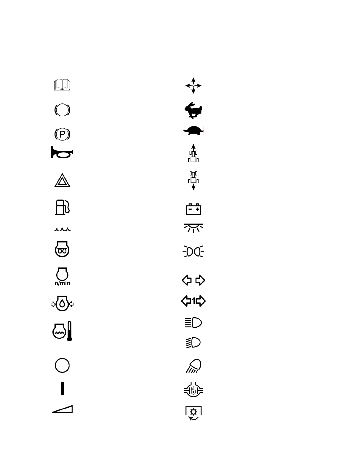
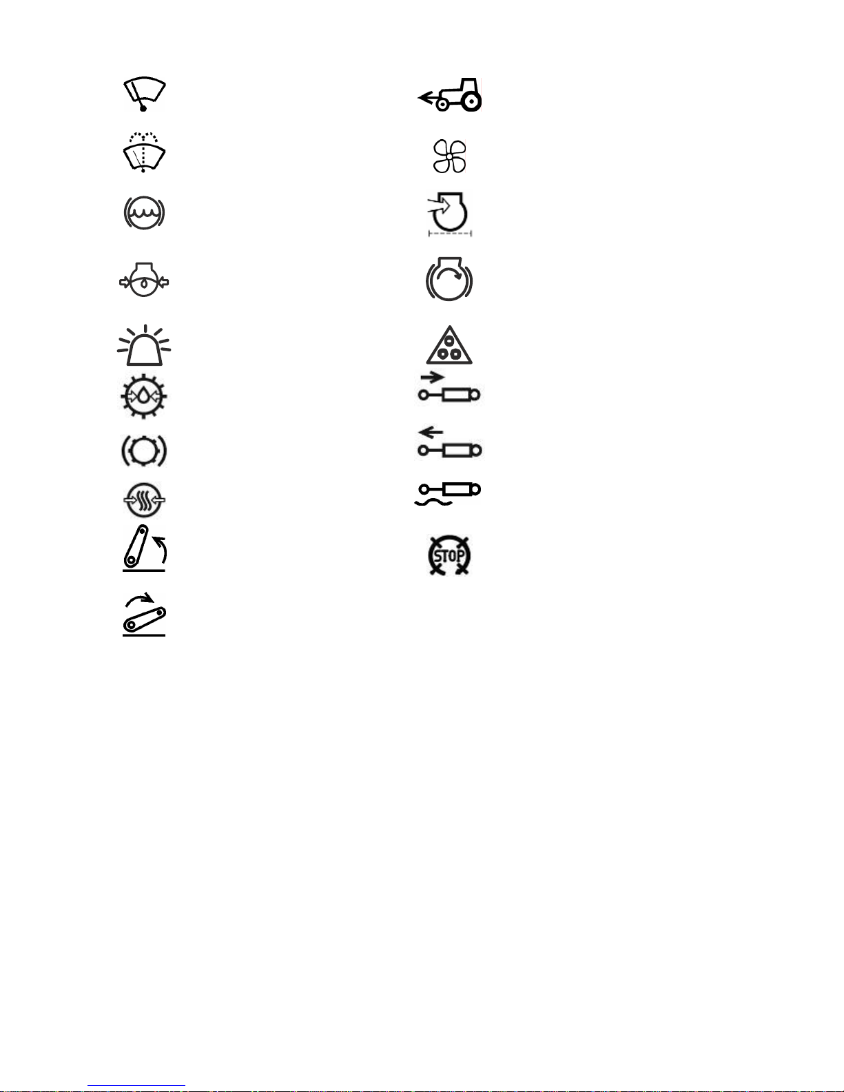
The manufacturer uses standard international symbols, regarding application of instruments and control units.
Given below are the symbols with indication of their meanings.
— see the manual ;
— control manipulations;
— brake;
— fast;
— manual brake;
— slowly;
— audible beep;
— forward;
— alarm signaling;
— reverse;
— fuel;
— accumulator charging;
— coolant;
— cab roof light;
— heating plugs;
— parking lights;
— engine speed;
— tractor turn indicator;
— oil pressure in the engine;
— trailer turn indicator;
— upper beam;
— temperature of engine cool-
ant;
— low beam;
— off / stop;
— working lights;
— on / start;
— differential lock;
— gradual adjustment;
— PTO engaged;
Page 10
952.5-0000010 OM
10
— front screen wiper;
— front driving axle drive;
— rear screen wiper and washer;
— fan;
— brake fluid level in main cylin-
der tanks;
— air filter clogged;
— oil pressure in HSC
— engine start;
— beacon
— road-train
— oil pressure in gearbox
— external cylinder – retracting
— braking of gearbox
— external cylinder – protracting
— air pressure in pneumatic system
— external cylinder – floating
— swivel lever – up
— engine stop
— swivel lever – down
Page 11
952.5-0000010 OM
11
1 TRACTOR DESCRIPTION AND OPERATION
1.1 Tractor assignment
The tractor “BELARUS-952.5” is intended for performance of various general –
purpose agricultural operations with mounted, semi-mounted and trailed machines and
implements, for loading-unloading works and transportation works.
The tractor “BELARUS-952.5” is a general-purpose wheeled tractor of traction class
1,4 with the wheel formula 4X4.
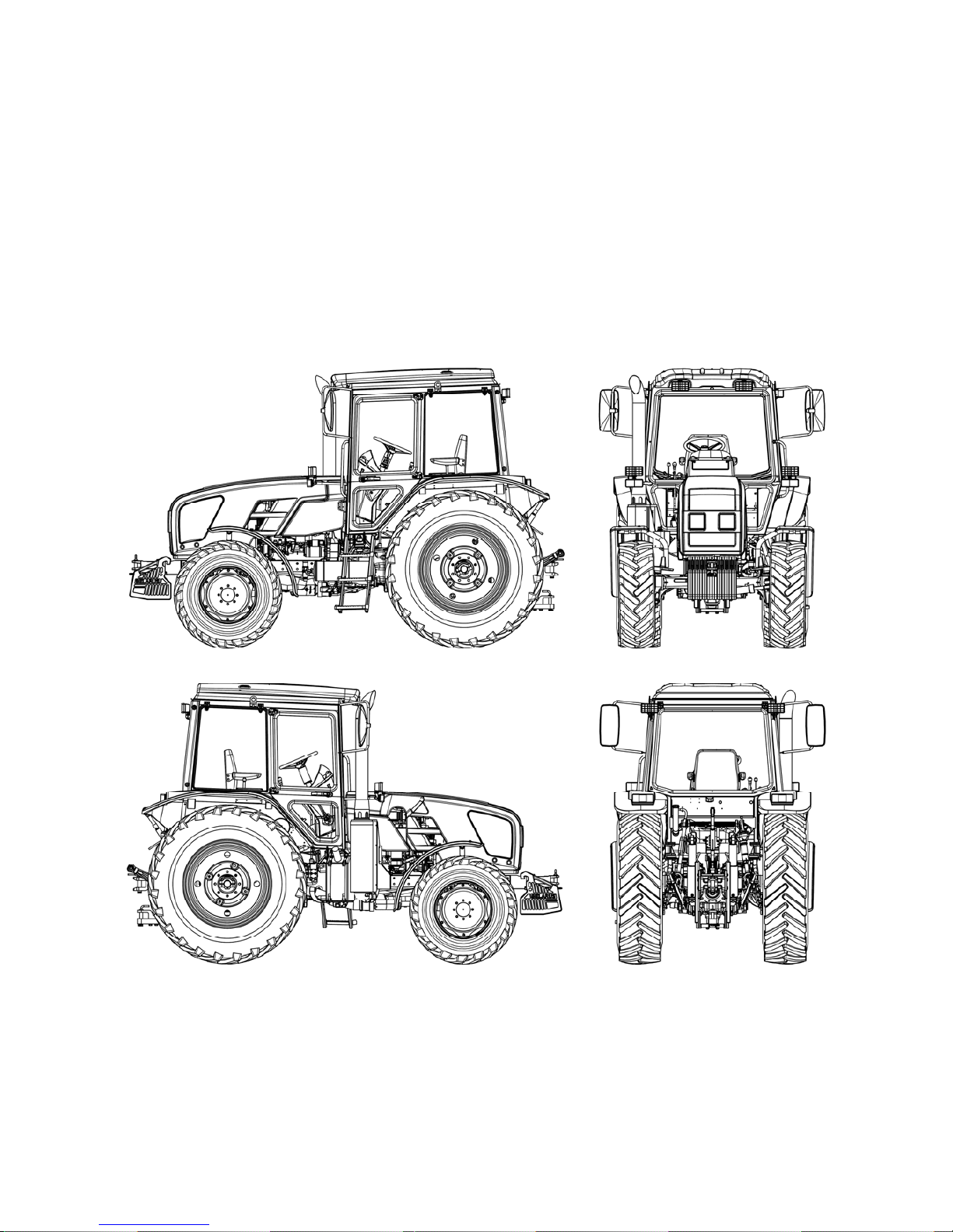
Appearance of the tractor “BELARUS-952.5” is presented in figures 1.1.1.
Figure 1.1.1 – Basic configuration of tractor “BELARUS-952.5”
Page 12

952.5-0000010 OM
12
1.2 Technical specifications
Main parameters and technical specifications of tractor BELARUS-952.5 are given in
table 1.1.
Table 1.1.
Parameter
(characteristics) title
Parameter value for the tractor
“BELARUS-952.5”
1 Traction class as per GOST 27021
1,4
2 Rated traction force, kN
14
3 Engine
1)
а) model
D-245.5S3В
b) engine type
2)
turbocharged with intercooling of the
charged air
c) number and position of cylinders 2) four, in-line, vertical
d) displacement, l 2)
4,75
e) engine power, kW:
1) rated 2)
70,0±2,0
2) normal
67,4±2,0
f) crankshaft rated speed, rpm 2)
1800
g) specific fuel consumption at normal
power, g/(kW·h)
2)
(223+7)
h) turning torque rated factor, % 2)
25
i) max turning torque, N·m 2)
464±18
4 Number of gears:
а) for forward travel
14 3)
b) for reverse travel
4
3)
5 Tractor travel speed (design) at crankshaft rated speed, and with tires 18.4R34
km/h:
а) for forward motion:
1) least
2,7
3)
2) highest
38,1
b) for backward motion:
1) least
5,6 3)
2) highest
12,6
6 Tractor weight, kg:
а) structural
4405±100
b) operating with ballast
5095±100
c) operating without ballast
4655±100
d) max. operating
7000
e) ex-works 4)
4505
7 Distribution of operating weight on axles, kg:
а) on front 2310±40
5)
(1730±40
6)
)
b) on rear 2785±60
5)
(2925±40
6)
)
Page 13

952.5-0000010 OM
13
Table 1.1 continued
Parameter
(characteristics) title
Parameter value for the tractor
“BELARUS-952.5”
8 Permitted load on axles, kN:
а) on front 37
b) on rear 53
9 Max weight of the trailer, kg
а) without brakes 2100
b) with independent brake 3500
c) with overrunning brake 3500
d) equipped with a brake system (trailer
brakes are interconnected with tractor
brakes)
18000
10 Agrotechnical clearance, mm (under
the axle tubes of rear wheels and on tyres
of basic configuration) not less than:
510
11 Track dimensions (on tyres of basic
configuration), mm:
а) on front wheels for short beam
FDA 822-2300020-02/04
1415±20, 1515±20, 1585±20, 1685±20,
1735±20, 1835±20, 1900±20, 2000±20
b) on front wheels for long beam
FDA 822-2300020-02/04
1535±20, 1635±20, 1705±20, 1805±20,
1855±20, 1955±20, 2020±20, 2120 ±20
c) for rear wheels
from 1500±20 to 1600±20 and from 1800±20 to 2100 ±20
d) for front wheels with mounted
FDA 72-2300020-А-04
1420±20, 1530±20, 1640±20,
1720±20, 1830±20, 1940±20
12 Least radius of turning circle (with
braking), m
4,5
13 Tractor base, mm 2450±20
14 Maximum fordable depth, m 0,85
15 Service life, years 12
16 Overall dimensions, mm:
а) length with weights and rear lift linkage
in transport position
4440±50
b) length over external diameters of
wheels
3850±50
c) width on rear wheel axle shaft ends
1970±20
d) height to the top of cab 2850±30
17 Tyres (basic configuration):
а) front wheels 360/70R24
b) rear wheels 18.4R34
18 Electrical equipment as per GOST
3940:
а) rated supply voltage in on-board
power system, V
12
b) rated ignition voltage, V 12
Page 14

952.5-0000010 OM
14
Table 1.1 finished
Parameter
(characteristics) title
Parameter value for the tractor
“BELARUS-952.5”
19 Hydraulic system:
а) pump displacement under crankshaft
rated speed, l/min, not less than
46
b) safety valve operation pressure, MPa
20-2
c) conventional volume factor, not less
than
0,65
20 Working equipment:
а) rear power take-off shaft:
1) rated speed of PTO shaft end with
the ground-speed drive on, rpm:
- position I (under the engine crankshaft
speed of 1632 rpm)
540 (596 7))
- position II (under the engine crankshaft
speed of 1673 rpm)
1000 (1076 7))
2) rated speed of PTO shaft end with
the continuous drive on, rev/meter of
travel:
3,36
(on rear tires of standard configuration
(18.4R34))
b) rear lift linkage:
1) loading capacity of rear lift linkage on
suspension axis on tractors with hydraulic lift,
kg, not less than
4200
2) loading capacity of rear lift linkage on
suspension axis on tractors with draft control
unit, kg, not less than
3000
3) time for raising rear lift linkage from
lowermost position into uppermost position
with test load on suspension axis, sec., not
more than
3
c) drawbar hitch: In section 4 “Coupling of implements”
__________________________________ ________________________________________________ ___________________________
1)
Engine parameters, not specified in the table 1.1, shall meet 245 S3В – 0000100
OM document.
2)
For referential use.
3)
Without a creeper. Installation of a creeper against order provides additional sixteen forward travel speeds and sixteen reverse travel speeds (on tractors with speed
increase unit).
4)
Specified depending on the configuration.
5)
With ballast weights mounted.
6)
Without ballast weights.
7)
At 1800 rpm of engine crankshaft speed
-1)
..
Note – Number of gears and travel speeds of the tractor at crankshaft rated speed
are given in table 1.1 for tractor “BELARUS-952.5” with speed increase unit mounted in
tractor transmission (basic configuration). Number of gears and travel speed of the tractor
“BELARUS-952.5 with reverse gear unit (optional configuration) are given in clauses
2.14.4 and 2.14.5 of the subsection 2.14 “Gear shifting”.
Page 15

952.5-0000010 OM
15
1.3 Tractor composition
Tractor framework – semi-frame.
Undercarriage: front and rear driving wheels, with pneumatic tyres of low pressure.
Steering wheels are front wheels. The wheels can be twinned by means of spacers.
The tractor is equipped with 4-stroke piston four-cylinder inner combustion engine
with in-line vertical arrangement of cylinders, with direct injection of diesel fuel and compression ignition, corresponding to environmental requirements of Stage 3B.
System of engine lubrication is combined, some parts are lubricated under pressure, some – by spattering. The lubrication system consists of an oil sump, oil pump, liquid-oil heat exchanger, oil filter and oil filter with paper filtering element.
The engine fuel supply system consists of the following parts:
- accumulator system of fuel supply Common RAIL, including a high-pressure fuel
pump, injectors, fuel accumulator under high pressure, sensors of engine working environment condition (pressure and temperature of fuel and air), electromagnetic actuating
mechanisms (fuel governor, electromagnetic injection valves), electronic unit of control and
communication check circuits, low-pressure pipelines, high-pressure pipelines;
- fuel fine filters;
- fuel coarse filters.
System of engine start-up is electric starter. A means of start-up facilitation under
low environmental temperatures are the heating plugs.
System of air delivery consists of a turbocharger, an air pipeline and a system of
charged air cooling.
The turbocharger is executed as follows: radial centripetal turbine and centrifugal
single-stage compressor with cantilever arrangement of wheels in relation to supports.
The system of air purification consists of a dry-type air cleaner of “Donaldson” com-
pany with two paper filtering elements. This air cleaner has two stages of purification.
Cooling system for charged air is of a radiator type. The CAC radiator is intended for
cooling the air, charged into the inlet collector.
System of engine cooling is closed-type with coolant compulsory circulation executed by a centrifugal pump. The water pump is driven by a V-belt from the crankshaft pulley. For acceleration of engine warming up after start-up and for automatic control of a
temperature mode at various loadings and ambient temperatures there is an thermostat.
To provide for a required chemical composition of exhaust gases under Tier-IIIB
stage the system of selective catalytic reduction (SCR) is additionally installed in the exhaust system.
The coupling clutch is frictional, dry, single-disk, spring-loaded. The CC overlays are
asbestos free. The coupling control drive is mechanical.
The gearbox is synchromesh with double-lever or single-lever control, with
synchronized speed increase unit, 14F + 4R
Option – synchromesh GB with double-lever or single lever control with
synchronized reverse gear unit, GB 7F+6R.
The rear axle is with the main drive, differential and final drives.
Brakes: service brakes are multidisk, oil-lubricated, located on final drive pinion
shafts; the parking brake is independent, manually controlled. It is possible to mount the
dry-friction brakes. The trailer brake control drive can be either double-line pneumatic, or
hydraulic, interlocked with tractor service brakes control. Against order the tractor may not
be equipped with the trailer brake pneumatic drive – tires are inflated through a valve of
the pneumatic compressor.
Page 16

952.5-0000010 OM
16
The rear power takeoff shaft is continuous dual-speed (540 and 1000 min-1) and synchronous, the direction of rotation is clockwise when viewed from the shaft end face. There are
PTO shaft end extensions: PTO shaft end extension 1 (6 splines, 540 min-1), PTO shaft
end extension 1c (8 splines, 540 min-1), PTO shaft end extension 2 (21 splines, 1000 min-
1).
Steering is hydrostatic. The feed pump is gear-type, the direction of rotation is left. The
dosing pump is gerotor-type. The type of the rotation mechanism - one hydraulic cylinder
(TS63x200) of bidirectional operation and a steering linkage.
The front driving axle – with main gear, a self-locked differential, final gears (planetary
gear groups). The FDA drive is a transfer gearbox with automatic FDA engagement, two
cardan shafts and intermediate bearing with overload clutch. The FDA drive control is mechanical.
The hydraulic system is remote cylinder hydraulic system with hydraulic lift (which provides
draft control, position control, depth and mixed control of the agricultural implements), or
with draft control unit (which provides draft, position and depth control of agricultural implements), with left and right side outputs. Optional can be mounted rear right outputs, interconnected with left side outputs. For operation with constant supply hydraulic units, for
example hydraulic engines, optional on the rear can be mounted free drain.
The rear lift linkage is a three-point linkage of category 2 under ISO 730 and a linkage 2
under GOST 10677 with outer or inner lock of lower links. There are two cylinders
TS80x220.
On tractors with hydraulic lift are mounted two cylinders TS80x220.
On tractors with draft control unit is mounted one cylinder TS100x200 (optional can be installed cylinder TS110x200).
Drawbar hitches on tractors equipped with hydraulic lift:
- short towing yoke DH 2V – for coupling with semi-trailers and semi-trailed imple-
ments;
- long towing yoke DH 3V – for coupling with trailers and trailed implements;
- pin DH-2R (“Pithon”) – for coupling with semi-trailers and semi-trailed machines
(option);
- towing bar DH-1M-01 –for coupling with semi-trailed and trailed agricultural ma-
chines (option);
- crossbar DH-1 – for coupling with trailed and semi-trailed machines (option).
- twin cross member DH-1ZH-01 – for coupling with trailed and semi-trailed ma-
chines (against order).
Drawbar hitches on tractors equipped with rear lift linkage with draft control unit:
- hydraulic hook DH-2 – for coupling with semitrailers and semitrailed agricultural
machines;
- floating drawbar DH-1M for coupling with semitrailed and trailed agricultural ma-
chines (optional);
- combined drawbar DH-1M-02 (with variable functions of DH-2 and DH-1M) – for
coupling with semitrailed and trailed agricultural machines; with semitrailers and semitrailed agricultural machines depending on mounted coupling element (optional);
-lowering link – for coupling with semitrailed and trailed agricultural machines
(optional);
- crossbar DH-1ZH – for coupling with trailed and semitrailed machines (optional);
- twin crossbar DH-1ZH-01 for coupling with trailed and semi-trailed machines
(option).
Page 17

952.5-0000010 OM
17
The cabin is a one-seated with a protective rigid framework, having thermal, noise
and vibration insulation, equipped with a sprung seat adjustable for operator's height and
weight, with rear-view mirrors, with a sun visor, with electrical wipers for front and rear
screens, with front and rear screen washers, with a roof lamp and a place to install a radio
set, with a system of heating and ventilation (upon request – additional air-conditioning).
Upon request the tractor can be equipped with an additional seat. The cab doors have got
locks, there are keys for the left door. Right door is for emergency exit. The cab complies
with category 2 under EN 15695-1:2009.
The electrical equipment complies with GOST 3940. The rated power supply voltage for on-board network is 12V. The rated voltage for the start-up is 12V.
Instruments are a combination of devices; these are an integrated indicator; informational display; pilot lamps (glow lamps and light emitting diodes), located on the block of
pilot lamps, on the control panel of the rear axle differential lock and rear PTO, on the engine control system board.
Page 18
952.5-0000010 OM
18
1.4 Vibration level at the operator's working place of the tractor “BELARUS-952.5”
The vibration level at the operator's seat complies with the Council Directive
78/764/ЕEС. Values for the vibration level are given in the EU type approval on each type
of a seat.
1.5 Noise level at the operator's working place of the tractor “BELARUS-952.5”
Noise level at the operator's workplace conforms to Directive 2009/76/ЕС, Appendix
2, and does not exceed the value 86 dB (A). External noise level conforms to Directive
2009/63/ЕС and does not exceed the value 89 dB (A).
1.6 Tractor and its component marking
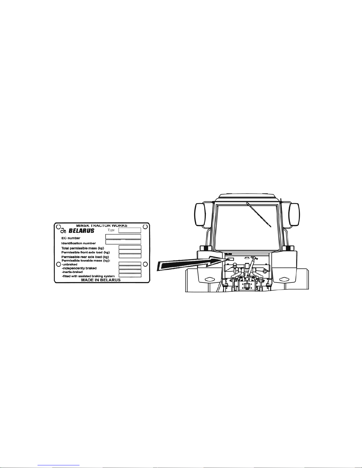
Metal nameplate is fixed at the rear of the cab on the left side, as shown in fig.
1.6.1.
Additionally the tractor serial number is applied by means of percussion on the right
side member and duplicated on the right plate of the front ballast weight.
Figure 1.6.1 – Place of application the tractor nameplate
Engine number and numbers of its components are given in engine operation manual.
Numbers of tractor components are given in table 1.2
Page 19
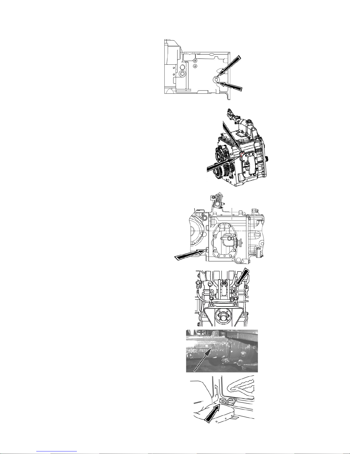
952.5-0000010 OM
19
Table 1.2 – Numbers of tractor components
Number of clutch casing
(to the left along the tractor
movement)
Number of gear box
(to the left along the tractor
movement)
Transmission and rear axle
serial number on tractors with
hydraulic lift (to the right along
the tractor movement)
Transmission and rear axle
serial number on tractors with
draft control unit (on rear axle
body from behind)
FDA number
Cab serial number
Serial number
Clutch case
configuration
number
Serial number
Clutch
configuration
number
Clutch case
GB
RA
Page 20
952.5-0000010 OM
20
2 CONTROLS AND INSTRUMENTS
2.1 Layout of controls and instruments of the tractor
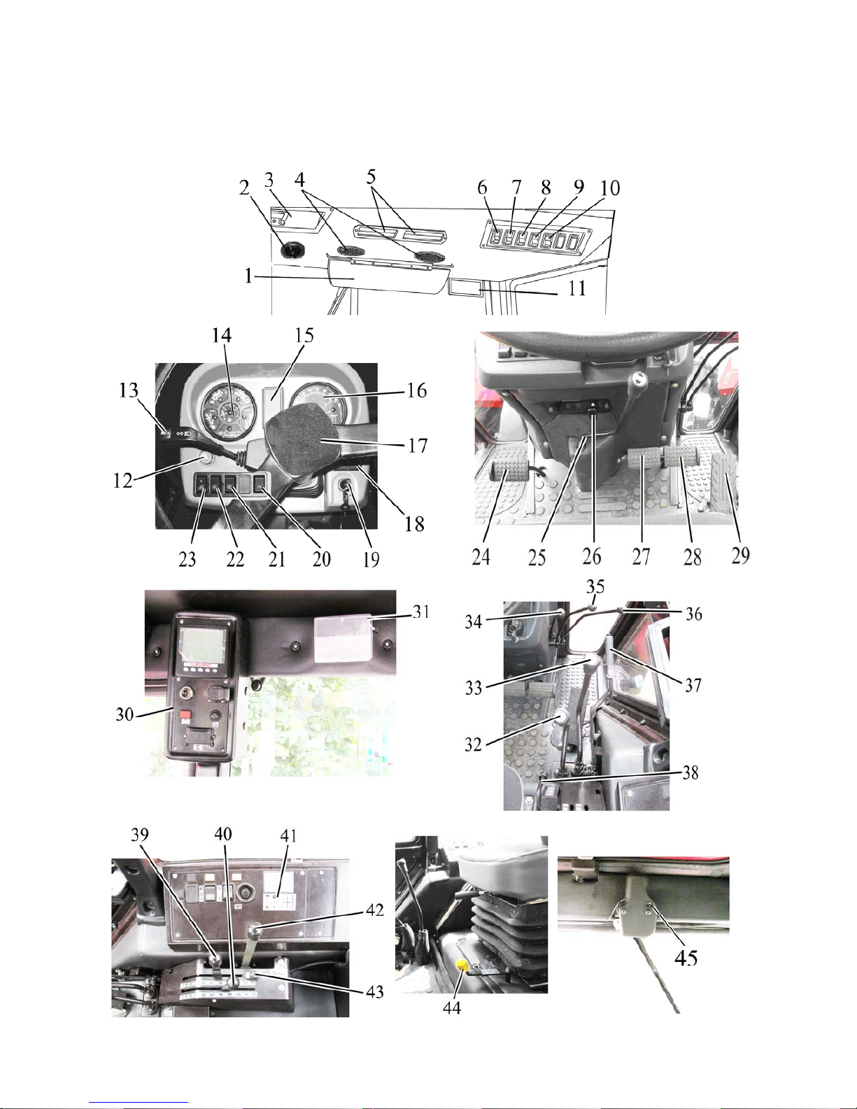
Controls and instruments, located in the tractor cab, are presented in fig. 2.1.1.
Figure 2.1.1 – Tractor controls and instruments
Page 21
952.5-0000010 OM
21
To the figure 2.1.1 – Layout of controls and instruments of the tractor:
1 – sun visor; 2 – handle to control the cab heater valve; 3 – place for radio receiver (car
stereo) installation; 4 – deflectors; 5 –recirculation shutters; 6 – windscreen wiper switch; 7 – cab
heater fan switch; 8 – rear lights switch; 9 – switch of front lights on the cab roof; 10 – „Road-train“
light switch (design variant); 11 – rear view mirror; 12 – emergency flashing switch; 13 – multifunctional underwheel switch; 14 – instrument board; 15 – pilot lamps unit; 16 – integrated indicator; 17
– steering wheel; 18 – integrated indicator control panel; 19 – starter and instruments switch; 20 –
accumulator battery remote disconnect switch; 21 – windscreen washer switch; 22 – central light
switch; 23 – switch of front lights mounted on handgrips switch; 24 – clutch control pedal; 25 –
control lever of speed increase unit; 26 – handle for steering rake tilt fixation; 27 – left brake control pedal; 28 – right brake control pedal; 29 – accelerator pedal; 30 – engine control board; 31 –
cab lamp with switch; 32 – range shifting lever of gearbox; 33 – gear shifting lever of gearbox;
34,35,36 – levers to control hydrosystem outlets; 37 – parking brake control lever; 38 – FDA drive
control lever; 39, 40 – RLL hydrohoist control levers; 41 – console to control rear axle DL and rear
PTO; 42 – handle to control fuel supply.. 43 – limiter for the position control lever; 44 – handle to
switch between the ground-speed and continuous drives of PTO; 45 – rear screen wiper switch;
Instead of electrohydraulic control of rear axle DL and rear PTO, control system of rear
lift linkage with hydraulic lift your tractor can be optional equipped with mechanical control of
rear axle DL and rear PTO, with control system of RLL with draft control unit.
Also your tractor can be additional equipped with the following:
- instead of fan-heater an air-conditioner can be mouted;
- instead of double-lever GB control an single-lever GB control can be mounted;
- instead of speed increase unit an reverse gear unit can be mounted;
- instead of HLL outputs control with a help of levers optional can be mounted HLL
outputs control with joystick and lever;
- creeper installation is possible.
2.2 Switches of instrument board
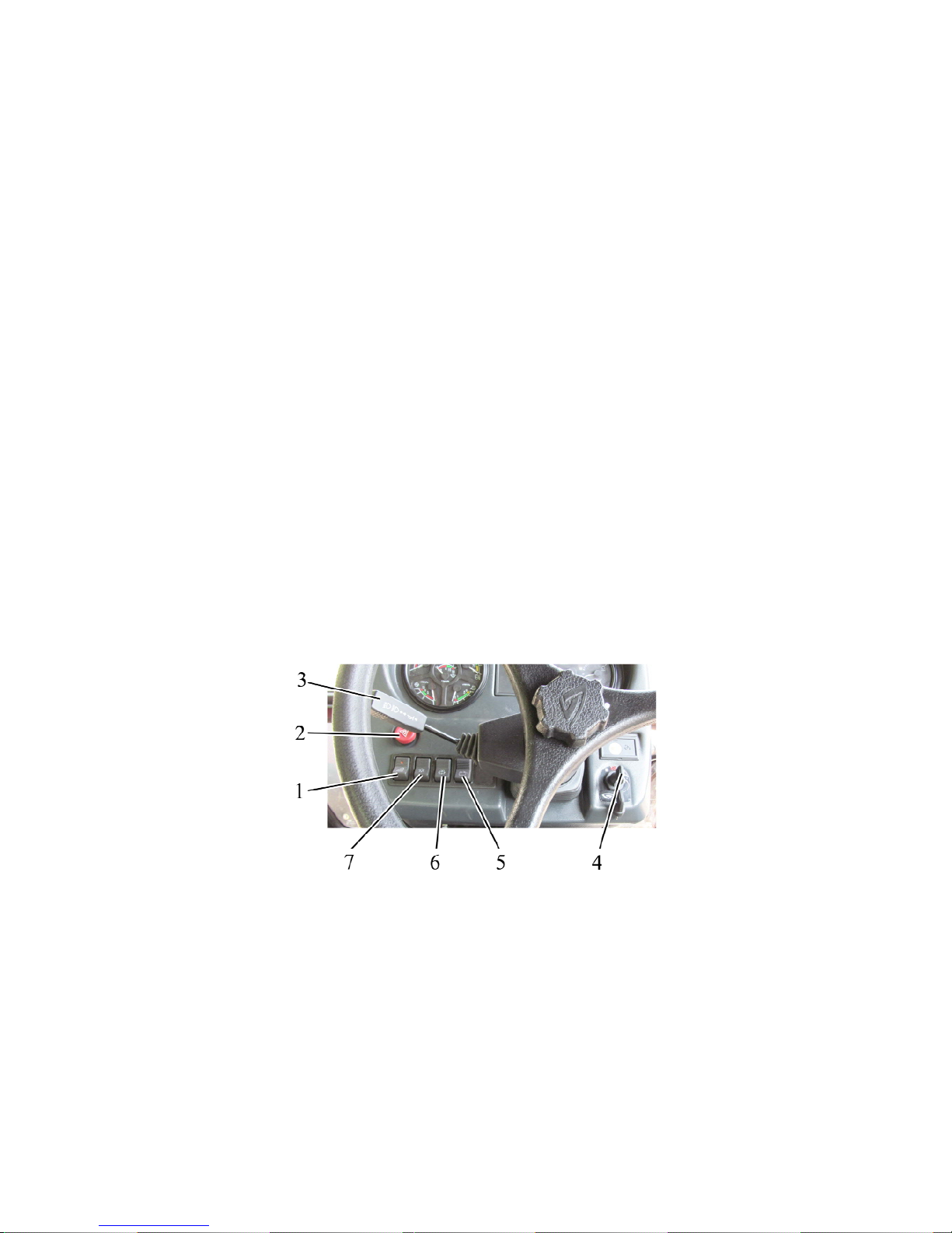
1 – switch of front working lights, mounted on handgrips; 2 – emergency flashing
switch; 3 – multifunctional underwheel switch; 4 – starter and instruments switch; 5 – accumulator battery remote switch; 6 – windscreen washer switch; 7 – central light switch.
Figure 2.2.1 – Switches of instrument board
The starter and instruments switch 4 (see fig. 2.2.1) has four positions:
- «0» – off;
- «I» – instruments; pilot lamps unit, heating plugs are on;
- «II» – starter is on (non-fixed position);
- «III» – radio set is on.
Page 22

952.5-0000010 OM
22
The layout of positions of starter and instruments disconnect switch is given in fig.
2.2.2 and in informational plate of the switch.
Figure 2.2.2 – Layout of positions of starter and instruments disconnect switch
ATTENTION: THE REPEATED SWITCH-ON OF THE STARTER IS POSSIBLE
ONLY AFTER RETURN OF THE KEY INTO POSITION “0” OF THE SWITCH. TO TURN
THE STARTER AND INSTRUMENTS SWITCH INTO POSITION “III” IT IS NECESSARY
TO PRESS IN THE KEY WHEN IN “0” POSITION AND TURN IT CONTRACLOCKWISE!
The multifunctional underwheel switch 3 (fig 2.2.1) provides for activation of turn
blinkers, switching between upper and lower beam of headlights, upper beam blinking, audible beep:
- as you move the lever of the underwheel switch 3 from or to yourself the right and
the left flashers are turned on accordingly. As the tractor has made a turn the lever automatically returns to the initial position.
- the audible beep is activated by pressing the lever in axial direction. The beep can be
activated in any position of the underwheel switch 3.
- as the road headlights are turned on (the button 7 is set to position “III”) and the
lever of the underwheel switch 3 is moved down, the upper beam gets activated, and as
the road headlights are on and the lever of the underwheel switch is moved up – the lower
beam gets activated.
- as you move the lever of the switch 3 from the lower beam position up against the
stop, the upper beam turns on for a short time (“upper beam blinking, non-fixed position) irrespective of irrespective of the position of the central light switch. As you release the lever it
will automatically return to the lower beam position.
Pressing the emergency flashing button 2 (fig. 2.2.1) activates the emergency flashing. A pilot lamp, built in the button, flashes simultaneously with the emergency flashing
lights. Repeated pressing the button 2 deactivates the emergency flashing.
The central light switch 7 (fig.2.2.1) has three positions:
- position “I” – “off” (the upper part of the button is pressed as in fig 2.2.1);
- position ”II” – “front and rear parking lights, license plate lights, lighting of instruments on
the dashboard and also parking lights on a trailed machine are on” (middle position);
- position “III” – “all consumers of “II” position and road headlights are on” (lower part of
the button is pressed against the stop as in fig. 2.2.1).
When pressing the button of front working lights switch 1 (fig. 2.2.1) two front working lights, located on light brackets, are actuated together with a light indicator, built in the
button.
Pressing the button 6 ((Figure 2.2.1) (non-fixed position) turns the windscreen
washer on. Releasing the button 6 turns the windscreen washer off.
Pressing the button (non-fixed position) of the accumulator battery remote disconnect switch 5 (fig. 2.2.1) the accumulator batteries are powered, the repeated pressing deactivates the accumulator batteries.
Page 23
952.5-0000010 OM
23
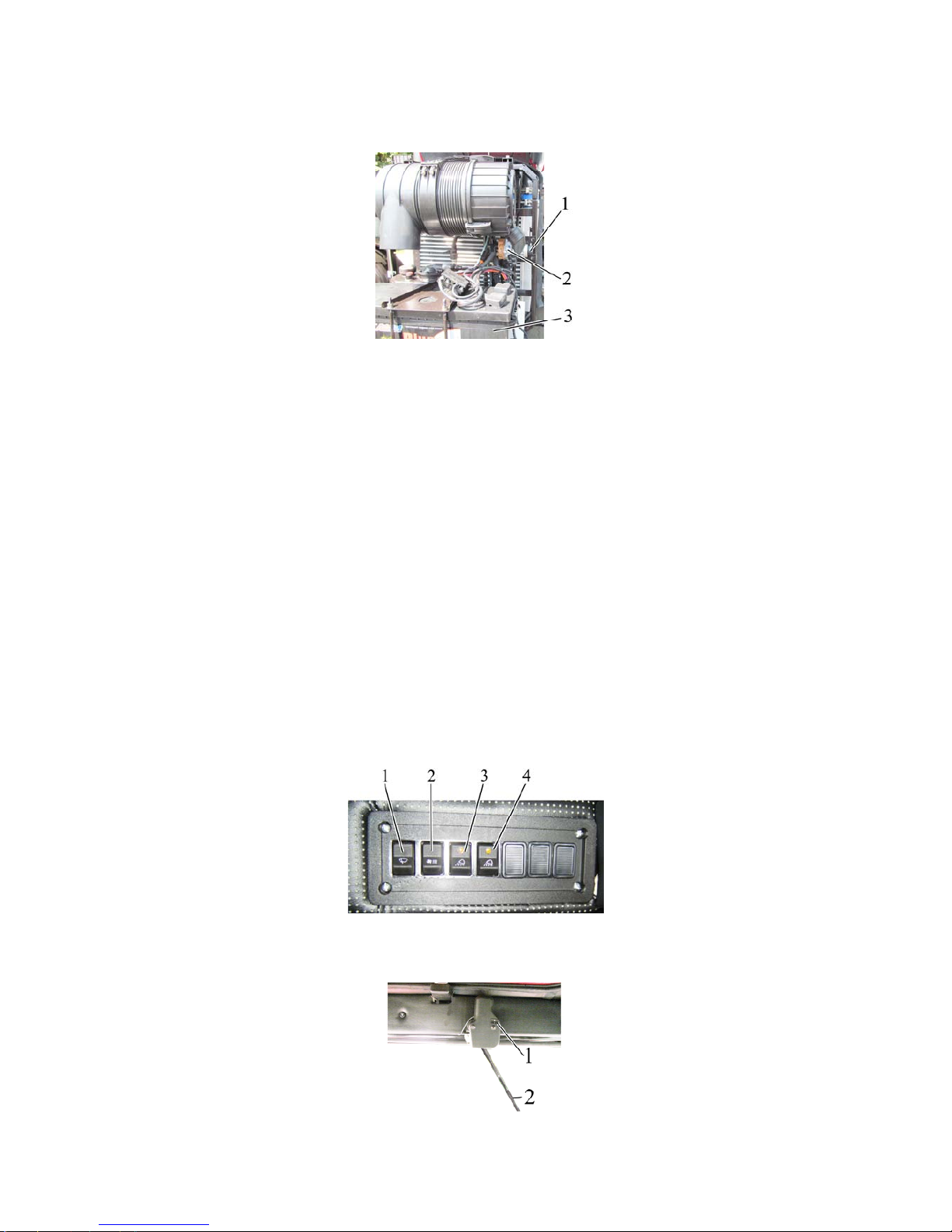
It is possible to activate and deactivate the accumulator battery by means of the accumulator battery manual switch 2 (figure 2.2.3) located in the area of the accumulator battery installation. To activate and deactivate the accumulator battery it is necessary to press
the button 1.
1 – button; 2 – AB manual disconnect switch; 3 – accumulator battery.
Figure 2.2.3 – Installation of the accumulator battery manual disconnect switch
2.3 Upper shield unit of button switches and rear wiper switch
Pressing the switch button 1 ((Figure 2.3.1) turns on the windscreen wiper.
The switch has got three positions:
“Off”;
“On with low speed”;
“On with high speed”.
Pressing the switch button 2 (Figure 2.3.1) turns on air ventilation in the cab.
The switch has three positions:
“Off”;
“On in the mode of low feed of air”;
“On in the mode of large feed of air”.
More detailed information on controlling the heater fan is given below.
Pressing the switch button 3 (Figure 2.3.1) turns two rear working lights on as well
as the light indicator, built into the button.
Pressing the switch button 4 (Figure 2.3.1) turns two front working lights on the cab
roof on as well as the light indicator, built into the button.
1 – windscreen wiper switch; 2 – cab heater switch; 3 – rear working lights switch; 4 – switch of front
working lights on cab roof.
Figure 2.3.1 – Upper shield unit of button switches
The rear window wiper is turned on and off with a switch 1 (Figure 2.3.2).
1 – switch; 2 – rear window wiper arm.
Figure 2.3.2 – Activation and deactivation of rear window wiper
Page 24
952.5-0000010 OM
24
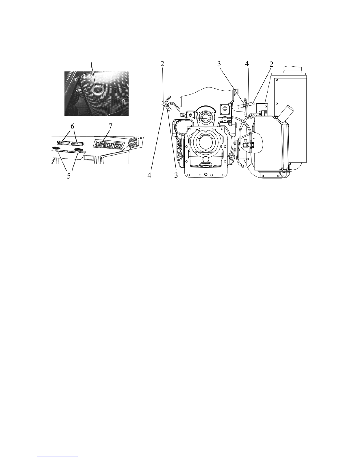
2.4 Cab heater and fan control
Cab heater and fan controls are shown in Figure 2.4.1.
1 - heater valve handle; 2- cab heater hose; 3- T-piece; 4- clamp;
5-deflector; 6 - recirculating screen; 7- cab fan switch.
Figure 2.4.1 – Cab heater and fan controls
Cab heater and fan can operate in two modes: heating and ventilation.
In order to actuate heater and fan in heating mode it is necessary to perform the follow-
ing:
- after filling of cooling system start the engine and let it operate at medium rpm for
warming-up of water up to the temperature from + 500C to 700C, then open heater valve.
To do this turn the valve handle 1 (Fig. 2.4.1) counterclockwise up to the stop. Increase
engine rpm and in 1…2 minutes ensure that coolant is circulated through heating radiator.
The heating radiator should start warming-up. In course of this level of coolant in the engine cooling system should come down.
- refill coolant in the expansion chamber in half of the expansion chamber capacity.
- switch the heater fan on by means of switch 7 and direct the air flow by means of deflectors 5;
- the volume of air ventilated into the cab can be controlled by opening of recirculating
screens 6;
In order to drain coolant from heating system disconnect cab heater hoses 2 (are situated to the left and to the right of tractor cab) from T-pieces 3 by loosening the clamps 4
and drain cooling liquid into special reservoir. After coolant has been drained blow off the
system with compressed air. After blowing off connect cab heater hoses 2 with T-pieces 3
and tighten the clamps 4.
ATTENTION: WHEN HEATING AND VENTILATING SYSTEM IS OPERATED IN
HEATING MODE CAB VENTILATION IS PERFORMED SIMULTANEOUSLY. TO OPERATE
HEATING AND VENTILATING SYSTEM IN VENTILATING ONLY (DURING WARM SEASON) THE HEATER’S VALVE SHOULD BE CLOSED!
You tractor can be equipped with conditioning system instead of heating and ventilating
system. Guidelines on conditioner control are presented below.
Page 25
952.5-0000010 OM
25
2.5 Conditioner control
2.5.1 Conditioner control in conditioning mode
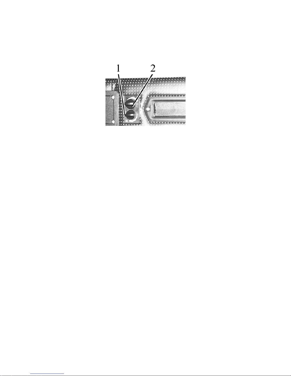
The conditioner control unit has switches 1 and 2 (figure 2.5.1).
1 – Switch for air flow adjustment;
2 – Conditioner cut-out switch and cooling capacity adjustment;
Figure 2.5.1 Conditioner control unit
With the help of the switch 1 you can change air flow by changing fan speed. The
switch 2 allows to change temperature of cold and dry air coming out from deflectors 4
(fig. 2.1.1) in the conditioning mode.
ATTENTION: THE AIR CONDITIONER CAN BE SWITCHED ON AND OPERATE
ONLY WITH THE ENGINE ON!
To switch on the conditioner it is required to do the following:
- turn the cut-out switch 2 (figure 2.5.1) clockwise by 180° until a blue scale be-
gins;
- then turn the switch 1 to one of three marked positions (the fan rotor has three
kinds of rotation speed). After 3-5 minutes adjust a required temperature in the
cab with the switch 2;
- it is possible to adjust a mixture of outer air and recirculation air with recirculation
shutters 5 (figure 2.1.1) located on the upper panel;
To switch off the conditioner it is required to turn both switches 1 and 2 (figure 2.5.1)
counterclockwise into “0” position.
ATTENTION: MAKE SURE THE CONDITIONER IS SWITCHED OFF BEFORE
STOPPING THE ENGINE!
ATTENTION: WHEN THE CONDITIONER OPERATES IN THE COOLING MODE
MAKE SURE THAT THE HEATER CONTROL VALVE IS SHUT OFF IN ORDER TO
PREVENT THE SYSTEMS OF HEATING AND COOLING FROM SIMULTANEOUS
OPERATION!
2.5.2 Conditioner control in a heating mode
ATTENTION: REFILLING THE ENGINE COOLING SYSTEM SHALL BE CARRIED
OUT ONLY WITH LOW-FREEZING LIQUID SPECIFIED IN SUBSECTION "REFILLING
AND LUBRICATION OF A TRACTOR WITH LUBRICANTS”!
Page 26
952.5-0000010 OM
26
To set the conditioner into the heating mode do the following:
- after refilling the cooling system with the cooling fluid start the engine and let the engine
run at medium idle without opening the heater control valve to reach 70-80°C of cooling
system temperature;
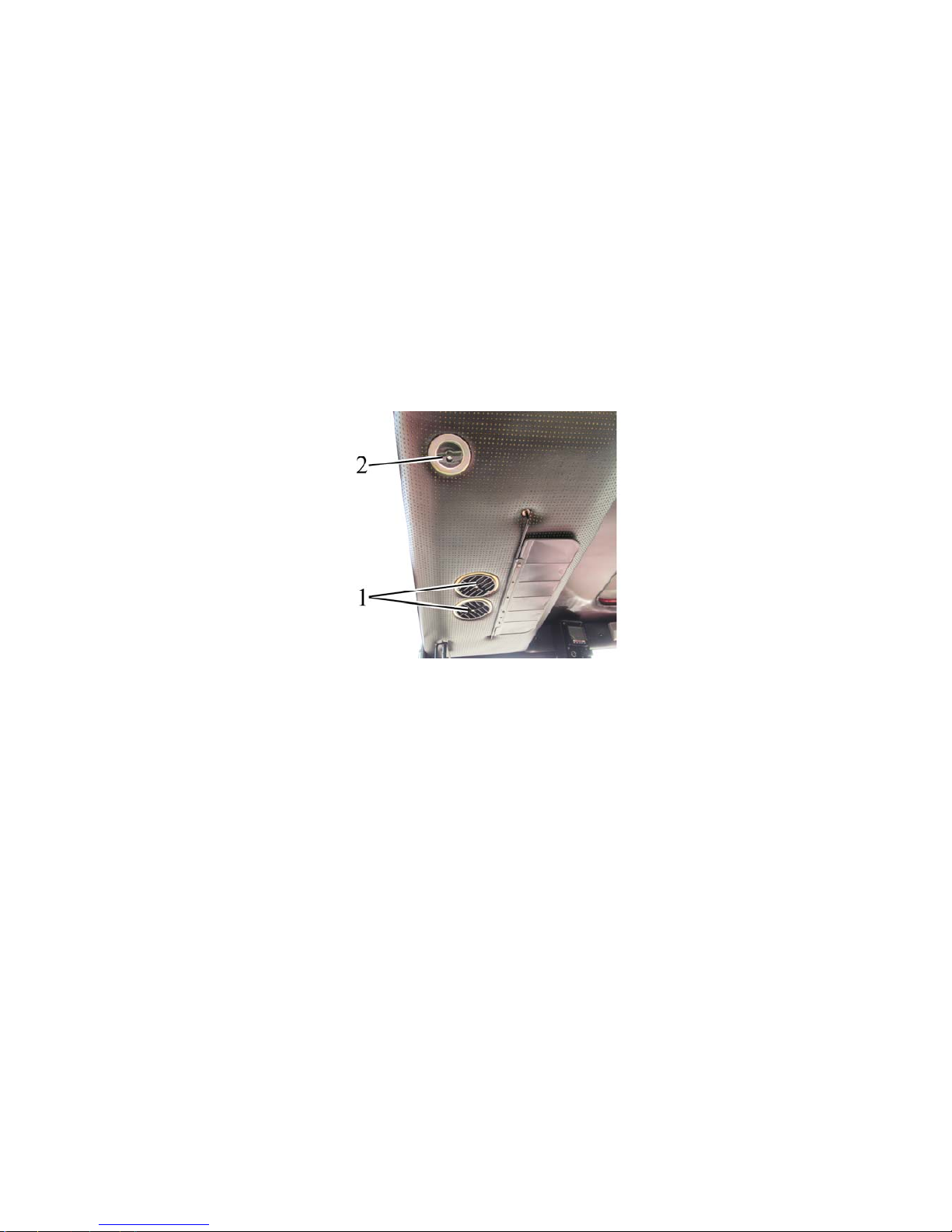
- then open the control valve with a handle 2 (figure 2.5.2), to do this turn the handle 2
counterclockwise against the stop;
- increase engine speed and let it run for one-two minutes until the heater radiator is filled
up with the fluid. Make sure the fluid circulates through the heater. The heater radiator
must warm up. Herewith the cooling fluid level in the cooling system radiator will decrease;
- refill the cooling fluid in expansion tank till the cooling fluid level in the expansion tank
reaches the half of the expansion tank;
- to warm up the cab quickly switch on the heater fan and open recirculation shutters;
ATTENTION: WHEN OPERATING IN THE HEATING MODE THE SWITCH 2 (FIGURE
2.5.1) SHALL BE COMPLETELY OFF TO PREVENT THE COOLING SYSTEM AND THE
HEATING SYSTEM FROM SIMULTANEOUS OPERATION!
1 – deflectors, 2 – handle of heater control valve
Figure 2.5.2 – Installation of heater control valve
Note – Rules of draining the cooling fluid from the air heating and conditioning system are
given in subsection 2.4 “Cab heater and fan control”.
2.5.3 Cab ventilation
During the conditioner operation in the cooling and heating modes the cab ventilation is executed simultaneously. To make the conditioner operate only in the ventilation
mode it is necessary to close the heater control valve, set the switch 2 (figure 2.5.1.) in position “0” and the switch 1 in any of three marked positions.
Page 27
952.5-0000010 OM
27
2.6 Instrument board
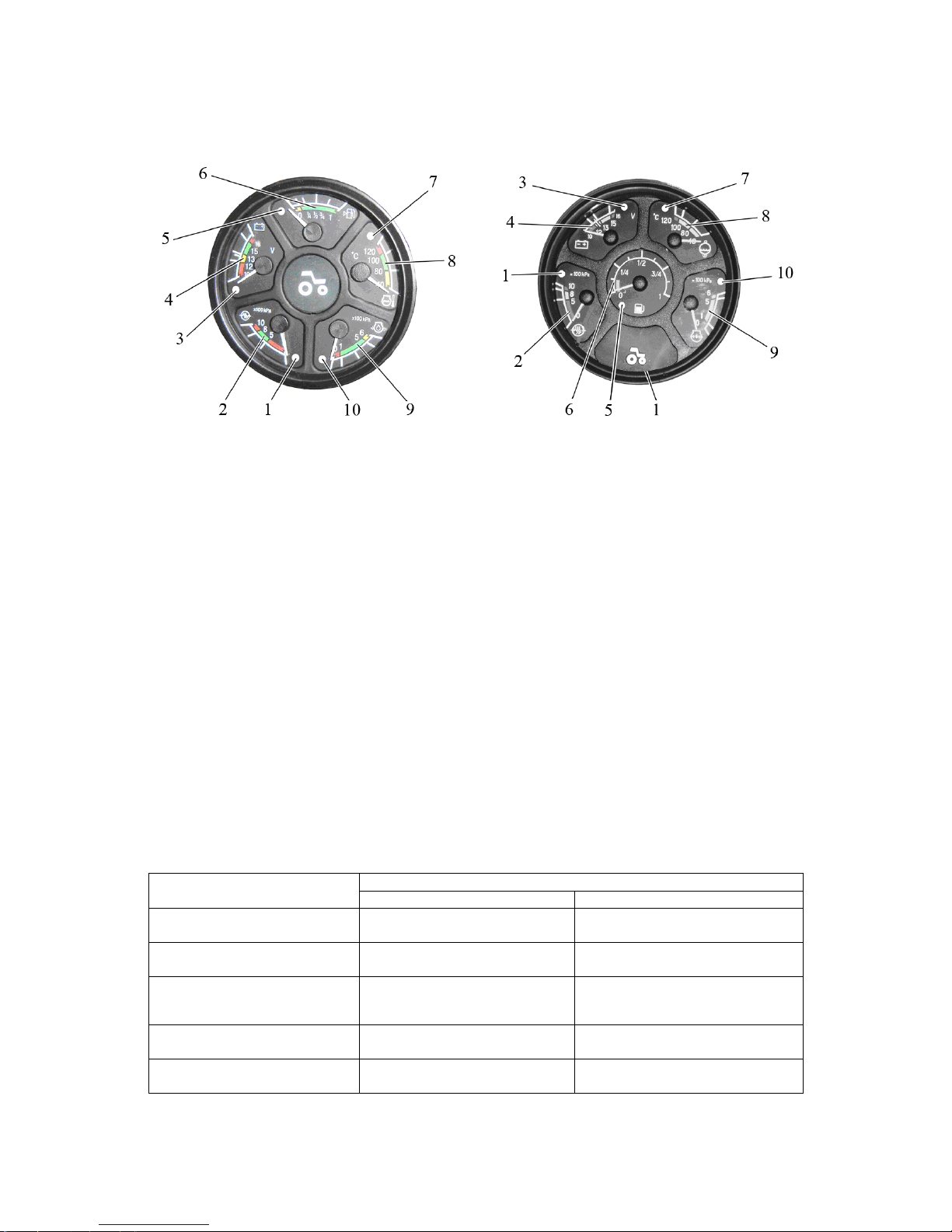
The instrument board 14 (figure 2.1.1) includes five gauges with five signal lamps
as shown in figure 2.6.1.
1 – signal lamp of emergency air pressure in the pneumatic system; 2 – gauge to
indicate air pressure in the pneumatic system; 3 – pilot lamp of additional accumulator battery (not used); 4 – voltage gauge; 5 – signal lamp of reserve fuel volume in the tank;
6 – gauge to indicate fuel volume in the tank; 7 – signal lamp of emergency temperature of
engine coolant; 8 – gauge to indicate temperature of engine coolant; 9 – gauge to indicate
oil pressure in the engine lubrication system; 10 – signal lamp of emergency oil pressure in
the engine lubrication system;
Figure 2.6.1 – Instrument board
2.6.1 The scale of the gauge of oil pressure in the pneumatic system 2 has three zones:
- working – from 500 to 800 kPa (green color);
- emergency (two) — from 0 to 500 kPa and from 800 to 1000 kPa (red color).
A signal lamp 1 (red color) is built in the gauge scale which lights up when the pressure in
the pneumatic system drops below 500 kPa.
2.6.2 The voltage gauge 4 (figure 2.6.1) indicates accumulator batteries voltage with the
engine stopped when the key of starter and instruments switch (figure 2.2.2) is set in position “I”. With the engine running the voltage gauge indicates voltage on generator terminals.
The states of the power supply system depending on the position of the
gauge pointer on the scale are given in table 2.1.
Table 2.1 – The states of the power supply system
States of power supply system Zone on the voltage gauge
scale 4 (figure 2.5.1), color
with the engine running with the engine stopped
13,0 – 15,0 V
green
normal mode of charge –
10,0 – 12,0 V
red
the generator is out of order
accumulator battery
discharged
12,0 – 13,0 V
yellow
No AB charge
(low charging voltage)
AB has a normal charge
15,0 – 16,0 V
red
AB recharge –
white line in the yellow zone -
Rated AB electromotive force
is 12,7 V
ATTENTION: IF THE VOLTAGE GAUGE INDICATES ABSENCE OF AB CHARGE,
CHECK THE STATE AND TENSION OF THE GENERATOR DRIVE BELT!
Variant 1 Variant 2
Page 28
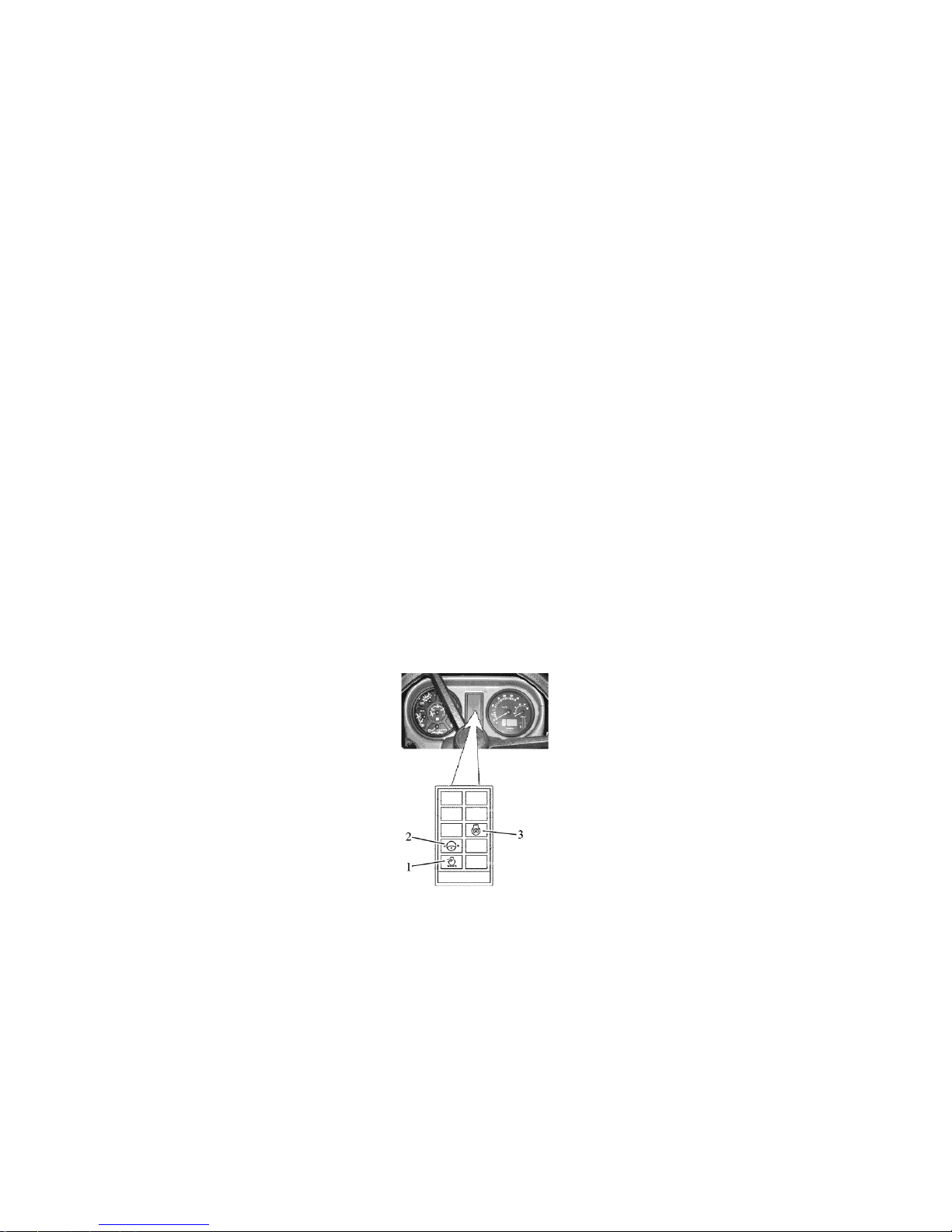
952.5-0000010 OM
28
2.6.3 The scale of the gauge indicating fuel volume in the tank 6 (figure 2.6.1) has the
divisions “0-1/4-1/2-3/4-1”. A signal lamp 5 (orange color) is built in the gauge scale, which
lights up when fuel volume in the tank drops below 1/8 of the total tank volume.
ATTENTION: DO NOT LET THE TANK BECOME EMPTY (THE GAUGE POINTER IS IN
THE ZONE OF ORANGE COLOR)!
2.6.4 The gauge scale of engine coolant temperature 8 has three zones:
- working – from 80 to 105 °С (green color);
- informational – from 40 to 80 °С (yellow color);
- emergency – from 105 to 120 °С (red color);
An emergency temperature lamp (red color) 7 is built in the scale, which operates in
two modes:
- lights up and operates in a flashing mode with coolant values from 109 up to and in-
cluding 112 °С.
- glows in a continuous mode with coolant temperature values from 113 °С and higher.
2.6.5 The oil pressure gauge scale in the engine lubricating system 9 has three zones:
- working – from 100 to 500 kPa (green color);
- emergency (two) – 0 to 100 kPa and from 500 to 600 kPa (red color).
A signal lamp of emergency oil pressure drop 10 (red color) is built in the gauge scale,
which lights up when the pressure drops below 100 kPa.
ATTENTION: WHEN THE COLD ENGINE IS STARTED THE PRESSURE CAN BE 600 kPa
and HIGHER!
ATTENTION: IF THE EMERGENCY PRESSURE LAMP IS ON WITH THE ENGINE RUNNING,
IMMEDIATELY STOP THE ENGINE AND ELIMINATE THE FAILURE!
2.7 Pilot lamps unit
2.7.1 General information
The pilot lamps unit 15 (figure 2.1.1) includes three lamps. The allocation scheme is
presented in figure 2. 7.1.
1 – pilot lamp to indicate that the air cleaner filter is clogged to the max. (orange color);
2 – pilot lamp to indicate emergency oil pressure drop in the system of hydrostatic power
steering (red color); 3 – pilot lamp to indicate operation of heating plugs (orange color)
Figure 2.7.1 – Pilot lamps unit
The operating principle of the pilot lamps of CLU is the following:
- pilot lamp 1 to indicate that the air filter is clogged to the max. (figure 2.7.1) lights up
when the max. permissible level of filter dirtiness is exceeded and the filter requires cleaning;
- pilot lamp 2 to indicate emergency oil pressure drop in the system of hydrostatic
power steering lights up when the oil pressure in the system of hydrostatic power steering
drops below 0,08 MPa (periodic lighting up of the lamp 2 with engine minimal speed is assumed – when revolutions are increased the lamp 2 shall go out);
- pilot lamp to indicate operation of heating plugs 3 indicates heating plugs operation
(functioning algorithm of the pilot lamp indicating heating plugs operation is provided below).
Page 29

952.5-0000010 OM
29
2.7.2 Functioning algorithm of pilot lamp to indicate operation of heating plugs
As a means of start facilitation heating plugs (HP) are used in tractors “BELARUS –
952.5”, they are mounted in the cylinder head. For individual control of heating plug opera-
tion modes, indication of their operation a heating plug control unit is used.
The heating plugs are activated, if the engine temperature exceeds +5°C. Hereby a
heating plug pilot lamp 3 (figure 2.7.1) lights up for 2 sec., or doesn’t light up at all.
If engine temperature is below +5°C, the heating plugs are activated automatically
as the key of starter and instrument switch is turned from position “0” (off) into position “I”
(Instruments on). Hereby the heating plug pilot lamp 3 lights up in the pilot lamp unit of the
dashboard. The heating plug operation time depends on engine temperature as per table
2.2. The engine is to be started as the lamp 3 goes out after the time, specified in table
2.2. After the engine start-up, the heating plugs remain on for some time, then they go out.
The heating plug operation time after the engine start-up depends on the engine temperature at the moment of the heating plug activation. (see table 2.2).
If during (10±1) sec. after the lamp 3 goes out the engine will not be started, heating plugs
become switched off.
The heating plug operation algorithm has the following emergency modes:
- as the key of starter and instrument switch is turned from position “0” (Off) into
position “I” (Instruments on) the heating plug pilot lamp starts to flash continuously with
2 Hz frequency. This means that there is a failure in the heating plug operation – all heating plugs are closed-circuit or their connection is disturbed (disconnected from the heating
plug control unit), the heating plug control unit is not powered or the power supply wire is
damaged. Herewith, in case of short circuit the heating plug control unit cuts power supply
(12V) to the heating plugs.
- after the engine start-up the heating plug pilot lamp 3 starts flashing for one minute
with 3 sec. of cycle duration and 0,25 sec. of flash duration. The number of flashes can be
different. The start-up procedure runs in an ordinary way. This means that one or mote
(but not all) heating plugs are faulty. The number of flashes within one cycle equals to the
number of faulty heating plugs;
If the specified trouble is not eliminated, it might be difficult to start the engine at low
temperature.
- during the pre-start heating before engine start-up the pilot lamp 3 flashes with
1 Hz frequency. This points at short-circuit of the heating plug temperature sensor,
or breakage in the heating plug temperature sensor circuit, or sensor failure. Time
of engine pre-start heating as well as plug heating after engine start-up is set forth
in the table 2.2
IT IS FORBIDDEN TO OPERATE THE TRACTOR UNTIL FAILURES OF THE
HEATING PLUG SYSTEM ARE FOUND OUT AND ELIMINATED, AS IT MAY LEAD TO
DISCHARGE OF ACCUMULATOR BATTERIES!
Table 2.2 – Heating plug operation time depending on engine temperature
Engine
temperature, °С
Time of engine pre-start
heating, sec.
Time of heating after en-
gine start-up, sec.
more than 5
0 0
from plus 5 to 0
15 25
from 0 to minus 10
20 50
from minus 10 to minus 15
25 75
from minus 15 to minus 20
35 100
from minus 20 to minus 25
42 125
more than minus 25
50 150
short circuit or sensor
breakout, sensor failure
50 150
Page 30
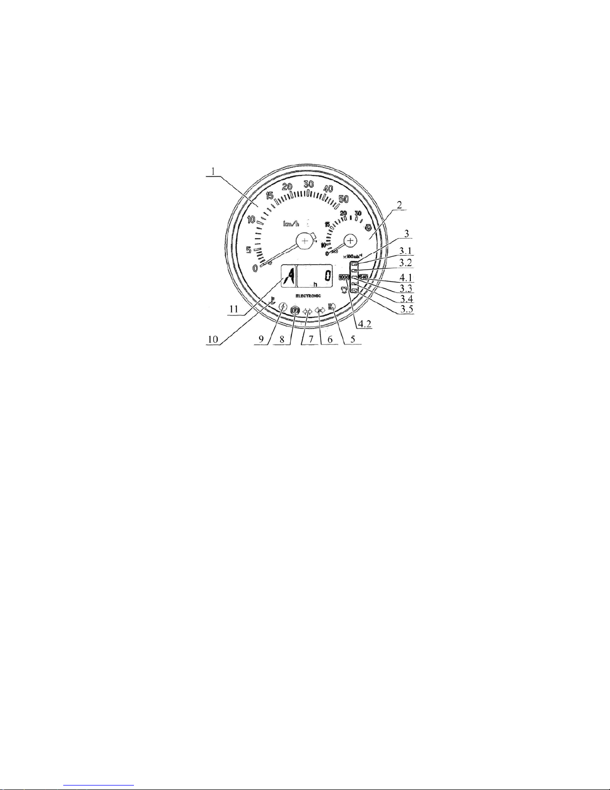
952.5-0000010 OM
30
2.8 Integrated indicator
2.8.1 General information
The integrated indicator 16 (figure 2.1.1) (hereinafter II) and the integrated indicator control
panel 18 (figure 2.1.1) (hereinafter IICP) display information on operational parameters of
systems and units of the tractor and provide operator with data on violation of work or
breakdown of any system.
The II includes gauges and signal lamps as per figure 2.8.1.
1 – velocity gauge (needle indicator);
2 – engine speed gauge (needle indicator);
3 –PTO speed gauge (light indicator);
3.1, 3.5 – segments of PTO speed scale (yellow color);
3.2, 3.3, 3.4 – segments of PTO speed scale (green color);
4.1, 4.2– annunciator of PTO speed scale range (yellow color);
5 – pilot lamp to indicate headlights upper beam switching (blue color);
6 – pilot lamp to indicate switching of trailer turn blinkers (green color);
7 – pilot lamp to indicate switching of tractor turn blinkers (green color);
8 – pilot lamp to indicate parking brake engagement (red color);
9 – pilot lamp to indicate enhanced voltage in on-board system (red color);
10 – pilot lamp to indicate low level of coolant (yellow color);
11 – multifunction display.
Figure 2.8.1– Integrated indicator
2.8.2 Assignment and operation principle of integrated indicator gauges
а) Velocity gauge 1 (figure 2.8.1) indicates a design speed of the tractor on a needle in-
dicator. The design speed exceeds the actual one, as tractor skidding is not taken into account.
The gauge is actuated by signals coming from pulse sensors of rotation frequency of
toothed gears of final drives of right and left rear wheels. The speed is indicated in accordance
with the signal from the sensor installed on the final drive gear of the wheel, turning with a less
speed.
In case one of the speed sensors is faulty the integrated indicator shows speed read-
ings in accordance with the signal coming from the correct sensor. Specific faults of circuits or
speed sensors when the signals from them are missing are displayed in liquid crystal display
as “0” digit, characterizing the fault location – to the right or to the left (see below).
b) The engine speed gauge 2 (figure 2.8.1) indicates rotation frequency of the engine
crankshaft on a needle indicator.
Information on engine speed on tractor BELARUS-952.5 comes from the electronic
control unit. The range of speed readings is from 0 to 3500 (rpm).
Page 31
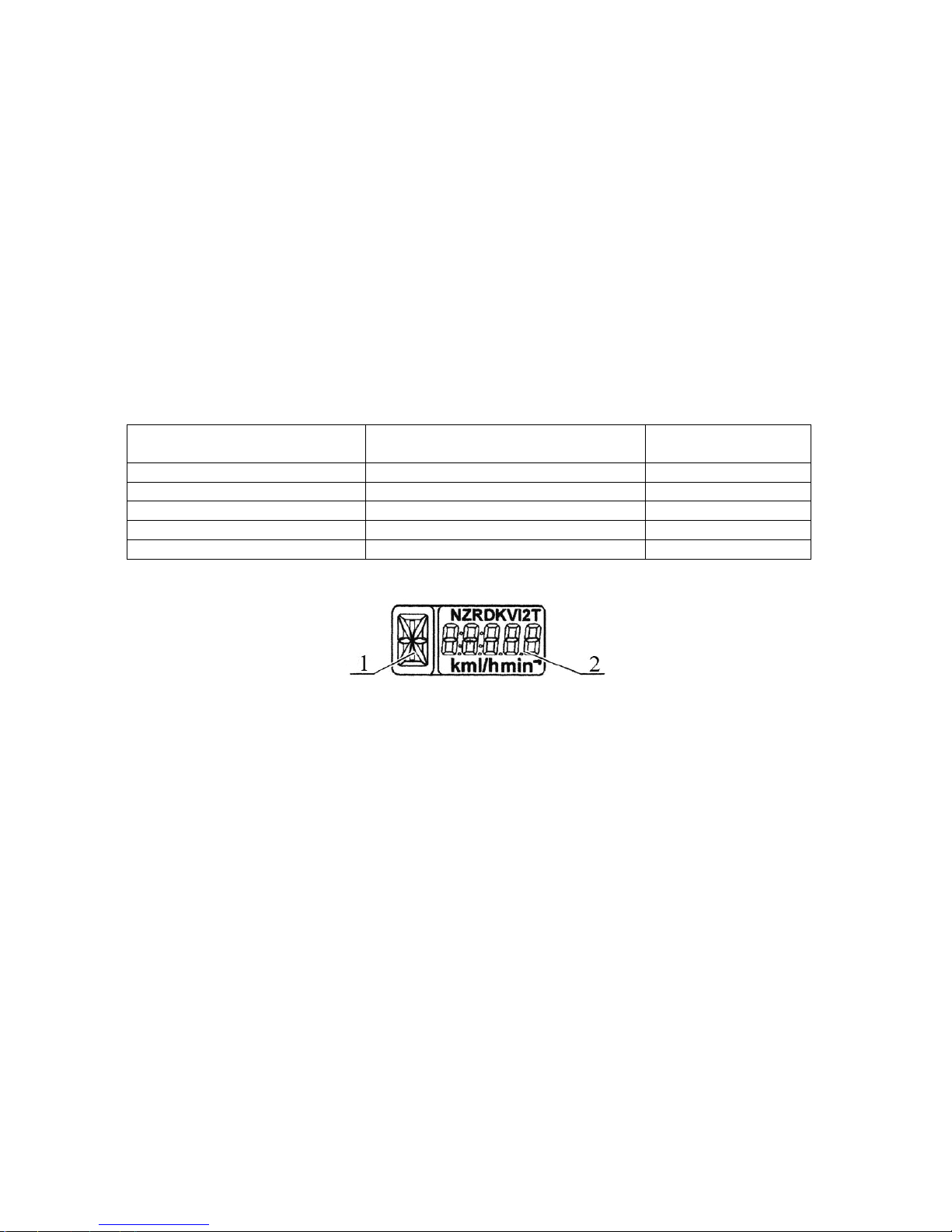
952.5-0000010 OM
31
c) PTO speed gauge 3 (figure 2.8.1) displays the PTO speed on a light indicator.
The rear PTO speed gauge is actuated by frequency signal, resulting from recalcu-
lation of engine speed by means of entered value of index “KV2” (see below), other than
“0”, meanwhile value of index “ZV”, equal to “0”, should be entered (see below).
When II is switched on (see below the description of device functional check) and
engine is running (message “engine speed” from engine control unit is transmitted) identifications of scales “540” and “1000” are illuminated simultaneously.
Indication of PTO scale segment (with regard to the entered value of index “KV2”)
occurs when PTO rated speed, equal to 750 rpm, is achieved.
Indication of lower PTO scale segment (with regard to index “KV2”) occurs when
engine speed of 1400-1500 rpm and above is achieved.
Depending on selected PTO speed mode (540 or 1000) illuminated scale segments
identify value of PTO speed in accordance with given table 2.3.
“PTO speed” mode of liquid-crystal display 11 of multifunctional indicator (Fig.
2.8.1) (see below the description of multifunctional display operation) is not active in this
case.
Table 2.3
«540» «1000» Местоположение
сегмента на шкале
650 1150 3.1
580 1050 3.2
500 950 3.3
420 850 3.4
320 750 3.5
d) The multifunctional display 11 (figure 2.8.1) is a liquid-crystal display that shows information in two fields simultaneously (figure 2.8.3):
1 – digital identification of gear box switch position (digits from 0 to 6) or letter identification
of reduction unit switch position (letters L, M, H, N);
2 – current numeric value of one of tractor system parameters.
Figure 2.8.2 – Information fields of the multifunctional display
Integrated indicator receives information on gear box switch position from transmission
control module (if combined electronic control system (CECS) is available) or from range
reduction unit control module (if available). This parameter is displayed in information field
“1” (Fig. 2.8.2). If control modules are not available or are not connected or wire is broken,
letter “A” is displayed in the information field “1”.
The following parameters are displayed in the information field 2 (figure 2.8.2):
- total elapsed engine time;
- instant fuel flow;
- on-board voltage;
- remaining fuel volume;
- time of running with remaining fuel;
- engine operating time for a selected period;
- testing workability of speed sensors;
- testing workability of frequency fuel volume sensor (FFVS);
- testing workability and connection of CAN-bus to the Integrated Indicator.
Page 32
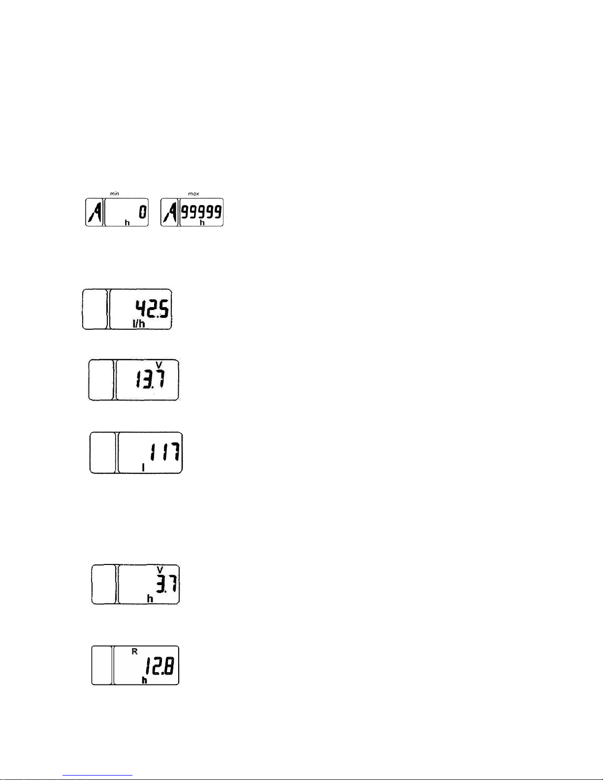
952.5-0000010 OM
32
Switching between indication modes of “Total elapsed engine time “, “Instant fuel
flow”, “Remaining fuel volume”, “Time of running with remaining fuel”, “On-board voltage”,
“Engine operation time for selected period”, and switching between messages on faults
are effected with “Mode” button of the control panel 18 (figure 2.1.1). Description of mode
operation algorithms„Testing workability of speed sensors”, “Testing workability of frequency fuel volume sensor (FFVS)”, “testing workability and connection of CAN-bus to the
Integrated Indicator” is given below.
1. Total elapsed engine time, h
The counter accumulates information on the total
elapsed engine time with uploading a message “engine
speed” from the engine control unit and stores it when
the power supply is off. The range of engine time indica-
tions is from 0 to 99999 hours.
2. Instant fuel flow, l/h
In this mode a current value of the instant fuel flow with a resolution
of 0,1 l/h is displayed.
3. On-board voltage, V
In this mode a current value of on-board voltage with an accuracy of
0,1 V is displayed in a digital form.
4. Remaining fuel volume in the tank, l
In this mode a current fuel volume remaining in the tank is displayed in liters.
This mode is available only when the tractor is stopped (i.e. when
there are no signals from the speed sensors).
Note: Tractor should be stopped on horizontal surface in order to increase displaying accuracy of fuel amount in tank.
5. Time of running on remaining fuel, h
In this mode assessed engine time, calculated for current values of
the instant fuel flow and remaining fuel volume is displayed, (indication increment is 0.1 hour).
6. Engine operation time for selected period
In this mode engine operation time with 1/10-of-an-hour accuracy for a
selected period of operation is displayed. If required it is possible to zero
the counter value by way of pressing the “Mode” button and keeping it
pressed for at least 2 sec.
Page 33
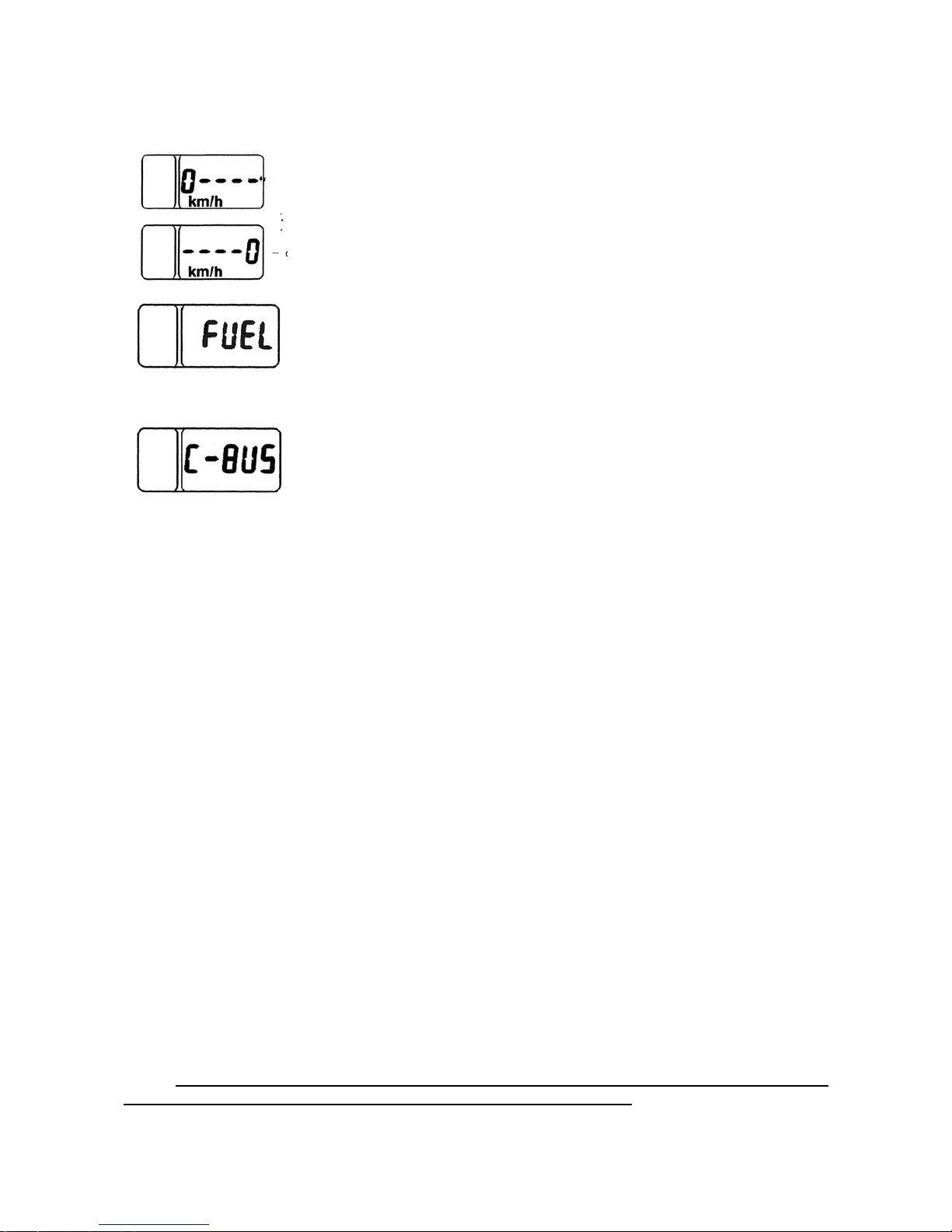
952.5-0000010 OM
33
II in the mode of failure messages displaying
1. Testing workability and connection of speed sensors:
In case there are no signals coming from the speed
sensor for 10-12 sec. a message in the form of “0” digit
is displayed on liquid-crystal display characterizing the
location of the faulty sensor (left or right)
2. Testing workability of the frequency fuel volume sensor:
If there is no signal coming from the frequency fuel volume sensor
for two sec. a message “FUEL” is displayed on the screen.
3. Testing workability and connection of CAN-bus to the Integrated Indicator with
CAN-interface:
If there are no signals through CAN-bus of the integrated indicator a
message “C-BUS” appears on the screen.
Each of the fault messages (Example: 0----, FUEL, C-BUS) is displayed in priority
on the LCD-display irrespective of the information currently displayed. With sequential
pushing the “Mode” button of the integrated indicator control module the messages shall
be listed in turn. After the last message has been viewed and the “Mode” button has been
repeatedly pressed the LCD - display changes into displaying the cyclic mode of the operating parameters specified before.
The fault messages are displayed on the LCD-screen every time the device is actuated until the cause is eliminated.
When the integrated indicator is powered-on the multifunctional display shows information in the indication mode which has been chosen before the moment of powering
off the integrated indicator.
If there is no information on parameter values, which are received from ECU only,
corresponding indication modes switch off automatically.
2.8.3 Pilot lamps of the integrated indicator
ATTENTION: PILOT SIGNALING LAMS ARE ACTIVATED AND DEACTIVATED
SYNCHRONOUSLY WITH CHANGING THE STATE OF SYSTEM SENSORS!
а) 5 (figure 2.8.1) - pilot lamp to indicate switching on the road lights upper beam
lights up when switching on the upper beam;
b) 6, 7 (Figure 2.8.1) - indicators of tractor turns and trailer turns operate in a flash-
ing mode when actuated with the underwheel multifunctional switch 10 (figure 2.8.1) or
when the emergency button is pushed in;
c) 8 (Figure 2.8.1) pilot lamp to indicate the parking brake is enabled. 14 The pilot
lamp “Parking brake” operates in a flashing mode with 1 Hz frequency when the parking
brake sensor goes off;
d) 9 (Figure 2.8.1) –pilot lamp to indicate increased on-board voltage gets activated
when the tractor on-board supply voltage goes up above 19V and goes out when the voltage falls below 17V;
In this case II switches off completely, and recovers its operational capability when
the voltage goes down to rated value of on-board system voltage.
e) 10 (Figure 2.8.1) – pilot lamp to indicate low level of coolant (is not used).
left wheel sensor
right wheel sensor
Page 34
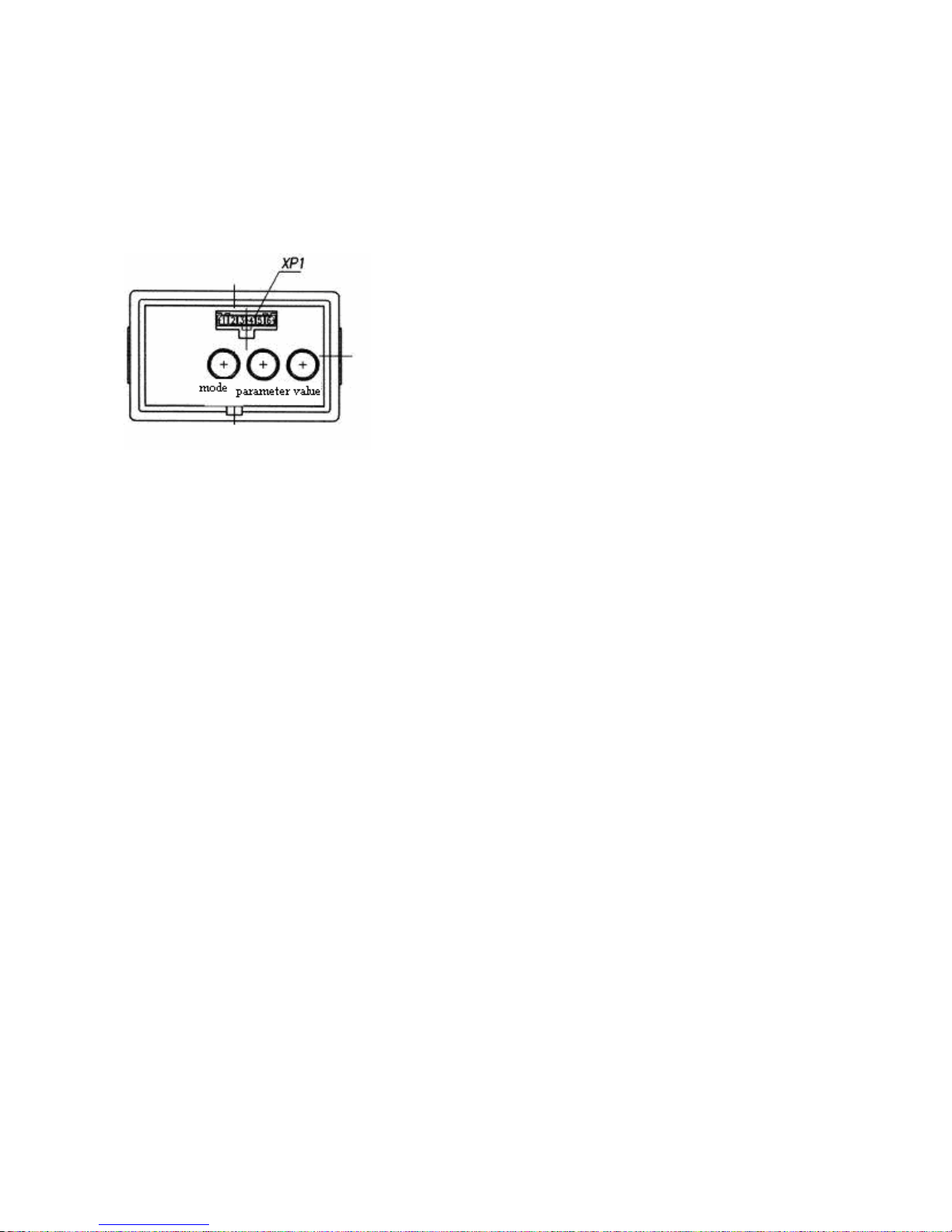
952.5-0000010 OM
34
2.8.4 Description of testing the indicator performance
Each time the power supply is on, performance testing of needle pointers and scale
elements of the PTO indicator is carried out in the integrated indicator. Herewith the indicator needle pointers move away from initial marks and run over the first following digitized
scale marks (over “5” for the speed and over “10” for revolutions), and all segments and
indications “540” and “1000” of PTO scale are activated.
2.8.5 Programming panel of integrated indicator
The programming panel 18 (figure 2.1.1) makes it possible
to perform manual programming of the indicator by means
of “Parameter” and “Value” buttons (figure 2.8.3) and to
change the mode of displaying the parameters to be shown
on the LCD.
Note - A diagnostic connector ХР1, located on the front
surface of the control panel, makes it possible to perform
automatic programming (reprogramming) of the integrated
indicator (II) by means of a special device (if provided).
Should such a device be unavailable, the programming
shall be performed by means of the above
mentioned buttons. On “BELARUS-952.5” tractors, the
ХР1 connector is not enabled.
Figure 2.8.3 – Programming panel of integrated indicator
Algorithm of integrated indicator programming
1. When selecting a fixed value of programming parameter:
1.1 When the “Parameter” button is pressed for the first time (see Figure 2.8.3), the LCD
switches to the mode of viewing the programmed parameter and its numerical value.
When the button is pressed repeatedly, the parameters are alternated cyclically.
1.2 When the “Value” button is pressed repeatedly (see Figure 2.8.3), the numerical value
of the set programmed parameter is changed.
1.3 When neither the “Parameter” nor “Value” button is pressed for 7.0 seconds, the mode
is exited automatically.
When exiting the mode, the parameter values selected with the “Value” button are stored.
2. When inputting an unfixed value of programming parameter:
2.1 Press the “Parameter” button to select the parameter the value of which is to be set;
2.2 Twice press the “Mode” button, the low-order digit on the LCD screen will start blinking;
2.3 To change the blinking digit of the parameter, press the “Value” button;
2.4 To select the high-order digit, press the “Parameter” button;
2.5 To exit the programming mode of an unfixed value of any parameter, press the “Mode”
button twice;
2.6 After the said mode is exited, the digits of the input value of the parameter stop blinking.
2.7 The newly set value is put the last in the list of allowed ones for programming the parameter values;
Notes:
- when the “Mode” button is pressed once in the programming mode, input of an
arbitrary parameter value is not possible;
- when none of the “Mode”, “Parameter”, “Value” buttons is pressed for seven seconds in the mode of unfixed value input, the ID automatically switches to the main LCD
mode, and all set parameter values are stored.
Page 35
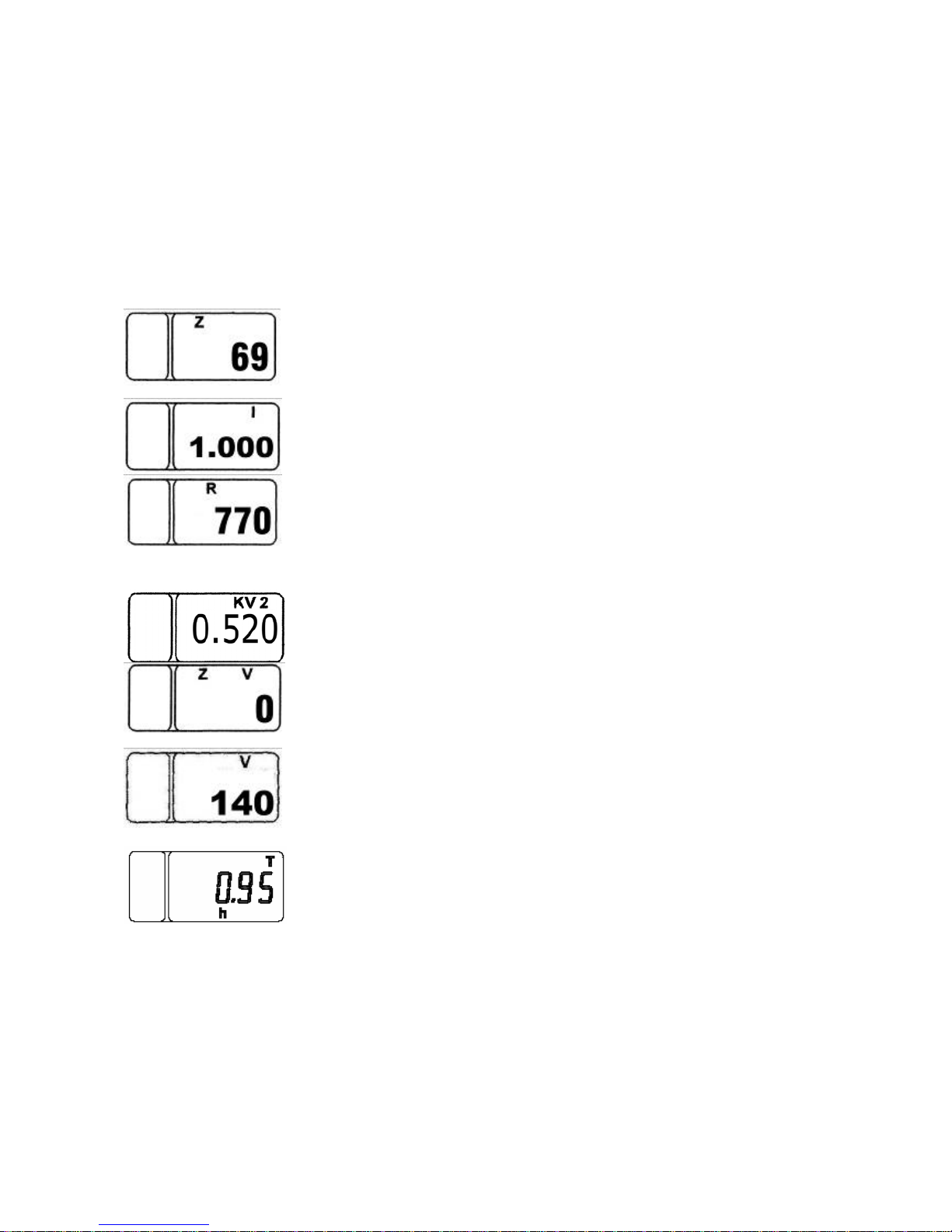
952.5-0000010 OM
35
One unfixed value can be input in a range:
for “Z” - 23 to 69;
for “I” - 1,000 to 4,000;
for “R” - 400 to 1000;
for “K” - 2,360 to 4,000; (For an ID without a CAN interface)
for “KV2” - 0.346 to 0.600;
for “ZV” - 12 to 78;
for “V” - 0 to 600;
List of programmed ratios (graphic examples of parameter presentations and their
values in the programming mode):
“Z” parameter
Z is the number of teeth of final shaft gears of the driving wheels
(right and left), over which the travel speed (rotation speed) sensors are installed.
“I” parameter
I is the gear ratio multiplier of the wheel-hub drive.
“К” parameter
R is the rear axle rolling radius, mm. When reprogramming, this
parameter can be modified with a 5 mm step.
Note 770 is the value for tires 18.4R34. If other tire types are installed, set the “R” value corresponding to the rolling radius of the
installed tires.
“KV2” parameter
KV2 is the PTO gear ratio.
“ZV” parameter
ZV is the teeth number of the PTO speed sensor gear
(Note – if a sensor is not installed, input “0”).
“V” parameter
V is the fuel tank volume, l.
Note – 140 liters – fuel tank volume on tractors with RLL with hydraulic
lift. On tractors equipped with RLL with draft control unit the fuel tank
volume makes 130 liters.
Also, when the “Parameter” button is pressed in the programming
mode, the list of programmed parameters contains an independent
“T” parameter of precise readout of the astronomic service hours
of the engine. This parameter cannot be modified, it is the precise
number (to 1/10 of hour) of engine service hours.
During operation, it is allowed to modify the failure of the parameter of wheel rolling radius
“R”, which is determined based on the tires installed on the tractor by measuring the distance from
the wheel center to the reference surface.
DO NOT MODIFY THE ENTERED VALUES OF ALL OTHER PARAMETERS (FACTORY
DEFAULTS).
When the instrument scale illumination is on, i.e. when the central light switch 22 (Figure
2.1.1) is switched to the position II “Instrument panel illumination, clearance lamps ON” and to the
position III “Consumers of the position II and front headlights ON”, the brightness of the display of
the PTO indicator segments is automatically reduced.
Page 36
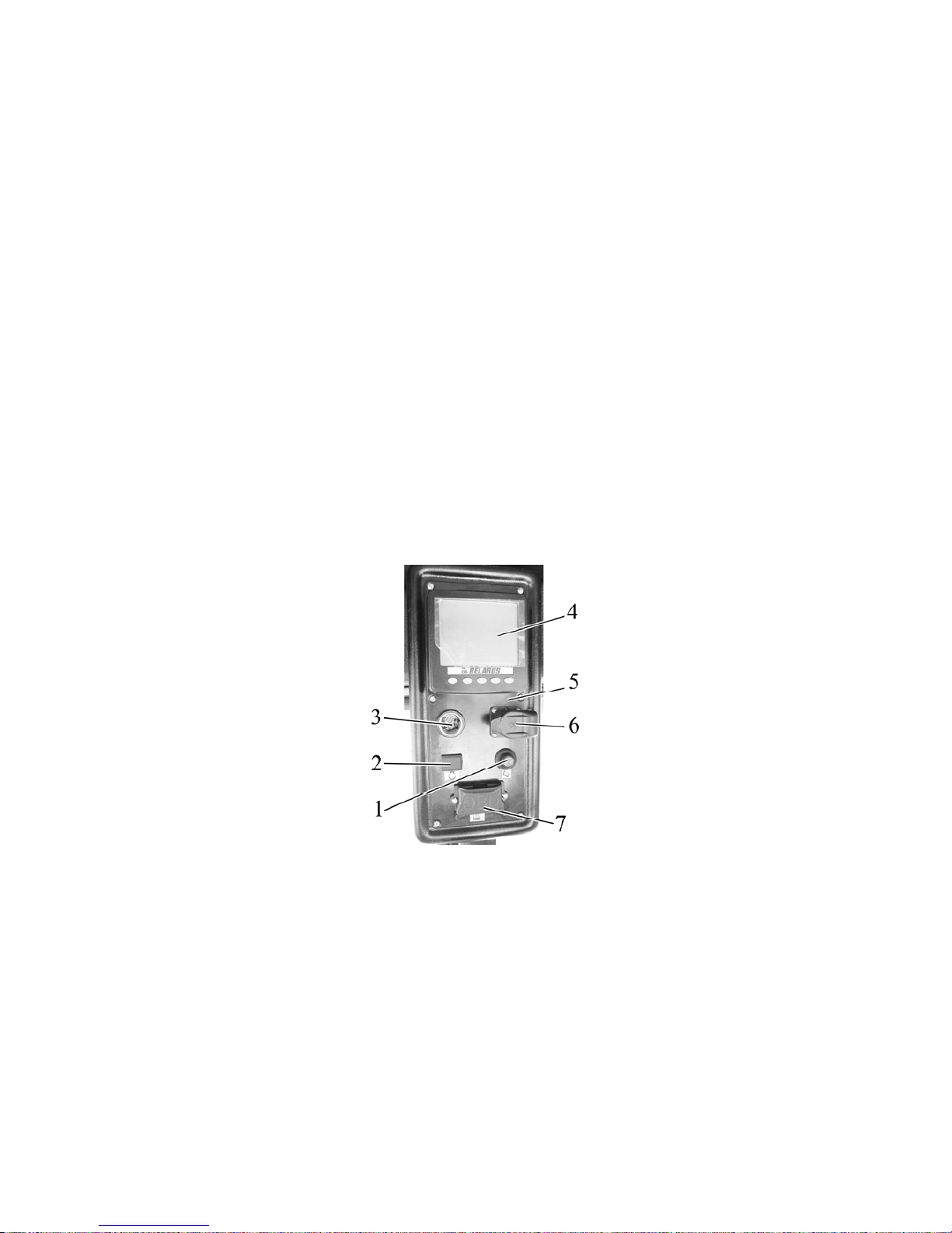
952.5-0000010 OM
36
2.9 Engine control panel
2.9.1 General information
The engine control panel 5 (Figure 2.9.1) includes a button switch of testing activation 1, a fault testing annunciator 2, a cigarette lighter 3, an information display 4, electrical
receptacle 12V/25А 6, testing jack 7.
The button switch of testing activation 1 is intended to call up active errors form the
memory of the engine electronic control unit by means of light codes, displayed by the fault
testing annunciator 2. This way of testing is alternative in comparison with information display 4. Regarding reading and decoding light errors as well as fault elimination refer to the
engine operation manual, attached to your tractor. The eliminated errors are to be eliminated. To eliminate the detected faults, please, contact your dealer.
After the key of the starter and instrument switch is turned from the position “Off” into the
position “Instruments are on”, the system is powered. After the system has been powered it
carries out a self-check. If there are no errors in the operation of the system the fault testing
annunciator 2 on the panel of engine control system shall turn on and go out, thus testifying of
workability of the annunciator 2 lamp and its correct connection to the tractor on-board system.
A special testing jack 7 is intended for connection of system testing devices to carry
out an extended service diagnostics of the engine under operation. The named system
testing devices are recommended for dealer centers.
1 – button switch of testing activation; 2 – fault testing annunciator; 3 – cigarette
lighter; 4 – information display; 5 –engine control panel; 6 –electrical receptacle 12 V/25 А;
7 – testing jack.
Figure 2.9.1 – Panel of engine control system
2.9.2 Information display
2.9.2.1 General information
The information display 4 (figure 2.9.1) is designed to display engine actual parame-
ters and indication of the engine electronic control system (EECS) faults.
When the key of starter and instrument switch is set into “I” position supply voltage
is delivered to the engine electronic control system. After the supply voltage is delivered
the EECS constantly performs self-testing. If there are no faults in the EECS operation, the
information display functions in a working mode – it displays actual parameters of engine
operation.
Page 37
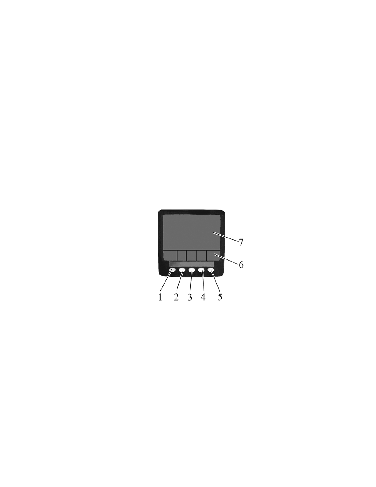
952.5-0000010 OM
37
When the error is defined, the information display produces an acoustic signal and a
brief description of the identified errors appears on the screen, also a fault testing annunciator lights up or flashes on the engine control panel 5. Interpretation of error codes as
well as recommended actions to be taken to eliminate the identified faults are given in the
engine operation book attached to your tractor.
ATTENTION: THE ERRORS IDENTIFIED ARE TO BE ELIMINATED! TO
ELIMINATE THE ERRORS CONTACT YOUR DEALER!
2.9.2.2 Adjustment of brightness and sharpness of the information display
To enter the mode of adjustment of screen brightness and sharpness 7 (figure
2.9.2) press button 5. In the screen lower part images of buttons are given. Pressing button 1 decreases brightness, pressing button 2 increases brightness, pressing button 3 decreases sharpness, pressing button 4 increases sharpness, and pressing buttons 1,2,3,4
simultaneously adjusts to an average value of sharpness and max. brightness. Repeated
pressing button 5 exits the mode of brightness and sharpness adjustment.
2.9.2.3 Call up of changeable images and parameters on the screen of the information display
1 – button to activate the main (three-segment) image and choose between dis-
played parameters; 2 – button to activate four-section image and choose between displayed parameters; 3 – button to activate graphic display and choose between displayed
parameters; 4 – button to activate indication of error (fault) list and choose between displayed parameters; 5 – button to enter/exit the mode of adjustment of sharpness, brightness and configuration menu; 6 – changeable display of buttons functional purpose; 7 –
screen.
Figure 2.9.2 – Information display
Page 38
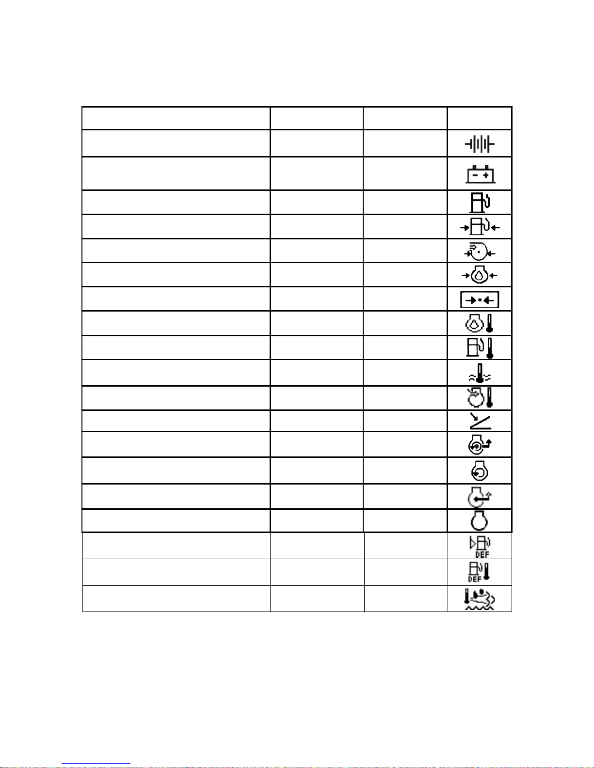
952.5-0000010 OM
38
Table 2.4 – Lift of parameters of four-segment and graphic indication of engine op-
eration
Parameters
Four-segment
imaging
Graphic
imaging
Symbol
Electric voltage directly on terminals of
information monitor connection, V
7. 8.
Voltage on the terminals of the accumulator battery, measured by the
engine electronic control unit, V
9. 10.
Fuel flow, l/h 9 9
Fuel delivery pressure, kPa 9 9
Air pressure at the inlet pipe, kPa 9 9
Oil pressure in engine, kPa 9 9
Barometer pressure, kPa 9
Engine oil temperature, °С
9 9
Fuel temperature, °С
9
Temperature of coolant in the engine, °С
9 9
Air temperature at the inlet pipe, °С 9 9
Accelerator position, % 9
Use of turning torque, rpm 9
Engine torque, requested by the
driver,%
9
Torque consumption, % 9
Engine speed, rpm 9 9
AdBlue level in the tank, %
9
AdBlue temperature in the tank, %
9
Temperature of exhausts before the
SCR catalyst, °С
9
Page 39

952.5-0000010 OM
39
The monitor buttons 1, 2, 3, 4, 5 (figure 2.9.2) are of multifunctional purpose. When
pushing any of the buttons 2, 3, 4 during the monitor operation, an image of the button
panel 6 appears on the screen, the icons denoting the current functions of each button.
Pressing the button 1 on the monitor activates the main three-segment image on the
screen. Hereby an engine speed scale is displayed in the upper left corner, and a scale of
oil pressure in the engine lubrication system in the upper right corner, cooling fluid temperature in the lower right corner, current fuel flow per hour in the lower left corner. When
the three-segment imaging is indicated the displayed parameters in the lower left corner
are chosen between with the button 1. To exit the mode of choosing between the displayed parameters in the upper right corner it is required to press button 5 after activation
of the button panel 6. After that the parameters are chosen between with the
buttons 1 and 2.
After the button panel 6 has been called up a four-segment imaging of parameters
on the screen 7 is activated with the button 2. After the first pressing the button 2 four parameters are displayed in a digital mode on the screen:
- in the upper left corner – engine speed;
- in the upper right corner – coolant temperature;
- in the lower left corner – on-board voltage;
- in the lower right corner – oil pressure in the lubrication system.
When pressing the button 2 for the second and the third time, four parameters are
displayed on the screen in an analog from.
Using the mode of choosing between displayed parameters the customer can activate, if necessary, displaying of various engine parameters on the screen as per table 2.4.
The mode of parameter choosing is activated after calling up of the button panel with
short-time pressing the button 5. Sequential pressing the button 1 changes the parameters
displayed in the upper left corner, pressing the button 2 changes the parameters in the upper right corner, button 3 – in the lower left corner, button 4 – in the lower right corner. The
parameter choosing mode is exited with short-time pressing the button 5.
As the button panel has been called up pressing the button 3 activates graphical
displaying of parameters in the course of time (functions as parameter analogue recorder).
The required parameters are chosen with a sequential pressing the button 3 as per
table 2.4.
A temporary net can be adjusted in a configuration menu from 2, 10 or 30 min. to 1,
2, 4 or 8 hours. To enter the configuration menu it is necessary to press the button 5 for
more than 3 sec. Also it is possible to choose metric and British units of measurement in
this menu, among available languages it is possible to choose English, Spanish, Swedish,
French, German, Italian, Dutch, Portuguese and Russian.
ATTENTION: ONLY DEALERS ARE AUTHORIZED TO CHANGE SETTINGS OF
CONFIGURATION MENU!
When errors (faults) are detected during operation the monitor produces a sound
signal and a rhombic flashing window with an exclamation mark appears on the screen.
After the button panel has been called up a list of active errors (faults) is invoked
with the button 4. Moving over the list is carried out with the button 1 and 2.
To exit displaying of the lift of active errors it is necessary to confirm reception of all
errors by pressing the button 3. After the errors stop to come into the display they are
automatically deleted from the list.
Page 40
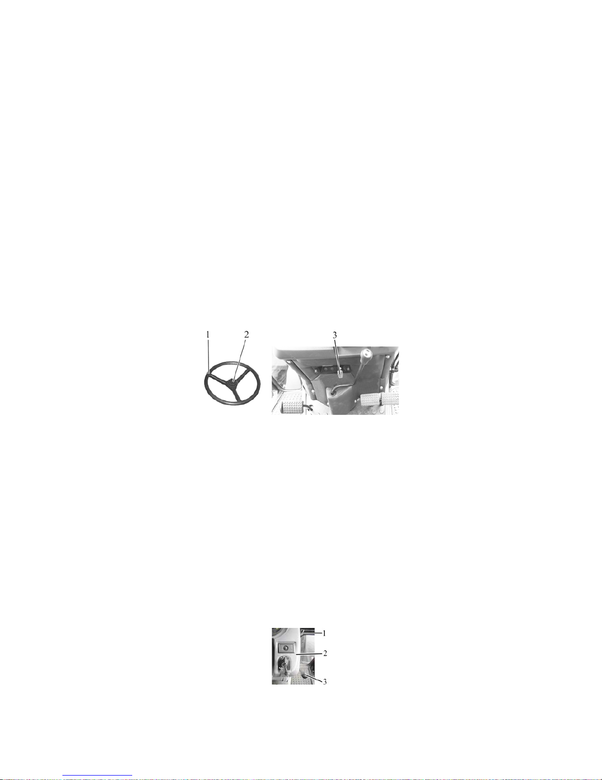
952.5-0000010 OM
40
2.10 Steering
2.10.1 General information
The “BELARUS-952.5” tractor is equipped with hydrostatic steering control (HSC).
When the engine is stopped the HSC feed pump, driven by the engine crankshaft, does not
feed the hydraulic system of the HSC and it is automatically shifted to a manual mode, which
requires application of a greater effort on the steering wheel in order to turn the tractor.
2.10.2 Steering wheel adjustments
The steering wheel has the following adjustments:
- horizon tilt angle adjustment;
- height adjustment, along steering shaft axis.
To change height positioning of the steering wheel proceed as follows:
- unscrew the chuck 2 (figure 2.10.1) by 3-5 revolutions;
- set the wheel 1 to a position comfortable for work;
- screw in the chuck 2 with max. possible force of hand fingers.
The range of the steering wheel height adjustment is 100 mm, stepless.
To change the steering column tilt angle do the following:
- pull the handle 3.
- tilt the steering column to reach the position comfortable for work and releasing the
handle 3 swing the steering column smoothly in longitudinal direction until fixed firmly.
The steering column can be tilted and fixed in four positions from 25° to 40° with 5° interval.
1 – steering wheel; 2 – chuck; 3 – handle to fix tilt of the steering column.
Figure 2.10.1 Steering wheel adjustment
2.11 Parking brake control
Upper position of the lever 37 (figure 2.1.1) – parking brake “On”;
Lower position of the lever 37 – parking brake “Off”.
To disengage the parking brake press the control lever button and let the lever 37
down against the stop.
2.12 Handle for fuel feed manual control
When the handle 42 (figure 2.1.1) is moved to the extreme front position, fuel is fed to the max,
when the handle is moved to the extreme rear position – fuel is fed to the min. in accordance with
the minimum idle speed.
If tractor is equipped with HLL outputs control by means of joystick and lever, the handle of manual
feed control 3 (figure 2.12.1) is mounted on dashboard 2 facing to the right. The front end position
of the handle 3 – is max. fuel feed, at handle 3 movement into end rear position – min. fuel feed.
1 – instruction plate of fuel feed control; 2 – dashboard; 3 –handle of manual feed control.
Figure 2.12.1 – Manual feed control handle assembly at HLL control by means joystick
and lever
Page 41
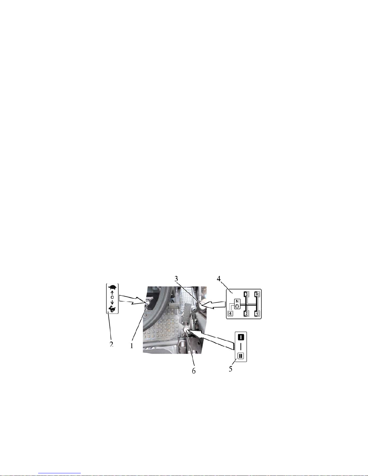
952.5-0000010 OM
41
2.13 Tractor pedals
2.13.1 Pressing the pedal 24 (figure 2.1.1) disengages the clutch.
2.13.2 Pressing the pedal 27 (figure 2.1.1) brakes the rear left wheel.
2.13.3 Pressing the pedal 28 (figure 2.1.1) brakes the rear right wheel. A joint plate
of the brake pedals is intended for simultaneous braking with the right and left brakes.
2.13.4 Pressing the pedal 29 (figure 2.1.1) increases the engine speed.
2.14 Gear shifting
2.14.1 General information
In a basic configuration of the BELARUS-952.5 tractor transmission is mounted a synchromesh gearbox with double-lever control and speed-increase gear unit (GB 14F + 4R).
Against order it is possible to equip the tractor BELARUS-952.5 with following configurations
of the transmission:
- synchromesh gearbox with single-lever control and speed-increase gear unit (GB 14F+4R);
- synchromesh gearbox with double-lever control and reverse gear unit (GB 7F+6R);
- synchromesh gearbox with single-lever control and reverse gear unit (GB 7F+6R).
2.14.2 Gears shifting in the transmission with a double-lever GB control and speedincrease gear unit
The gears are shifted by three levers: lever to shift ranges of gearbox 6 (figure 2.14.1), lever to
shift gears of GB 3 and control lever of the speed-increase gear unit 1.
The required ranges, gears and passes of the speed-increase gear unit (decelerating pass "turtle", accelerating pass - "hare") are set as per the scheme 5, 4 and 2 as it is shown in
figure 2.14.1.
The ranges and gears are set by special levers 6 and 3. First set the range (I-st or II-nd) with
lever 6, then set necessary gear with lever 3.
Lever to shift ranges of gearbox does not have fixed neutral position, therefore the I-st or the
II-nd range of gearbox is always on.
During tractor operation the control lever of the speed-increase gear unit 1 shall be in
switched-on position (fixed): back - accelerating pass ("hare") or forward - decelerating pass
("turtle"). It’s allowed to hold the control lever of the speed-increase gear unit in a neutral position (middle, non-fixed) to make easier the engine start at low temperature.
1 – control lever of the speed-increase gear unit; 2 – diagram of passes shifting of the speedincrease gear unit; 3 – lever to shift gears; 4 – diagram of gears shifting; 5 – diagram of gearbox
ranges shifting; 6 – lever to shift ranges of the GB.
Figure 2.14.1 – Gearbox with double-lever control and speed-increase gear unit
ATTENTION: YOU CAN GET INTO FOURTH GEAR ONLY IF THE IInd RANGE IS SET!
Page 42
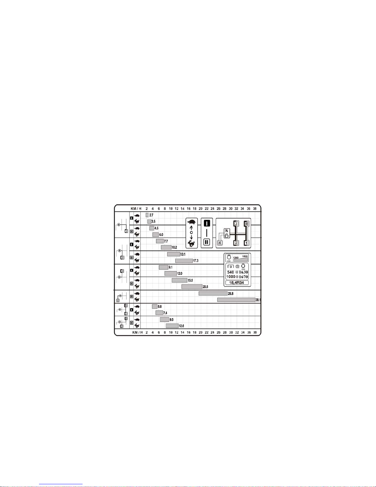
952.5-0000010 OM
42
ATTENTION: SHIFT RANGES AND GEARS OF THE GEARBOX ONLY WITH THE TRACTOR STOPPED AND THE CLUTCH PEDAL FULLY DEPRESSED! PERFORMING TRANSPORT OPERATION IT IS PERMITTED TO SHIFT GEARS IN MOTION FROM THE SECOND
TO THE THIRD, FROM THE THIRD TO THE SECOND WITHIN THE I
st
AND THE II
nd
RANGE, AND ALSO FROM THE SECOND TO THE FOURTH, FROM THE FOURTH TO THE
SECOND, FROM THE THIRD TO THE FOURTH, FROM THE FOURTH TO THE THIRD
WITHIN THE II
nd
RANGE. THE SHIFTING SHALL BE CARRIED OUT WHEN THE TRACTOR
COASTS AND THE CLUTCH PEDAL IS FULLY DEPRESSED! ENGAGEMENT AND DISENGAGEMENT OF THE FIRST GEAR, DOWNSHIFTING TO THE FIRST GEAR, ENGAGEMENT AND DISENGAGEMENT OF THE REVERSE GEAR SHALL BE CARRIED OUT ONLY
WITH THE TRACTOR FULLY STOPPED AND WITH THE CLUTCH PEDAL FULLY DEPRESSED.
ATTENTION: THE PASSES OF THE SPEED-INCREASE GEAR UNIT CAN BE SHIFTED IN ANY GB
GEAR ONLY WITH THE TRACTOR STOPPED AND THE CLUTCH PEDAL FULLY DEPRESSED. PERFORMING TRANSPORT OPERATION IT IS PERMITTED TO SHIFT PASSES
OF THE SPEED-INCREASE GEAR UNIT IN MOTION AS THE TRACTOR COASTS AND THE
CLUTCH PEDAL IS FULLY DEPRESSED!
The velocity diagram table of “BELARUS-952.5” tractor equipped with double-lever GB control
and speed-increase gear unit on tires of basic configuration is attached to the cab right window
and is shown in Figure 2.14.2.
Figure 2.14.2 – The velocity diagram of “BELARUS-952.5” tractor equipped with
double-lever GB control and speed-increase unit
2.14.3 Gear shifting in transmission with a single-lever GB control and speed-increase
gear unit
The gears are shifted by two levers: lever to shift ranges and gears of gearbox 3
(figure 2.14.1) and control lever of the speed-increase gear unit 2.
The required ranges, gears and passes of the speed-increase gear unit (decelerating pass "turtle", accelerating pass - "hare") are set as per scheme 4 and 1 as it is shown in Figure
2.14.3.
The gears and ranges are shifted by one lever 3, at that first is set the range (I-st or II-nd) ,
then the lever is set in a position «N», so you engage a required gear.
During tractor operation control lever of the speed-increase gear unit 2 shall be in switched-on
position (fixed): reverse - accelerating pass ("hare"), or forward - decelerating pass ("turtle").
It’s allowed to hold the control lever of the speed-increase gear unit in a neutral position (middle, non-fixed) to make easier the engine start at low temperature.
Page 43
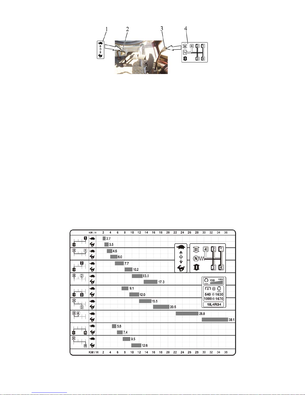
952.5-0000010 OM
43
1 – diagram of passes shifting of the speed-increase gear unit; 2 – control lever of the
speed-increase gear unit; 3 – lever to shift ranges and gears of the GB; 4 – diagram of gearbox
ranges and gears shifting.
Figure 2.14.3 – Gearbox control with single-lever and speed-increase gear unit
ATTENTION: YOU CAN ENGAGE THE FOURTH GEAR OF GB ONLY IF THE IInd RANGE
OF GB IS SET!
ATTENTION: SHIFT RANGES AND GEARS OF THE GEARBOX ONLY WITH THE TRACTOR STOPPED AND THE CLUTCH PEDAL FULLY DEPRESSED! PERFORMING TRANSPORT OPERATION IT IS PERMITTED TO SHIFT GEARS IN MOTION FROM THE SECOND
TO THE THIRD, FROM THE THIRD TO THE SECOND WITHIN THE I
st
AND THE II
nd
RANGE, AND ALSO FROM THE SECOND TO THE FOURTH, FROM THE FOURTH TO THE
SECOND, FROM THE THIRD TO THE FOURTH, FROM THE FOURTH TO THE THIRD
WITHIN THE II
nd
RANGE. THE SHIFTING SHALL BE CARRIED OUT AS THE TRACTOR
COASTS AND THE CLUTCH PEDAL FULLY DEPRESSED! ENGAGEMENT AND DISENGAGEMENT THE FIRST GEAR, DOWNSHIFTING TO THE FIRST GEAR, ENGAGEMENT
AND DISENGAGEMENT THE REVERSE GEAR SHALL BE CARRIED OUT ONLY WITH
THE TRACTOR FULLY STOPPED AND WITH THE CLUTCH PEDAL FULLY DEPRESSED.
ATTENTION: PASSES OF THE SPEED-INCREASE GEAR UNIT CAN BE SHIFTED IN ANY GEAR OF
GB ONLY WITH THE TRACTOR STOPPED AND THE CLUTCH PEDAL FULLY DEPRESSED.
PERFORMING TRANSPORT OPERATION IT IS PERMITTED TO SHIFT PASSES OF THE
SPEED-INCREASE GEAR UNIT IN MOTION AS THE TRACTOR COASTS AND THE CLUTCH
PEDAL FULLY DEPRESSED!
The velocity diagram table of “BELARUS-952.5” tractor equipped with single-lever GB control
and speed-increase unit on tires of basic configuration is attached to the cab right window and
is shown in figure 2.14.4.
Figure 2.14.4 – “BELARUS-952.5” tractor velocity diagram with single-lever GB
control and speed increase unit
Page 44
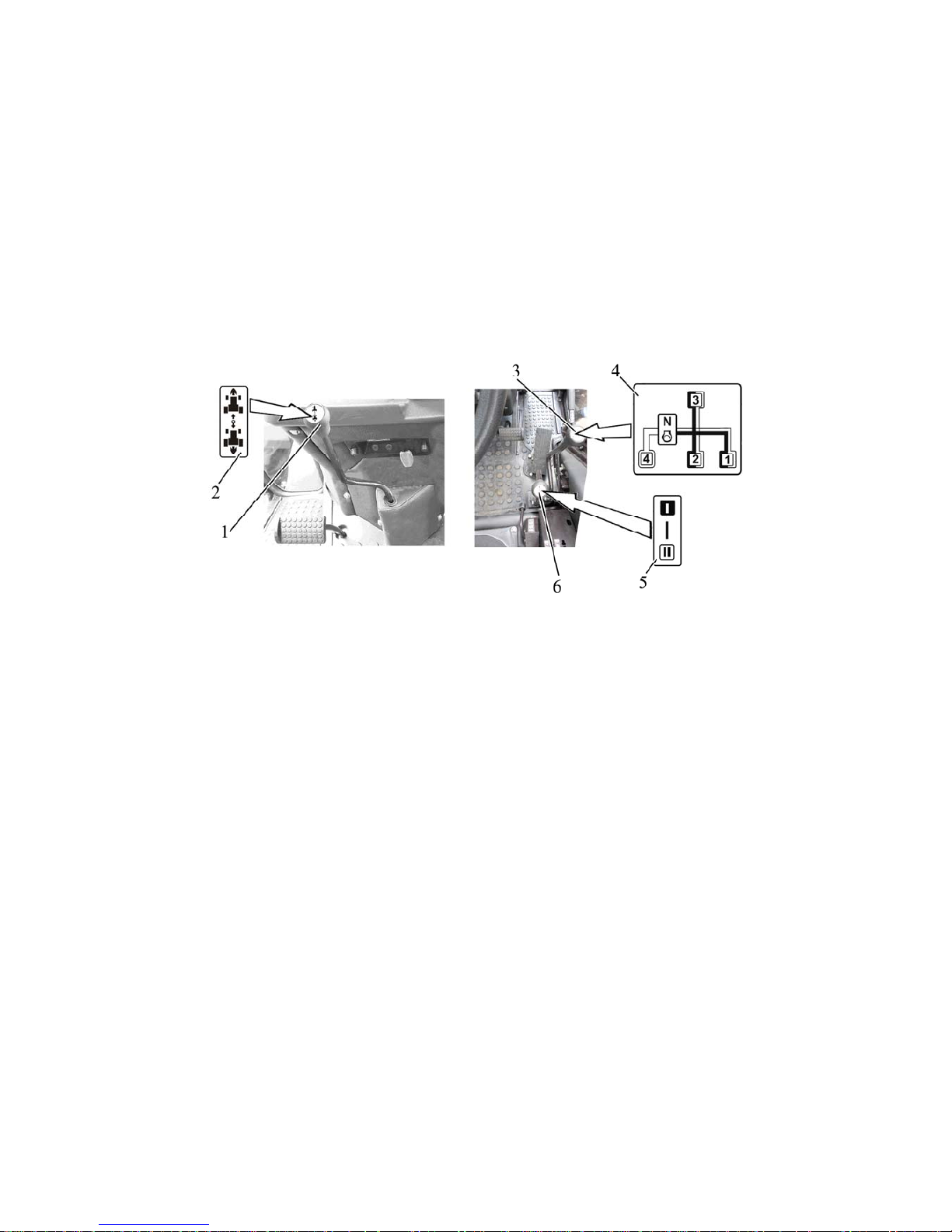
952.5-0000010 OM
44
2.14.4 Gears shifting in transmission with double-lever GB control and reverse gear
unit
The gears are set by three levers: lever to shift ranges of gearbox 6 (figure 2.14.5), lever to
shift gears of GB 3 and control lever of the reverse gear unit 1.
The required ranges, gears and passes of the reverse gear unit (forward motion pass – symbol
"forward", reverse motion pass – symbol "reverse") are set as per the scheme 5, 4 and 2 as it
is shown in Figure 2.14.5.
Gearbox ranges and gears are shifted by separate levers 6 and 3. First set the range (I-st or
II-nd) with lever 6, then engage a required gear with lever 3.
Lever to shift ranges of gearbox does not have a fixed neutral position, therefore the I-st or the
II-nd range of gearbox is always on.
During tractor operation the control lever of the reverse gear unit 1 shall be in switched-on position (fixed): forward –forward motion pass (“forward”), or reverse –reverse motion pass (“reverse”). It’s allowed to hold the control lever of the reverse gear unit in a neutral position (middle, non-fixed) to make easier the engine start at low temperature.
1 – control lever of the reverse gear unit; 2 – diagram of passes shifting of the reverse gear
unit; 3 – lever to shift gears; 4 – diagram of gears shifting; 5 – diagram of gear box passes shifting ;
6 – lever to shift ranges of the gearbox.
Figure 2.14.5 – Gearbox control with double-lever and reverse gear unit
ATTENTION: GEARBOX OF THE TRACTOR EQUIPPED WITH THE REVERSE
GEAR UNIT DOES NOT HAVE A REVERSE GEAR. YOU CHOOSE THE DIRECTION OF
MOVEMENT BY SHIFTING THE CORRESPONDENT PASS OF THE REVERSE GEAR
UNIT.
ATTENTION: YOU CAN ENGAGE THE FOURTH GEAR OF GB ONLY IF THE II
nd
RANGE OF GB AT FORWARD MOTION IS SET!
ATTENTION: SHIFT RANGES AND GEARS OF THE GEARBOX ONLY WITH THE
TRACTOR STOPPED AND THE CLUTCH PEDAL FULLY DEPRESSED. PERFORMING
TRANSPORT OPERATION IT IS PERMITTED TO SHIFT GEARS IN MOTION FROM THE
SECOND TO THE THIRD, FROM THE THIRD TO THE SECOND WITHIN THE I
st
AND THE
II
nd
RANGE, AND ALSO FROM THE SECOND TO THE FOURTH, FROM THE FOURTH TO
THE SECOND, FROM THE THIRD TO THE FOURTH, FROM THE FOURTH TO THE THIRD
WITHIN THE II
nd
RANGE. THE SHIFTING SHALL BE CARRIED OUT AS THE TRACTOR
COASTS AND THE CLUTCH PEDAL IS FULLY DEPRESSED! ENGAGEMENT AND DISENGAGEMENT OF THE FIRST GEAR, DOWNSHIFTING TO THE FIRST GEAR, ENGAGEMENT AND DISENGAGEMENT OF THE REVERSE GEAR SHALL BE CARRIED OUT ONLY
WITH THE TRACTOR FULLY STOPPED AND WITH THE CLUTCH PEDAL FULLY DEPRESSED.
ATTENTION: THE PASSES SWITCHING OF THE REVERSE GEAR UNIT FROM THE
FORWARD TO THE REVERSE GEAR AND FROM THE REVERSE TO THE FORWARD
GEAR IS CARRIED OUT ON THE FIRST, THE SECOND AND THE THIRD GEAR OF THE I
st
OR THE II
nd
RANGE OF THE GB WITH THE TRACTOR STOPPED AND THE CLUTCH
Page 45
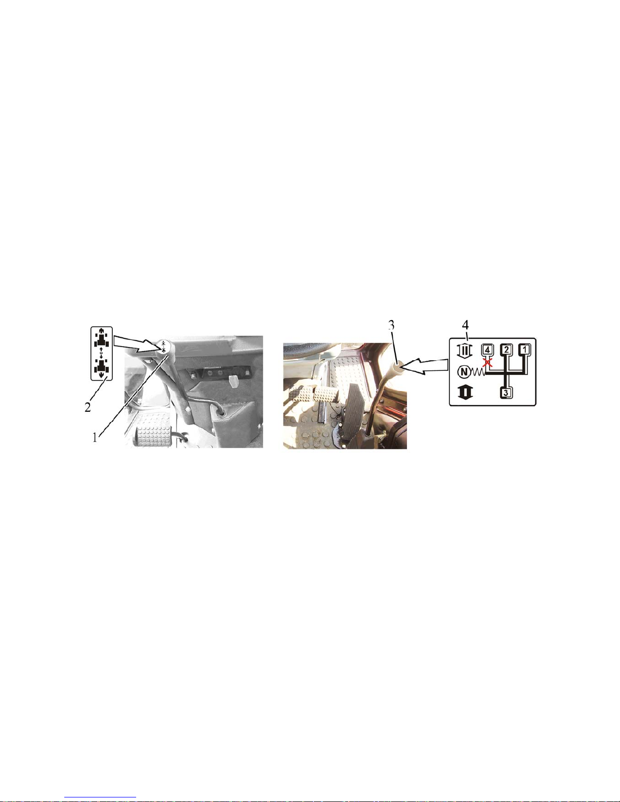
952.5-0000010 OM
45
PEDAL FULLY DEPRESSED. MOVEMENT IN THE FOURTH GEAR IS POSSIBLE ONLY
FORWARD!
The velocity diagram of “BELARUS-952.5” tractor equipped with double-lever GB control and
reverse gear unit on tires of basic configuration is the same as the velocity diagram of
“BELARUS-952.5” tractor equipped with single-lever GB and reverse gear unit shown in figure
2.14.7.
2.14.5 Gears shifting in the transmission with a single-lever GB control and reverse gear
unit
The gears are set by two levers: lever to shift ranges and gears of gearbox 3 (figure 2.14.6)
and control lever of the reverse gear unit 1.
The required ranges, gears and passes of the reverse gear unit (forward motion pass – symbol
"forward", reverse motion pass – symbol "reverse") are set as per the scheme 4 and 2 as it is
shown in Figure 2.14.6.
Gearbox ranges and gears are shifted by one lever 3, first set the range (the I-st or the II-nd),
then set lever in a position «N», so you engage a required gear.
During tractor operation the control lever of the reverse gear unit 1 shall be in switched-on
position (fixed): forward – forward motion pass (“forward”), or reverse – reverse motion pass
(“reverse”). It’s allowed to hold the control lever of the reverse gear unit in a neutral position
(middle, non-fixed) to make easier the engine start at low temperature.
1 – control lever of the reverse gear unit; 2 – diagram of passes shifting of the reverse gear unit;
3 – lever to shift ranges and gears of the GB; 4 – diagram of GB ranges and gears shifting.
Figure 2.14.6 – Gearbox control with single-lever and reverse gear unit
ATTENTION: GEARBOX OF THE TRACTOR EQUIPPED WITH THE REVERSE
GEAR UNIT DOES NOT HAVE A REVERSE GEAR. YOU CHOOSE THE DIRECTION OF
MOVEMENT BY SHIFTING THE CORRESPONDENT PASS OF THE REVERSE GEAR
UNIT!
ATTENTION: YOU CAN ENGAGE THE FOURTH GEAR OF GB ONLY IF THE II
nd
RANGE OF GB AT FORWARD MOTION IS SET!
ATTENTION: SWITCH RANGES AND GEARS OF THE GEARBOX ONLY WITH THE
TRACTOR STOPPED AND THE CLUTCH PEDAL FULLY DEPRESSED. PERFORMING
TRANSPORT OPERATION IT IS PERMITTED TO SHIFT GEARS IN MOTION FROM THE
SECOND TO THE THIRD, FROM THE THIRD TO THE SECOND WITHIN THE I
st
AND THE
II
nd
RANGE, AND ALSO FROM THE SECOND TO THE FOURTH, FROM THE FOURTH TO
THE SECOND, FROM THE THIRD TO THE FOURTH, FROM THE FOURTH TO THE THIRD
WITHIN THE II
nd
RANGE. THE SHIFTING SHALL BE CARRIED OUT AS THE TRACTOR
COASTS AND THE CLUTCH PEDAL FULLY DEPRESSED! ENGAGEMENT AND DISENGAGEMENT OF THE FIRST GEAR, DOWNSHIFTING TO THE FIRST GEAR, ENGAGEMENT AND DISENGAGEMENT OF THE REVERSE GEAR SHALL BE CARRIED OUT ONLY
WITH THE TRACTOR FULLY STOPPED AND WITH THE CLUTCH PEDAL FULLY DEPRESSED.
Page 46
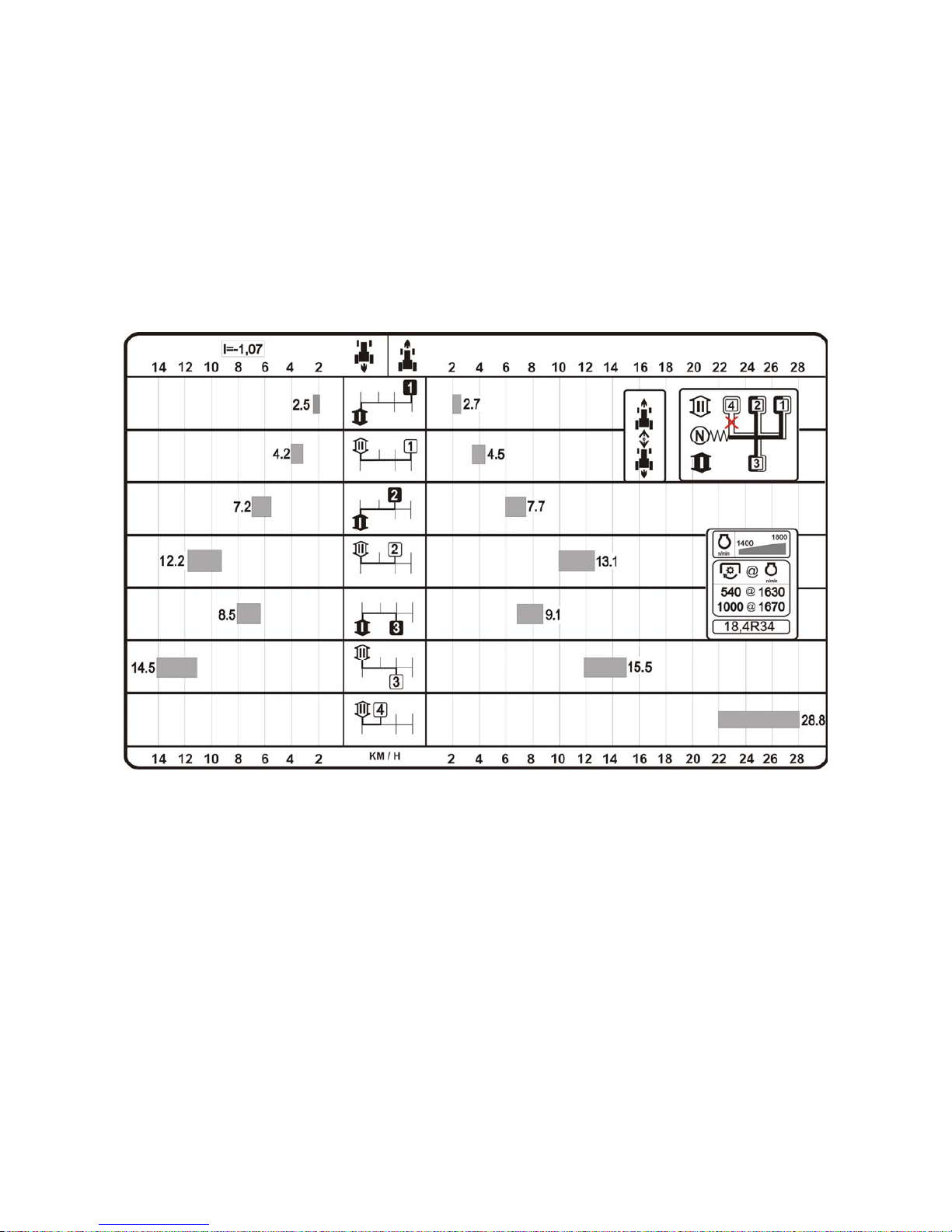
952.5-0000010 OM
46
ATTENTION: THE PASSES SWITCHING OF THE REVERSE GEAR UNIT FROM THE
FORWARD TO THE REVERSE GEAR AND FROM THE REVERSE TO THE FORWARD
GEAR IS CARRIED OUT ON THE FIRST, THE SECOND AND THE THIRD GEAR OF THE
I
st
OR THE IInd RANGE OF THE GB WITH THE TRACTOR STOPPED AND THE CLUTCH
PEDAL FULLY DEPRESSED. MOVEMENT ON THE FOURTH GEAR IS POSSIBLE ONLY
FORWARD!
The velocity diagram table of “BELARUS-952.5” tractor equipped with single-lever GB control
and reverse gear unit on tires of basic configuration is attached to the cab right window and is
shown in Figure 2.14.7.
Figure 2.14.7 – “BELARUS-952.5” tractor velocity diagram with single-lever GB
control and reverse gear unit
Page 47
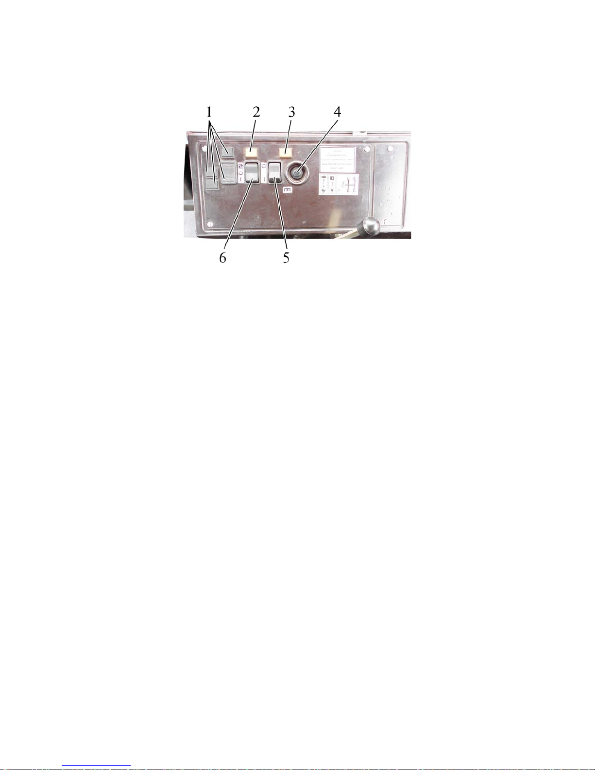
952.5-0000010 OM
47
2.15 Control panel for rear axle DL and rear PTO.
Elements of control panel of rear axle DL and rear PTO are introduced in figure
2.15.1.
Figure 2.15.1 – Control panel of rear axle DL and rear PTO
1 – blind plugs; 2 – rear axle DL pilot lamp; 3 – rear PTO pilot lamp; 4 – rear PTO button
switch; 5- rear PTO control switch; 6– rear axle DL control switch.
Figure 2.15.1 – Control panel for rear axle DL and rear PTO
DL control is carried out by three-position switch 6 (Figure 2.15.1):
- “DL off” – middle fixed position. This position is used during hauling operations on
hard-surface roads;
- “DL is automatically engaged” by pressing the upper part of switch 6. Fixed position. This position is used during operations with significant slipping of rear wheels. In the
automated mode differential is locked during direct motion, and it is unlocked if wheels are
turned through 13° to either side. When left and/or right brake pedal is pressed the differential is unlocked;
- “DL is positively activated” – by pressing the lower part of switch 6. Unfixed
position. This position is used for short-term locking of differential during passage of obstacles. When switch is pressed and held in the lower position, differential is locked. When
switch is released it comes back to the middle position and differential gets unlocked.
When DL is engaged, indicating lamp 2 lights up, which goes out again when DL is
unlocked in an automated mode and with switch 6 is set in the middle position.
ATTENTION: ENGAGE DIFFERENTIAL LOCK WHEN SIGNIFICANT SLIPPING
OCCURS DURING FIELD AND HAULING OPERATIONS!
ATTENTION: DISENGAGE DL WHEN TRACTOR DRIVING SPEED EXCEEDS
13 KM/H. OTHERWISE IT WILL RESULT IN POWER TRAIN OPERATING LIFE REDUCTION AND WILL MAKE IT DIFFICULT TO DRIVE THE TRACTOR. POSITIVE LOCKING
SHALL BE USED ONLY FOR A SHORT PERIOD DURING PASSAGE OF OBSTRUCTIONS IN ROAD.
Note – Rules of rear PTO engagement and disengagement are given in subsection
2.16 “Rear power take-off control”.
Page 48
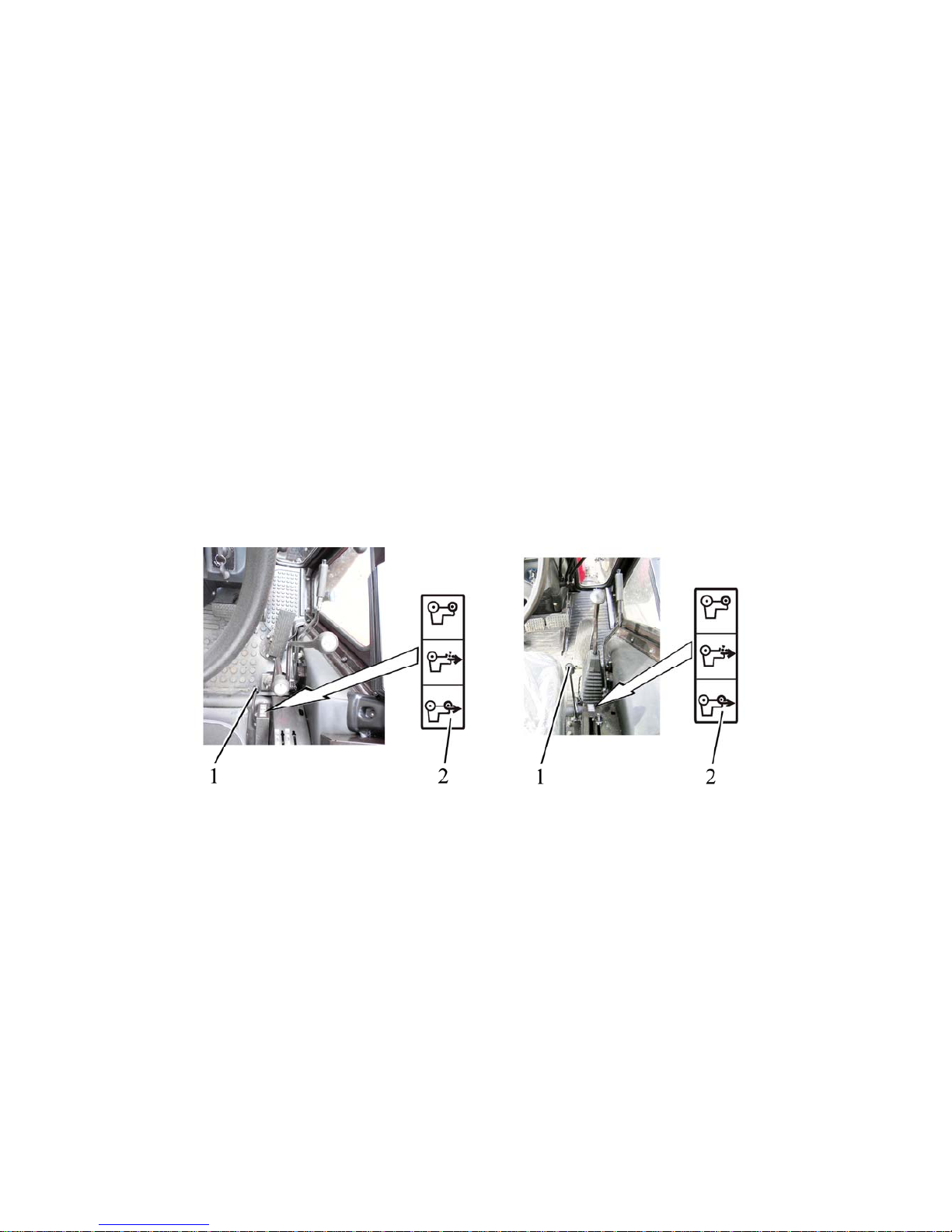
952.5-0000010 OM
48
2.16 FDA drive control
The control switch of the FDA 1 has 3 fixed positions:
- “FDA disengaged” – extreme lower (front) position. This mode is used for transport operations when moving on roads with hard surface;
- «FDA controlled automatically» – middle position. In this mode the FDA is engaged and disengaged with a help of overrunning clutch, depending on the rear wheel skidding. This mode
shall be used at various field works.
- «FDA engaged positively» –extreme upper (rear) position. This mode shall be used only
when the rear wheel skidding is constant or by the reverse movement, when the engagement
of the FDA is necessary.
The modes «FDA controlled automatically» and «FDA engaged positively» shall be used when
the tractor starts the movement.
When the tractor starts the movement, you should switch the FDA drive from the position
«FDA controlled automatically» and «FDA engaged positively» to the position «FDA disengaged» with the clutch pedal fully depressed. If the disengagement of the FDA drive is complicate, don’t switch it by force and do following:
- depress the clutch pedal;
- shift the gear to change the direction of movement to opposite (if the forward gear was
on, you should put the reverse gear and vice versa);
- release slowly the clutch pedal and starting the movement switch the control lever to
the position «FDA disengaged».
а) control lever of the FDA drive b) control lever of the FDA drive
with a double-lever GB control with a single-lever GB control
1 –control lever of the FDA drive; 2 – diagram of the FDA drive control
Figure 2.16.1 – FDA drive control
ATTENTION: OPERATING ON ROADS WITH HARD SURFACE YOU SHOULD DISENGAGE THE FDA DRIVE IN ORDER TO AVOID INCREASED TIRE WEAR OF FRONT
WHEELS!
TRACTOR OPERATION WITH ENGAGED FDA DRIVE WHEN AT A SPEED OF MORE
THAN 13 KM/H IS FORBIDDEN.
ATTENTION: INCORRECT USE OF THE CONTROL MODES OF THE FDA DRIVE CAN
CAUSE BREAKDOWN OF THE FDA AND THE TRANSMISSION COMPONENTS!
Page 49
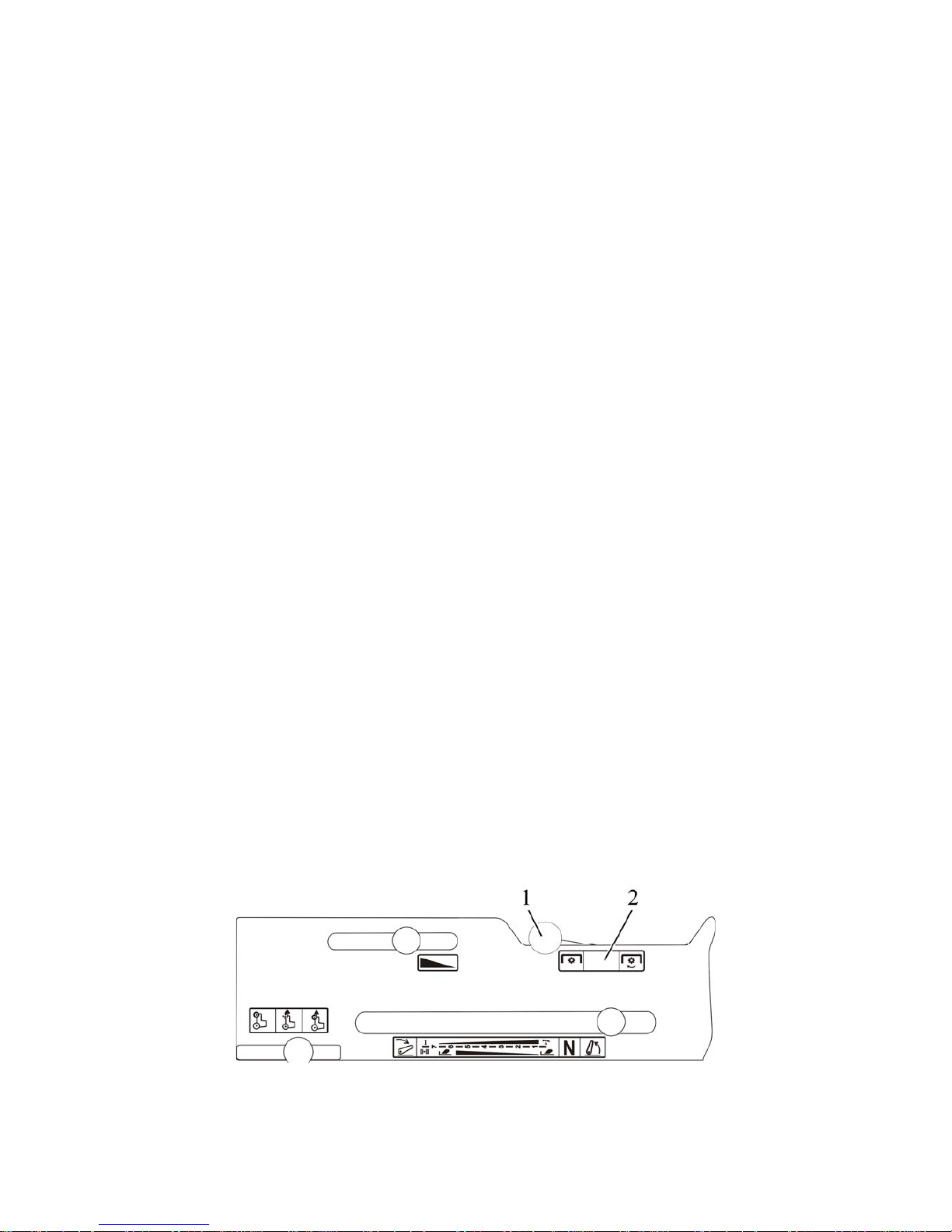
952.5-0000010 OM
49
2.17 Rear power take-off shaft control
2.17.1 Lever shifting rear PTO from continuous drive to ground-speed drive
When lever 44 (Figure 2.1.1) is shifted in the far left position (along tractor
movement) ground-speed drive becomes engaged, and if it is shifted in far right position –
continuous drive becomes engaged, and if it is placed in the middle – “neutral” position.
ATTENTION: ENGAGE GROUND-SPEED DRIVE OF REAR PTO ONLY FROM
NEUTRAL POSITION WITH THE ENGINE IS RUNNING AT LAW GEAR OF THE FIRST
OR SECOND RANGES OF GB ON THE MOVING TRACTOR. OTHERWISE POWER
TRAIN DAMAGES ARE POSSIBLE! SHIFT PTO GROUND-SPEED DRIVE TO A NEUTRAL POSITION IN A SIMILAR WAY!
ATTENTION: SHIFT PTO CONTINUOUS DRIVE FROM NEUTRAL POSITION
ONLY WITH ENGINE SHUT DOWN! SHIFT PTO CONTINUOUS DRIVE TO A NEUTRAL
POSITION IN A SIMILAR WAY!
2.17.2 Rear power take-off shaft engagement
Engagement of rear PTO is possible only when lever 44 (figure 2.1.1) is shifted in
position “ground-speed drive of rear PTO is engaged” or in position “continuous drive of
rear PTO is engaged”. Rear PTO shall not operate in "neutral” position.
On tractors with electro-hydraulically control the rear PTO is engaged by button
switch 5 (figure 2.15.1) and by button switch 4 situated on the control panel for rear axle
and PTO differential lock 41 (figure 2.1.1). The switch has two fixed positions:
- „PTO engaged“- by pressing on the lower part of the switch 5 (figure 2.5.11);
- “PTO disengaged” - by pressing on the upper part of the switch 5.
To engage the PTO do the following:
- press the lower part of the switch 5;
- press short the button switch 4. The pilot lamp 3 goes on and PTO starts to rotate.
To disengage the PTO, press the upper part of the switch 5. The pilot lamp goes out and
PTO stops.
ATTENTION: ON TRACTORS WITH ELECTRO–HYDRAULICALLY CONTROL
THE PTO IS AUTOMATICALLY OFF AT ENGINE STOPPING.
On tractors with mechanical control the rear PTO is engaged by the lever 3 (figure
2.27.1).
The rear PTO engaging lever 3 (figure 2.27.1) has two positions:
- at shifting the lever 3 from extreme front position to extreme rear position the rear
PTO becomes engaged.
- at shifting the lever 3 from extreme rear position to extreme front position the rear
PTO becomes disengaged.
It is recommended to engage and disengage rear PTO with the engine running.
In figure 2.17.1 the rear PTO engaging lever 1 is set into position „rear PTO disengaged“.
1 –rear PTO engaging lever; 2 – instruction plate for rear PTO control
Figure 2.17.1 – Rear PTO engagement diagram with mechanical control
Page 50
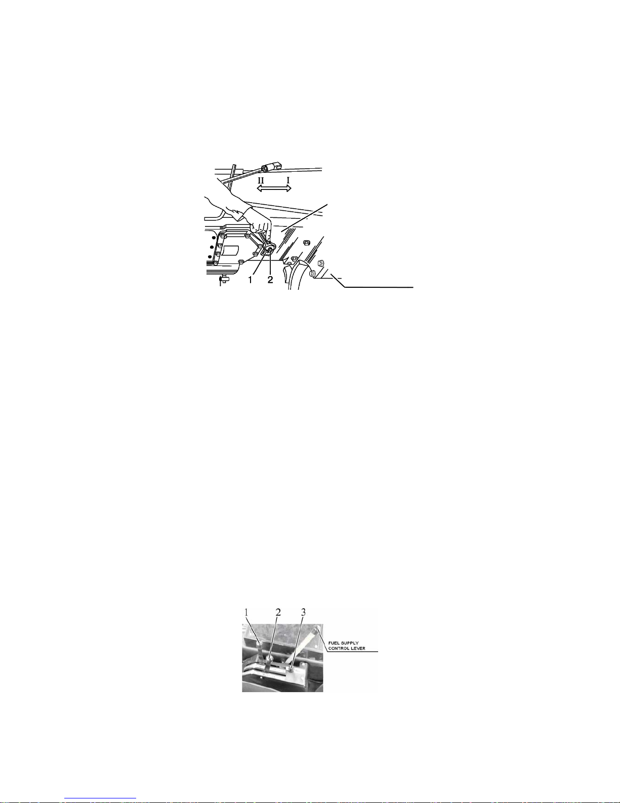
952.5-0000010 OM
50
2.17.3 Two-speed continuous drive of rear PTO switch
The shifter arm of PTO continuous drive 2 (figure 2.17.1) has 2 positions:
I — 540 min
-1)
— full shift position, counterclockwise;
II — 1000 min
-1)
— full shift position clockwise.
In order to select the required PTO shaft rotation speed release the bolt 1 by one
revolution, turn arm 2 into position “I” and “II “ and tighten the bolt 1.
ATTENTION: THE PTO SPEED SHIFTING SHALL BE CARRIED OUT ONLY AT
THE ENGINE NON RUNNING!
1 – bolt; 2 – PTO speed shifter arm
Figure 2.17.2 – PTO rotation speed shifting (transmission bottom view)
2.17.4 Tractor operation without use of rear PTO
When tractor is operated without rear PTO, the arm for shifting of continuous two-speed PTO
drive must be set into position 540 min
-1)
, handle for shifting of rear PTO from continuous to
ground-speed drive - must be set into “neutral” position, button switch for rear PTO control –
must be set into position “PTO off” (on tractors with the rear PTO engagement lever set into
position „PTO off“). Protective cap of rear PTO shaft guard must be mounted.
2.18 Rear lift linkage control with hydraulic lift
2.18.1 RLL control elements with hydraulic lift
RLL is controlled by two levers 1 and 2 (Figure 2.18.1), located in the cab on the
right control console.
Draft control handle 2 is located first after operator’s seat and has following posi-
tions:
- forward most position – maximum soil cultivation depth (“9”);
- rear most position – minimum soil cultivation depth (“1”).
Handle position range 2 is numbered from 1 to 9.
Position 1 control handle has the following positions:
- rear most position (“1”) – RLL transport position;
-forward most position (“9”) – minimum distance between an implement and ground.
Handle 1 position range is numbered from 1 to 9.
Maximum range of lifting of the implement by handle 1 is limited by adjustable
detent 3.
1 – position control handle; 2 – draft control handle; 3 – adjustable detent.
Figure 2.17.1 – RLL control elements
Combined control is carried out by way of implement penetration depth limiting by
handle 1 during operation in the draft control mode.
Clutch housing
Gear box
Page 51

952.5-0000010 OM
51
ATTENTION: IF EACH OF THE HANDLES OR JOYSTICK OF HLL DISTRIBUTOR
ARE SET INTO POSITION „LIFT“ OR „LOWERING“, THE OPERATION OF HYDRAULIC
LIFT IN ALL MODES IS STOPPED!
2.18.2 General information about control rules for RLL with hydraulic lift
Hydraulic lift linkage of your tractor is equipped with hydraulically operated lift and
ensures operation of rear lift linkage in the following modes:
- lift of an attached implement and its lowering under self-weight;
- position control (automated holding of an attached implement at a specified posi-
tion against the tractor);
- Draft control (adjustment of cultivation depth depending on the soil reaction);
- Combined control (adjustment of cultivation depth depending on the soil reaction
with limitation of maximum depth by position control).
Position control allows accurate and sensitive control of position over the ground of
an attached implement such as spraying machine, land smoother and other. Position control can be used with tillage implements on flat fields. Use of position control in the fields
with an uneven surface is limited due to unavoidable vertical travel of the implement when
the tractor is driven along the field undulations.
Draft control is the most appropriate mode of operation with mounted and semimounted implements, working attachment of which are sunk into the soil. The system is
sensitive to changes of drawbar power (caused by change in soil reaction and processing
depth soil) through upper link. Hydraulic system responds to these changes by lifting and
lowering of an implement in order to maintain the intended drawbar power at a fixed level.
The system responds to compressive force and extension force in the upper link i. e. it is
double action system.
Combined control – if due to variations in soil density draft control does not allow
reaching of constant processing depth, the predetermined depth should be limited by
means of position control handle.
Position control shall be carried out as follows:
- set handle 2 (figure 2.18.1) of draft control to the forward most position in the
direction of tractor travel;
- set the required height of the implement above the ground by means of handle 1
of position control.
Number “1” corresponds to transport position of RLL, and number “9” – to the minimum height of the implement above the ground. In case it is necessary to limit the maximum lifting range (for example, because of possibility of rear PTO shaft parts damage), set
the maximum lifting range by handle 1 and bring an adjustable detent 3 to it.
Draft control shall be carried out as follows:
- set handle 2 (of draft control to the forward most position in the direction of tractor
travel (number “9” of the control desk);
- connect the implement with RLL by means of handle 1 of the position control;
- after entering the groove shift handle 1 to the forward most position and by means
of handle 2 set the required soil processing depth;
- while leaving and entering the grove again (during tilling) use only handle 1 of po-
sition control, and do not touch handle 2 of the draft control.
If due to variations in soil density draft control does not allow reaching of constant
processing depth, the predetermined depth should be limited by means of position control
handle 1 (combined control mode), keeping in mind the corresponding number on the control desk.
When combined control is used the degree to which signals of the two sensors
(force sensor and position sensor) are combined is controlled by handles 1 and 2.
ATTENTION: BEFORE LEAVING THE TRACTOR FOR ANY PERIOD OF TIME
YOU MUST GROUND THE IMPLEMENT!
Note – Rules for control of draft control unit with is optional mounted on tractoer instead
of hydraulic lift are given in subsection 2.27 “Controls of the tractor equipped with RLL with
draft control unit, mechanical rear axle DL control and rear PTO”.
Page 52
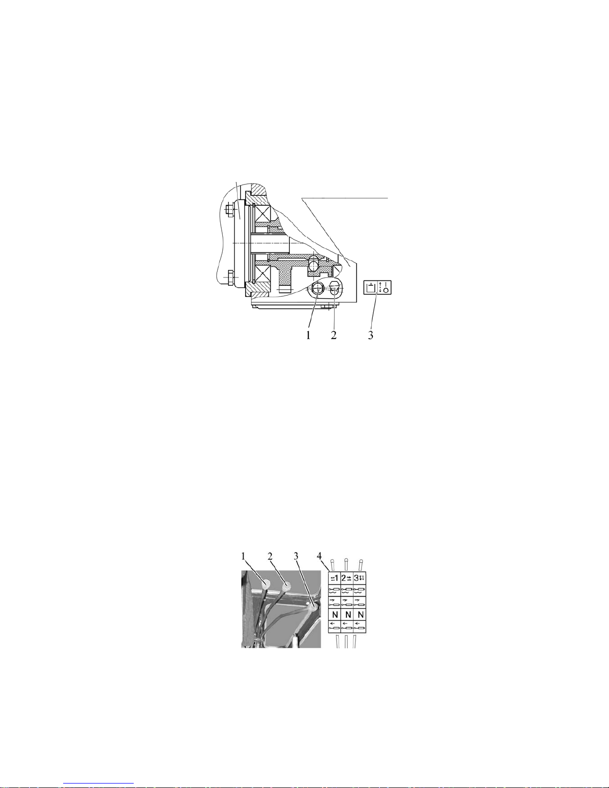
952.5-0000010 OM
52
2.19 HLL pump control
The HLL pump switching shaft 1 (figure 2.19.1) has two positions:
- “shaft on” – the shaft 1 is turned clockwise against the stop;
- “shaft off” – the shaft 1 is turned contraclockwise against the stop.
Before turning the shaft 1 to any of 2 two positions, loosen a bolt 2 by 1,5…2 revolutions and turn the shaft 1 together with a locking plate. Tighten the bolt 2.
The HLL pump activation diagram is given in fig. 2.19.1, as well as in the instruction
shield on the lower part of the cab front wall.
1 – HLL pump switching shaft; 2 – bolt; 3 – HLL pump activation diagram.
Figure 2.19.1 – HLL pump control
Note – The figure 2.19.1 shows the position “HLL pump on”.
ATTENTION: THE PUMP SHALL BE TURNED ON AND OFF ONLY WITH THE
MIN. IDLE SPEED OF THE ENGINE!
In case failures in HLL occur that lead to oil leakage out of the hydraulic lift linkage,
the pump shall be turned off when moving the tractor to repair facilities.
2.20 Hydraulic lift linkage distribution valve sections (remote cylinders) control
2.20.1 Remote hydraulic cylinders with distribution valve RP70-1221 (RP70-1221 C) or
RP70-1221.1 (RP70-1221.1 C) or RS213Mita (RS213Belarus) installed control by means of
levers.
Note: symbols identifying distribution valves are shown in brackets for tractors which
are optionally equipped with draft control unit instead of hydraulically operated lift.
1, 2, 3, - hydraulic lift linkage distribution valve (remote cylinders) control levers; 4 - instruction plate containing distribution valve RP70-1221 (RP70-1221 C) or RP70-1221.1
(RP70-1221.1 C) or RS213Mita (RS213Belarus) control diagram.
Figure 2.20.1: Remote hydraulic cylinders with distribution valve RP70-1221 (RP701221 C) or RP70-1221.1 (RP70-1221.1 C) or RS213Mita (RS213Belarus) installed control by
means of levers.
HLL pump
Hydraulic system casing
HLL pump
Page 53
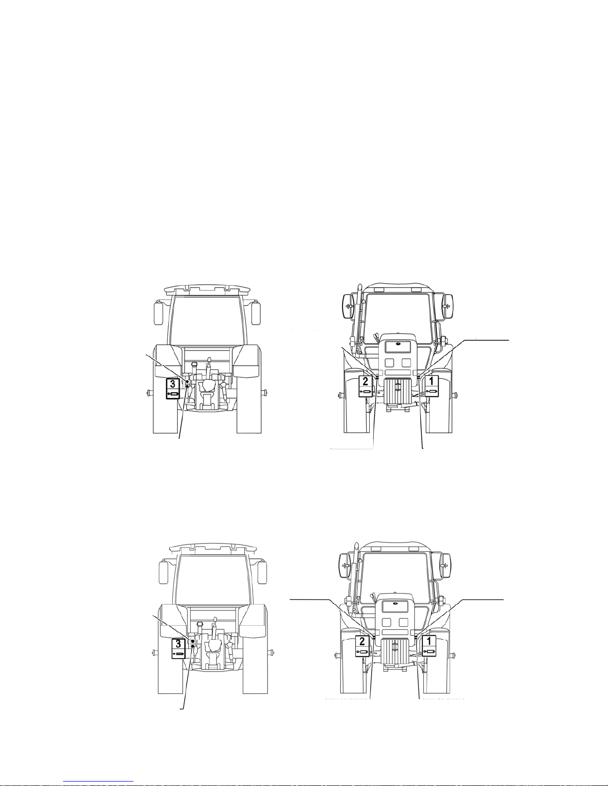
952.5-0000010 OM
53
Each of the three remote hydraulic control levers 1, 2, 3 (Figure 2.20.1) of distribution valve RP70-1221 (RP70-1221 C) or RP70-1221.1 (RP70-1221.1 C) or RS213Mita
(RS213Belarus)
has four positions:
"Float" – uppermost fixed position;
“Forced lowering” – middle upper non-fixed position between “Float” and “Neutral”
positions. In “Forced lowering” position with the engine running the lever shall be kept in
hand, because after releasing the handle it returns to “Neutral” position;
“Neutral” – bottom fixed middle position;
“Lift” – lowermost non-fixed position with distribution valve RP70-1221 (RP70-1221
TC) or
RS213Mita (RS213Belarus) installed. In “Lift” position with the engine running the
lever shall be kept in hand, because after releasing the handle it returns to “Neutral” position (in case if distribution valve RP70-1221.1 (RP70-1221.1 C) is installed, the lever 2 is
fixed without automatic return into “Neutral” position. To avoid overheating of the hydraulic
system and early breakdown of the pump and other units of the hydraulic lift linkage, do
not forget to set the valve spool control lever into “Neutral” position after fulfillment of the
operation).
Diagram of distribution valve RP70-1221 (RP70-1221 C) or RP70-1221.1 (RP70-
1221.1 C), RP70-622, RP70-622.1
outputs positioning and connection to the external con-
sumers on tractors “BELARUS-952.5” is presented in figure 2.20.2.
Figure 2.20.2 – Diagram of distribution valve RP70-1221 (RP70-1221 C), RP70-
1221.1 (RP70-1221.1 C), RP70-622 (RP70-1221TC)
1 outputs positioning and connection to
the external consumers.
Diagram of distribution valve RS213Mita (
RS213Belarus) outputs positioning and
connection to the external consumers on tractors “BELARUS-952.5” is presented on Figure 2.20.3.
Figure 2.20.3. – Diagram of distribution valve RS213Mita (RS213Belarus) outputs po-
sitioning and connection to the external consumers.
Lowering
Lowering
Lowering
Lift
Lift
Lift
Lift
Lowering
Lowerin
g
Lowering
Page 54
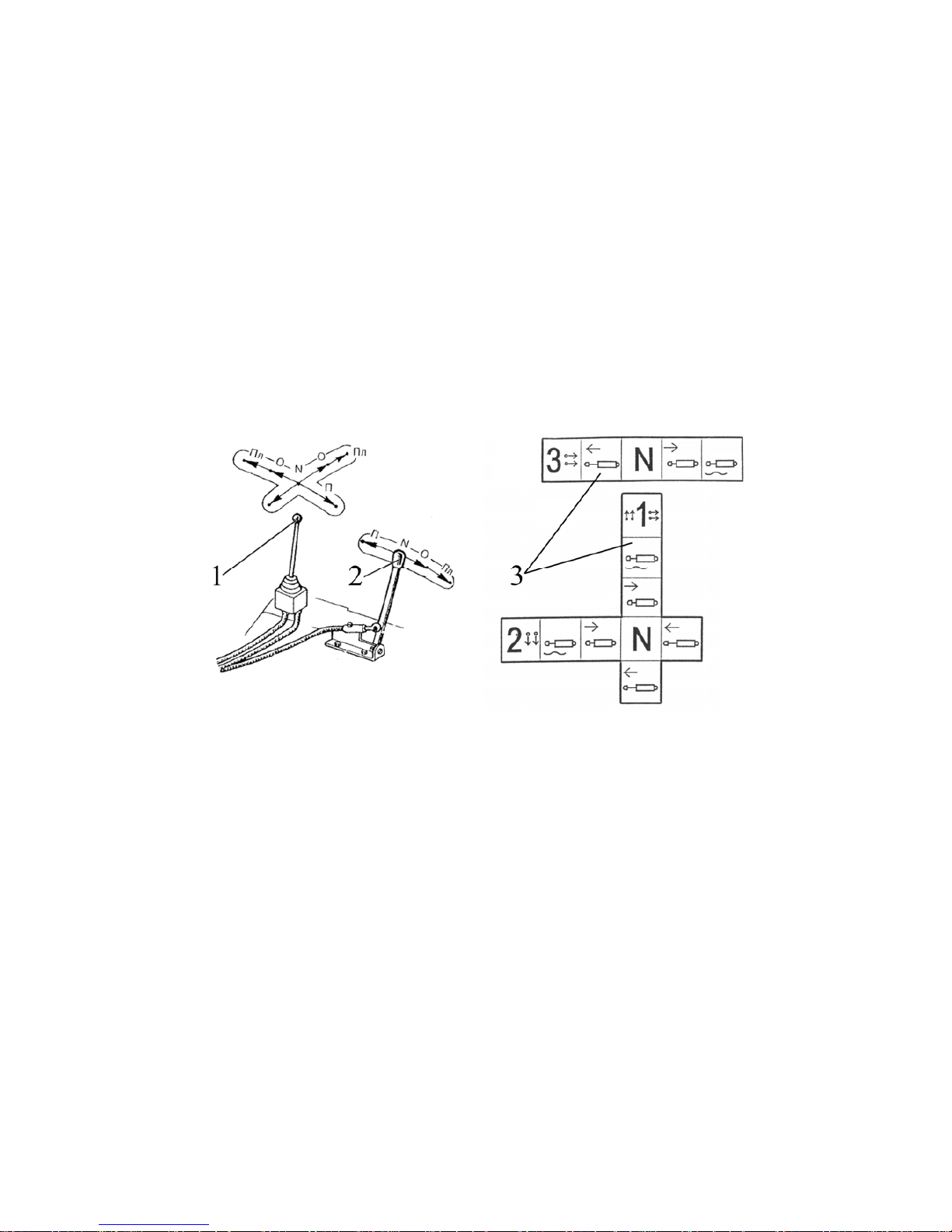
952.5-0000010 OM
54
2.20.2 Remote hydraulic cylinders with distribution valve RP70-622 or (RP70-
1221TC)
installed control by means of joystick and lever
Note: symbols identifying distribution valves are shown in brackets for tractors which
are optionally equipped with draft control unit instead of hydraulically operated lift.
When distribution valve RP70-622 or (RP70-1221TC) are installed on the tractor the
remote control of the distribution valve spool is possible, which is performed by means of
joystick 1 (Figure 2.20.4) and lever 2 with two-way motion ropes. Joystick and lever are installed on the right control console in tractor cab instead of hydraulic system distribution
valve outputs control levers.
Joystick 1 is designed for control of the two distribution valve spools (sections):
- when joystick lever 1 is moved lengthwise the spool connected to the left side hy-
draulic outputs is controlled.
- when joystick lever 1 is moved in cross direction the spool connected to the right
side hydraulic outputs is controlled.
The lever 2 may be shifted only lengthwise and is controlled by the middle spool,
connected to the rear left hydraulic system outputs.
1- joystick; 2 - lever; 3 - instruction plates for joystick and lever control.
Figure 2.20.4 Control by means of joystick and lever of remote hydraulic cylinders
with distribution valve RP70-622
(RP70-1221TC) installed.
Diagram of distribution valve RP70-622 (RP70-1221TC) outputs positioning and connection to external consumers on the tractors "BELARUS-952.5" is shown in figure 2.20.2.
Page 55
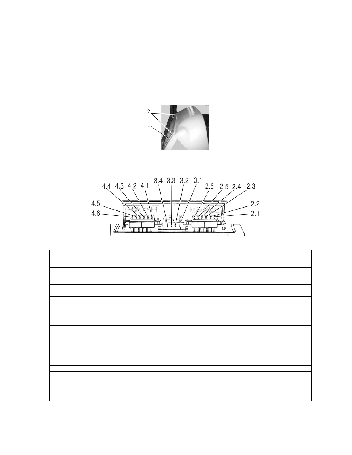
952.5-0000010 OM
55
2.21 Cutout fuses
2.21.1 General information
Cutout fuses are intended for protection of electrical lines against overloads and
short circuit.
WARNING: TO AVOID BURNING OF TRACTOR WIRING NEVER USE FUSES
WITH CURRENT RATING HIGHER THAN RATING SPECIFIED IN THIS SECTION. IF A
FUSE OFTEN BURNS OUT, FIND OUT THE CAUSE AND ELIMINATE THE FAULT!
2.21.2 Fuses for electrical equipment system
Three blocks of cutout fuses are built into the instrument board. To access the cutout fuses do two
screws 2 out (Figure 2.21.1) and open the cover of the instrument board 1.
1 – cover of instrument board; 2 – screw.
Figure 2.21.1 – Arrangement of fuse blocks in the instrument board
Fuses, located in the instrument board, are shown in fig. 2.21.2.
Figure 2.21.2 – Arrangement of fuses in the instrument board
Figure 2.5 – Assignment of fuses in the instument board
Number as per
figure 2.21.2
Rated current Name of protected circuit
Right fuse block
2.1 15А Power to turn flasher, power to heating plug controller
2.2 7,5 А Gauges, pilot lamps unit, speed sensors, fuel sensor, relay coil of fuel filter heater, audible
warning (buzzer)
2.3 7,5А Lower beam of the right road light
2.4 7,5 А Lower beam of the left road light
2.5 15А Parking lights of the right side, terminal (5) of trailer socket, instrument illumination
2.6 7,5 Parking light of the left side, terminal (7) of trailer socket, number-plate light
Central fuse block
3.1 25 А Power to fan-heater or conditioner
3.2 25 А Power to instruments, to side console before engine start-up, power to fuse 2.1, power
to consumers of starter and instruments switch
3.3 25 А Power to central light switch, to electronic control system of FDA and automatic DL (after en-
gine start-up), fan-heater control
3.4 25 А Front working lights, beacon, working lights on handgrips
Left fuse block
4.1 25 А Road lights upper beam, indicator lamp of upper beam activation
4.2 15 А Audible beep
4.3 25 А Front and rear window wipers, window washer
4.4 15 А Warning light
4.5 15 А Road-train lights, rear working lights, cab light
4.6 15 А Braking lights, terminal (6) and terminal (8) of trailer socket
Page 56
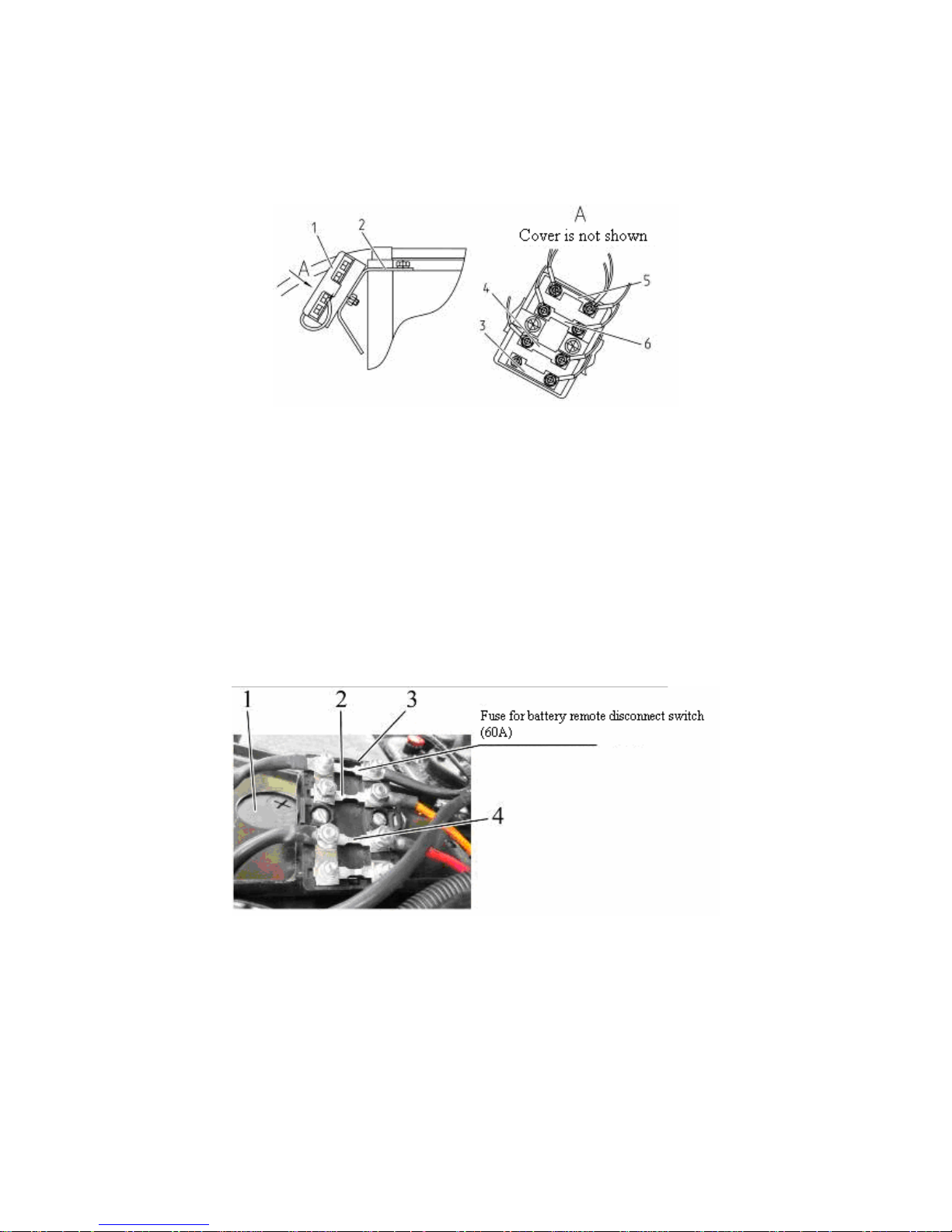
952.5-0000010 OM
56
Apart from the fuses, located in the instrument board and shown in fig. 2.21.2 the
on-board circuit of “BELARUS-952.5” tractor has an additional block of fuses 1, located on
the bracket 2 (Figure 2.21.3) of the HLL oil tank body and intended to protect power circuits of electrical equipment.
1 – fuse block, 2 – bracket; 3 – 80А fuse (power to on-board circuit before start-up,
battery charging, positive side to starter relay leads, power to fuel filter heater); 4 – 80А
fuse (power to heating plugs); 5 – 60А fuse (power to instrument board); 6 – 60А fuse
(power to instrument board).
Figure 2.21.3 – Fuses, located on HLL oil tank body
Location of the fuse for a battery remote disconnect switch and a stereo-recorder is
shown in figure 2.21.4. Besides a suspended 25A fuse is installed in the circuit of the battery remote disconnect switch.
2.21.3 Fuse for engine electronic control system
The location of the fuses for the EECS 2 and 4 in the fuse block 3 is shown in fig. 2.21.4
(the fuse block 3 is located above the storage battery 1).
1 – storage battery; 2 – 60A fuse for EECS constant powering (at any position of the
battery disconnect switch); 3 – fuse block; 4 – 80A fuse for EECS powering when the storage battery switch is in turned on position.
Figure 2.21.4 – Installation place of fuse for EECS powering
Page 57
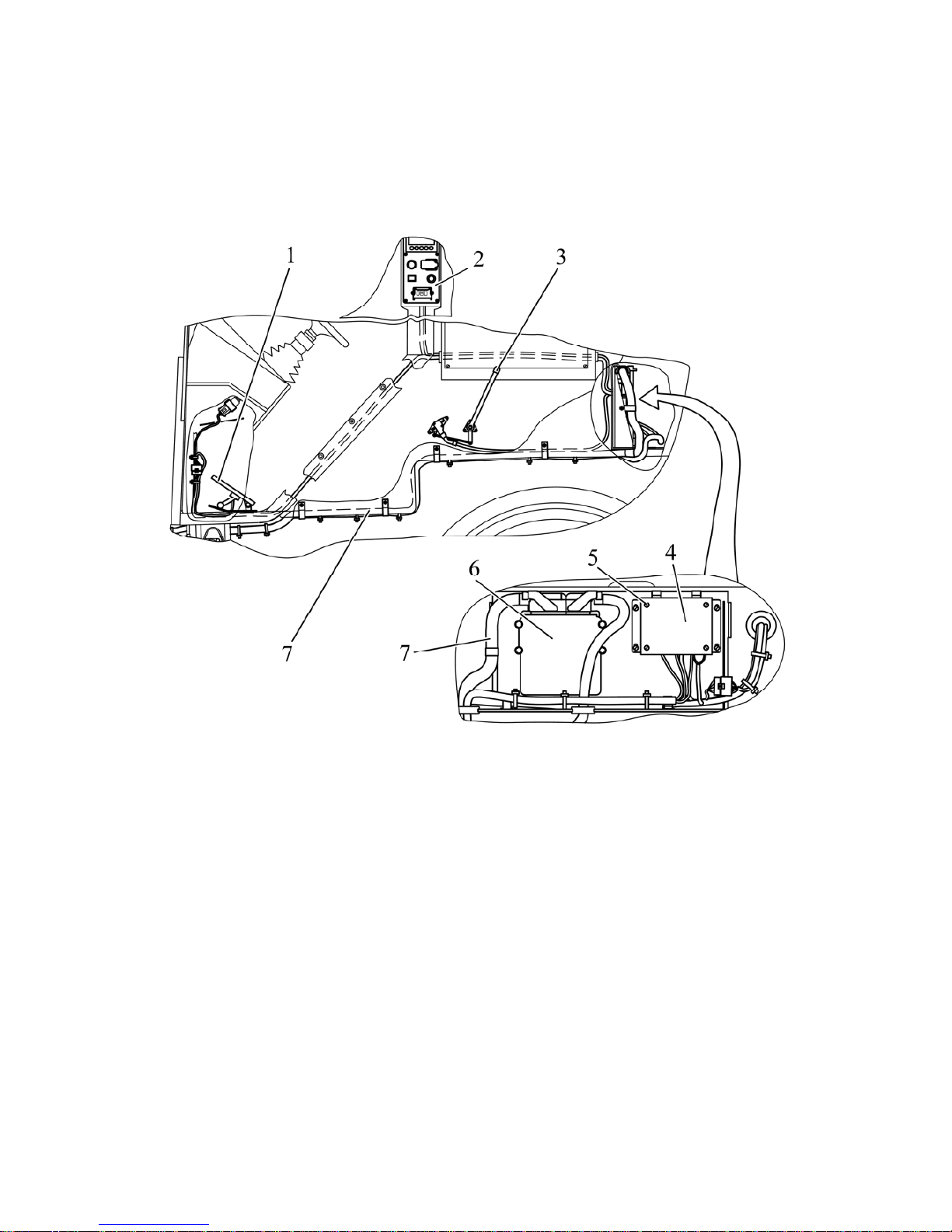
952.5-0000010 OM
57
The other fuses for EECS are mounted in the protection and switching unit. switching and protection unit.
The protection and switching unit (PASU) of 1000 SCR series is intended to distribute power supply to tractor electronic control systems and to protect their electrical circuits
against short circuit and current overload.
The PASU is installed in the rear part of the cab, at a special compartment behind
the driver seat, as shown in figure 2.21.5.
1 – electronic foot pedal to control fuel feed; 2 – console of engine control system; 3
– electronic handle to control fuel feed; 4 – protection and switching unit; 5 – screw; 6 –
engine electronic control unit; 7 –connection bundles.
Figure 2.21.5 – Arrangement of EECS components in the cab
To access the PASU it is required to do four bolts out and open the cover of the
special compartment. Then to access the relay and fuses of the PASU do four screws 5
out (Figure 2.21.5) and take the iron cover off.
The block includes ten fuses 1(Figure 2.21.6) (F1…F10), seven electromagnetic relays 4 (K1…K7), commutating power supply for consumers. Each fuse has got warning
LEDs of red color mounted on the front panel nearby which are intended to warn that the
corresponding fuse blew out. Besides there are warning LEDs of yellow color 2 and 3. The
LED 2 indicates continuous power supply to PASU, regardless of the position of the battery switch. The LED 3 indicates presence of continuous power, supplied to PASU only
with the battery switch turned on.
The arrangement diagram of fuses, relays and other components of PASU is given
in figure 2.21.6.
Page 58
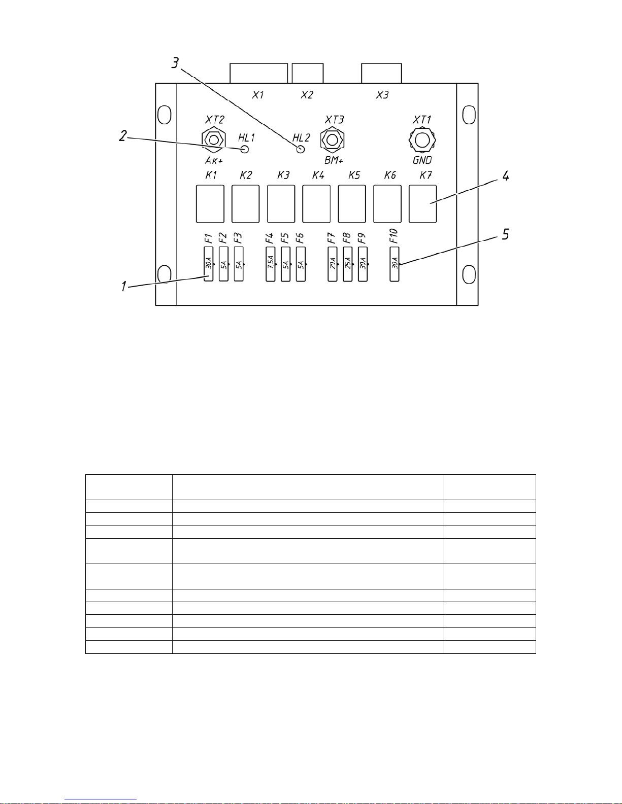
952.5-0000010 OM
58
1 – fuse; 2, 3 – warning LED of yellow color; 4 – electromagnetic relay; 5 – warning
LED of red color.
Figure 2.21.6 – Protection and switching unit
Information on assignment and rating of fuses and on assignment of relays is given
in Tables 2.6 and 2.7 accordingly.
Electric connection of bundles of electronic control systems to connectors X1…X3
(Figure 2.21.6) and to leads XT1…XT3 of the PASU shall be carried out in accordance
with table 2.8.
Table 2.6 – Assignment of PASU fuses
Fuse identifi-
cation
Assignment of fuse
(protected electric circuit)
Fuse rating
F1 Power to EECS (terminal 30) 30А
F2 Power to heavy-duty relay (not used) 5А
F3 Power to information display 5А
F4
Protection of circuit of power supply after the instruments are on (terminal 15)
7,5А
F5
Protection starter actuation control circuit (terminal
50) (not used)
5А
F6 Power to testing equipment 5А
F7 Power to cigar lighter 20А
F8 Power to electrical socket 25А
F9 Power to SCR heater 30А
F10 Protection of heater “ground” circuit 30А
Page 59

952.5-0000010 OM
59
Table 2.7 – Assignment of PASU relay
Relay identifi-
cation
Assignment of relay
К1
Relay of power supply to engine electronic control unit EDC (not
used)
К2 Relay of power supply after instruments are turned on
К3 Common power supply to SCR heaters
К7 Power supply to SCR heaters
К4 Activation of a heater for SCR charging hose
К5 Activation of a heater for SCR drain hose
К6 Activation of a heater for SCR intake hose
К7 Activation of a heater of SCR supply module
Table 2.8 – Connection of wire bundles to PASU
Connector
(contact)
Component being connected
Х1 Bundle of engine electronic control system
Х2
Bundle of electric socket and heater, located on the engine control
panel
Х3 SCR bundle
ХТ1 Black wire or with “Ч” mark, with tag M8 – PASU ground
ХТ2
Yellow wire or with “Ж” mark, with tag M5 – constant DC supply to
PASU (+12V) regardless of battery switch position
ХТ3
Red wire or with “K” mark, with tag M6 – power to PASU (+12V),
supplied to PASU only with the battery switch turned on
Page 60
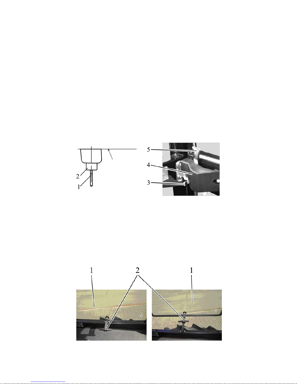
952.5-0000010 OM
60
2.22 Cab locks and handles
2.22.1 Cab door locks
Left and right doors of tractor cab are secured inside with locks 4 (figure 2.22.1).
The lever 5 serves to open the left and right cab doors from inside the cab. Moving the
lever 5 backward unlocks the door. The locks of the right and left doors can be blocked
from inside the cab. To block the lock from inside the cab it is needed to shift the detent 3
into the lower extreme position.
With the lock 4 unblocked the left door is opened from outside by pushing the button
2 of the handle.
The lock of the cab left door can be opened and closed from outside. To close it
from outside do the following:
- insert a key 1 into the hole of the cylinder mechanism, which is located in the button 2;
- without pushing the button 2 turn the key into position “closed”.
To open the left door lock outside the cab, it is necessary to insert the key 1 into the
hole of the cylinder mechanism, which is located in the button 2 and without pushing the
button 2 turn the key into position “opened”, then press the button 2.
1 – key; 2 – button; 3 – detent, 4 – lock; 5 – lever.
Figure 2.22.1 – Cab door lock
2.22.2 Left-side window opening
To open the left-side window 1 (Figure 2.22.2) it is required to take a handle 2 up and
push to secure the side window 1 in an opened position.
To close the left-side window 1 take the handle 2 up and pull to secure the side window
1 in a closed position.
а) window closed b) window opened
1 – left-side window; 2 –.handle.
Figure 2.22.2 – Side window opening
Door
Page 61
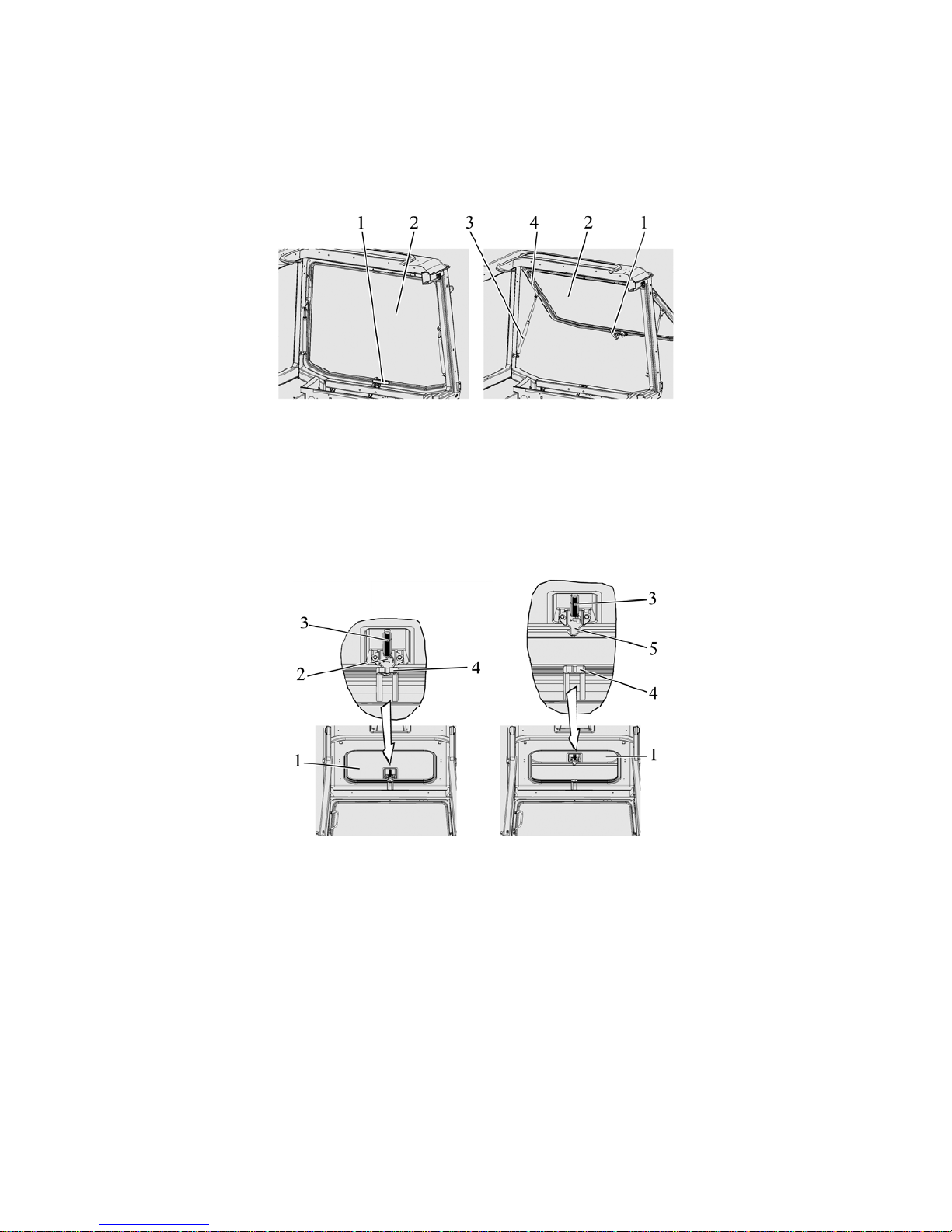
952.5-0000010 OM
61
2.22.3 Rear window opening
To open the rear window 2 (figure 2.22.3) turn a handle 1 upwards (counterclockwise) and push rear window away. Under the influence of airlifts 3 it will take tilt position.
To close the rear window pull the handgrip 4 on until the window is fixed in window
aperture, turn handle 1 clockwise until handle detent planes into coincidence with bracket
forming.
.
а) rear window closed b) rear window opened
1 – handle; 2 – rear window; 3 – airlift; 4 – hand grip.
Figure 2.22.3 – Rear window opening
2.22.4 Cab roof opening
To open the roof 1 (figure 2.22.4) pull the hand grip 3 down, push detent 2 up and
pressing it push hand grip 3 with the roof 1 up, until the roof is fixed in open position.
To close the roof 1 pull the hand grip 3 down until the roof 1 is fixed in a close position (the latch 5 shall be fixed in the bracket 4).
а) roof closed b) roof opened
1 – roof; 2 – detent; 3 – hand grip; 4 – bracket; 5 – latch.
Figure 2.22.4 – Cab roof opening
2.22.5 Cab emergency exits
The cab has the following emergency exits:
- doors – left and right;
- rear window;
- roof.
- left-side window.
2.23 Seat and its adjustments
2.23.1 General information
The seat has a mechanical suspension, consisting of two spiral torsion springs and
a gas charged shock absorber of bidirectional operation. A “scissors”-type guiding mechanism ensures a strictly vertical movement of the seat. A dynamic seat stroke is 100 mm.
Page 62
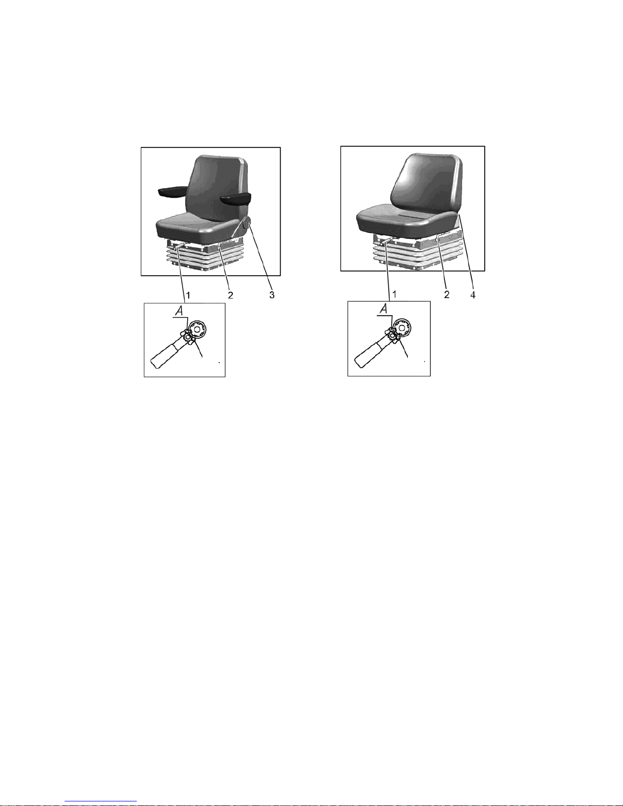
952.5-0000010 OM
62
ATTENTION: BEFORE STARTING TO OPERATE THE TRACTOR ADJUST THE
SEAT TO REACH THE MOST COMFORTABLE POSITION. CARRY OUT ALL ADJUSTMENTS WHEN STAYING IN THE SEAT! THE SEAT IS CONSIDERED CORRECTLY
ADJUSTED ACCORDING TO THE MASS IF IT MOVES HALF OF THE STROKE UNDER
THE OPERATOR'S WEIGHT (THE SUSPENSION STROKE IS 100 MM)!
2.23.2 Adjustments of BELARUS seat
а) Seat BELARUS 80-6800010» b) Seat BELARUS 80В-6800000»
1 – handle to adjust according to the weight; 2 – handle for longitudinal adjustment;
3 – hand wheel to adjust the backrest tilt. 4 – handle to adjust the backrest
Figure 2.23.1 BELARUS seat adjustments
The seat “BELARUS” has the following adjustments:
- adjustment according to the operator's weight. It is carried out by means of a handle 1
(figure 2.23.1) within the range from 50 to 120 kg. To adjust the seat for a bigger weight it is
required to shift the pawl of the lever 1 into position “A” and tighten the springs with a reciprocal movement. To adjust the seat for a smaller weight it is required to shift the pawl into position “B” and release the springs with a reciprocal movement.
- longitudinal adjustment. It is carried out by means of a handle 2 within the range of ±
80 mm from the middle position. To move the seat forward-backward it is required to pull the
handle 2 up, move the seat and then release the handle. The seat will automatically get locked
in a required position.
- adjustment of the backrest tilt angle:
a) For the seat “BELARUS 80-6800010” the backrest tilt angle is adjusted by means
of a hand wheel 3 within the range from minus 15° to plus 20°. To increase the backrest tilt
angle it is necessary to turn the hand wheel clockwise, to decrease it – counterclockwise.
b) For the seat “BELARUS 80B-6800000” the backrest tilt angle is adjusted by
means of handle 4 within the range from plus 5° to plus 25°. To change backrest tilt angle it
is required to pull the handle 4 up to the stop, move the backrest to the necessary direction
to achieve the required angle and then release the handle. The seat will get locked in a required position.
- height adjustment is carried out within the range of ± 30 mm from the middle position. The
seat has three height positions: “lower”, “middle” and “upper”. To move the seat from the “lower” position to the “middle” position or from the “middle” position to the “upper” one it is required to lift the
seat up smoothly till the arresting stop goes off (a specific click is heard). To move the seat from the
“upper” position into the “lower” one it is necessary to lift the seat up against the stop with an abrupt
movement and let it down. It is impossible to move the seat from the “middle” position to the “lower”
one.
B
B
Page 63
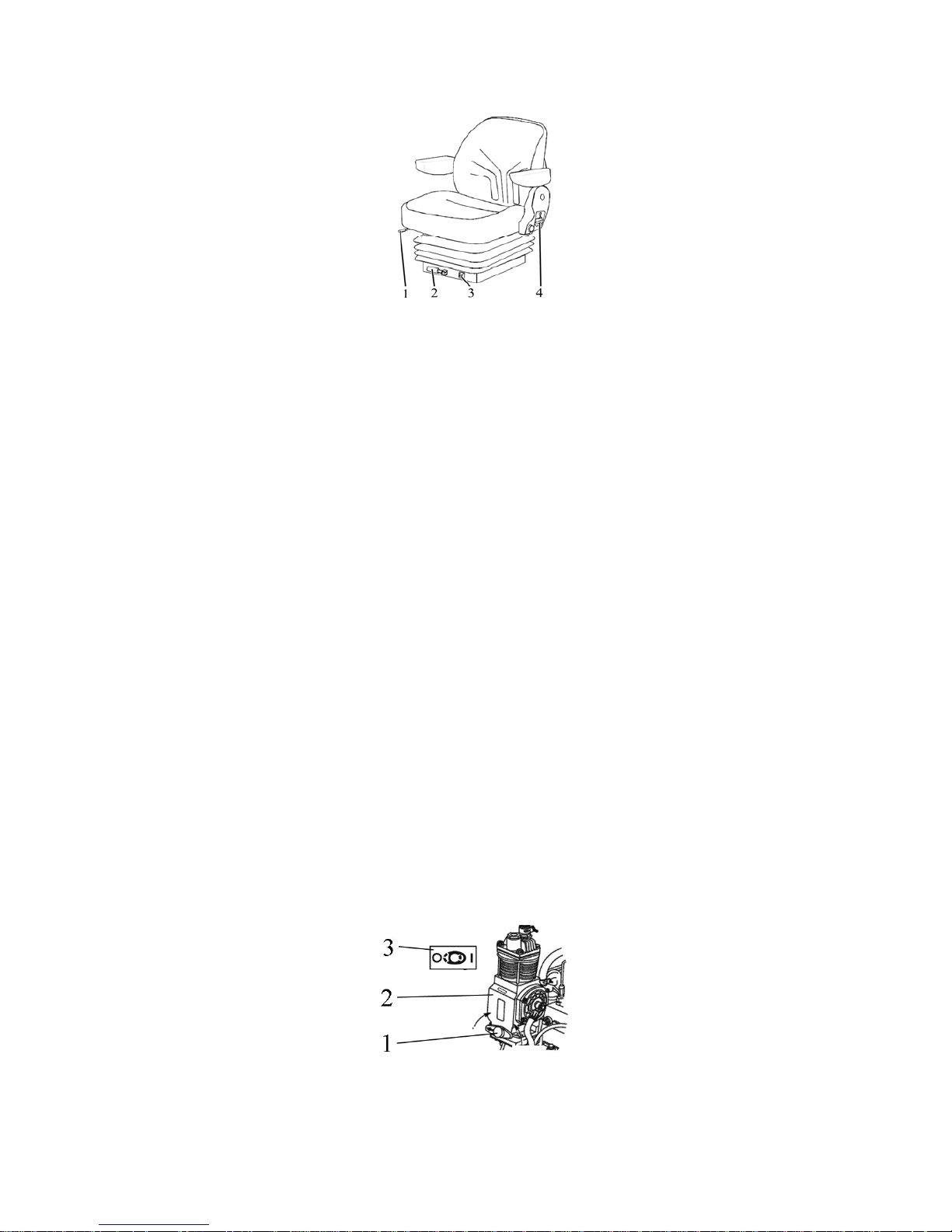
952.5-0000010 OM
63
2.23.3 Adjustments of Grammer seat
Your tractor can be equipped upon request with Grammer seat (Figure 2.23.2).
1 – handle for longitudinal adjustment; 2 – handle to adjust according to the weight;
3 – indicator of seat adjustment according to the weight; 4 – handle to adjust the backrest tilt.
Figure 2.23.2 – Grammer seat adjustments
The Grammer seat has the following adjustments:
- adjustment according to the operator's weight. It is carried out by means of a handle 2
(figure 2.23.2) within the range from 50 to 130 kg with weight indication in 10 kg. To
adjust the seat for a bigger weight it is required to turn the handle clockwise, to adjust the seat for a smaller weight – turn it contraclockwise.
- longitudinal adjustment. It is carried out by means of a handle 1 within the range of ± 75
mm from the middle position. To move the seat forward-backward it is required to
pull the handle 2 up, move the seat and then release the handle. The seat will
automatically get fixed in a required position.
- adjustment of the backrest tilt angle. The backrest tilt angle is adjusted by means of a
lever 4 within the range from minus 10° to plus 35°. To change the backrest tilt angle
it is required to pull the handle 4 up to the stop, move the backrest to the necessary direction to achieve the required angle and then release the lever. The seat will get
locked in a required position.
- height adjustment. It is carried out within the range of ± 30 mm from the middle position.
The seat has three height positions: “lower”, “middle” and “upper”. To move the seat
from the “lower” position to the “middle” position or from the “middle” position to the
“upper” one it is required to lift the seat up smoothly till the arresting stop goes off (a
specific click is heard). To move the seat from the “upper” position into the “lower”
one it is necessary to lift the seat up against the stop with an abrupt movement and
let it down. It is impossible to move the seat from the “middle” position to the “lower”
one.
2.24 Controlling pneumatic system compressor
Handle to turn the pneumatic system compressor 1 on (figure 2.24.1) has two positions:
• left (the arrow on the handle is directed forward as viewed along tractor movement) –
“compressor off”,
• right (the arrow on the handle is directed backward to tractor cab) – “compressor on”.
ATTENTION: TURN THE PNEUMATIC SYSTEM COMPRESSOR ON AND OFF ONLY WITH THE ENGINE NOT RUNNING OR WITH MIN. IDLE SPEED OF THE ENGINE!
1 – handle to turn the pneumatic system compressor on; 2 – pneumatic system compres-
sor; 3 – diagram of pneumatic system compressor control.
Figure 2.24.1 – Pneumatic system compressor control
Note – The figure 2.24.1 shows position “pneumatic system compressor off”.
ON
OFF
Page 64
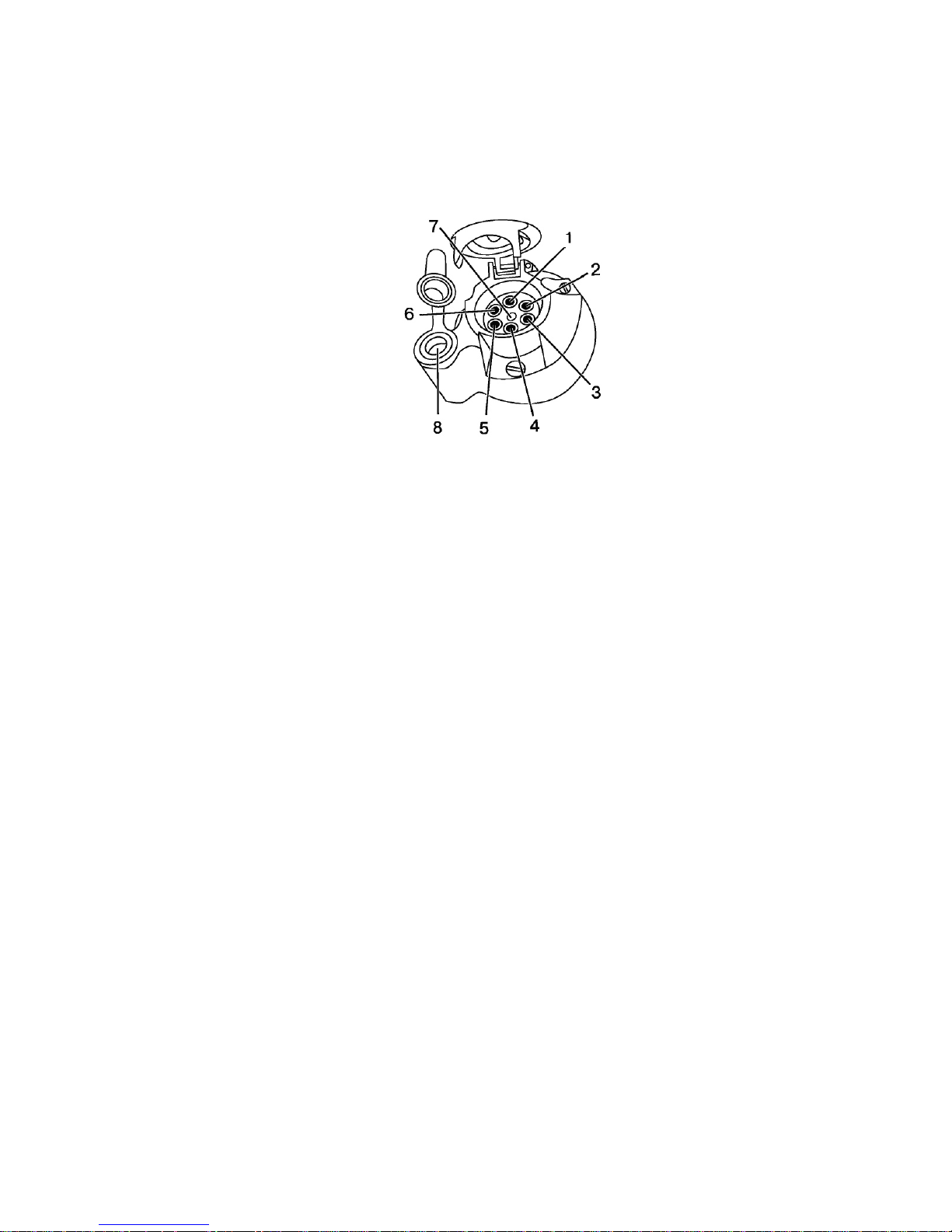
952.5-0000010 OM
64
2.25 Connector elements of the electrical equipment
2.25.1 Socket to connect coupled agricultural equipment
A standard seven-pin socket with an additional receiver to connect a portable lamp (figure
2.25.1) is intended to connect current consumers of a trailer or trailed agricultural implement. It is
mounted on the rear cab support. A male plug of wire harness from a trailer or coupled agricultural
implements is connected to the socket.
1 – left turn indicator; 2 – horn; 3 – ground; 4 – right turn indicator; 5 – right clearance lamp; 6 – brake light; 7 – left clearance lamp; 8 – receiver to connect a portable lamp
or other electrical elements with useful current up to 8A.
Figure 2.25.1 – assignment of seven-pin socket terminals with an additional receiver
to connect a portable lamp.
2.25.2 Connection of additional electrical equipment of coupled machines
To control the working process of coupled machines it is assumed to install control equip-
ment (control consoles), which belongs to the coupled machine.
Coupled machines are equipped with various electrical and electronic units, the ac-
tivity of which can influence readings of tractor instruments. Thus, the used electrical instruments shall have a certificate of electromagnetic compatibility as per international requirements.
Connect electrical equipment of coupled machines to the following elements of tractor electrical equipment:
1. Seven-pin socket (type 12N, GOST 9200, figure 2.25.1) – permissible input cur-
rent is not higher than 10A, the electrical circuit is protected by a fuse in tractor electrical
equipment:
- “+” to terminal No5 of the socket;
- “–“ to terminal No3 of the socket (it is possible to connect the coupled machine
electrical consumer with the parking lights of this machine on).
2. Two-pin socket (ISO 4165:2001), located on the body of the seven-pin socket
(figure 2.25.1).
- (terminal No8) – permissible input current is not higher than 12A, the electrical cir-
cuit is protected by a fuse in tractor electrical equipment;
3. Tractor alternator.
- “+” to terminal “В+” of the alternator (terminal diameter = 8mm).
- “–“ to engine housing.
4. Electric socket and cigar lighter, mounted in the engine control panel.
ATTENTION: WHEN CONNECTING THE ELECTRICAL EQUIPMENT OF IMPLE-
MENTS COUPLED WITH THE TRACTOR CONTACT YOUR DEALER AS WRONG
CONNECTION OF ELECTRICAL EQUIPMENT OF IMPLEMENTS MAY RESULT IN
TRACTOR ELECTRICAL EQUIPMENT BECOMING FAULTY!
Page 65
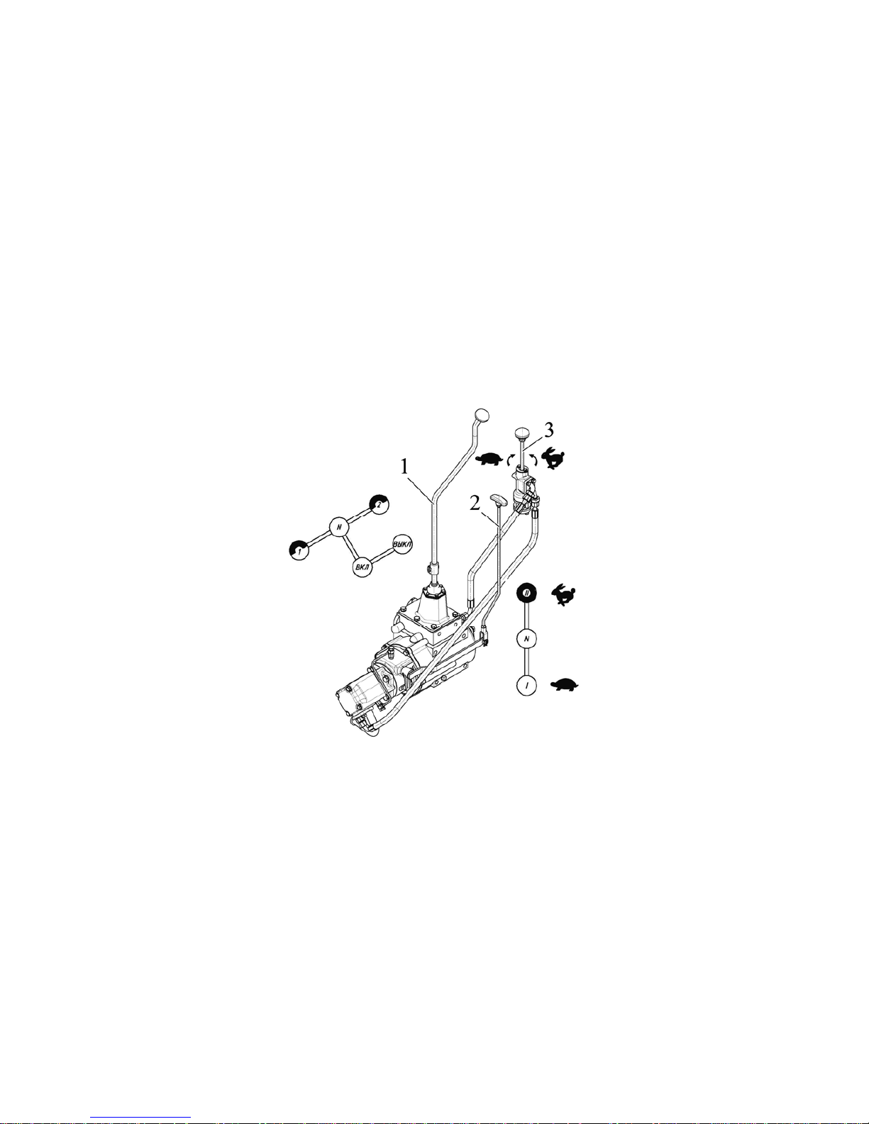
952.5-0000010 OM
65
2.26 Creeper control
Against order your tractor can be equipped with a creeper.
The creeper is intended to be mounted on tractors, coupled with implements, requir-
ing low speeds of travel.
On tractors “BELARUS-952.5” equipped with a speeder in transmission, a mechani-
cal creeper MCR-05 or a hydraulic creeper HCR-05 can be mounted.
On tractors “BELARUS-952.5” equipped with reverse gear unit in transmission, a
mechanical creeper MCR-5 can be mounted.
A mechanical creeper MCR-5 is controlled by ranges shift rod of CR 2 (figure
2.26.1) and shift lever CR 1 (in figure 2.27.1 you can see range shift rod of CR 5, shift
lever CR 6). On tractors equipped with a speeder, MCR-05 mounting enables to obtain 16
additional forward speeds and 16 reverse speeds. On tractors equipped with reverse gear
unit, MCR-05 mounting enables to obtain 8 additional forward speeds and 8 reverse
speeds.
A hydraulic creeper HCR-05 is controlled by range shift rod of CR 2 (figure 2.26.1),
shift lever CR 1 and a throttle handle of CR 3. On tractors equipped with a speeder, HCR05 mounting enables to obtain 16 additional forward speeds and 16 reverse speeds. Turning throttle handle 3 of HCR-05 allows to get stepless speed change while tractor movement with the first range of a hydraulic creeper turned on.
1 – shift lever of a creeper, 2 – range shift rod of creeper, 3 – throttle handle of a
creeper.
Figure 2.26.1 – The scheme of HCR-05 and MCR-05 control.
MCR-05 and HCR-05 can be purchased separately from tractor and be mounted on
a tractor with the help of your dealer. A mechanical creeper MCR-05 mounted on a tractor
can be reequipped into a hydraulic creeper HCR-05.
If your tractor is equipped with a mechanical creeper or a hydraulic creeper, find
service manual on creeper 102-1742000 OM attached where information on technical
equipment operation procedure as well as information on design and troubleshooting of
MCR-05 or HCR-05 is given.
If you order MCR-05 or HCR-05 separately from tractor, service manual on creeper
102-1742000 OM is delivered with a creeper.
Page 66
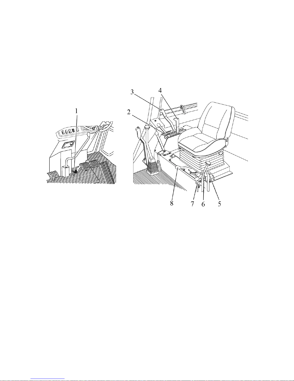
952.5-0000010 OM
66
2.27 Controls of tractor equipped with RLL control system with draft control
unit, mechanical control of rear axle differential lock and rear PTO.
2.27.1 General information
Against order instead of RLL control system with a hydraulic lift your tractor can be
equipped with RLL control system with draft control unit. While draft control unit mounting,
tractor “BELARUS-952.5” is equipped with mechanical control of rear axle differential lock,
mechanical control of rear PTO, RLL lever fixing mechanism in transport position. Tractor
equipped with draft control unit can be equipped with a hydraulic hook (DH-2). Control
elements of the mentioned units and tractor systems are shown in figure 2.27.1.
1 – differential lock control pedal; 2 – stop block of draft control unit lever; 3 – rear
PTO engaging lever; 4 – draft control unit operation handle; 5 – creeper ranges shift rod;
6 – gear shifting lever of a creeper; 7 – hydraulic hook or lowered link gripper tools control
handle; 8 – RLL lever fixing mechanism in transport position.
Figure 2.27.1 – RLL operation by draft control unit, mechanical control of rear axle
differential lock, rear PTO, creeper control.
Tractor equipped with draft control unit can be equipped with adjustable implement
lifting limiter.
2.27.2 Mechanical control of rear axle differential lock.
When pressing the pedal against the stop (figure 2.27.1) rear axle differential lock is
on, when taking the foot off the pedal - rear axle differential lock is off. Rear axle differential lock is used for short-time lock of rear wheels while obstacle crossing.
TRACTOR OPERATION WHEN REAR AXLE DIFFERENTIAL LOCK IS “ON” AT A
SPEED OF MORE THAN 13 KM/H IS FORBIDDEN.
TRACTOR OPERATION ON HARD SURFACE ROADS WITH REAR AXLE DIF-
FERENTIAL LOCK BEING PERMANENTLY “ON” IS FORBIDDEN.
Page 67
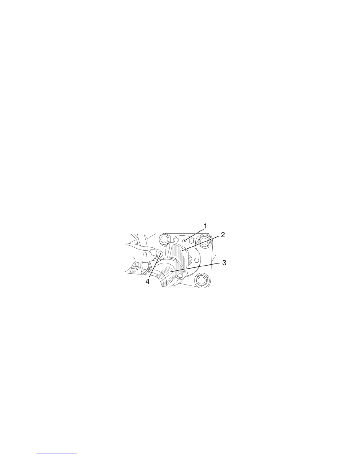
952.5-0000010 OM
67
2.27.3 Rear PTO mechanical control.
Rear PTO mechanical control is exercised by lever 3 (figure 2.27.1).
The rules of rear PTO engagement with mechanical control are specified in subsec-
tion 2.17.2 “Rear power takeoff engagement”.
2.27.4 RLL fixing mechanism control in transport position.
This mechanism is intended to fix RLL in transport position to prevent lowering of
mounted implements.
Lever fixing mechanism of RLL in transport position 8 (figure 2.27.1) has 2 modes:
- “RLL unlocked” – the extreme right position as viewed along tractor movement;
- “RLL locked in upper (transport) position” – the extreme left position.
For RLL locking in transport position do the following:
- lift the implement into the extreme upper position, setting draft control unit handle
4 in the position “Uplift”;
- after fixing RLL in the extreme upper position, turn lever 8 left;
- leave lever 4;
To unlock RLL uplift the implement with handle 4 and turn lever 8 right.
2.27.5 Adjustable implement lifting limiter.
Adjustable implement lifting limiter is mounted on tractor “BELARUS-952.5” with draft
control unit against order.
Limitation of retraction stroke of mounting mechanism rear cylinder rod (the height of
implement lifting) is exercised with adjustable pawl 2 (figure 2.27.2), following the procedure:
- loosen winged nut 4;
- shift adjustable stop 2 along hydraulic cylinder 3 rod into the required position and
tighten winged nut 4 by hand. While lifting the implement onto the required height, adjustable stop 2 will shift hydromechanical valve 1 and lock cylinder cavities.
1 – hydromechanical valve rod; 2 – adjustable stop; 3 – hydraulic cylinder; 4 –
winged nut
Figure 2.27.2 – Adjustable implement lifting limiter
ATTENTION: TO AVOID CAB DAMAGE WITH ELEMENTS OF UPLIFTED IM-
PLEMENTS, ADJUST THE LENGTH OF LEFT AND RIGHT LIFTING RODS IN ACCORDANCE WITH INSTRUCTIONS OF ARTICLE 4.3.3.2 “LIFTING ROD” !
2.27.6 Rear PTO control with draft control unit.
2.27.6.1 General information.
Against order your tractor can be equipped with systems providing the following
methods of control:
- draft control unit providing draft, positional and depth control of agricultural
implements position;
- draft control unit providing draft, positional, mixed and depth control of agri-
cultural implements position.
Page 68
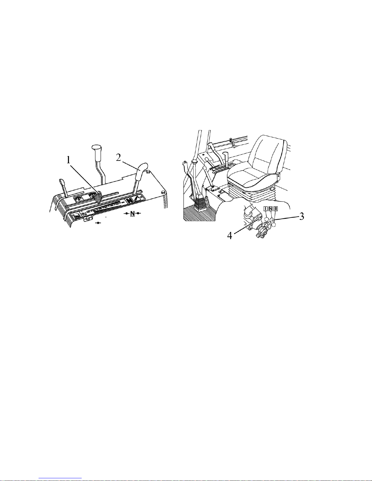
952.5-0000010 OM
68
Determination of draft, positional and mixed control of agricultural implements posi-
tion in the process of tractor operation is specified in section 2.18 “Rear lift linkage control
with a hydraulic lift”.
ATTENTION: IF ANY OF HLL VALVE GROUP LEVERS OR JOYSTICKS IS FIXED
IN THE POSITION “UPLIFT” OR “LOWER”, DRAFT CONTROL UNIT OPERATION IN
THE MODES OF AUTOMATIC CONTROL OF UPLIFTING OR LOWERING IS INTERRUPTED OR PERFORMED WITH ERRORS.
2.27.6.2 Draft control unit operation providing draft, positional and depth control of agri-
cultural implements position.
Draft control unit operation parts providing draft, positional and depth control of agricul-
tural implements position are presented in figure 2.27.3.
1 – stop block of draft control unit lever; 2 – draft control unit handle; 3 – switch of
draft and positional control modes; 4 – handwheel of correction speed regulator.
Figure 2.27.3 – Draft control unit elements of handling providing draft, positional and
depth adjustment of agricultural implements position.
Draft control unit operation is exercised with handle 2 (figure 2.27.3). Beforehand
set a control mode – draft, positional or depth.
Handle 2 has the following positions:
- “N” – “Neutral” (fixed position);
- “Uplift” – extreme rear position (unfixed position). Keep the handle until the uplift of
the implement onto the required height. After loosening the handle it goes back to the position “Neutral”;
- “Forced lowering” – extreme front position (unfixed). Keep the handle until lower-
ing the implement onto the required depth. After loosening the handle it goes back to the
end of the adjustment zone (intermediate “Neutral”).
- “Automatic control range” (adjustment zone) – between the positions “Neutral” and
“Lowering”. The beginning of implement lowering corresponds to the beginning of the adjustment zone (number “1” on the console – minimum operating depth). The end of the adjustment zone corresponds to the maximum operating depth (number “7” on the console).
Switch 3 is intended for shifting force, positional and depth control. To access this
switch, remove the lid under the seat. The switch has the following positions:
- “N” – Off (depth control);
- “II” – Draft control;
- “I” – Positional control.
ATTENTION: BEFORE SETTING THE SWITCH INTO THE SELECTED POSITION, UPLIFT RLL INTO THE EXTREME UPPER POSITION !
Uplift
Lowering
Control zone
Page 69
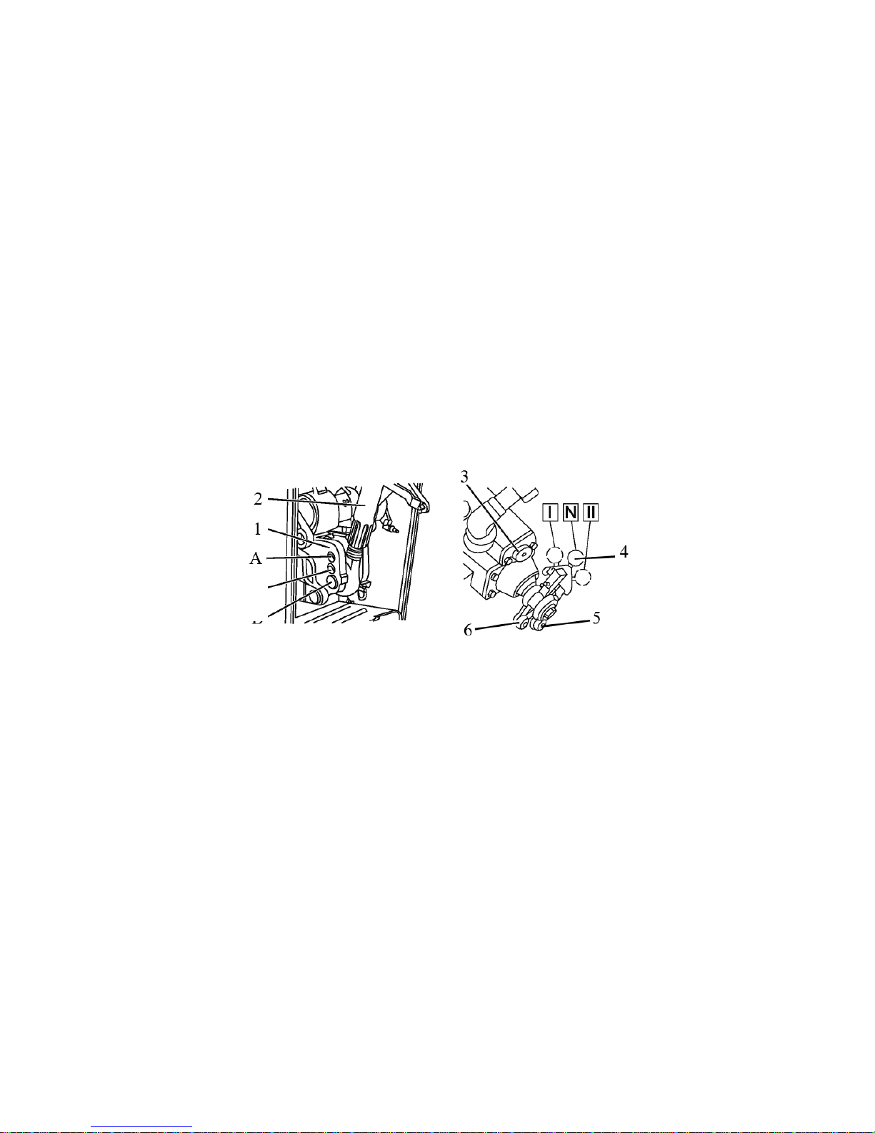
952.5-0000010 OM
69
Handwheel of correction speed regulator 4 is intended for implements position cor-
rection speed adjustment while tractor operation and also for RLL uplifting and lowering
speed setting. While handwheel 4 rotation clockwise correction speed decreases, while its
rotation anti-clockwise – correction speed increases. Handwheel 4 adjustment is to be
done after finishing RLL and mounted implements (plough, cultivator, etc.) controls.
While preparing the machine for operation using draft control mode, do the following:
- set upper link 2 (figure 2.27.4) of the mounted implement onto the upper hole of
clevis 1 (position “A” in figure 2.27.4);
- couple the mounted implement (machine) with tractor RLL;
- if necessary, adjust RLL and the mounted implement;
- switch on draft control mode by uplifting the mounted implement (machine) into the
extreme upper position, turn switch 4 into the power lever 5 groove by turning the
switch left (as viewed along tractor movement) into the position “II”. For easier
switching on before groove entrance, take the switch forward (as viewed along
tractor movement) until it couples with the groove on lever 5;
- adjust handwheel of correction speed regulator 3. While handwheel rotation
clockwise, correction speed decreases, while its rotation anti-clockwise correction speed increases. Turning the handwheel try to obtain smooth depth automatic control in operation process. Do not roll up the handwheel clockwise
against the stop as it will cause too slow uplifting of the implement (machine)
and result in increased frictional slipping of tractor driving wheels;
1 – clevis; 2 – upper link; 3 – handwheel of correction speed regulator; 4 – control
mode switch; 5 – power lever groove; 6 – positional lever groove.
Figure 2.27.4 – Positions of the switch for upper link control while draft control
mode.
At the beginning of operation lower the mounted machine by turning handle 2
(figure 2.27.3) forward. The further forward the handle is set, the deeper cultivation is.
While pulling handle 2 the depth will be less. After adjustment of the required depth, take
limiter 1 along the console groove against the stop into the handle and fix it.
At the end of operation the implement is raised by setting handle 2 into the position
“uplift” – pull against the stop. After finishing uplifting the handle shall naturally return to the
neutral position “N”.
At the beginning of each next operation lower the implement by shifting handle 2
forward against the stop into limiter 1.
While tillage in those cases when setting draft control unit handle forward at the
maximum depth does not provide the sufficient depth, shift upper link 2 of the mounted implement into intermediate hole of clevis 1 (position “B” in figure 2.27.4);
Adjustment of correction speed handwheel and selection of clevis hole while setting
upper link is to be done for specific soil conditions and each type of agricultural machines.
No changeover is required during the operation process.
B
C
Page 70

952.5-0000010 OM
70
While using the positional control mode draft control unit provides automatic support
of the agricultural machine command position in relation to the tractor frame. While tillage
with mounted ploughs, cultivators for bund and interrow cultivation as well as for subsoiling, it is recommended to use positional control amid flat field relief.
It is necessary to use support wheels on wide-span implements coupled with tractor
while using the positional control mode in order to eliminate agricultural machine transverse wracking, to improve straightness of implement moving and to create better conditions for relief copying in broadside direction (in relation to tractor moving).
While preparing the implement for operation using the positional control mode, do
the following:
- set upper link 2 (figure 2.27.4) of the mounted implement onto the upper link
hole 1 (position “A” in figure 2.27.4);
- couple the mounted implement (machine) with tractor RLL;
- if necessary adjust RLL and the mounted implement;
- switch on the positional control mode by uplifting the mounted implement (ma-
chine) into the extreme upper position, set switch 4 into the positional lever 6
groove by turning the switch right (as viewed along tractor movement) into the
position “I”. For easier switching on before groove entrance, take the switch forward (as viewed along tractor movement) until it couples with the groove on
lever 6;
- turn handwheel of correction speed 3 contraclockwise against the stop setting
maximum uplifting speed at automatic position correction.
At the beginning of operation set the mounted implement into the required position.
Lowering is exercised by shifting handle 2 (figure 2.27.3) forward. The further forward the
handle is set, the lower the implement goes. After fixing the implement into the required
position along the full vertical extent, shift limiter 1 into the handle against the stop and fix
it.
At the end of operation pull handle 2 against the stop to uplift the implement into
transport position. After finishing uplifting, the handle shall naturally return to the neutral
position “N”.
At the beginning of each next operation lower the implement by shifting handle 2
forward against the stop into limiter 1.
Depth control can be applied while tractor coupling with mounted implements that
have support wheels. It implies that the selected depth of cultivation is provided by setting
the specific depth of the coupling with tractor agricultural implement support wheel.
While depth control, set switch 4 (figure 2.27.4) into intermediate position “N”, uplift-
ing RLL into the extreme upper position before that. For implement uplifting pull handle 2
(figure 2.27.3) against the stop and hold it till finishing uplifting, after which the handle shall
naturally return into its neutral position “N”. Lowering is exercised by shifting handle 2 forward into the adjustment zone till the beginning of implement lowering.
Upper link 2 (figure 2.27.4) of the mounted implement is to be set upon the lower
hole of clevis 1 (position “C” in figure 2.27.4);
It is forbidden to set handle 2 in the position “forced lowering” (forward against the
stop) at depth control mode if a mounted implement is coupled with RLL. Use the position
“forced lowering” only while implement coupling with tractor lift linkage. For forced lowering
turn handle 2 into the extreme forward position. After loosening the handle it shall return to
the adjustment zone (intermediate neutral) and RLL lowering shall stop.
Page 71
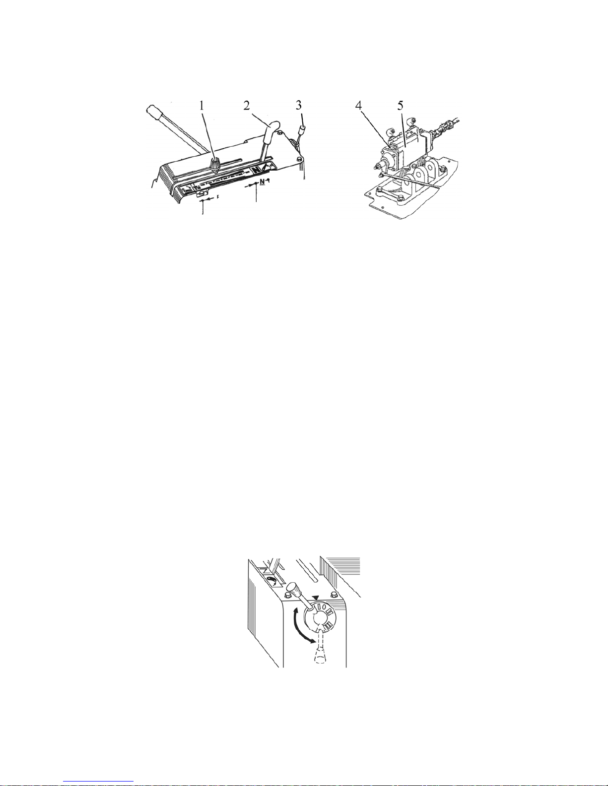
952.5-0000010 OM
71
2.27.6.3 Draft control unit operation providing draft, positional, mixed and depth con-
trol of agricultural implements position.
Draft control unit operation parts providing draft, positional, mixed and depth control
of agricultural implements position are presented in figure 2.27.5.
1 – stop block of draft control unit lever; 2 – draft control unit handle; 3 – switch
handle of draft, positional and mixed control; 4 – handwheel of correction speed regulator;
5 – draft control unit.
Figure 2.27.5 – Draft control unit operation parts providing draft, positional, mixed
and depth agricultural implements position.
The differences between the draft control unit presented in article 2.27.6.3 and the
draft control unit presented in article 2.27.6.2 are the following:
- additionally to draft, positional and depth control modes of agricultural implements
position, a mixed control mode is provided;
- switching the control mode is exercised by handle 3 situated at the back of the
console. Handle 3 controls signal mixing switch situated under the cab on the rear axle
body lid.
Handwheel of correction speed regulator 4 (figure 2.27.5) is situated on draft con-
trol unit 5. To access the handwheel remove the lid under the seat on the left side.
Switching the control mode is exercised in the following way:
- set RLL into the extreme upper position with handle 2 (figure 2.27.5);
- set control mode switch handle 3 into the required position overlapping the
marks depicted on the round division collar of the handle with the mark “” on the upper
plate of the control console. Mark “I” is positional adjustment, mark “III” is draft adjustment,
the position between marks “I” and “III” is a mixed adjustment zone.
- according to the selected control mode set the handwheel of correction speed 4
regulator into the required position as it is specified in article 2.27.6.2.
- further RLL control is exercised by handle 2 according to article 2.27.6.2. While
draft or mixed control, adjust the handwheel of correction speed and selection of hole in a
link, setting upper link as it is specified in article 2.27.6.2. For getting depth control mode,
set handle 2 into the position “Neutral” at which control mode handle 3 can be in any position.
The scheme of mode switch 3 handle control is presented in figure 2.27.6.
Figure 2.27.6 – The scheme of draft, positional and mixed control mode switch han-
dle control.
Uplift
Control
zone
Lowering
N
eutral
Page 72
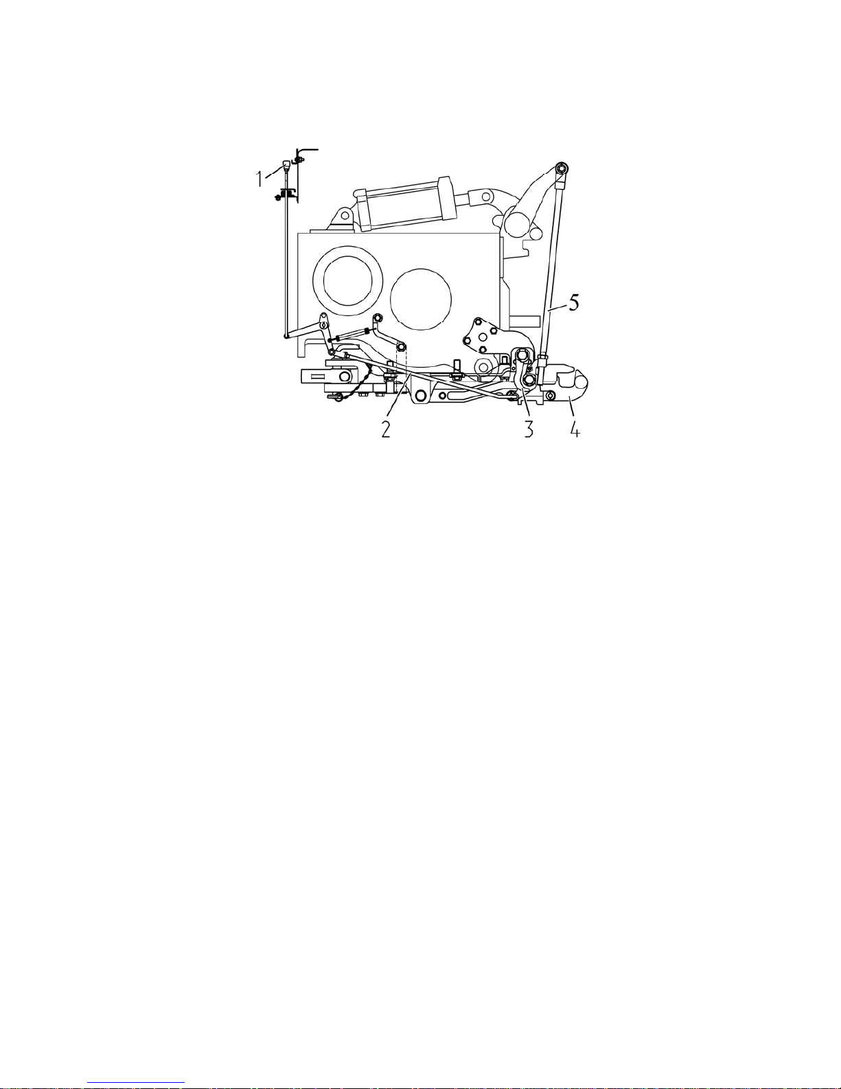
952.5-0000010 OM
72
2.27.7 Hydraulic hook or lowered link grippers control.
Against order tractor with draft control unit can be equipped with a drawn hydraulic
hook (hydraulic pick-up hitch). Hydraulic hook is intended for operation with semi trailers
and agricultural machines on their basis.
1 – hydraulic hook gripping handle control; 2 – control link; 3 – grippers; 4 – hook
with axle; 5 – uplifting links.
Figure 2.27.7 – The scheme of hydraulic hook control.
Agricultural machines coupling with the hydraulic hook is exercised in the following way:
- using handle 1 (figure 2.27.7) installed in the cab, turn grippers 3 through control link 2
loosing hook 4 axle;
- setting RLL into the lower position by draft control unit operation handle, set hook 4 be-
low the coupled machine loop level;
- slowly move to the position where hook mouth 4 is under the loop and fix hook 4 axle in
gripper tools 3, uplifting RLL into the upper position.
For discoupling of the agricultural machine from hydraulic hook do the following:
- turn handle 1 into the upper position;
- lower RLL and move forward on tractor;
- uplift RLL into the upper position, fix hook 4 axle in gripper tools 3.
Against order tractor with draft control unit can be equipped with lowered link in-
tended for coupling with semitrailers and trailing agricultural machines.
Coupling and decoupling of agricultural implements to lowered link is exercised in
the same way as to the hydraulic hook.
Page 73

952.5-0000010 OM
73
3 INTENDED USE OF TRACTOR
3.1 Safety measures to be taken preparing tractor for operation
Strict observance of safety requirements ensures safe operation of the tractor and
improves its reliability and durability.
Only persons not younger than 17, holders of a tractor driving license, who have
been briefed on accident and fire prevention, may be admitted to operate the tractor of
drawbar category 1.4.
Prior to operating the tractor, scrutinize the Operator’s Manual and the Engine op-
eration manual. Insufficient knowledge of tractor controls and servicing is a potential of
likely accidents.
When performing depreservation of the tractor and optional equipment, follow the fire
prevention instructions and sanitary requirements when dealing with chemicals, rag wastes and
oiled paper.
Before starting to operate the tractor replace special nuts of rear wheel hubs (one at
each hub), used for tractor fastening on the vehicle platform, with the nuts of basic hub configuration, attached in a set of spare parts, tools and accessories. Tighten the nuts with a torque of
300…350 Nm. Replace special nuts of front wheels (one at each wheel), used for tractor fastening on the vehicle platform, with the nuts of basic wheel configuration, attached in a set of
spare parts, tools and accessories. Tighten the nuts with a torque of 200…250 Nm.
The tractor should be run in, in accordance with the requirements under subsection
3.4 “Tractor final assembly and run in”.
The tractor should be completely outfitted and in good working order.
DO NOT allow dismantling of design-stipulated protective enclosures or safeguards
from the tractor, as well as other parts and assembly units which affect its safe operation
(protective guard of the fan, rear PTO enclosure, etc.)
The technical condition of the braking system, steering controls, lighting and indication devices and the drive system should conform to safety requirements of relevant standards and the present Manual.
The trailed agricultural machines and harvest trailers shall be fitted with rigid coupling which excludes swaying and colliding thereof with the tractor during the transportation.
The tractor controls shall be provided with reliable locking in their operative posi-
tions.
Keep all the warning tabs of the tractor clean and readable. If damaged or lost, re-
place them with new ones.
Tractor use without availability of the accumulator battery in the electrical equipment
system is not allowed.
The first aid kit shall be completed as per regulations, adopted in the territory of the
state, where the tractor is used.
Page 74

952.5-0000010 OM
74
3.2 Tractor use
3.2.1 Boarding the tractor
The tractor is boarded through the cab left door. To make tractor boarding easier
there is a foot step.
3.2.2 Preparing for start and starting the engine
To start the engine of tractor “BELARUS-952.5” perform the following actions:
- engage the tractor parking brake;
- if required, fill in fuel and bleed the fuel delivery system to remove air (on tractors
with draft control unit open the valves of fuel tanks if they are closed);
- set the fuel feed control handle into the position that corresponds to the minimum
fuel supply;
- make sure that the electronic pedal of fuel feed control is in its initial position and it
is not affected by physical influence. Do not press the fuel feed control pedal when starting
the engine;
- FDA drive control lever shall be set in “FDA off" position
- set the rear PTO drive handle into position “PTO drive off”, and the rear PTO ac-
tuating key into position “PTO off” (on tractors with draft control unit rear PTO actuating lever
shall be in position “PTO off”) .
- the handles of the hydraulic system valve group control (or joystick with lever)
shall stay in “neutral” position, the switch (or pedal) of the rear axle DL, shall stay in “off” position;
- set the levers shifting the GB ranges and speeds into a neutral position;
- turn on the accumulator battery switch;
- turn the key of the starter and instruments switch from “0” position into position “I”.
Herewith:
1) On the integrated indicator both RPTO scale range annunciators as well as all
RPTO scale segments will turn on for not more than one second, and the needles of engine
speed and rpm indicators deviate from their initial positions (or the needles “shake” on indicator zero marks for not more than one second) – thus confirming workability of LED annunciators and needle indicators.
2) The engine control system panel carries out a self-check. If there are no errors in
the system operation, the fault testing annunciator on the engine control system panel shall
light up and go out, thus confirming workability of the annunciator lamp and its correct connection to the tractor on-board system. If the errors are detected, the testing annunciator
provides a light code of the fault. The detected faults shall be eliminated before the engine is
started.
3) The information screen displays a company logo for several seconds – thus con-
firming workability of the screen. Then in case there are no failures with the EECS operation,
the information screen functions in operation mode – it displays actually measured parameters of the engine. If failures are detected, the information screen produces an acoustic signal, and a brief description of the detected failures emerges on the screen. The failures detected shall be eliminated before the engine is started.
4) On the pilot lamp unit a pilot lamp of emergency oil pressure in HSC will light up.
On the dashboard a signal lamp of oil emergency pressure in engine lubrication system (and
a buzzer sounds), a signal lamp of air emergency pressure in the pneumatic system (if it is
below the accepted value), a signal lamp of fuel reserve capacity in the tank (when reserve
volume of fuel remains in the tank). On the integrated indicator a pilot signal annunciator of
engaged parking brake will turn on in a flashing mode with 1 Hz frequency.
5) On the pilot lamp unit a pilot lamp that indicates heating plug operation will light up.
- after the heating plug pilot lamp goes out, start the engine, to do this depress the
clutch pedal and turn the key of starter and instruments switch from “I” position (“instruments on”) into position “II” (engine start);
- hold the key of the starter switch turned until the engine is started, but not longer
than 15…20 seconds; if the engine has not started, a repeated start-up shall be carried out
not earlier than after one minute;
Page 75

952.5-0000010 OM
75
- after the engine is started, release the clutch pedal, check function of all signal
lamps and gauge indications (coolant temperature, oil pressure in the engine, on-board
circuit voltage, etc.). Let the engine run at low rpm until pressure stabilizes within gauge
operation range. Actually measured parameters and operation states of tractor systems
and units are displayed on the integrated indicator, on the dashboard, on the pilot lamp
unit, on the control panel of the rear axle DL, and rear PTO (with hydraulically operated lift
installed), on the engine control system panel and on the information screen. On RLL control panel the annunciator of testing electronic systems controlling RLL, lights up, thus indicating the workability and blocking of the RLL control system;
IT IS FORBIDDEN TO OPERATE THE TRACTOR IN CLOSED ROOMS WITHOUT
A REQUIRED VENTILATION (AIR EXCHANGE). EXHAUST GASES MAY LEAD TO A
LETHAL OUTCOME!
IT IS FORBIDDEN TO RUN THE ENGINE WITH THE SYSTEMS OF COOLING
AND ENGINE LUBRICATION UNFILLED!
ATTENTION: THE TRACTOR CAB IS EQUIPPED WITH A SINGLE-OCCUPANCY
SEAT AND THE OPERATOR IS THE ONLY PERSON TO STAY IN!
ATTENTION: START THE ENGINE AND INSPECT GAUGES ONLY WHEN STAY-
ING IN THE OPERATOR'S SEAT!
ATTENTION: KEEP IN MIND THAT THE ENGINE START IS POSSIBLE ONLY
WHEN THE GEAR-CHANGE LEVER IS SET INTO A NEUTRAL POSITION!
ATTENTION: THERE MUST BE NO PEOPLE UNDER BEFORE AND BEHIND
THE TRACTOR, AND BETWEEN THE TRACTOR AND AN IMPLEMENT COUPLED TO
IT!
IT IS FORBIDDEN TO START THE ENGINE TAKING THE TRACTOR IN TOW, AS
IT MAY RESULT IN ENGINE BREAKDOWN. START THE ENGINE ONLY WHEN YOU
STAY IN THE OPERATOR'S SEAT!
3.2.3 Tractor motion start, GB shifting
ATTENTION: YOUR TRACTOR IS EQUIPPED WITH TURBOCHARGED
ENGINE. HIGH SPEED OF THE TURBOCHARGER REQUIRES GOOD LUBRICATION
AT ENGINE START. AFTER STARTED WARM UP THE ENGINE TO ACHIEVE STABLE
RUNNING UNDER THE CRANKSHAFT SPEED OF 1000-1300 RPM (FOR 2-3 MIN),
AND THEN LET IT RUN AT HIGHER SPEED, GRADUALLY INCREASING THE SPEED
UP TO 1600 RPM (NOT MORE) UNTIL THE COOLANT TEMPERATURE REACHES
40°C.
TRACTOR OPERATION IS FORBIDDEN, IF THE ENGINE EMERGENCY OIL
PRESSURE LAMP IS ON WITH THE ENGINE RUNNING, STOP THE ENGINE IMMEDIATELY!
Before starting to move define a necessary speed of tractor movement. The speed
diagram of the tractor “BELARUS-952.5” with tires of basic configuration is given in the
instruction table attached to the right glass of the cab and also in subsection 2.14. “Gears
shifting”.
To put the tractor in motion the following shall be done:
- reduce engine speed;
- depress the clutch pedal;
Page 76

952.5-0000010 OM
76
- on tractors with double-lever GB control set a required gearbox range using the range
and gears shifting lever as per the range shifting diagram, than set a desired speed, for this
shift the range and gears shifting lever from neutral (“N”) into any of positions, as per the
speed shifting diagram;
- on tractors with single-lever GB control set a required gearbox range using the range and
gears shifting lever as per the range shifting diagram, than set a desired speed, for this shift the
range and gears shifting lever into any of positions, as per the speed shifting diagram;
- if necessary change the speed of speed increaser (for tractors with reverse gear
unit change reverse gear unit for necessary tractor movement);
- disengage the parking break, slowly release the clutch pedal, increasing at
the same time fuel feed. The tractor will start moving.
IT IS FORBIDDEN TO START MOVEMENT WITH BIG TRACTION LOAD!
IT IS FORBIDDEN TO MOVE THE TRACTOR WITH THE DOOR OPEN!
ATTENTION: SHIFT RANGES AND GEARS OF THE GEARBOX ONLY WITH THE TRACTOR STOPPED AND THE CLUTCH PEDAL FULLY DEPRESSED! PERFORMING TRANSPORT OPERATION IT IS PERMITTED TO SHIFT GEARS IN MOTION FROM THE SECOND
TO THE THIRD, FROM THE THIRD TO THE SECOND WITHIN THE I
st
AND THE II
nd
RANGE, AND ALSO FROM THE SECOND TO THE FOURTH, FROM THE FOURTH TO THE
SECOND, FROM THE THIRD TO THE FOURTH, FROM THE FOURTH TO THE THIRD
WITHIN THE II
nd
RANGE. THE SHIFTING SHALL BE CARRIED OUT WHEN THE TRACTOR
COASTS AND THE CLUTCH PEDAL IS FULLY DEPRESSED! ENGAGEMENT AND DISENGAGEMENT OF THE FIRST GEAR, DOWNSHIFTING TO THE FIRST GEAR, ENGAGEMENT AND DISENGAGEMENT OF THE REVERSE GEAR SHALL BE CARRIED OUT ONLY
WITH THE TRACTOR FULLY STOPPED AND WITH THE CLUTCH PEDAL FULLY DEPRESSED!
ATTENTION: TO ENGAGE THE SPEED SMOOTHLY, WITHOUT SHARP
PUSHES, MOVE THE SPEED LEVER ACCORDING TO THE DIAGRAM AND HOLD IT
PRESSED UNTIL THE SPEED IS FULLY ENGAGED!
ATTENTION: YOU CAN GET INTO FOURTH GEAR ONLY IF THE IInd RANGE IS SET!
ATTENTION: THE PASSES OF THE SPEED-INCREASE GEAR UNIT CAN BE SHIFTED USING ANY
GB GEAR ONLY WITH THE TRACTOR STOPPED AND THE CLUTCH PEDAL FULLY DEPRESSED. PERFORMING TRANSPORT OPERATION IT IS PERMITTED TO SHIFT PASSES
OF THE SPEED-INCREASE GEAR UNIT IN MOTION AS THE TRACTOR COASTS AND THE
CLUTCH PEDAL IS FULLY DEPRESSED!
ATTENTION: ON TRACTORS EQUIPPED WITH SPEED-INCREASE GEAR UNIT
THE FOLLOWING IS FORBIDDEN:
- LONG-TERM OPERATION IN REVERSE GEAR “R”;
- USE OF REVERSE GEAR “R” IN TRACTION MODE;
-SHIFT THE REVERSE GEAR “R” ON TRACTORS EQUIPPED WITH SPEEDINCREASE GEAR UNIT ONLY FOR TRACTOR MANEUVERING. THE TRACTORS INTENDED FOR WORKS REQUIRING LONG-TERM TRACTOR USE IN REVERSE GEAR
AND USE OF REVERSE GEAR IN TRACTION MODE ARE EQUIPPED WITH REVERSE
GEAR UNIT!
ATTENTION: GEARBOX OF THE TRACTOR EQUIPPED WITH THE REVERSE
GEAR UNIT DOES NOT HAVE A REVERSE GEAR. YOU CHOOSE THE DIRECTION OF
MOVEMENT BY SHIFTING THE CORRESPONDENT PASS OF THE REVERSE GEAR
UNIT.
Page 77

952.5-0000010 OM
77
ATTENTION: THE PASSES SWITCHING OF THE REVERSE GEAR UNIT FROM
THE FORWARD TO THE REVERSE GEAR AND FROM THE REVERSE TO THE FORWARD GEAR IS CARRIED OUT ON THE FIRST, THE SECOND AND THE THIRD GEAR
OF THE Ist OR THE IInd RANGE OF THE GB WITH THE TRACTOR STOPPED AND THE
CLUTCH PEDAL FULLY DEPRESSED. MOVEMENT ON THE FOURTH GEAR IS POSSIBLE ONLY FORWARD!
ATTENTION: STARTING TO MOVE, MAKE SURE THE PARKING BRAKE
IS DISENGAGED!
ATTENTION: DON’T HOLD THE FOOT ON THE CLUTCH PEDAL DURING TRACTOR OPERATION, BECAUSE IT CAN LEAD TO CLUTCH SLIPPING, ITS OVERHEATING
AND FAILURE!
ATTENTION: WITH THE DIFFERENTIAL LOCK ENGAGED THE TRACTOR
MOVEMENT SHALL NOT EXCEED 13 KM/H!
ATTENTION: OPERATING ON ROADS WITH HARD SURFACE IT IS NECESSARY TO SWITCH THE FDA DRIVE OFF TO AVOID INCREASE WEAR OF FRONT
WHEELS!
ATTENTION: IT IS ALLOWED TO USE THE ENGINE AT ITS FULL POWER ONLY
AS THE COOLANT TEMPERATURE REACHES 70°C.
ATTENTION: TRACTOR OPERATION WITH EMPTY AdBlue (UREA) TANK IS
NOT ALLOWED! WHEN INFORMATION ABOUT CRITICAL LEVEL OF AdBlue AGENT
(UREA) IN THE TANK APPEARS ON MONITOR, IT IS NECESSARY TO FILL THE TANK
WITH AdBlue AGENT.
Page 78

952.5-0000010 OM
78
3.2.4 Tractor stop
To stop the tractor do the following:
- decrease engine speed;
- fully press the clutch pedal;
-on tractors with double-lever GB control set gear shifting lever in neutral position;
- on tractors with single-lever GB set range and gear lever in neutral position;
- release the clutch pedal;
- stop the tractor by means of service brakes;
- engage the parking brake.
ATTENTION: FOR TRACTOR EMERGENCY STOP SHARPLY PRESS THE
CLUTCH AND BREAK PEDALS TOGETHER!
3.2.5 Engine stop
ATTENTION: BEFORE STOPPING THE ENGINE, MOVE DOWN THE LIFT LINKAGES UNTIL THEY REACH GROUND, IF THEY ARE UPLIFTED; LET THE ENGINE
RUN AT (1000±100) RPM FOR 3 TO 5 MINUTES. THIS WILL ALLOW TO REDUCE ENGINE COOLANT TEMPERATURE!
To stop the engine do the following:
- set the rear PTO control key into position “off” (on tractors with draft control unit
rear PTO actuating lever shall be in position “PTO off”) and the rear PTO lever changing the
drive from independent to synchronous one (is the synchronous drive is installed) set into
“Neutral” position;
- disengage the rear axle differential lock;
- set the FDA drive control lever in “FDA off” position
- put the implement down on the ground;
- shift the hydraulic lift linkage distribution valve group control lever into neutral position;
- turn the conditioner or heater fan off;
- turn the key of the starter and instruments switch from the position “I” into the position “0”;
- in case the rear PTO independent drive is off, set the rear PTO lever changing the drive
from independent to synchronous one into “Neutral” position;
- deactivate the accumulator battery when the engine is stopped for a long time.
ATTENTION: FOR ENGINE EMERGENCY STOP TURN THE KEY OF THE
STARTER AND INSTRUMENTS SWITCH FROM THE POSITION “I” INTO THE POSITION “0”!
3.2.6 Leaving the tractor
Leaving the tractor is carried out through the cab left door, except for emergency
situations. Rules on leaving the tractor at emergency situations are given in clause 3.5.3 of
subsection 3.5 “Emergency actions”.
Leaving the tractor, make sure that all actions, listed in subsection 3.2.5 “Engine
stop” have been performed, lift linkages of the tractor and of coupled implements have
been lowered.
3.2.7 PTO use
The rules on engagement and disengagement of rear power take off shaft are described in subsection 2.17 “Rear power takeoff control”.
The rear power take off shaft operation is controlled by means of the integrated indicator as described in subsection 2.8.2 “Assignment and operation principle of integrated
indicator gauges”.
The rules of RPTO coupling with different types of agricultural machines and implements are described in section 4 “Coupling of implements”.
ATTENTION: OPERATING WITH PTO OBSERVE ALL SAFETY MEASURES OF PTO
OPERATION, WHICH ARE LISTED IN THE THIS OPERATION MANUAL!
Page 79
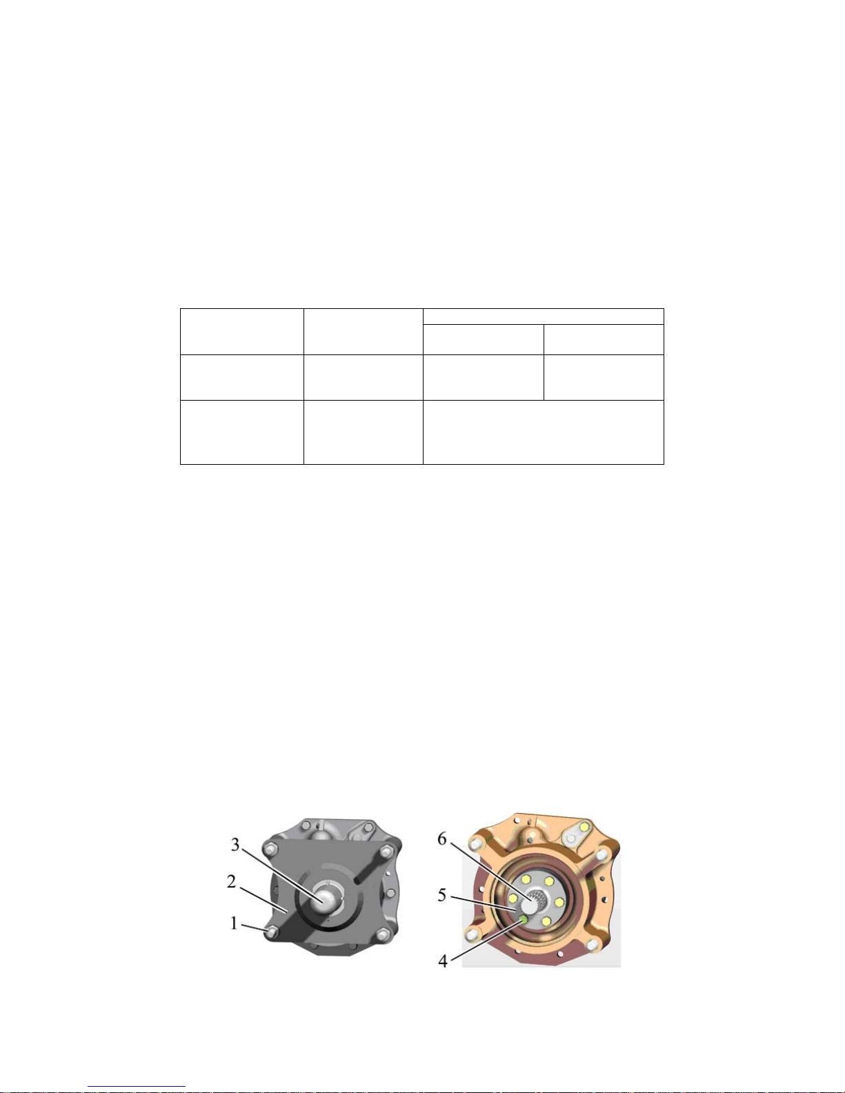
952.5-0000010 OM
79
ATTENTION: TO EXCLUDE IMPACT LOADS ENGAGE THE REAR PTO AT ENGINE SPEED CLOSE TO MINIMUM (BETWEEN 1000 AND 1100 RPM), THEN ENGINE
SPEED SHOULD BE INCREASED.
The rear PTO of the tractor has a PTO end 1 (6 splines, 540 rpm) installed. Against order a PTO end 1c (8 splines, 540 rpm) and a PTO end 2 (21 splines, 1000 rpm) can be attached to the spare parts, tools and accessories kit of the tractor.
In their design and arrangement the rear PTO ends of “BELARUS-952.5” tractor correspond to regulations and standards, applicable to PTO shafts of agricultural tractors.
ATTENTION: ON TRACTOR „BELARUS-952.5“ POWER TAKE OFF THROUGH
REAR PTO AT 540 RPM MODE SHOULD NOT EXCEED 60 kW!
ATTENTION: ON TRACTOR “BELARUS-952.5” POWER TAKE OFF THROUGH
REAR PTO AT 1000 RPM MODE SHOULD NOT EXCEED 67 kW!
Table 3.1 – Operating modes of rear power take-off shaft
Rotation speed, min-1
PTO drive
Shaft end
extension
PTO
of engine cardan
shaft
Independent
PTO 1С
PTO 1
PTO 2
540
540
1000
1632
1632
1673
Synchronous with
mounted rear tires
18.4R34
PTO 1С
PTO 1
PTO 2
- 3,36 rotation/meter of track
PTO shaft end rotation speed when the rated frequency of the engine crankshaft is
1800 min-1, (when independent drive is on) is as follows:
PTO 1С - 596 min-1
PTO 1 - 596 min-1
PTO 2 - 1076 min-1
At operation with rear power take-off shaft in ground-speed mode the following shall be
taken into account:
- PTO shaft end extension can rotate only when the tractor moves;
- operating tractor speed in structure of machine-tractor unit shall not exceed 8 km/h;
- the direction of rotation of PTO shaft end extension (on looking at PTO shaft end extension ) is different at forward and back motion: at forward motion is clockwise, at back motion is counterclockwise.
For operation with PTO, remove the protective cap 3 (figure 3.2.1), that protects
shaft end extension 6. For this it is necessary to squeeze the protective cap at its bottom
and pull down. After finishing to operate with PTO it is obligatory that you put the protective
cap back, to do this it is required to put the cap on the shaft end extension and to press it
length way till the cap is securely fixed in the aperture of the plate 2.
If the cap is fixed by bolts, for operation with PTO, take off a protective cap that pro-
tects a shaft end extension, for this unscrew two fixing bolts. After finishing to operate with
PTO it is obligatory that you put the protective cap back, by screwing of two bolts.
1 – nut; 2 – plate; 3 – cap; 4 – bolt; 5 – plate; 6 – shaft end extension.
Figure 3.2.1 –Protective cap removal and exchange of PTO shaft end extension.
Page 80

952.5-0000010 OM
80
To exchange the PTO shaft end extension proceed as follows:
- loosen four nuts 1 and remove plate 2 with cap 3;
- unscrew sex bolts 4 remove plate 5 and shaft end extension 6;
- mount the other shaft end extension into spline opening, preliminary lubricated
with grease center pilot, mount the plate 5, tighten the bolts 4, mount the plate 2 and
fasten it with nuts 1.
3.2.8 Selection of optimal inner pressure in tires depending on operational
conditions and load on tractor axles
3.2.8.1 Selection of optimal inner pressure in tires depending on operational
conditions and load on tractor axles.
Selection of optimal air pressure in tires of wheeled tractors and rate of its influence on
gripping abilities depend on soil type and load, applied to tractor axles. Air pressure in tires influences the wheel point being in contact with soil, and affects its gripping abilities as well as
tractor operational performance depending on soil conditions. Rates of loads on tires to select
operation mode at various inner pressures and speeds are set forth by a tire manufacturer and
are provided in table 3.2.
The pressure value depends on travel speed and weight loads on tractor axles, created
by weight of coupled implements with due account for tractor own weight and ballast weight
and also operation conditions.
Inner pressure in tires for each specific case of tractor coupling with implements is different. Therefore if tractor operational conditions are changed it is required to check and if
necessary adjust pressure value in tires. Failure to comply with pressure rates decreases tire
life significantly.
Tractor operation with tire pressure set below the required rate results in the following
wheel failures:
- tire turning on rims;
- wearing of tire bead against rim edge;
- occurrence of cracks on tire sides;
- ply separation or rupture of a tire;
- tear-out of tire valve (for tubed tires);
Operation with tire pressure higher than the rated pressure results in the following
wheel failures:
- noticeable increased wear of tires;
- stretching of carcass layers and decrease of tire flexibility;
- increased skidding of wheels;
- increased sensitivity to impacts and cuts.
Extra duty operation resulting in excess of max. load capacity (for given pressure and
speed) of tires and tractor axles is a reason for failures and damages not only to the undercarriage (tire carcass rupture, etc.) but also to other units and parts of the tractor, which can lead
to accidents and decrease of the tractor life span in general.
ATTENTION: ALWAYS SET TIRE PRESSURE WITH DUE ACCOUNT FOR LOADS
AND SPEEDS EFFECTIVE FOR THE KIND OF OPERATION BEING CARRIED OUT!
Correct choosing tire pressure as well as identifying if it is necessary to mount ballast weights,
their mass and type is possible only after defining a load value on tractor axles.
The exact load value for a specific case of tractor use, which is applied to front and rear
wheels of the tractor, can be determined only by way of practical weighing the tractor with the
implement coupled.
The method of identifying load on front and rear wheels of the tractor by way of weighing is presented in section 4 “Coupling of implements”.
To check tire pressure use properly-functioning devices with scale interval not more
than 10 kPa. This will ensure adequacy of measurements. The permissible limit deviations for
tire pressure are ± 10 kPa according to pressure gage readings.
Page 81

952.5-0000010 OM
81
Rates of loads on single tires of tractors “BELARUS-952.5” to select operation
mode at various inner pressures and speeds are provided in table 3.2.
Table 3.2
Loading of tire, kg,
at inner pressure, kPa
Tire
Load
index**
Speed
symbol**
Speed,
km/h
80 100 120 140 160 180
360/70R24 122 A8
10
20
30
40
1500
1340
1165
1090
1635
1450
1265
1180
1775
1580
1375
1285
1910
1720
1500
1400
2045
1845
1605
1500
2250
(190
kPa)
18.4R34 144 А8
10*
20
30
40
3030
2480
2160
2020
3330
2730
2375
2220
3615
2960
2575
2410
3915
3210
2790
2610
4200
3440
2995
2800
* - inner pressure shall be increased by 25 %
** Load index and speed symbol (see on tire sidewall).
Rates of loads are provided for tires with indicated load index and speed symbol.
Pressure shall be set in “cold” tires.
Performing operations, requiring large pulling force on the hook, set the pressure as for
the speed of 30 km/h. When performing transport operations on roads with solid sur-
face increase the pressure by 30 kPa.
Tractor operation with twinned tires is permitted only at the speed of 20 km/h.
Total loading capacity of twinned tires shall not exceed the loading capacity of a single
tire by more than 1,7 times;
When twinning, make sure the pressure of outer tires is 1,2 – 1,25 times lower, than the
pressure of inner tires.
3.2.8.2 Tire inflation
Inflate tires through an air bleed valve of a pressure regulator 1 (figure 3.2.2), for this do
the following:
- let air out of a balloon 3 of the pneumatic system through a condensate removing
valve;
- unscrew a winged nut 2 of the air bleed valve cap;
- connect a pipe to inflate tires to the air bleed valve cap and to a tire valve;
- start the engine and inflate the tire to reach a required pressure, controlling it with a
pressure gage;
- detach the pipe from the tire valve and from the air bleed valve cap;
- screw the winged nut back on the air bleed valve cap.
ATTENTION: AS PRESSURE IN THE BALLOON GOES UP TO 0.77 MPA, THE COMPRESSOR IS SWITCHED TO IDLE RUNNING BY THE PRESSURE REGULATOR AND
TIRE INFLATION STOPS AUTOMATICALLY. FOR THIS REASON CHECK THE PRESSURE
OVER THE INDICATOR ON THE DASHBOARD FROM TIME TO TIME AND, IF NECESSARY, REDUCE IT THROUGH THE CONDENSATE REMOVING VALVE!
1 – pressure regulator; 2 – winged nut; 3 – balloon of the pneumatic system.
Figure 3.2.2 – Tire inflation
Page 82
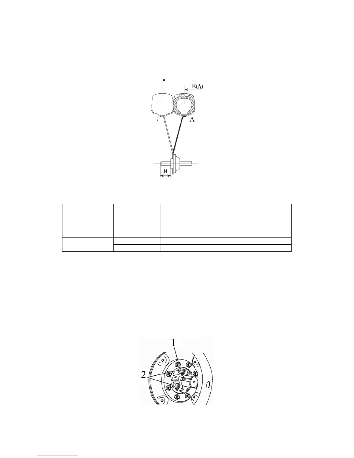
952.5-0000010 OM
82
3.2.9 Rear wheel track formation
3.2.9.1 Track formation of rear wheels, mounted on terminal hubs
The rear wheel track with the wheels of basic configuration 18.4R34 is changed by
moving the hub together with the wheel over the axle shaft and by replacing the wheels from
one sideboard to the other one as shown in figure 3.2.3.
Figure 3.2.3 – Variants of rear wheel track settings by replacing the wheels from one
sideboard to the other
Table 3.3 – Variant of rear wheel track setting (terminal hubs)
Tire size
Variant
(Figure 3.2.3)
“K” track dimen-
sions, mm
The installation dimen-
sion from the hub end
face to the axle shaft
end “H”, mm
А К(А) 1500…1600 50…0
18.4R34
B К(B) 1800…2100 164…14
ATTENTION: EX-WORKS DELIVERED REAR WHEELS ARE SET TO A TRACK UNDER THE
VARIANT A (FIGURE 3.2.3)!
To change the rear wheel track perform the following operations:
- put the tractor on a level ground, put the stops under the front and rear wheels, clean
the axle shafts from dirt;
- jack up the corresponding axle tube;
- undo the nuts 1 (Figure 3.2.4) attaching the wheels and remove the wheels;
- release four bolts 2 of the rear wheel hubs by 3 to 5 turns;
- move the hub to one or other side to obtain the required width;
- tighten the four bolts 2 attaching the hub with a torque of 300 to 400 Nm;
- mount the wheel and tighten the nuts 1 with a torque of 300 to 350 Nm;
- repeat the operations on the opposite wheel.
1 – nuts attaching the wheel to the hub; 2 – bolts attaching the hub to the axle shaft.
Figure 3.2.4 – Rear wheel track setting mounted on terminal hubs
Page 83
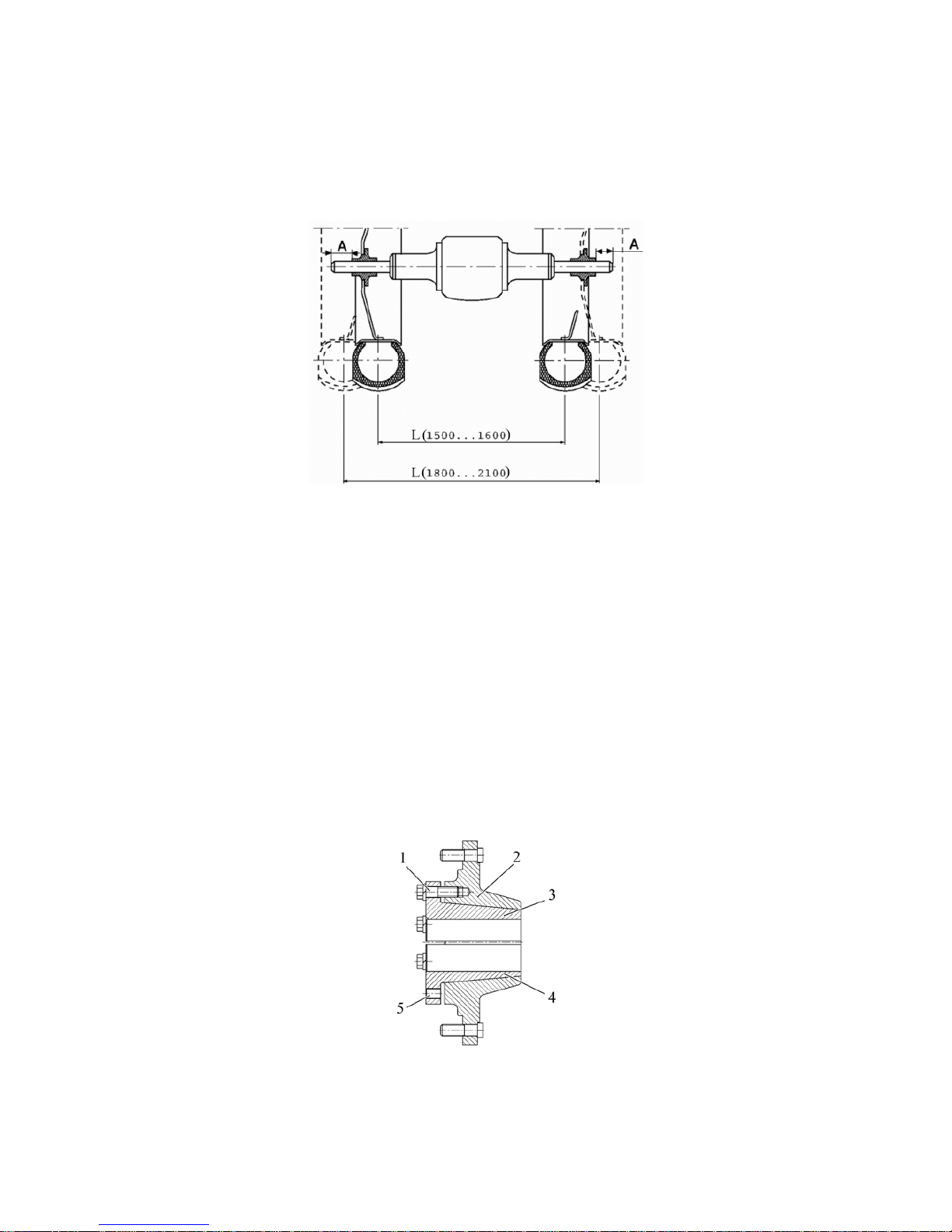
952.5-0000010 OM
83
Check tightening of the wheel attaching nuts and the hub attaching nuts after the
first hour of operation, after the first eight-ten hours of operation and every subsequent 125
hours of operation.
Use table 3.4 and figure 3.2.5 to define the track width by changing the distance “A”
from the axle shaft end to the hub face.
Figure 3.2.5 – Rear wheel track
Table 3.4 – Rear wheel track installation variants (terminal hubs)
Track width L, mm Distance “А”, mm
1440 80
1500 50
1600 0
1800 164
1900 114
2000 64
2100 14
3.2.9.2 Track formation of rear wheels, mounted on taper hubs
Against order rear wheels of the tractor can be mounted on taper hubs, that consists of divided taper pieces 3 and 4 (figure 3.2.6) and hub body 2.
The inserts are tightened into hub housing with six bolts 1 (M20) with a torque from
360 to 450 Nm and in such way they pressure the semi-axle.
1 – tie bolt; 2 – hub housing; 3 – upper insert; 4 – lower insert; 5 –holes for disassembly.
Figure 3.2.6 – Taper hub of rear wheel
Page 84
952.5-0000010 OM
84
The rear wheel track with the wheels of basic configuration 18.4R34 is changed by
moving the hub together with the wheel over the axle shaft and by replacing the wheels from
one sideboard to the other one.
To change the rear wheel track perform the following operations:
- put the tractor on a level ground, put the stops under the front and rear wheels, clean
the axle shafts from dirt;
- jack up the corresponding axle tube;
- loosen the wheel retaining nuts and remove the wheel;
- release by three full revolutions two tie bolts 1 (figure 3.2.6) of the inserts 3 and 4 (one
on each insert). The other bolts are to be screwed out. Remove blind plugs from the holes for
disassembly. Screw in the bolts of the inserts in the thread holes for disassembly;
- if it is impossible to squeeze the inserts out by means of disassembly bolts 1, fill kerosene or other liquid penetrant in places where inserts are detached from the hub body, wait for
some time and then screw the disassembly bolts in, simultaneously knocking on the hub body
until the inserts fully squeeze out;
- move the hub to a required track (use the table 3.5 to set the track “K” (figure 3.2.3) by
way of measuring the dimension “L” from the axle shaft end to the insert end face);
- screw the tie bolts out of the disassembly holes and screw them into the inserts.
Tighten the bolts with a torque of 360 to 450 N·m in several stages until all bolts are tightened
with the required torque;
- mount the wheel on the hub, tighten the wheel retaining nuts with a torque from 300 to
350 Nm, place back the blind plugs;
- set the track for the other wheel by analogy;
- check and tighten the tie bolts and wheel retaining nuts after the first operation hour,
then after the first eight – ten operation hours and after every consecutive 125 hours of operation.
ATTENTION: AFTER TIGHTENING THE BOLTS MAKE SURE THE END SURFACES OF
THE UPPER AND LOWER INSERTS DON’T JUT OUT WITH RESPECT TO EACH OTHER BY A
VALUE OF 1…2 MM!
Table 3.5 – Rear wheel track installation variants (taper hubs)
Standard size of
tires
Variant
(Figure 3.2.3)
Dimension of track
“K”, mm
Mounting dimension
from the hub end face to
the axle shaft end “H”,
mm
А К(А) 1500…1600 69…19
18.4R34
B К(B) 1800…2100 183…33
ATTENTION: EX-WORKS DELIVERED REAR WHEELS ARE SET TO A TRACK UNDER THE
VARIANT A (FIGURE 3.2.3)!
3.2.10 Rear wheel twinning
With an aim to improve gripping properties of the tractor when coupled with heavy
agricultural implements on soils with low bearing capacity, rear wheel twinning with use of
spacers is provided.
To receive information on the rules of rear wheel twinning and operating restrictions
for the tractors with rear wheels twinned, please, contact your dealer!
Page 85
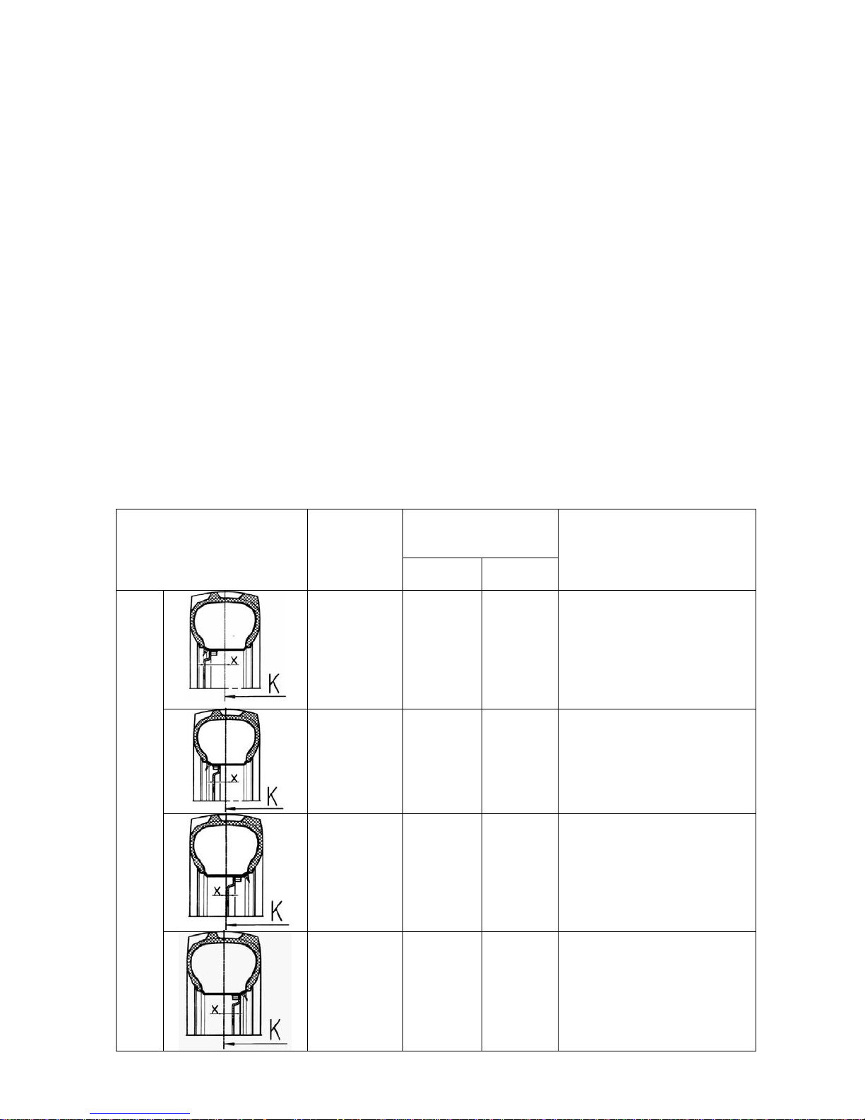
952.5-0000010 OM
85
3.2.11 Front wheel track formation
3.2.11.1 General information
On tractor BELARUS-952.5 equipped with RLL with hydraulic lift is mounted FDA with
planetary cylindrical wheel-hub drives (822-2300020-02 – with long beam, 822-2300020-04 –
with short beam).
On tractor equipped with RLL with draft control unit in basic configuration is mounted
FDA with planetary cylindrical-wheel hub drives with long beam or with short beam (8222300020-02 or 822-2300020-4). Optional the tractor BELARUS-952.5 can be equipped with draft
control unit, can be mounted FDA with taper wheel hubs (72-2300020-А-04).
Rules for front wheels track formation of the tractor with FDA with planetary cylindrical
wheel hub drives are given in clause 3.2.11.2.
Information of possible variants of front wheels track installation of the tractor BELARUS-
952.5 with FDA with taper wheel hubs and information about tires, mounted on tractor „BELARUS-952.5“ with FDA 72-2300020-А-04, are given in clause 3.2.11.3
3.2.11.2 Front wheels track formation of the tractors equipped with FDA with
planetary cylindrical wheel-hub drives
The front wheel track is adjusted stepwise both by displacing the wheels from one sideboard to the other, and by changing a position of the wheel disk relative to the rim.
The front wheel track may have the following dimensions: 1415, 1515, 1585, 1685,
1735, 1835, 1900, 2000 (for short beam), и 1535, 1635, 1705, 1805, 1855, 1955, 2020, 2120
(for long beam).
Installation diagrams and track dimensions for tires 360/70R24 (basic configuration for
tractor BELARUS-952.5 with FDA 822-2300020-02/04) are given in table 3.6.
Table 3.6 – Front wheel track adjustment for tractor with mounted FDA 822-2300020-02/04
Tractor track
К, mm
(tire 360/70R24)
Variants of mounting the
disk and the rim
Disk offset Х,
mm
Short
beam
Long
beam
Description of mounting
method
+140 1415 1535
Main position. The inner surface of the disk mates with
the gear group flange, and
the disk is located from the
outer side of the wheel support
+90 1515 1635
Ex-works condition.
The rim is displaced relating
to the disk. The inner surface
of the support mates with the
disk.
-18 1735 1855
The rim is turned by 180°.
The disk mates with the support inner surface.
Standard disk mounting with rim displacement
-68 1835 1955
The rim is turned by 180°.
The disk mates with the support outer surface.
Page 86
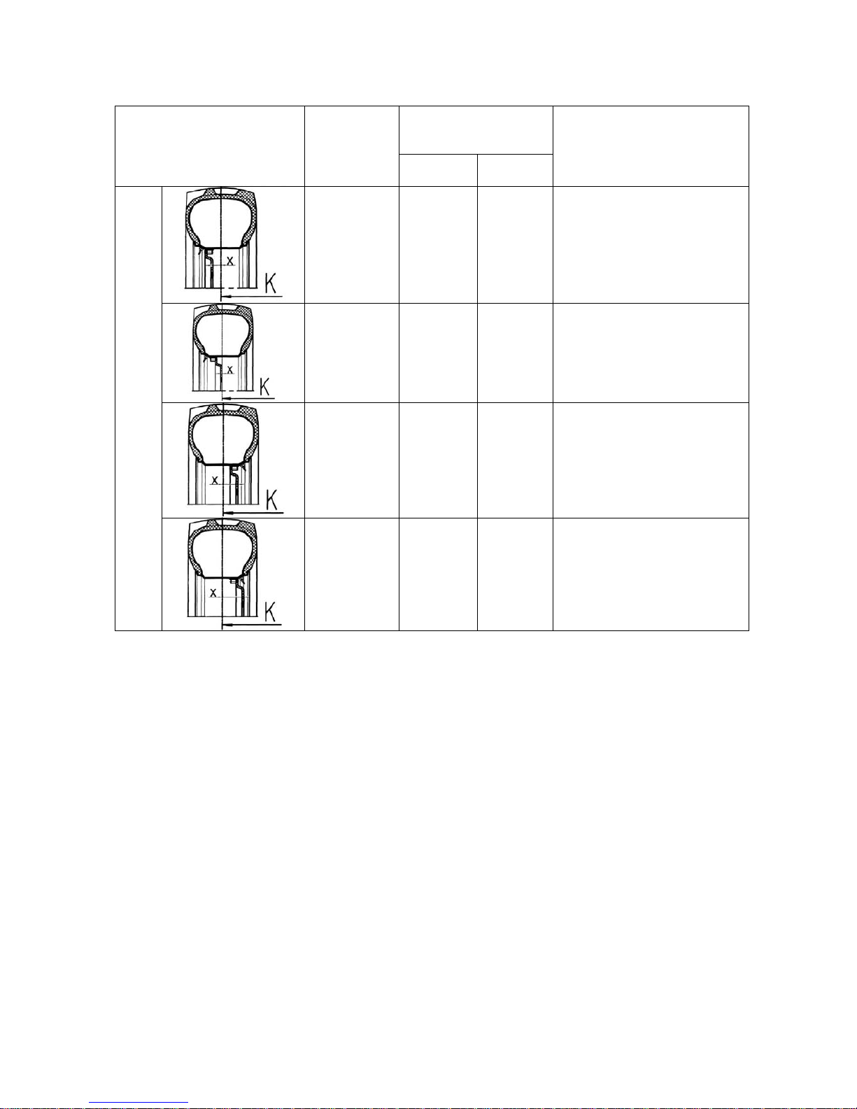
952.5-0000010 OM
86
End of table 3.6
Tractor track
К, mm
(tire 360/70R24)
Variants of mounting the
disk and the rim
Disk offset Х,
mm
Short
beam
Long
beam
Description of mounting
method
+56 1585 1705
The disk mates with the support outer surface.
+6 1685 1805
The disk mates with the support inner surface.
-102 1900 2020
The rim is turned by 180°.
The disk mates with the support inner surface.
Displacement of the disk and the rim
-152 2000 2120
The rim is turned by 180°.
The disk mates with the support outer surface.
To set a required track proceed as follows:
- brake the tractor using the parking brake. Put stop members at the front and at the
back of the rear wheels;
- jack up the tractor front part (or front wheels one by one), ensuring clearance between
the wheels and the ground;
- to obtain the track by displacing the wheel from one sideboard to the other one without
changing disk position with respect to the rim, unscrew the nuts fastening the wheel disk to the
gear group flange, take the wheels off and change from one sideboard to the other one,
- to obtain the track by changing disk position relative to the rim with the wheels taken
off the tractor, unscrew the nuts fastening the wheel rim to the disk and depending on the track
required, set mutual arrangement of the rim and the disk as shown in the diagram in table 3.6.
Mounting the wheels make sure the wheel rotation direction coincides with the direction
of an arrow on tire side.
The tightening torque for the nuts attaching plates to the gear group flanges shall make
200 to 250 Nm;
The tightening torque for the nuts attaching plates to the rim brackets shall make 180 to
240 Nm.
ATTENTION: AFTER YOU HAVE MOUNTED THE WHEELS CHECK NUTS FOR
TIGHTENING AFTER THE FIRST OPERATION HOUR, AFTER 10 OPERATION HOURS AND
EVERY 125 HOURS OF OPERATION!
ATTENTION: AFTER YOU HAVE CHANGED THE FRONT WHEEL TRACK CARRY OUT
CHECK AND ADJUSTMENT OF FRONT WHEEL TOE-IN. BEFORE CHECKING THE TOE-IN
MAKE SURE TO CHECK AND, IF NECESSARY, ADJUST PLAY IN STEERING JOINTS!
Page 87
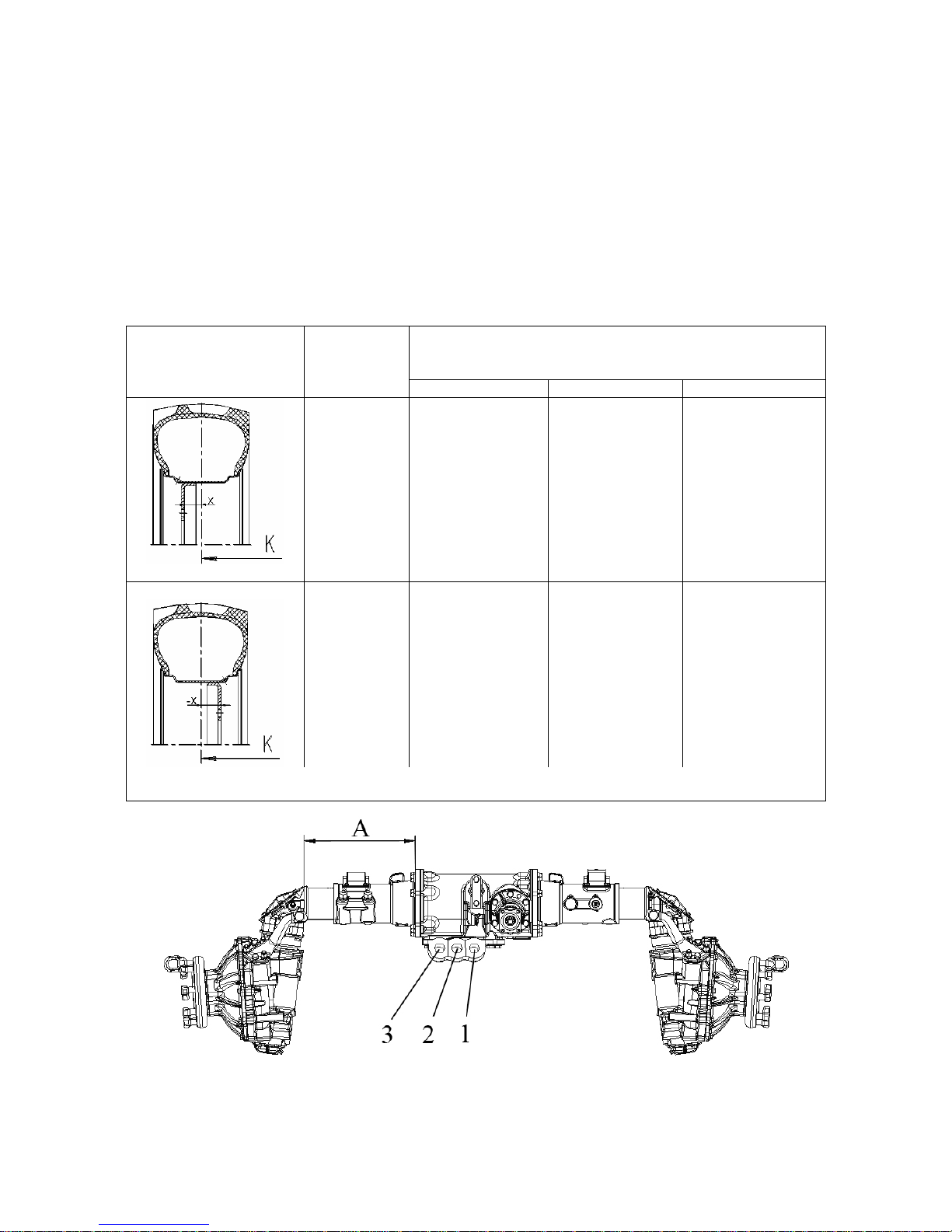
952.5-0000010 OM
87
3.2.11.3 Possible variants of front wheels track installation of the tractors,
equipped with FDA with taper wheel hubs and information on tires, mounted on tractors with FDA 72-2300020-А-04.
The track of the tractor equipped with FDA taper wheel-hub drives is changed stepwise
depending on the size of moving-out of wheel-hub drives (size A in figure 3.2.7) and correspondingly on the hole for fastening of HSC cylinder (holes 1, 2, 3 as shown in figure 3.2.7), the wheel
track may have the following dimensions 1420, 1530 and 1640 mm, and by displacing the wheels
from one side board to the other – 1720, 1830, 1940 mm (with 13.6-20 front tires mounted).
Installation diagrams and track dimensions for tires 13.6-20 (basic configuration for tractor
BELARUS-952.5 with FDA72-2300020-А-04 ) are given in table 3.7.
Table 3.7 – Front wheels track formation with FDA 72-2300020-А-04 mounted
Tractor track К, mm (tire 13.6-20)
(while fastening the HSC cylinder in holes 1, 2, 3
(figure 3.2.7))
Wheels installation
diagram
Disk offset Х,
mm
hole 1 hole 2 hole 3
+70
1420
(Size А=270)
1530
1)
(Size А=325)
1640
(Size А =380)
-80
1720
(Size А=270)
1830
(Size А=325)
1940
(Size А =380)
__________________________________________________________________________________________
1)
EXW condition
Figure 3.2.7 – Scheme of front wheels track change of the tractor with
FDA 72-2300020-А-04
To receive information on the rules of front wheel track changing with mounted
FDA72-2300020-А-04 please contact your dealer.
Page 88

952.5-0000010 OM
88
The tractor BELARUS-952.5 in basic configuration with FDA 72-2300020-А-04 is
equipped with the following tires:
- front wheel tires – 13.6-20;
- rear wheel tires – 16.9R38.
The velocity diagram table of “BELARUS-952.5” tractor equipped on tires of basic
configuration 16.9R38 is attached to the cab right window
Rates of loads on tractor single tires 13.6-20 and 16.9R38 for selection of operational
modes at various speeds and tire inner pressures in tires are given in table 3.8.
Table 3.8
Load on tire, kg,
a inner pressure, kPa Tire
Load
index**
Speed
symbol
**
Speed,
km/h
80 100 120 140 160
13.6-20 120 A8
10*
20
30
40
1530
1250
1090
1020
1650
1350
1175
1100
1800
1475
1280
1200
1950
1595
1390
1300
2100
1720
1495
1400
16.9R38 141 A8
10*
20
30
40
2550
2090
1815
1700
2880
2360
2050
1920
3210
2630
2285
2140
3530
2895
2515
2355
3860
3165
2755
2575
* - inner pressure shall be increased by 25 %
** Load index and speed symbol (see on tire sidewall).
Rates of loads are provided for tires with indicated load index and speed symbol.
Pressure shall be set in “cold” tires.
Performing operations, requiring large pulling force on the hook, set the pressure as
for the speed of 30 km/h. When performing transport operations on roads with solid surface increase the pressure by 30 kPa.
Total loading capacity of twinned tires shall not exceed the loading capacity of a
single tire by more than 1,7 times;
When twinning, make sure the pressure of outer tires is 1,2 – 1,25 times lower, than
the pressure of inner tires.
For the tractors BELARUS-952.5 with FDA 72-2300020-А-04 besides tires 13.6-20 and
16.9R38 the other tires can be used, including narrow tires for operations in spaces between rows. To receive information on tires, provided for kitting of the BELARUS-952.5
tractors with FDA 72-2300020-А-04, please contact your dealer. Your dealer will also provide your with information on the rules of front and rear wheels track changing, will inform
rolling radius of the rear wheel tire for setting of the “R” parameter of integrated indicator,
will specify tires load rates for selection of operational modes at various speeds and tire inner
pressures, will send you information on speeds of the tractor with this tires.
Page 89

952.5-0000010 OM
89
3.3 Safety measures to be taken when operating the tractor
3.3.1 General safety measures to be taken when operating the tractor
The cab complies with category 2 under EN 15695-1:2009. This category cab ensures protection against dust, but not against sprays and vapor – the tractor shall not be
used under conditions, requiring protection against sprays and vapor.
Do not operate the tractor in a closed room without required ventilation. Exhaust
gas may result in lethal outcome.
Tractor start-up and operation with the hood opened is not allowed.
It is forbidden to open the hood when the engine is running.
Do not start the engine when staying outside the operator's seat. Starting the engine and manipulating the controls, always stay inside the cab in the operator's seat.
Do not start the engine by way of towing.
Before starting the engine, engage the parking brake, the rear PTO shall be disengaged, the range shifting lever shall be in “Neutral” position.
During tractor start there shall be no people under the tractor, in front of it or behind,
as well as between the tractor and the coupled implement or trailer.
Before setting on the move warn people around including those operating the coupled implements using the horn, make sure the parking brake is off and start moving
slowly.
Use safety harnesses (supplied against order) at hauling operations.
Passenger staying in the cab during tractor operation is strictly forbidden. (Passenger may stay in the cab only when an additional seat is installed and hauling operations
are carried out).
Do not leave the tractor on the move.
Performing hauling operations observe traffic regulations, adopted in your country.
Hauling operations may be carried out by operators with not less than two years of
tractor operation experience and those who have passed exams in traffic regulations.
Drive the tractor on slippery roads with automatic DL (if mounted) engaged only at a
speed not higher than 10 km/h.
Using the tractor for hauling operations do the following:
- set a track (1530±20) for front wheels and (1800±20) for rear wheels mm.
- check operation of brakes; interlock brake pedals, check and if necessary adjust
the brakes for simultaneity of operation;
- check operation of the parking brake;
- check a condition of devices for light and sound annunciation; hauling trailers shall
have rigid hitches and be linked with a safety chain or a cable;
- never move downhill with the gear disengaged. Move uphill and downhill at the
same gear;
It is forbidden to operate with a trailer without independent brakes, if its weight exceeds a half of a total actual weight of the tractor. The faster you move and the more
weight you tow, the bigger safety distance shall be.
It is forbidden to drive the tractor with twinned wheels on public roads!
Hauling people inside trailers is forbidden.
Before getting down to work with a trailer turn the compressor on, check the condition of the trailer brake pneumatic drive and air pressure in the system. Remove the failures detected. Make sure to connect the trailer brake pneumatic drive. Carry out connection of the trailer connecting head to the tractor connecting head with the parking brake
engaged.
Page 90

952.5-0000010 OM
90
Do not work under raised agricultural implements. Do not leave implements uplifted
when stopping for a long time.
Trailers attached to the tractor shall have a braking system, ensuring:
- trailer brake on movement;
- brake engagement in case of trailer detachment from the tractor;
- holding the trailer when staying on slopes;
- prevention of trailer from pushing the tractor when the travel speed is changed
abruptly.
The trailer shall be linked to the tractor by means of a safety chain.
It is required to check operation of the braking system of tractor-trailer train at a
speed of 3 to 5 km/h.
The travel speed at access ways and at pass ways shall not exceed 10 km/h.
Loading (unloading) the trailer engage the parking brake of the tractor.
Driving on public roads turn on a flashing beacon, if available.
Do not stop the tractor on slopes. If there is a necessity to stop the tractor engage
the parking brake.
Working on the slopes increase the tractor track to the max.
Working on the slopes with an angle of more than 20° set the max. rear wheel track.
Before exiting the cab disengage the rear PTO, stop the engine, engage the parking
brake and remove the key from the starter switch.
If the engine or the steering are broken down, immediately stop the tractor. Keep in
mind that with the engine stopped it is required to apply much greater force to the steering
wheel to operate the tractor.
In case a failure occurs, immediately stop the tractor and eliminate the fault.
Avoid leakage of electrolyte, coolant, fuel, oil and braking fluid.
Use summer and winter grades of fuel correctly. Fill in the fuel tank at the end of
each day to decrease night condensation of moisture. Fill the tractor only with grades of oil
and lubricants recommended by the manufacturer. It is strictly forbidden to use other lubricants.
It is forbidden to turn off the system of electrical equipment by means of the battery
disconnect switch with the engine running.
Operate the tractor at night-time with lighting devices on and being in good order.
If put to a wrong use, your tractor can be dangerous for you as well as for third persons. Avoid using equipment not intended for installation on the tractor.
Make sure any additional equipment or auxiliary units are mounted correctly and
that they are intended to be used with your tractor.
To prevent the tractor from turning over, keep up with the following precaution
measures when operating the tractor:
- choose safe speed, corresponding to road conditions, especially when moving
cross-country, when crossing ditches, slopes and by sharp turns;
- turn round corners with a speed not higher than 5 km/h, on a slippery road – not
higher than 3 km/h.
- move down the hill with first or second gear engaged.
Note – This list of precaution measures is not exhaustive. To avoid turning over, be
always careful when operating the tractor.
It is forbidden to use the tractor at works where there is a possibility for the tractor to
turn over.
Page 91

952.5-0000010 OM
91
Do not operate the tractor with gauges out of order.
It is not admitted to inflate tires without pressure control.
Coupling the tractor with agricultural implements comply additionally with safety
measures concerning use of these implements.
Before coupling the tractor with agricultural implements make sure the automatic
grips of the lower and upper links of the RLL are clean and faultless. It is forbidden to operate with the automatic grips out of order, their inner cavities stuffed with dirt and foreign
particles.
If the tractor front part rises off the ground when heavy implements are hinged on
the mechanism of the rear lift linkage, mount front ballast weights.
Do not work under raised agricultural implements. Do not leave implements uplifted
when stopping for a long time.
Before lifting and lowering a hinged agricultural implement and also when turning
the tractor make sure there is no danger of catching somebody or stumbling on the hurdle.
The mounted and semi-mounted machine is to be lowered into its operating position
and up lifted into the hauling position only with a straight-line motion of the assembly unit.
To avoid breakdown of the tractor or the agricultural implement, drive and turn the
tractor assembly with the agricultural implement uplifted only after you make sure the rear
PTO are disengaged.
Linking and hinging the agricultural machines and implements on the tractor the
rear operator shall stay at a safety distance until the operation is fully stopped. The linkage
(hinge) shall be started only after the tractor operator gives a command.
Linking the machine cardan shaft to the RPTO, disengage the RPTO, stop the tractor by means of the parking brake and stop the engine.
After disconnecting the machines driven by the RPTO, remove cardan drives and
cover the PTO end extensions with protective caps.
Cardan shafts, transferring torque from the RPTO of the tractor to the implement
working units shall be safeguarded.
Operating with stationary machines, driven by the RPTO, always engage the parking brake and lock the rear wheels at the front and at the back. Make sure the machine is
securely fixed.
Make sure the safeguards of the RPTO is mounted and, if the PTO is not used, put
back the cap of the PTO shaft end extension.
Do not wear loose clothes when working with the RPTO or near rotating equipment.
To avoid breakdown of the tractor or the agricultural machine, turning the tractor assembly is possible only after the working units of the machine have been fully raised from
the ground.
When the tractor assemblies are operating in a column, they shall have an interval
not less than 30 m between each other.
Depending on operation conditions use natural ventilation of the cab or the unit of
air cooling and heating.
During tractor operation the operator shall use standard means of protection for hearing
organs.
In case the tractor assembly is operated or is driven in an area of power transmission lines, a distance between the top of the tractor assembly and wires shall conform to
table 3.9.
Table 3.9
Line voltage, кV, up to
11 20-25 110 154-220 330-500
Horizontal distance, m, not less than
1,5 2 4 6 9
Vertical distance, m, not less than 1 2 3 4 6
Page 92

952.5-0000010 OM
92
3.3.2 Fire safety measures
The tractor shall be equipped with fire fighting equipment, i.e. a shovel and a
fire extinguisher. Operating the tractor without fire fighting equipment is forbidden.
Never fuel the tractor with the engine running.
Do not smoke when fueling in the tractor.
Do not fuel the tank to the max. Leave some volume for fuel to expand.
Never add petrol or mixtures to engine fuel. This combination may create increased
danger of inflammation or explosion.
Places for tractor parking, storing of fuel and lubricants shall have a plowed around
band of not less than 3 m width and also be provided with fire extinguishing means.
The tractor must be filled with fuel and lubricants by a mechanic way and with the
engine stopped. Use lighting at night time. It is not recommended to fill in tanks using
buckets. Carrying out repair operations in field conditions using electric/gas welding, clean
parts and assembly units from plant remains.
Prevent the manifold and muffler from getting dirty with fuel, thatch, etc.
Avoid thatch winding around rotating parts of the implements coupled with the tractor.
Washing parts and assembly units with kerosene or gasoline take care to exclude a
possibility of inflammation of flushing fluid vapor.
Do not operate the tractor in places subjected to fire risk with the hood and other
protective units removed from hot parts of the engine.
Do not use open fire to warm up oil in the engine sump, to fill in fuel tanks, to burn
out dirt in a radiator cell.
In case a fire bed occurs, pour some sand onto it, cover with canvas cloth, sackcloth or other dense texture. Use a dry-powder fire extinguisher. Do not pour water over
burning fuel and oil.
Make sure there are no flammable materials near the exhaust manifold and the
muffler during engine running.
Harvesting hay and thatch, operating at places with enhanced danger of fire, avoid
amassment of inflammable materials on a muffler guard and on gas links.
Performing daily maintenance be sure to do the following operations:
- check the condition of the wiring, wire bundles in the engine compartment, in the
cab front area, and the condition of visible parts for abrasion, melt or damage of outer insulation. Should the above faults be discovered, restore the damaged areas using insulation tape and eliminate the cause that has lead to insulation damage;
- review the hydraulic components. If there is steaming and leakage, it shall be
eliminated by way of tightening of threaded connections. Faulty high-pressure hoses and
pipes shall be replaced.
To avoid burning of tractor wiring never use fuses with current rating higher than rat-
ing specified in this subsection 2.21 “Cutout fuses”.
It is forbidden to mount wire bridges and other current-conductive components,
manufactured by rule of thumb instead of cutout fuses.
Turn the power disconnect switch off when finishing to operate the tractor.
Page 93

952.5-0000010 OM
93
3.4 Tractor final assembly and run-in
3.4.1 Tractor final assembly
The “BELARUS-952.5” tractors are supplied to a consumer ready assembled, final assembly is not required.
3.4.2 Technical maintenance before tractor run-in
Before placing a new tractor in operation do the following:
- wash the tractor, remove preservative lubricant (if any on the tractor);
- carefully inspect the tractor, check it for completeness and availability of instruction
manuals;
- remove accumulator battery, set it into working condition and mount back;
- check outer threaded joints for tightness and tighten if necessary;
- check oil level in the engine oil sump, in the transmission, in FDA case, intermediate bearing of FDA cardan drive, in cases of FDA wheel gear groups (on tractors with FDA
72-2300020-А-04 in upper and lower bevel gear and pinion group of FDA wheel hub-drives),
in HLL and HSC oil tanks and, if necessary, add as per section 5 “Maintenance”;
- drain the available fuel from the fuel tank and fill the fuel tank with new settled fuel:
in winter – winter grade, in summer – summer grade;
- fill the engine cooling system with coolant up the upper edge of the radiator filler
neck, fill the expansion tank with coolant till it occupies half of the tank volume.
- check and if necessary adjust the tire pressure to a desired value in accordance
with subsection “Selection of optimal inner pressure in tires depending on operational conditions and load on tractor axles”.
- make sure there are protective guard shields (for RPTO etc.);
- check engine running, operability of lighting and warning devices, action of brakes
and steering control, and also check functioning of the other systems and units of the tractor over on-board control gauges;
Before starting to run in, check tightness of bolts attaching the hubs (the tightening
torque for the bolts attaching terminal hubs of rear wheels shall make 300 to 400 Nm, the
tightening torque for the bolts attaching taper hubs shall make 360 to 400 Nm), tightness
of the nuts attaching rear wheels to the hub (the tightening torque shall make 300 to 350
Nm), the nuts attaching front wheel plates to FDA gear group flanges (the tightening
torque shall make 200 to 250 Nm), on tractors with FDA 822-2300020-02/04 (basic configuration) tightness of the nuts attaching front wheel plates to rim brackets (the tightening
torque shall make 180 to 240 N·m).
3.4.3 Tractor run-in
ATTENTION: THE FIRST 30 HOURS OF TRACTOR OPERATION HAVE GREAT
INFLUENCE ON OPERATIONAL PARAMETERS AND LIFE SPAN OF THE TRACTOR.
YOUR TRACTOR WILL FUNCTION PROPERLY FOR A LONG TIME PROVIDING YOU
CARRY OUT THE RUN-IN CORRECTLY AND PERFORM OPERATIONS IN TECHNICAL
MAINTENANCE IN TERMS SPECIFIED IN SECTION 5 “MAINTENANCE”!
ATTENTION: IT IS OBLIGATORY THAT YOU CARRY OUT TRACTOR RUN-IN
FOR 30 HOURS! LOAD THE TRACTOR UP TO 80 % OF ITS RATED POWER BEFORE
THE FIRST TECHNICAL MAINTENANCE (TM-1) (125 HOURS)!
Page 94

952.5-0000010 OM
94
Start the engine. Let the engine run at idle speed for five minutes with gradual increase of the rotation speed up to 1600 rpm, then run in under the load for 30 operation
hours.
Carrying out the 30-hour run-in follow the below instructions:
- constantly inspect gauge indications, operation of lubrication system, cooling sys-
tem and power supply system. Control levels of oil and fluids in refill capacities;
- check outer fastening links for tightness and tighten them;
- do not overload the engine, avoid engine smoking and speed decrease. The features of overload are sharp decrease of speed, smoking and absence of engine reaction to
increase of fuel feed. Operation at high gear under load results in excessive wear of friction parts of the engine;
- tractor operation at lower gear under small load and with increased speed of the
engine will result in fuel overconsumption. Right selection of the gear for each specific
condition of operation ensures fuel economy and reduces engine wear-out;
- avoid prolonged engine operation without load in a mode of max. or min. speed of
the engine;
- for correct break-in of the clutch friction parts during the run-in process engage the
clutch more often and more smoothly.
3.4.4 Technical maintenance during tractor run-in
After the first operation hour check tightening of nuts attaching rear wheels to the
hub, nuts attaching front wheels to FDA gear group flanges. If FDA 822-2300020-02/04
(basic configuration) is mounted, please check tightening of nuts attaching the front wheel
disks to the rim brackets. Then inspect the wheel tightening every eight hours during the
run-in.
In the run-in process regularly carry out operations in shift-time technical maintenance according to the instructions, set forth in section 5 “Maintenance” of this manual.
3.4.5 Technical maintenance after tractor run-in
After the tractor run-in do the following:
- perform shift-time maintenance operations;
- inspect and wash the tractor, clean the cab;
- listen to the operation of all tractor constituents;
- check tightening of nuts attaching rear wheels to the hub, nuts attaching front
wheels to FDA gear group flanges and nuts attaching the front wheel disks to the rim
brackets;
- tighten two lock nuts M27x1,5 (with left and right thread) of the steering link tube
with a torque of 100 to 140 N·m and two crown nuts M20x1,5 of the steering link ball pins.
To tighten the crown nuts, remove the cotter pin first, tighten each crown nut with a torque
of 100 to 140 N·m, then turn each crown nut until the nearest notch on the nut coincides
with a hole in the ball pin and then fasten with a cotter pin.
- check and if necessary tighten outer threaded links;
- drain condensate from the pneumatic system receivers;
- drain sediment from fuel tanks and the engine coarse filter;
- check the state of accumulator batteries, clean terminal connections and ventilation holes;
- check and if required adjust free movement of the clutch pedal, of the working and
parking brakes control and brake valve drive of pneumatic system;
- change oil in transmission;
- on tractors with FDA822-2300020-02/04 (basic configuration) change oil in housings of wheel hub drives, FDA case and intermediate bearing of FDA cardan drive.
- on tractors with FDA 72-2300020-А-04 change oil in upper and lower bevel gear
and pinion groups of FDA wheel hub drives, FDA case and intermediate bearing of FDA cardan drive.
- replace oil in the engine crankcase;
- replace oil filter of the engine;
Page 95

952.5-0000010 OM
95
- check and if required tighten the bolts attaching cylinder heads;
- check and if required adjust clearance between the valves and rockers arms;
- check lubrication in all assembly units according to clause 3 of table 5.4. Where
required lubricate or replace the lubricant;
- check and if necessary restore hermiticity of the air cleaner and inlet line;
- control engine running, steering, brakes, operation controls, lighting and warning
systems;
3.5 Emergency actions
3.5.1 To stop the tractor immediately, sharply depress clutch and brake pedals.
3.5.2 For emergency stop of the engine turn the key of the starter and instrument
switch from “I” position to “0” position according to the diagram provided in figure 2.2.2.
3.5.3. In case of an accident immediately stop the engine, engage tractor brakes, deactivate accumulator batteries and get off the tractor through one of emergency exits, having
opened left or right cab door, depending on the tractor position, or rear screen, or the roof.
If it is not possible to open the emergency exits, break front or rear screen, or one of the
lateral screens with a heavy subject at hand and leave the tractor cab.
Note – Emergency exit allocation is given in subsection 2.22 “Cab locks and handles”.
3.5.4 In case the engine crankshaft speeds up excessively, kill the engine and brake the
tractor immediately.
3.5.5 In case a fire bed occurs, stop the engine, brake the tractor, turn off the accumulator
battery switch. Pour some sand onto the fire bed, cover with canvas cloth, sackcloth or
other dense texture. Use a carbon-dioxide fire extinguisher. Do not pour water over burning fuel and oil.
Page 96

952.5-0000010 OM
96
4 COUPLING OF IMPLEMENTS
4.1 General information
In section 4 "Coupling of implements" necessary instructions and data on features of
application of tractor “BELARUS -952.5” are given.
Permitted field of application of tractor “BELARUS-952.5” includes places with unre-
stricted air exchange, sufficient flotation and overall passing ability.
Tractors “BELARUS-952.5” are designed for performance of the mechanized works in
plant growing and fodder production.
Tractors “BELARUS-952.5” are packaged with necessary work equipment for coupling of
implements i.e. lift linkage and drawbar hitches, PTO, hydraulic feed-outs, pneumatic heads and
electrical outlet receptacles. The tractor implements listed above allow coupling of implements of
various machines in structure of MTU (machine and tractor unit or tractor-mounted units).
ATTENTION: TRACTORS “BELARUS-952.5” ARE DESIGNED FOR COUPLING OF
MOUNTED, SEMI-MOUNTED, SEMI-TRAILED AND TRAILED IMPLEMENTS IN STRUCTURE
OF МТU ONLY, TECHNICAL CHARACTERISTICS OF WHICH, RELATED TO ABILITY TO BE
COUPLED, ARE COMPARABLE TO TRACTOR SPECIFICATIONS! OTHER APPLICATION OF
TRACTOR IS NOT ALLOWED!
Selection and buying of agricultural implements (fertilizer distributors, plungers, motor cultivators, harrows, seeding machines, rotary tooling and other implements) for tractors “BELARUS-
952.5” is carried out by the customer itself according to its needs, and with consideration of the implement and tractor performance specifications, and also local conditions i.e. agrotechnical requirements, soil conditions, personal experience, guidelines of corresponding regional advisory centers
and institutions for agricultural industry.
ATTENTION: GUIDELINES AND DATA ON SPECIFIC ASPECTS OF USAGE OF IMPLEMENTS WITH A TRACTOR AND DATA ON THE RECOMMENDED TRACTOR PERFORMANCE
SPECIFICATIONS ARE PRESENTED IN OPERATIONAL DOCUMENTATION FOR IMPLEMENTS COUPLED!
Possibilities of agricultural tractors applications in the specified use environment are limited
by tolerance range of force, exerted on hook rating and engine power, tractor maximum permissible
load, roadhold of chassis, frictional sliding, operation driving speed, size power take-off value and
operating weight of the implements coupled.
ATTENTION: WHILE OPERATING TRACTOR IN STRUCTURE OF МТU IT IS REQUIRED TO STUDY AND FOLLOW THE INSTRUCTIONS SET FORTH IN THE OPERATIONAL DOCUMENTATION OF IMPLEMENTS COUPLED WITH A TRACTOR CAREFULLY!
PERSONNEL NOT HAVING STUDIED DOCUMENTATION AND SAFE MACHINE OPERATING PROCEDURES, AND HAVING NO DOCUMENTS ON-SITE, IS NOT ALLOWED!
ATTENTION: WHEN COUPLING OF MOUNTED, SEMI-MOUNTED, SEMI-TRAILED AND
TRAILED IMPLEMENTS WITH TRACTORS “BELARUS-952.5”, INSTALLATION OF AUTOMATED CONTROL SYSTEMS, BEING THE PART OF THE MACHINE KIT, FOR TRACING
OF OPERATIONS SEQUENCE IN THE CABIN, AND ITS CONNECTION TO THE BOARD
NETWORK IS ALLOWED IF IT IS PROVIDED FOR IN THE OPERATIONAL DOCUMENTS
FOR THE IMPLEMENTS.
Tractors “BELARUS-952.5” belong to the category of motor vehicles covered by traffic
regulations proceedings and other regulatory documents on the operation of off-track vehicles.
Tractor operator is personally liable for abidance by traffic regulations and safe operation requirements, and safety measures and correctness of tractor “BELARUS-952.5” operation, set forth in this operation manual.
Page 97

952.5-0000010 OM
97
Service stuff qualification requirements for tractor “BELARUS-952.5” operation:
- only qualified personnel that is aware of safety arrangement and precautions matters, having license documents of due form, determined by the legislation for tractor driving
and having got admission to operate certain tractor, is allowed.
- if tractor owner (or any person liable for tractor operation) does not operates tractor
himself, he must ensure that before starting operations all persons related to the tractor
have been duly instructed on safety operation requirements and on correct coupling of implements with the tractor, and have studied the operation manual for the tractor enclosed.
ATTENTION: OWNERS AND OFFICIALS OR OTHER PERSONS MUST NOT ALLOW THE TRACTOR FOR ROAD TRAFFIC AND COUPLING WITH IMPLEMENTS, OR
ADMIT OPERATORS FOR DRIVING THE TRACTOR IN CONTRAVENTION OF CURRENT TRAFFIC REGULATIONS AND THE PRESENT OPERATION MANUAL!
ATTENTION: BEFORE STARTING THE TRACTOR IN STRUCTURE OF MTU ENSURE THAT THERE IS NO PEOPLE IN CLOSE VICINITY TO THE TRACTOR INCLUDING
THE AREA BETWEEN THE TRACTOR AND IMPLEMENTS OR TRAILERS (SEMITRAILERS) COUPLED!
4.2 Types of implements coupled with tractor “BELARUS-952.5”
According to the type of coupling with tractors «BELARUS-952.5» the implements
are divided into the following types:
- mounted implement is fixed in three points to the upper and lower draft arms of LL.
The tractor can carry weight of an implement in full. Implement structural components at
carry is not in touch with ground contact area. While changing the implement position from
operating to transport the point in which the implement is connected to the tractor is forcedly
displaced to the new point along the full vertical extent;
- semi-mounted implement is fixed in three points to the upper and lower draft arms of
LL or just in two points to the upper and lower draft arms of LL only. The tractor can carry
weight of an implement in part and mostly by its traveling wheels (usually by one or two wheels).
While changing the implement position from operating to transport, the point in which the implement is connected to the tractor is forcedly displaced to the new point along the full vertical
extent. Two-point articulated linkage is effected by way of connection of suspension axis link pin to
the lower draft arms hinges of LL (upper draft arm is not used). It is also possible to use a cross
arm from the tractor or implement kit.
- semi-trailed implement is usually fixed in one point by means of tractor drawbar clevis
to the DH. It is also possible to use a two-point connection with lift linkage (upper draft arm is not
used). The tractor can carry weight of an implement in part and mostly by its traveling wheels
(usually not less than by two). While changing the implement position from operating to transport, position of the point in which the implement is connected to the tractor remains unchanged. Semi-trailed implements include various vehicles for general and special purposes: general purpose semi-trailers, tank semi-trailers and dampers, and special purpose semi-trailed vehicles for mechanizing of technological process in the agricultural sector.
- trailed implement is usually fixed in one point by means of tractor drawbar clevis to
the DH. It is also possible to use a two-point connection with lift linkage (upper draft arm is not
used). The chassis can carry weight of an implement in full, hitch mechanism (DH or LL) is
loaded only by weight of implement connector. While changing the implement position from
operating to transport, position of the point in which the implement is connected to the tractor
remains unchanged. Semi-trailed implements include various vehicles for general and special purposes: general purpose semi-trailers, tank semi-trailers, and dampers, and special purpose semitrailed vehicles for mechanizing of technological process in the agricultural sector.
Page 98

952.5-0000010 OM
98
4.3 Rear lift linkage
4.3.1 General information
ATTENTION: BEFORE LEAVING THE TRACTOR FOR ANY TIME PERIOD, THE
LINKED IMPLEMENT SHALL BE PUT ON THE GROUND INDISPENSABLY!
ATTENTION: MAXIMUM LIFTING POWER VALUE OF LIFT LINKAGE AT THE SUSPENSION AXIS DETERMINATES TECHNICAL OPERABILITY OF THE LIFT LINKAGE,
BUT NOT PERMISSIBLE MASS OF THE IMPLEMENT COUPLED THROUGH IT. PERMISSIBLE MASS OF THE IMPLEMENT DEPENDS ON THE CENTROID OVERHANGING
LENGTH AGAINST THE SUSPENSION AXIS, AND IT IS LIMITED BY PERMISSIBLE
LOADS ON THE TRACTOR AND BY CONTROLLABILITY CRITERION!
Rear lift linkage corresponds to the requirements of ISO 4254-3.
4.3.2 Three-point rear lift linkage
Three-point rear lift linkage of “BELARUS-952.5” is made according to State Standard GOST 10677 and ISO 730. Basic parameters of RLL, specified in Table 4.1 and in
Figure 4.3.1 and 4.3.2, parameters are given with standard rear tires (18.4R34 both single
and doubled), mounted to the tractor and with standard static radius, specified by the
manufacturer.
Rear lift linkage consists of three links (upper one and two lower links) with front
ends articulated via hinged joint with the tractor, and with rear ends articulated with free
hinged joint for the purpose of connection to the attachment pins of the implements coupled. RLL is designed for connection of implements for tail positioning to a tractor, for link
power transfer during operation and adjustment of their position during operation, or run at
transport position. RLL provides for coupling of the following types of implements and in-
struments:
- mounted implement fixed in three points (upper one and lower links);
- semi-mounted (lower links);
- semi-mounted with a cross arm to the suspension axis of lower links.
ATTENTION: MOUNTING OF A CROSS ARM OR TRAILING SUSPENSION AXIS,
BEING THE PART OF IMPLEMENTS SET FOR COUPLING OF SEMI-MOUNTED, SEMITRAILED AND TRAILED IMPLEMENTS FOR FULFILLMENT OF DIFFERENT WORKS
WHEN SPEED DOES NOT EXCEEDS 15 KM/H, TO THE ENDS OF LOWER LINKS OF
REAR LIFT LINKAGE!
Sizes and structure of RLL of tractors “BELARUS-952.5” make it possible to couple
all implements, having the corresponding dimensions of attachment elements of connection triangle shown in RLL diagram
Rear lift linkage diagram of type LL-2 with hydraulic lift is shown in Figure 4.3.1.
Rear lift linkage diagram of type LL-2 with draft control unit is shown in figure 4.3.2.
For protection of coupled implements from rocking length adjustable limit buckles
are used.
Page 99

952.5-0000010 OM
99
To ensure the implement is in the right position the following adjustments of RLL by means
of upper link, crossbars and limit buckles are provided in vertical and horizontal plane:
1 Modification of length of upper link
It is carried out in order to ensure penetration of operative parts (alignment of running depth of operative parts located one after another along the tractor run). If mounted
plough carriage reaches forward along the tractor run and the front plough body cuts
deeper than the rear one, extend the upper link; and if the front plough body cuts for the
more shallow depth than the rear one, the upper link shall be shortened.
2 Modification of length of left or right lifting rods.
The modification is carried out in the following cases:
- to ensure the implement is in the horizontal plane;
- to ensure the even depth processing with operative parts of tractor-mounted ma-
chine across the width of cut;
3 Modification of length of both lifting rods, upper link for transport position of the
implement.
The modification is carried out in the following cases:
- to ensure the necessary road clearance;
- to ensure the sufficient safe clearance between the elements of the tractor and the
implement, excluding the contact of parts of the tractor implements (clearance is not less than
100 mm).
4. Modification of length of both buckles.
The modification is carried out in the following cases:
- during transportation of the implement, buckles shall be blocked for the limitation
of the implement rocking at run for the avoidance of the tractor elements damaging in case
of an incidence;
- during operation of mounted, semi-mounted tilling machines with passively operated parts for the full processing (share and chisel ploughs, shallow ploughs, rippers and
other implements), free movement in horizontal plane (rocking) shall be ensured, and the
buckles shall be partial blocked.
IT IS FORBIDDEN TO OFFSET THE LONGITUDINAL AXIS OF THE IMPLEMENT,
CONCERNING THE LONGITUDINAL AXIS OF THE TRACTOR BY MEANS OF ADJUSTMENT OF BUCKLES.
ATTENTION: LENGTH OF THE LEFT LIFTING ROD OF THE REAR LIFT LINKAGE WITH HYDRAULIC LIFT MAKES 585 MM, THE LENGTH OF THE LEFT LIFTING
ROD OF RLL WITH DRAFT CONTROL UNIT MAKES 475 MM. THE LENGTH SHALL
NOT BE CHANGED WITHOUT PARTICULAR NEED. IT IS USUALLY THE RIGHT LIFTING ROD THAT IS LENGTH ADJUSTABLE. WHEN THE CROSSBAR IS USED ON THE
SUSPENSION AXIS AND WHEN REVERSIBLE PLOUGH IS USED THE LENGTH OF
LIFTING RODS SHALL BE ALL THE SAME!
ATTENTION: NONCOMPLIANCE WITH THE REQUIREMENTS FOR ADJUSTMENT OF FASTENERS AND CROSSBARS MAY RESULT IN FASTENERS OR
SUPPORT BRACKET BREAK OR OTHER BREAKAGE!
ATTENTION: ESSENTIAL FEATURES AND WAYS OF ADJUSTMENT OF POSITION OF THE IMPLEMENT COUPLED WITH MOUNTED DEVICES ACCORDING TO
THE PECULIARITIES OF TECHNOLOGICAL PROCESS EXECUTION AND
AGROTECHNICAL REQUIREMENTS ARE SPECIFIED IN OPERATIONAL DOCUMENTATION OF SUCH IMPLEMENTS. IF THERE IS NO INFORMATION IN OPERATIONAL
DOCUMENTATION, YOU SHALL OBTAIN IT FROM THE MANUFACTURER OR
SELLER OF THE IMPLEMENT!
Page 100
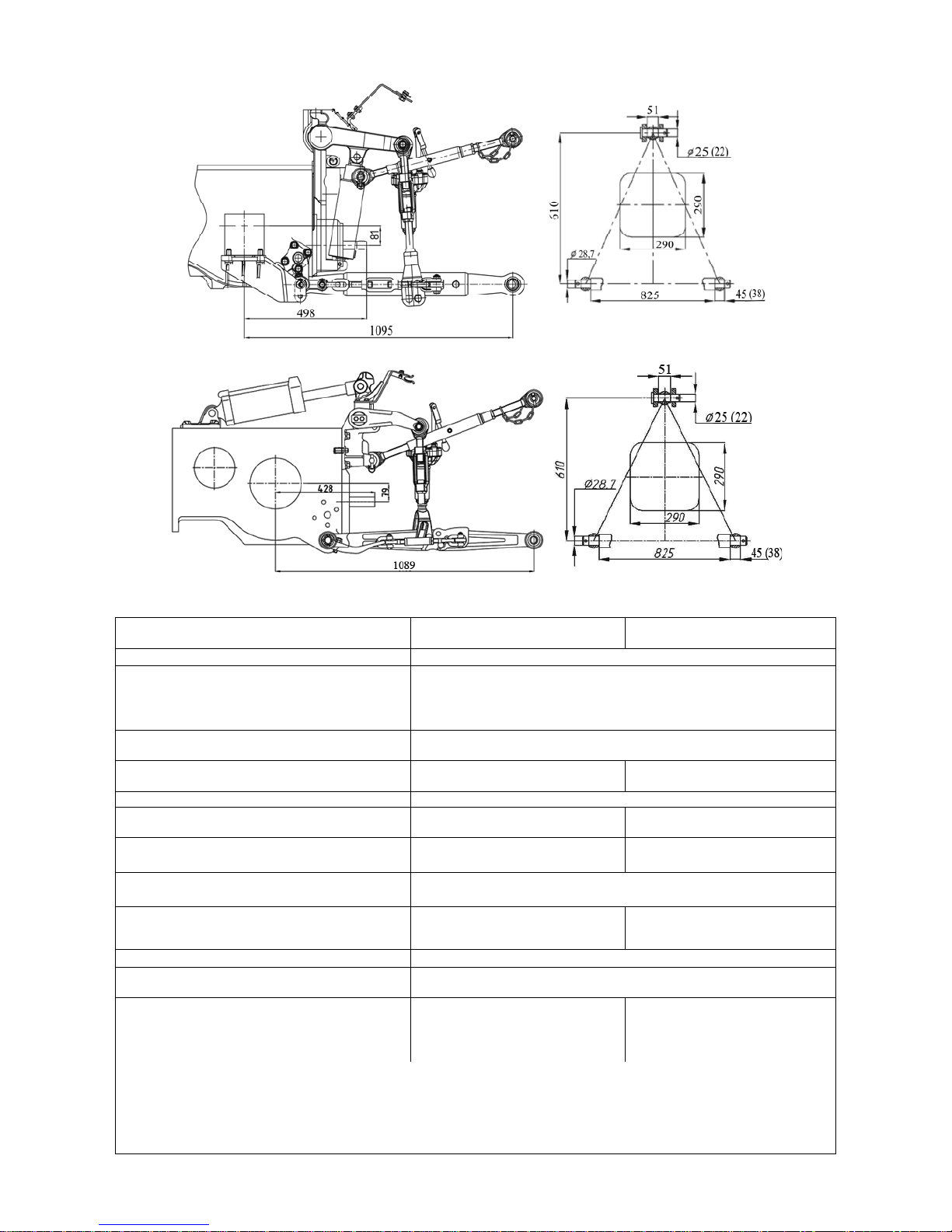
952.5-0000010 OM
100
Figure 4.3.1 – Rear lift linkage diagramm of “LL-2” type (with hydraulic lift)
Figure 4.3.2 – Rear lift linkage diagramm of “LL-2” type (with draft control unit)
Table 4.1 – Basic parameters and coupling dimensions of RLL
LL-2 with hydraulic lift LL-2 with draft control unit
Standard size (configuration)
of the device
(figure 4.3.1) (figure 4.3.2)
1 Category (acc. to ISO 730-1)
Category 2
2 Design features
Device consisting of three links (upper one and two lower
ones), pivot-connected with the tractor;
free ends of links with hinge pivots are coupled during implement coupling with the implement’s elements coupled
3 Purpose
To connect (mount) or coupling of mounted, semi-mounted
implements
4 Lower links
Solid
(optional - telescopic)
Split with hinge pivots
(optional - telescopic)
5 Length of lower links, mm 885
6 Hinged joint width of the upper (lower)
link, mm
51 (45) acc.to ISO 730-1
51 (38) acc.to GOST10677
51 (45) acc.to ISO 730-1
51 (38) acc.to GOST 10677
7 Diameter of a pin of a rear-end hinged
joint of the upper link, mm
25 acc.to ISO 730-1
22 acc.to GOST 10677
25 acc.to ISO 730-1
22 acc.to GOST 10677
8 Diameter of holes in rear hinge joints of
lower links, mm
28,7
9 Distance between PTO shaft end extension face and suspension axis, mm
597 661
10 Column height 1), mm
610
11 Length of the suspension axis along the
shoulders 1), mm
825
12 Lifting power of the device, kN:
а) on the suspension axis;
b) at overhang of 610 mm from the sus-
pension axis
42
27
30
18
______________________________________________________________________________________
____________________________________
1)
Dimension refers to the implement coupled.
2)
It is not allowed to give RLL load exceeding loading of tires specified by loading instructions set forth
in subsection” Selection of optimal inner pressure in tires depending on operational conditions and load on tractor axles”
 Loading...