

MTU 8 V 2000 M50A, M50B, 8 V 2000 M51A, M51B, 16 V 2000 M51A Operating Instructions Manual
...Page 1

Operating Instructions
Diesel Engine
8 V 2000 M50A, M50B
8 V 2000 M51A, M51B
12 V 2000 M50A, M50B
12 V 2000 M51A, M51B
16 V 2000 M50A, M50B
16 V 2000 M51A, M51B
MW15550/07E
Page 2

Printed in Germany
© 2013 Copyright MTU Friedrichshafen GmbH
This Publication is protected by copyright and may not be used in any way whether in whole or in part without the prior
written permission of MTU Friedrichshafen GmbH. This restriction also applies to copyright, distribution, translation, microfilming and storage or processing on electronic systems including data bases and online services.
This handbook is provided for use by maintenance and operating personnel in order to avoid malfunctions or damage
during operation.
Subject to alterations and amendments.
Page 3

Table of Contents
1 Safety
1.1 Important provisions for all products 6
1.2 Personnel and organizational requirements 7
1.3 Transportation 8
1.4 Safety regulations for maintenance and
repair work 11
1.5 Fire prevention and environmental
protection, fluids and lubricants, auxiliary
materials 14
1.6 Standards for warning notices in the text 16
2 General Information
2.1 Engine side and cylinder designations 17
2.2 Product description 18
2.3 2000 M40-M91A/B engines – Overview 27
2.4 Sensors, actuators and injectors – Overview 28
2.5 Sensors, actuators and injectors – Overview 32
3 Technical Data
3.1 8V 2000 M50A engine data: Enginemounted heat exchanger, reference
condition: Intake-air temperature 25 °C 42
3.2 8V 2000 M50A engine data: Remote heat
exchanger, reference condition: Intake-air
temperature 25 °C 45
3.3 8V 2000 M50B engine data: Enginemounted heat exchanger, reference
condition: Intake-air temperature 25 °C 48
3.4 8V 2000 M50B engine data: Remote heat
exchanger, reference condition: Intake-air
temperature 25 °C 51
3.5 Engine data 8V 2000M51A, engine-mounted
heat exchanger 54
3.6 8V 2000 M51A engine data: Remote heat
exchanger 57
3.7 Engine data 8V 2000M51B, engine-mounted
heat exchanger 60
3.8 8V 2000 M51B engine data: Remote heat
exchanger 63
3.9 12V 2000 M50A engine data: Enginemounted heat exchanger, reference
condition: Intake-air temperature 25 °C 66
3.10 12V 2000 M50A engine data: Remote heat
exchanger, reference condition: Intake-air
temperature 25 °C 69
3.11 12V 2000 M50A engine data: Enginemounted heat exchanger, reference
condition: Intake-air temperature 45 °C 72
3.12 12V 2000 M50A engine data: Remote heat
exchanger, reference condition: Intake air
temperature 45 °C 75
3.13 12V 2000 M50B engine data: Enginemounted heat exchanger, reference
condition: Intake-air temperature 25 °C 78
3.14 12V 2000 M50B engine data: Remote heat
exchanger, reference condition: Intake-air
temperature 25 °C 81
3.15 12V 2000 M50B engine data: Enginemounted heat exchanger, reference
condition: Intake-air temperature 45 °C 84
3.16 12V 2000 M50B engine data: Remote heat
exchanger, reference condition: Intake-air
temperature 45 °C 87
3.17 Engine data 12V 2000 M51A, enginemounted heat exchanger 90
3.18 12V 2000 M51A engine data: Remote heat
exchanger 93
3.19 Engine data 12V 2000M51B, enginemounted heat exchanger 96
3.20 12V 2000 M51B engine data: Remote heat
exchanger 99
3.21 16V 2000 M50A engine data: Enginemounted heat exchanger, reference
condition: Intake-air temperature 25 °C 102
3.22 16V 2000 M50A engine data: Remote heat
exchanger, reference condition: Intake-air
temperature 25 °C 105
3.23 16V 2000 M50A engine data: Enginemounted heat exchanger, reference
condition: Intake-air temperature 45 °C 108
3.24 16V 2000 M50A engine data: Remote heat
exchanger, reference condition: Intake-air
temperature 45 °C 111
3.25 16V 2000 M50B engine data: Enginemounted heat exchanger, reference
condition: Intake-air temperature 25 °C 114
3.26 16V 2000 M50B engine data: Remote heat
exchanger, reference condition: Intake-air
temperature 25 °C 117
3.27 16V 2000 M50B engine data: Enginemounted heat exchanger, reference
condition: Intake-air temperature 45 °C 120
3.28 16V 2000 M50B engine data: Remote heat
exchanger, reference condition: Intake-air
temperature 45 °C 123
3.29 Engine data 16V 2000M51A, enginemounted heat exchanger 126
MW15550/07E 2013-01 | Table of Contents | 3
DCL-ID: 0000013394 - 004
Page 4

3.30 16V 2000 M51A engine data: Remote heat
exchanger 129
3.31 Engine data 16V 2000M51B, enginemounted heat exchanger 132
3.32 16V 2000 M51B engine data: Remote heat
exchanger 135
3.33 Firing order 138
3.34 Engine – Main dimensions 139
4 Operation
4.1 LOP – Controls 140
4.2 Putting the engine into operation (out-ofservice period > 3 months) 142
4.3 Putting the engine into operation after
scheduled out-of-service period 143
4.4 Starting the engine from LOP 144
4.5 Operational checks 145
4.6 Stopping the engine at the LOP 146
4.7 Emergency stop from LOP 147
4.8 After stopping the engine 148
4.9 Plant cleaning 149
5 Maintenance
5.1 Maintenance task reference table [QL1] 150
5.2 Maintenance task reference table [QL1] 151
6 Troubleshooting
6.1 ECU alarms 152
6.2 Troubleshooting 162
6.3 LOP fault messages 165
7 Task Description
7.1 SOLAS 170
7.1.1 SOLAS shielding as per MTN 5233 –
Installation 170
7.1.2 SOLAS shielding – Installation as per MTN
5233 171
7.1.3 SOLAS shielding – Installation 172
7.1.4 Installation locations for SOLAS shielding 173
7.2 Engine 178
7.2.1 Engine – Barring manually 178
7.2.2 Engine cranking on starter 179
7.3 Cylinder Liner 180
7.3.1 Cylinder liner – Endoscopic examination 180
7.3.2 Instructions and comments on endoscopic and
visual examination of cylinder liners 182
7.4 Crankcase Breather 184
7.4.1 Crankcase breather – Oil separator element
replacement, diaphragm check and
replacement 184
7.4.2 Crankcase breather – Cleaning oil separator
element 186
7.4.3 Crankcase ventilation – Oil separator element
replacement, diaphragm check and
replacement 187
7.5 Valve Drive 189
7.5.1 Valve clearance – Check and adjustment 189
7.5.2 Cylinder head cover – Removal and
installation 192
7.6 Injection Pump / HP Pump 193
7.6.1 Injection pump – Replacement 193
7.6.2 Injection pump – Removal and installation 194
7.7 Injection Valve / Injector 197
7.7.1 Injector – Replacement 197
7.7.2 Injector – Removal and installation 198
7.8 Fuel System 202
7.8.1 HP fuel line – Pressure pipe neck replacement 202
7.8.2 Fuel – Draining 204
7.8.3 Fuel system – Venting 205
7.9 Fuel Filter 207
7.9.1 Fuel filter – Replacement 207
7.9.2 Fuel prefilter – Differential pressure check
and adjustment of gauge 209
7.9.3 Fuel prefilter – Draining 210
7.9.4 Fuel prefilter – Flushing 211
7.9.5 Fuel prefilter – Filter element replacement 213
7.10 Charge-Air Cooling General, Left-Hand Side 215
7.10.1 Intercooler – Checking condensate drain line
for coolant discharge and obstruction 215
7.11 Air Filter 216
7.11.1 Air filter – Replacement 216
7.11.2 Air filter – Removal and installation 217
7.12 Air Intake 218
7.12.1 Service indicator – Signal ring position check
(optional) 218
7.13 Starting Equipment 219
7.13.1 Starter – Condition check 219
7.14 Lube Oil System, Lube Oil Circuit 220
7.14.1 Engine oil – Level check 220
7.14.2 Engine oil – Change 221
7.15 Oil Filtration / Cooling 222
7.15.1 Oil dipstick — Marking 222
7.15.2 Engine oil filter – Replacement 223
7.15.3 Centrifugal oil filter – Cleaning and filtersleeve replacement 225
7.16 Coolant Circuit, General, High-Temperature
Circuit 228
4 | Table of Contents | MW15550/07E 2013-01
DCL-ID: 0000013394 - 004
Page 5

7.16.1 Drain and venting points 228
7.16.2 Engine coolant – Level check 233
7.16.3 Engine coolant – Change 234
7.16.4 Engine coolant – Draining 235
7.16.5 Engine coolant – Filling 236
7.16.6 HT coolant pump – Relief bore check 237
7.16.7 Engine coolant – Sample extraction and
analysis 238
7.17 Raw Water Pump with Connections 239
7.17.1 Raw water pump – Relief bore check 239
7.18 Belt Drive 240
7.18.1 Drive belt – Condition check 240
7.19 Battery-Charging Generator 241
7.19.1 Battery-charging generator drive – Drive belt
check and adjustment 241
7.19.2 Battery-charging generator drive – Drive belt
replacement 243
7.20 Engine Mounting / Support 245
7.20.1 Engine mounting – Checking condition of
resilient mounts 245
7.21 Wiring (General) for Engine/Gearbox/Unit 246
7.21.1 Engine wiring – Check 246
7.22 Accessories for (Electronic) Engine
Governor / Control System 247
7.22.1 Engine governor and connectors – Cleaning 247
7.22.2 Engine monitoring unit and connectors –
Cleaning 248
7.22.3 Start interlock limit switch – Check 249
7.22.4 ECU – Plug connections check 250
7.22.5 Engine monitoring unit – Plug connection
check 251
7.22.6 Engine control unit – Removal and installation 252
7.23 Emergency Instrumentation (Local
Operating Panel) 254
7.23.1 LOP and connectors – Cleaning 254
7.23.2 LOP – Visual inspection 255
7.23.3 LOP – Test procedures 257
8 Appendix A
8.1 Abbreviations 259
8.2 MTU contact persons/service partners 262
9 Appendix B
9.1 Special Tools 263
9.2 Index 270
MW15550/07E 2013-01 | Table of Contents | 5
DCL-ID: 0000013394 - 004
Page 6

1 Safety
1.1 Important provisions for all products
Nameplate
The product is identified by nameplate, model designation or serial number and must match with the
information on the title page of this manual.
Nameplate, model designation or serial number can be found on the product.
General information
This product may pose a risk of injury or damage in the following cases:
• Incorrect use
• Operation, maintenance and repair by unqualified personnel
• Modifications or conversions
• Noncompliance with the safety instructions and warning notices
Correct use
The product is intended exclusively for the application specified in the contract or defined at the time of
delivery.
This means that the equipment must be operated:
• Within the permissible operating parameters in accordance with the (→ product data)
• With fluids and lubricants approved by the manufacturer in accordance with the (→ Fluids and Lubricants Specifications of the manufacturer)
• With spare parts approved by the manufacturer in accordance with the (→ applicable Spare Parts
Catalog)
• In the original as-delivered configuration or in a configuration approved by the manufacturer in writing (including engine control/parameters)
• In compliance with all safety instructions and in adherence to all warning notices in this manual
• In accordance with the maintenance requirements over the entire service life of the product (→ Maintenance Schedule)
• In compliance with the maintenance and repair instructions contained in this manual, in particular
with regard to the specified tightening torques
• With the exclusive use of technical personnel trained in commissioning, operation, maintenance and
repair
• By contracting only workshops authorized by the manufacturer to carry out repair and overhaul
Any other use is considered improper use and increases the risk of personnel injury or material damage
in product operation.The manufacturer will accept no liability for such damage.
Modifications or conversions
Unauthorized modifications to the product compromise safety.
The manufacturer will accept no liability or warranty claims for any damage caused by unauthorized
modifications or conversions.
Spare parts
Only genuine spare parts must be used to replace components or assemblies.
The manufacturer will accept no liability or warranty claims for any damage caused by the use of other
spare parts.
6 | Safety |
MW15550/07E 2013-01
TIM-ID: 0000040530 - 001
Page 7

1.2 Personnel and organizational requirements
Organizational measures of the operator
This manual must be issued to all personnel involved in operation, maintenance, repair or transportation.
Keep this manual handy in the vicinity of the product such that it is accessible to operating, maintenance, repair and transport personnel at all times.
Use this manual as a basis for instructing personnel on product operation and repair, whereby the safety-relevant instructions, in particular, must be read and understood.
This is particularly important in the case of personnel who only occasionally perform work on or around
the product. This personnel must be instructed repeatedly.
Personnel requirements
All work on the product shall be carried out by trained and qualified personnel only.
• Training at the Training Center of the manufacturer
• Qualified personnel specialized in mechanical and plant engineering
The operator must define the responsibilities of the personnel involved in operation, maintenance, repair and transport.
Working clothes and protective equipment
Wear proper protective clothing for all work.
MW15550/07E 2013-01 | Safety | 7
TIM-ID: 0000040531 - 001
Page 8
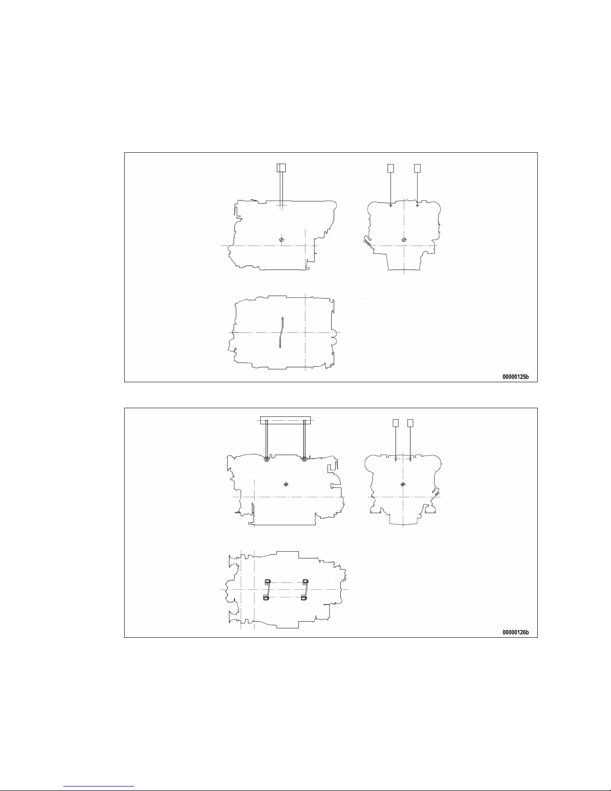
1.3 Transportation
Transport without flange-mounted gearbox
Illustration is essentially valid for 8V 2000 M engines
Illustration is essentially valid for 12/16V 2000 M engines
Transport with flange-mounted gearbox
Illustration is essentially valid for 8V 2000 M engines
8 | Safety |
MW15550/07E 2013-01
TIM-ID: 0000002620 - 003
Page 9
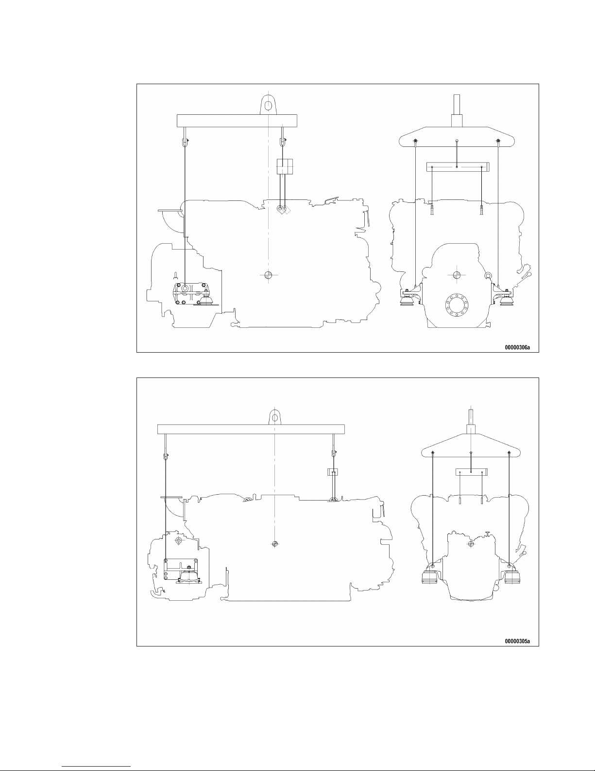
Illustration is essentially valid for 12/16V 2000 M engines
Only use the lifting eyes provided to lift the engine.
The eyebolts mounted at the driving end and on the gearbox must not be used for transporting plants
with flange-mounted gearboxes.
Only use transport and lifting devices approved by MTU.
Take the engine's center of gravity into account.
MW15550/07E 2013-01
| Safety | 9
TIM-ID: 0000002620 - 003
Page 10

The engine must only be transported in installation position, max. permissible diagonal pull 10°.
If the engine is supplied with special aluminum foil packing, lift the engine at the lifting eyes of the bearing pedestal or use a means of transportation which is appropriate for the given weight (forklift truck).
Install the crankshaft locking device and the locking screws for the engine mounts prior to engine transportation.
Secure the engine against tilting during transport. In particular when going down inclines or ramps, the
engine must be secured against moving and tilting.
Setting the engine down after transport
Only set down engine on a firm, level surface.
Make sure that the consistency and load-bearing capacity of the ground or support surface is adequate.
Never set an engine down on the oil pan unless expressively authorized to do so by MTU on a case-tocase basis.
10 | Safety | MW15550/07E 2013-01
TIM-ID: 0000002620 - 003
Page 11

1.4 Safety regulations for maintenance and repair work
Safety regulations prior to maintenance and repair work
Have maintenance or repair work carried out by qualified and authorized personnel only.
Allow the product to cool down to less than 50°C before starting maintenance work (risk of explosion
of oil vapors, fluids and lubricants, risk of burning).
Before starting work, relieve pressure in systems and compressed-air lines which are to be opened. Use
suitable containers of adequate capacity to catch fluids and lubricants.
When changing the oil or working on the fuel system, ensure that the engine room is adequately ventilated.
Never carry out maintenance and repair work with the product in operation.
Carry out function checks on a product in operation only if expressly permitted to do so.
Secure the product against unintentional starting, e.g. with start interlock.
Attach "Do not operate" sign in the operating area or to control equipment.
Disconnect the battery. Lock circuit breakers.
Close the main valve on the compressed-air system and vent the compressed-air line when pneumatic
starters are fitted.
Disconnect the control equipment from the product.
The following additional instructions apply to starters with beryllium copper pinion:
• Breathing protection of filter class P2 must be applied during maintenance work to avoid health hazards caused by the beryllium-containing pinion. Do not blow out the interior of the flywheel housing
or the starter with compressed air. Clean the flywheel housing inside with a class H dust extraction
device as an additional measure.
Safety regulations during maintenance and repair work
Take special care when removing ventilation or plug screws from the product. Cover the screw or plug
with a rag to prevent fluids escaping under pressure.
Take care when draining hot fluids and lubricants (risk of burning).
Use only proper and calibrated tools. Observe the specified tightening torques during assembly or disassembly.
Carry out work only on assemblies or plants which are properly secured.
Never use lines for climbing.
Keep fuel injection lines and connections clean.
Always seal connections with caps or covers if a line is removed or opened.
Take care not to damage lines, in particular fuel lines, during maintenance and repair work.
Ensure that all retainers and dampers are installed correctly.
Ensure that all fuel injection and pressurized oil lines are installed with enough clearance to prevent
contact with other components. Do not place fuel or oil lines near hot components.
Do not touch elastomeric seals if they have carbonized or resinous appearance unless hands are properly protected.
Note cooling time for components which are heated for installation or removal (risk of burning).
When working high on the equipment, always use suitable ladders and work platforms. Make sure components or assemblies are placed on stable surfaces.
MW15550/07E 2013-01
| Safety | 11
TIM-ID: 0000040535 - 001
Page 12

Ensure particular cleanness during maintenance and repair work on the product. After completion of
maintenance and repair work, make sure that no loose objects are in/on the product (e.g. cloths and
cable ties)
Safety regulations after completion of maintenance and repair work
Before barring, make sure that nobody is standing in the danger zone of the product.
Check that all guards have been reinstalled and that all tools and loose parts have been removed after
working on the product (in particular, the barring tool).
Welding work
Welding operations on the product or mounted units are not permitted. Cover the product when welding
in its vicinity.
Before starting welding work:
• Switch off the power supply master switch.
• Disconnect the battery.
• Separate the electrical ground of electronic equipment from the ground of the unit.
No other maintenance or repair work must be carried out in the vicinity of the product while welding is
going on. Risk of explosion or fire due to oil vapors and highly flammable fluids and lubricants.
Do not use product as ground terminal.
Never position the welding power supply cable adjacent to, or crossing wiring harnesses of the product.
The welding current may otherwise induce an interference voltage in the wiring harnesses which could
conceivably damage the electrical system.
Remove parts (e.g. exhaust pipes) which are to be welded from the product beforehand.
Hydraulic installation and removal
Check the function and safe operating condition of tools and fixtures to be used. Use only the specified
devices for hydraulic removal/installation procedures.
Observe the max. permissible push-on pressure specified for the equipment.
Do not attempt to bend or apply force to lines.
Before starting work, pay attention to the following:
• Vent the hydraulic installation/removal tool, the pumps and the lines at the relevant points for the
equipment to be used (e.g. open vent plugs, pump until bubble-free air emerges, close vent plugs).
• For hydraulic installation, screw on the tool with the piston retracted.
• For hydraulic removal, screw on the tool with the piston extended.
For a hydraulic installation/removal tool with central expansion pressure supply, screw spindle into
shaft end until correct sealing is established.
During hydraulic installation and removal, ensure that nobody is standing in the immediate vicinity of
the component to be installed/removed.
Working with batteries
Observe the safety instructions of the battery manufacturer when working with batteries.
Gases emanating from the battery are explosive. Avoid sparks and naked flames.
Do not allow electrolyte to come in contact with skin or clothing.
Wear protective clothing and protective gloves.
Never place tools on the battery.
Before connecting the cable to the battery, check the battery polarity.Battery pole reversal may lead to
injury through the sudden discharge of acid or bursting of the battery body.
12 | Safety |
MW15550/07E 2013-01
TIM-ID: 0000040535 - 001
Page 13

Working on electrical and electronic assemblies
Always obtain the permission of the person in charge before commencing maintenance and repair work
or switching off any part of the electronic system required to do so.
De-energize the appropriate areas prior to working on assemblies.
Do not damage cabling during removal work. When reinstalling ensure that wiring is not damaged during operation by contact with sharp objects, by rubbing against other components or by a hot surface.
Do not secure cables on lines carrying fluids.
Do not use cable binders to secure cables.
Always use connector pliers to tighten union nuts on connectors.
Subject the device as well as the product to a function check on completion of all repair work. In particular, check the function of the engine emergency stop feature.
Store spare parts properly prior to replacement, i.e. protect them against moisture in particular. Pack
defective electronic components and assemblies in a suitable manner when dispatched for repair, i.e.
protected, in particular, against moisture and impact and wrapped in antistatic foil if necessary.
Working with laser equipment
When working with laser equipment, always wear special laser-protection goggles (hazard due to heavily focused radiation).
Laser equipment must be fitted with the protective devices necessary for safe operation according to
type and application.
For conducting light-beam procedures and measurement work, only the following laser devices must be
used:
• Laser devices of classes 1, 2 or 3A.
• Laser devices of class 3B, which have maximum output in the visible wavelength range (400 to 700
nm), a maximum output of 5 mW, and in which the beam axis and surface are designed to prevent
any risk to the eyes.
MW15550/07E 2013-01 | Safety | 13
TIM-ID: 0000040535 - 001
Page 14

1.5 Fire prevention and environmental protection, fluids and
lubricants, auxiliary materials
Fire prevention
Rectify any fuel or oil leaks immediately. Oil or fuel on hot components can cause fires – therefore always keep the product in a clean condition. Do not leave cloths soaking with fluids and lubricants on
the product. Do not store combustible materials near the product.
Do not carry out welding work on pipes and components carrying oil or fuel. Before welding, clean with
a nonflammable fluid.
When starting the engine with an external power source, connect the ground lead last and remove it
first. To avoid sparks in the vicinity of the battery, connect the ground lead from the external power
source to the ground lead of the engine or to the ground terminal of the starter.
Always keep suitable firefighting equipment (fire extinguishers) at hand and familiarize yourself with
their use.
Noise
Noise can lead to an increased risk of accident if acoustic signals, warning shouts or noises indicating
danger are drowned.
Wear ear protectors in work areas with a sound pressure level in excess of 85dB (A).
Environmental protection and disposal
Modification or removal of any mechanical/electronic components or the installation of additional components as well as the execution of calibration processes that might affect the emission characteristics
of the product are prohibited by emission regulations. Emission control units/systems may only be
maintained, exchanged or repaired if the components used for this purpose are approved by the manufacturer. Noncompliance with these guidelines will lead to forfeiture of the operating permit issued by
the emission monitoring authorities. The manufacturer does not accept any liability for violations of the
emission regulations. The maintenance schedules of the manufacturer must be observed over the entire
life cycle of the product.
Dispose of used fluids, lubricants and filters in accordance with local regulations.
Within the EU, batteries can be returned free of charge to the manufacturer where they are subjected to
proper recycling procedures.
Auxiliary materials, fluids and lubricants
The Fluids and Lubricants Specifications will be amended or supplemented as necessary. Prior to operation, make sure that the latest version is used. The applicable version may be downloaded at: http://
www.mtu-online.com/mtu/mtu-valuecare/mtu-valueservice-Technische-Dokumentation.
Auxiliary materials, fluids and lubricants might be hazardous goods or toxic substances.When using fluids, lubricants, auxiliary materials and other chemical substances, follow the safety instructions that apply to the product. Take special care when using hot, chilled or caustic materials. When using flammable materials, avoid contact with ignition sources and do not smoke.
Used oil
Used oil contains harmful combustion residue.
Rub barrier cream into hands.
Wash hands after contact with used oil.
14 | Safety |
MW15550/07E 2013-01
TIM-ID: 0000040536 - 002
Page 15

Lead
• Adopt suitable measures to avoid the formation of lead dust.
• Switch on extraction system.
• When working with lead or lead-containing compounds, avoid direct contact to the skin and do not
inhale lead vapors.
• Wash hands after contact with lead or lead-containing substances.
Compressed air
Observe special safety precautions when working with compressed air:
• Unauthorized use of compressed air, e.g. forcing flammable liquids (danger class AI, AII and B) out of
containers, results in a risk of explosion.
• Wear goggles when blowing off components or blowing away chips.
• Forcing compressed air into thin-walled containers (e.g. containers made of tin, plastic and glass) for
drying purposes or to check for leaks, results in a risk of bursting.
• Pay special attention to the pressure level in the compressed air network or pressure vessel.
• Assemblies or products to be connected must either be designed for this pressure, or, if the permitted pressure for the connecting elements is lower than the pressure required, a pressure reducing
valve and safety valve (set to permitted pressure) must form an intermediate connection.
• Hose couplings and connections must be securely attached.
• Provide the snout of the air nozzle with a protective disk (e.g. rubber disk).
• First shut off compressed air lines before compressed air equipment is disconnected from the supply
line, or before the equipment or tool is to be replaced.
• Carry out leak test in accordance with the specifications.
Paints and lacquers
• Observe the relevant safety data sheet for all materials.
• When carrying out painting work outside the spray stands provided with fume extraction systems,
ensure that the area is well ventilated. Make sure that neighboring work areas are not impaired.
• Avoid open flames in the vicinity.
• No smoking.
• Observe fire prevention regulations.
• Always wear a mask providing protection against paint and solvent vapors.
Liquid nitrogen
• Observe the relevant safety data sheet for all materials.
• Store liquid nitrogen only in small quantities and always in specified containers (without fixed covers).
• Avoid body contact (eyes, hands).
• Wear protective clothing, protective gloves, closed shoes and protective goggles.
• Make sure that working area is well ventilated.
• Avoid all knocks and jars to the containers, fixtures or workpieces.
Acids/alkaline solutions/urea solution (AdBlue, DEF)
• Observe the relevant safety data sheet for all materials.
• When working with acids and alkaline solutions, wear face mask, gloves and protective clothing.
• Do not inhale vapors.
• If urea solution was swallowed, rinse mouth and drink plenty of water.
• If the solutions was spilled onto clothing, remove the affected clothing immediately.
• In case of skin contact, rinse parts of the body thoroughly with clean water.
• Rinse eyes immediately with eyedrops or clean tap water. Seek medical attention as soon as possible.
MW15550/07E 2013-01
| Safety | 15
TIM-ID: 0000040536 - 002
Page 16
1.6 Standards for warning notices in the text
DANGER
In the event of immediate danger.
Consequences: Death, serious or irreversible injury
• Remedial action
WARNING
In the event of a situation involving potential danger.
Consequences: Death, serious or permanent injury
• Remedial action
CAUTION
In the event of possible danger.
Consequences: Minor or moderate injuries
• Remedial action
NOTICE
In the event of a situation involving potentially adverse effects on the product.
Consequences: Material damage.
• Remedial action
• Additional product information
Warning notices
u This manual with all safety instructions and waring notices must be issued to all personnel involved in
operation, maintenance, repair or transportation.
16 | Safety | MW15550/07E 2013-01
TIM-ID: 0000040578 - 001
Page 17
2 General Information
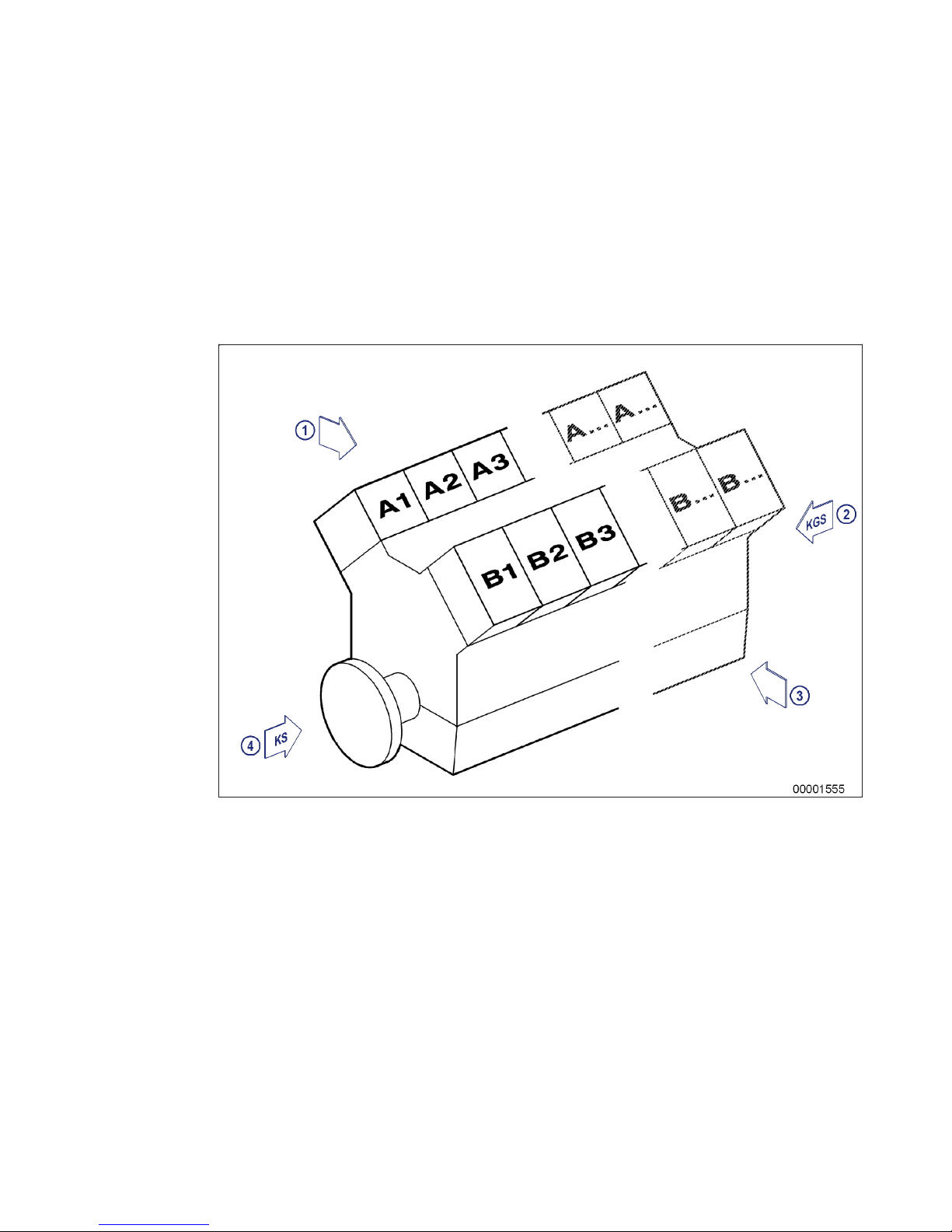
2.1 Engine side and cylinder designations
Engine sides are always designated as viewed from the driving end (KS).
The cylinders of the left engine side are designated "A" and those of the right side "B" (as per DIN ISO
1204). The cylinders of each bank are numbered consecutively, starting with No. 1 at the driving end.
Other components are numbered in the same way, i.e. starting with No. 1 on driving end.
1 Left engine side
2 KGS = Free end
3 Right engine side
4 KS = Driving end
MW15550/07E 2013-01 | General Information | 17
TIM-ID: 0000002185 - 010
Page 18

2.2 Product description
Description of the engine
Engine
The engine is a liquid-cooled four-stroke diesel engine, rotating counterclockwise (seen from driving
end), with direct injection, exhaust turbocharging and intercooling.
The engine is monitored by an engine control and monitoring system.
Monitoring in the engine room is carried out by the engine control and monitoring unit.
Fuel system
Electronically controlled unit injection pumps with jacketed HP lines.
The electronic control unit controls
• Injection start
• Injection quantity
Exhaust system
The exhaust system is equipped with triple-walled, water-cooled exhaust lines.
The triple-walled design permits
• Low surface temperature,
• Reduced amount of heat to be dissipated by the coolant
• Absolute gas-tightness.
Turbocharging
Sequential turbocharging with intercooling (turbochargers can be cut in/out during operation).
Cooling system
Engine cooled by split-circuit cooling system with plate-core heat exchanger.
Service block
The service components are mounted at the auxiliary PTO end.
The arrangement facilitates easy access for maintenance operations.
Service-components:
• Raw water pump, coolant pump
• Fuel duplex filter, switchable
• Lube-oil multiple filter, switchable
• Centrifugal lube oil filter
• Coolant expansion tank
Electronic system
Electronic control and monitoring system with integrated safety and test system, providing interfaces to
Remote Control System (RCS) and Monitoring and Control System (MCS).
18 | General Information |
MW15550/07E 2013-01
TIM-ID: 0000002178 - 005
Page 19

Electronic Engine Control Unit (ECU)
Functions:
• Engine speed control with fuel and speed limitation dependent on engine state and operating conditions;
• Control of sequential turbocharging;
• Data processing logistics for analog and binary signals;
• Interface for data transfer to CAN field bus for remote control and ship-side monitoring;
• RS 232 interface for connection of MTU dialog unit.
Electronic Engine Monitoring Unit (EMU), optional
Functions:
• Data processing logistics for analog and binary signals;
• Interface for data transfer to CAN field bus for remote control and ship-side monitoring.
Electronic Gear Control Unit (GCU), ship-side wall-mounting
Functions:
• Date processing logistics for gear coupling control;
• Input/output signals as well as data transfer to CAN field bus for remote control and ship-side monitoring.
Monitoring in engine room
Engine control and monitoring unit (LOP)
Functions:
• Alphanumeric, monochrome LCD display for monitoring of measured values as well as alarms when
limits are violated;
• Pushbuttons for menu control and dimming unit;
• Combined control and display elements for local engine/gear control;
• Flashing light and horn for summary alarm in engine room;
• Interface to CAN field bus for connected, communicating monitoring system components.
SOLAS – Fire protection specifications
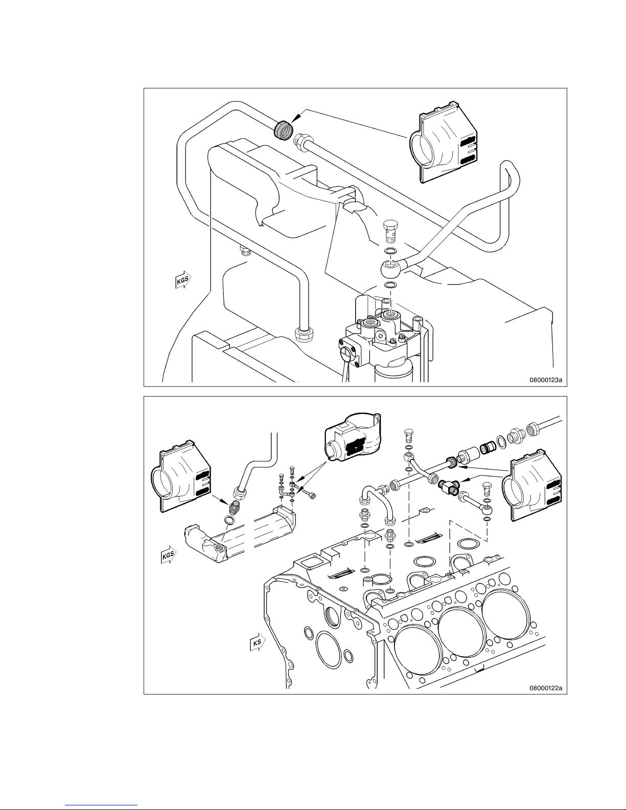
All fuel lines with fuel pressure >1.8 bar are fitted with SOLAS-compliant covers acc. to MTU standard
MTN5233.
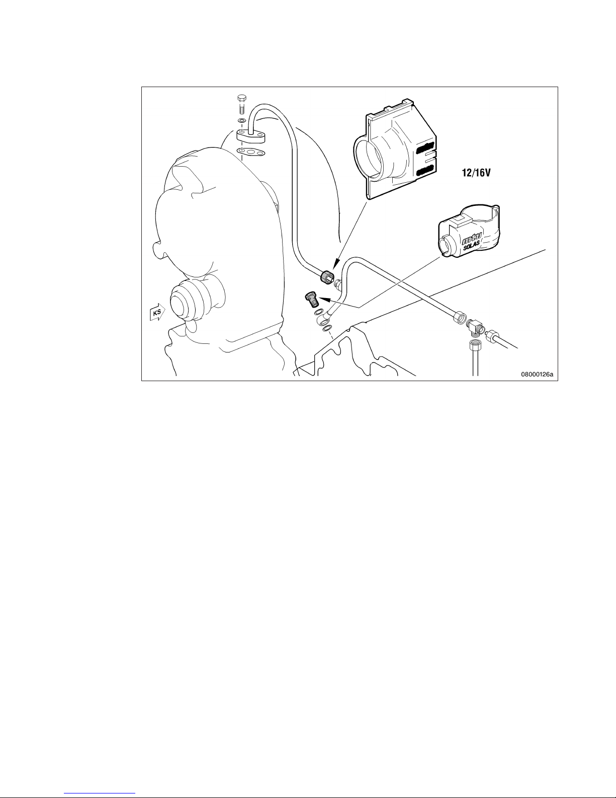
All oil lines with oil pressure >1.8 bar are fitted with SOLAS-compliant covers acc. to MTU standard
MTN5233.
MW15550/07E 2013-01 | General Information | 19
TIM-ID: 0000002178 - 005
Page 20
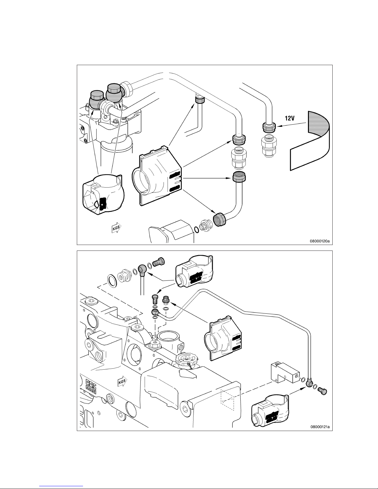
Fuel system covers
20 | General Information | MW15550/07E 2013-01
TIM-ID: 0000002178 - 005
Page 21
MW15550/07E 2013-01 | General Information | 21
TIM-ID: 0000002178 - 005
Page 22
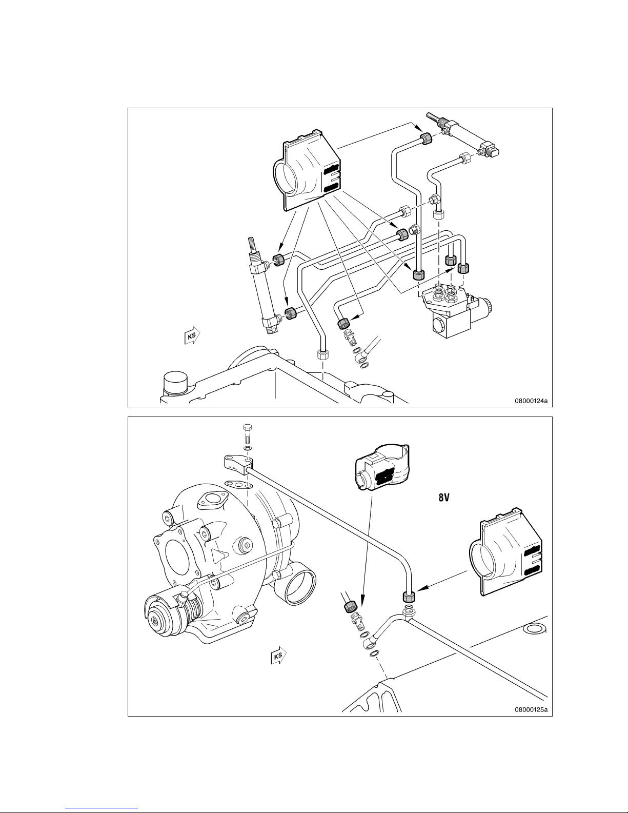
Lube oil system covers
22 | General Information | MW15550/07E 2013-01
TIM-ID: 0000002178 - 005
Page 23
MW15550/07E 2013-01 | General Information | 23
TIM-ID: 0000002178 - 005
Page 24
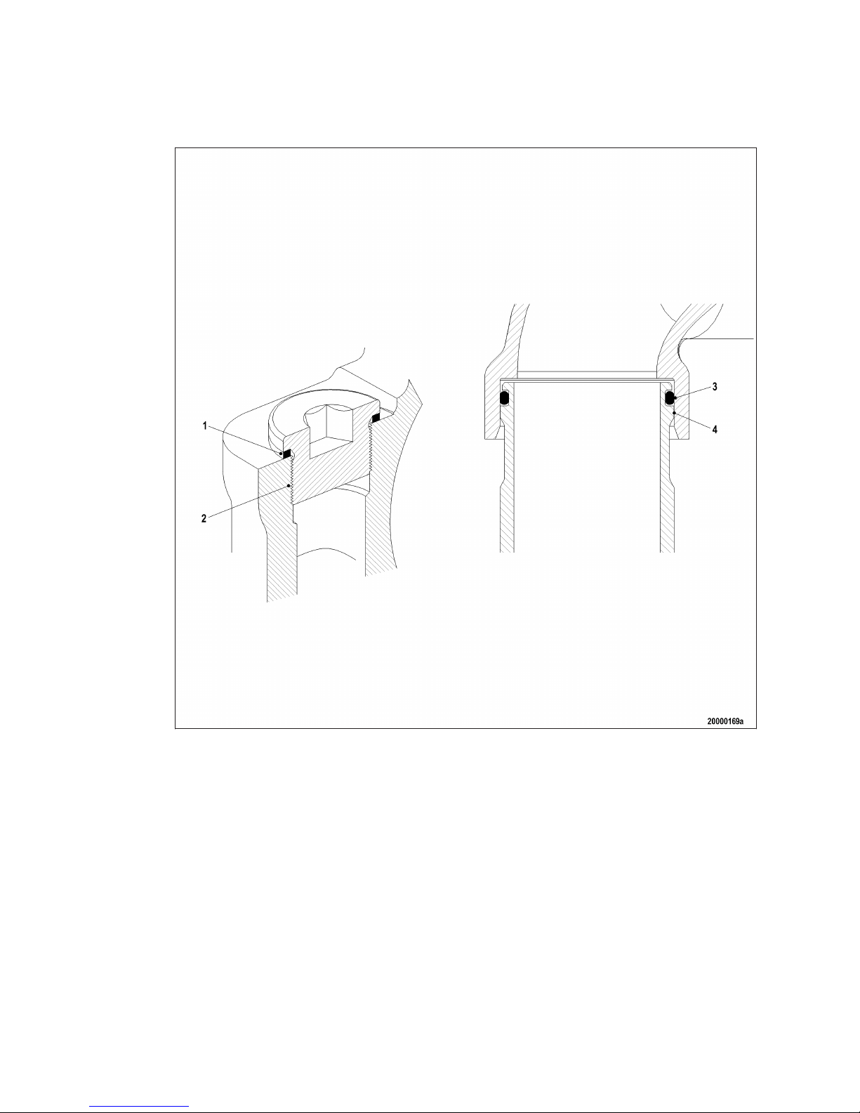
Special unions
The following types of union are spray-proof in case of leakage even without covers and have been confirmed as being SOLAS-compliant by GL and DNV.
Plug-in pipe union
Design precludes lateral spray as the parting line is shielded by the sleeve (4).
Only seepage along the pipeline is possible whereby the pressure is greatly reduced by a faulty O-ring
(3).
The union is confirmed as being SOLAS-compliant by DNV and GL.
Plugs and sensors
Screw-in plugs (2) are sealed toward the outside either with a copper sealing ring (1), according to DIN,
or an O-ring (ISO).
The fluid must first pass the thread in case of a loose threaded union or faulty sealing ring (2).
The pressure is so greatly reduced by this and the faulty sealing ring (2) that any leakage is not under
pressure.
24 | General Information |
MW15550/07E 2013-01
TIM-ID: 0000002178 - 005
Page 25
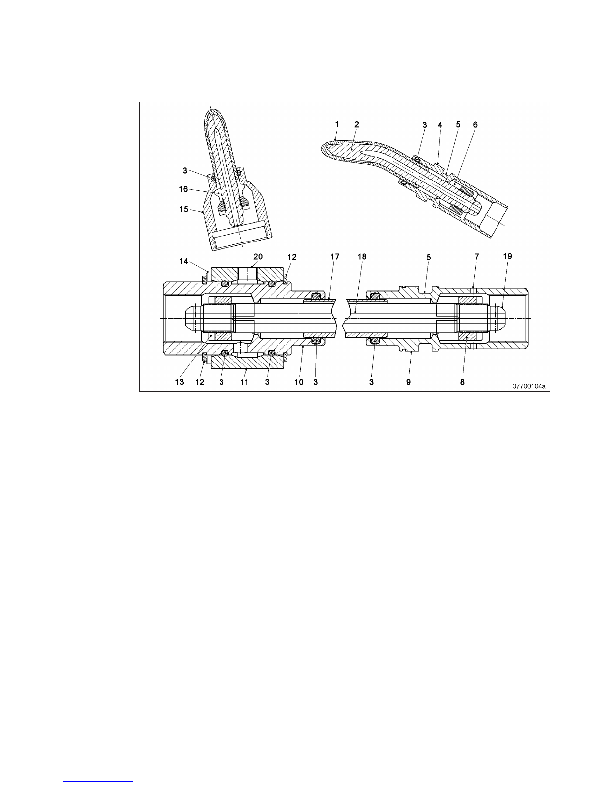
High-pressure unions
1 Jacketed pipe
2 HP line
3 O-ring
4 Union nut
5 Recess for O-ring
6 Thrust ring
7 Leakage overflow bore
8 Thrust ring
9 Union nut
10 Union nut
11 Connecting piece
12 Snap ring
13 Thrust ring
14 Shims
15 Union nut
16 Thrust ring
17 External pipe of HP line
18 Internal pipe of HP line
19 Spherical sealing area
20 Leak fuel connection
The HP fuel line is sealed by the thrust ring (8).
If leakage in the area of the thrust ring (8) or the HP line (5) occurs, the emerging fuel is routed to the
leakage chamber.
Leak fuel is allowed to escape without pressure via the leakage overflow bore (7). The leakage chamber
is sealed toward the outside by the O-rings (3).
This prevents leaking fuel from escaping.
The union is confirmed as being SOLAS-compliant by DNV and GL.
MW15550/07E 2013-01
| General Information | 25
TIM-ID: 0000002178 - 005
Page 26
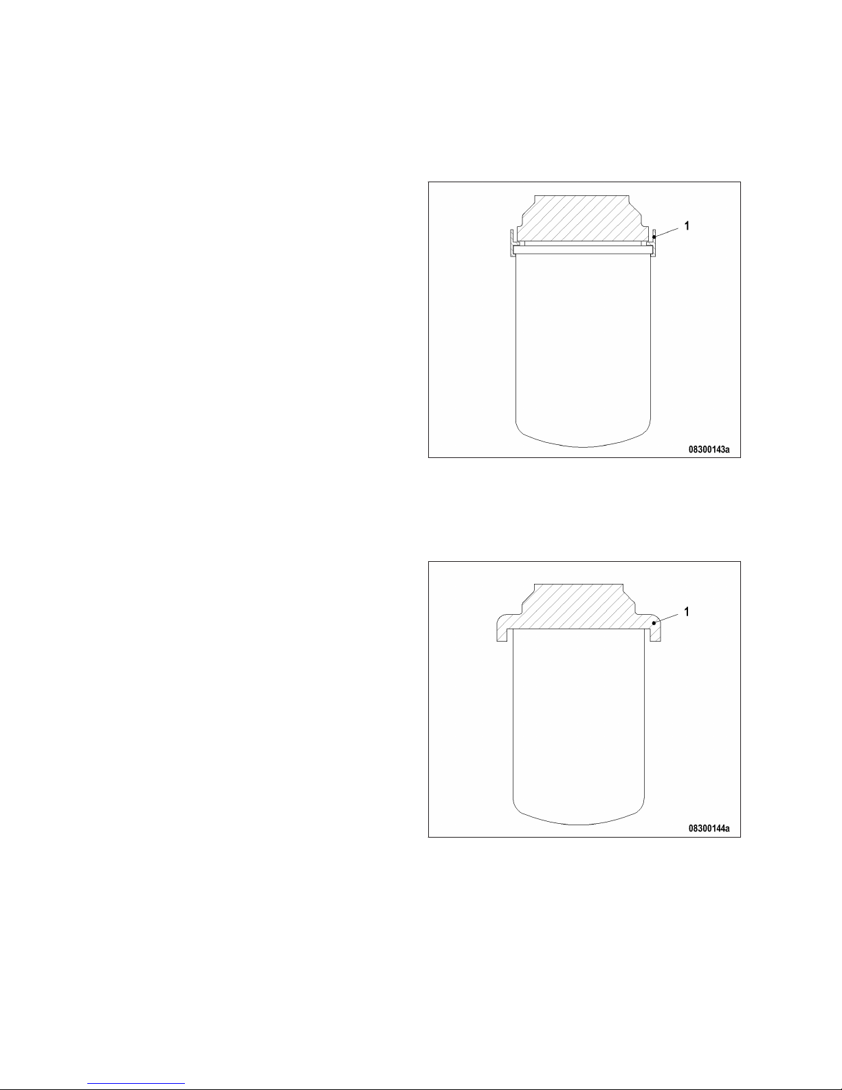
Shielding of fuel filters and lube-oil filters
Shielding with plastic ring
The plastic ring (1) precludes lateral spray.
The fluid is diverted to the catch basin whereby the pressure is greatly reduced.
Shielding by structural overhang
The overhang (1) prevents lateral spray.
The fluid is diverted to the catch basin whereby the pressure is greatly reduced.
26 | General Information |
MW15550/07E 2013-01
TIM-ID: 0000002178 - 005
Page 27
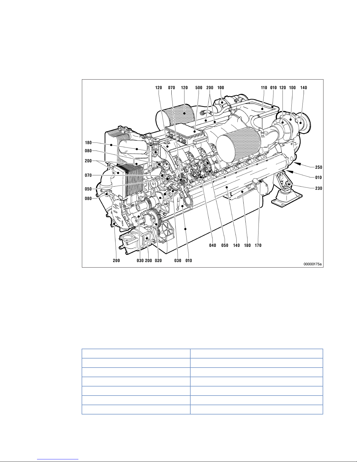
2.3 2000 M40-M91A/B engines – Overview
Engine – Overview of functional groups
010 Crankcase and externally
mounted components
020 Gear train
030 Crank drive
040 Cylinder head
050 Valve gear
070 Injection system (high
pressure)
080 Fuel system (low pressure)
100 Exhaust turbocharger
110 Charge-air cooling
120 Air intake/air supply
140 Exhaust system
170 Starting equipment
180 Lube oil system/lube oil
circuit
200 Coolant circuit
230 Mounting/support
250 PTO systems, driving end
and free end
500 Monitoring, control and
regulation system
Engine model designation
Key to the engine model designations 8/12/16V 2000 M40-M91A/B
8,12,16 Number of cylinders
V Cylinder arrangement: V engine
2000 Series
M Application: M = Marine
4, ...,9 Application segment
0, 1 Design index (0, ..., 9)
A/B Special feature: A = 50 Hz, B = 60 Hz
Table 1: Engine model designation
MW15550/07E 2013-01 | General Information | 27
TIM-ID: 0000002082 - 007
Page 28
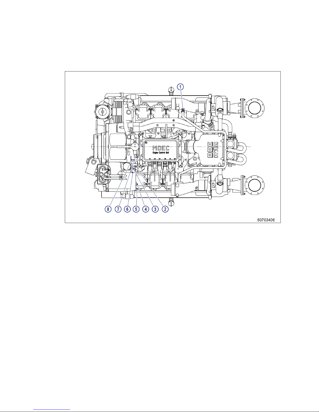
2.4 Sensors, actuators and injectors – Overview
Engine overhead view
1 Intake air temperature
2 Fuel pressure after filter
3 Fuel temperature
4 Lube oil differential pres-
sure
5 Lube oil pressure
6 Coolant level
7 Lube oil temperature
8 Lube oil pressure
28 | General Information | MW15550/07E 2013-01
TIM-ID: 0000038940 - 001
Page 29
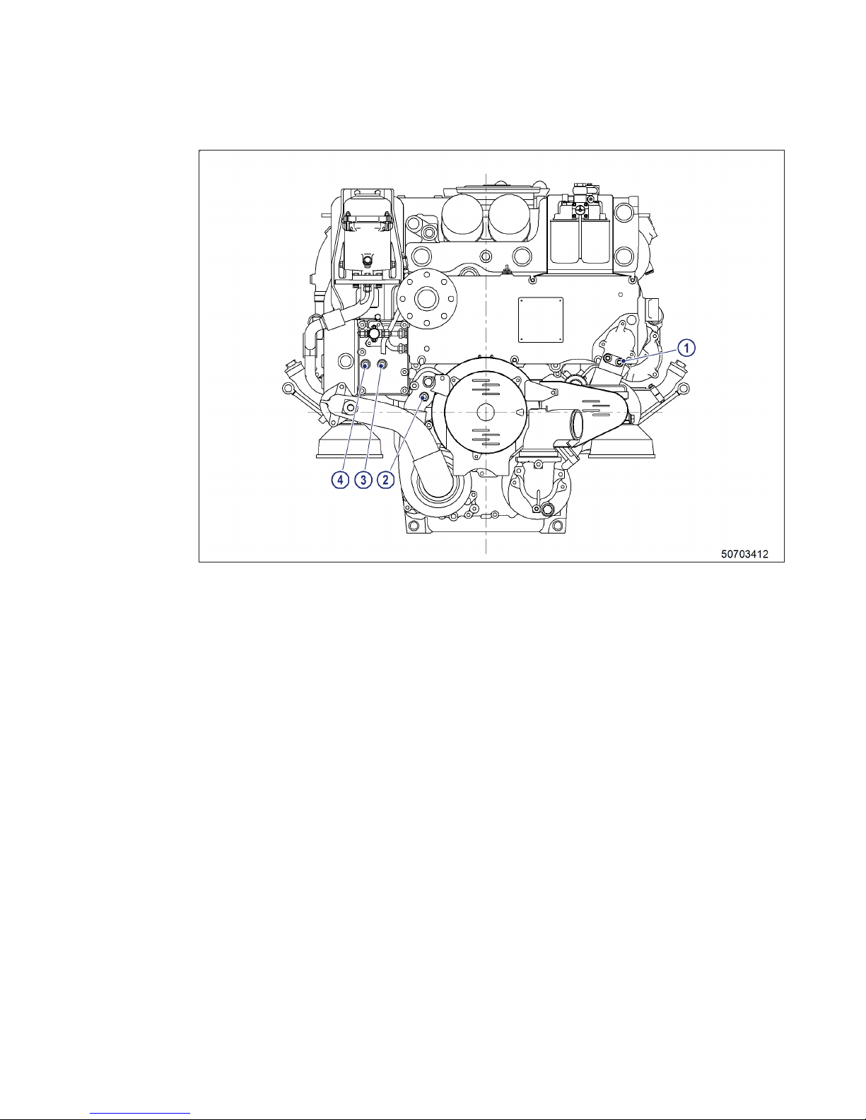
Engine free end
1 Raw water pressure
2 Coolant pressure
3 Coolant temperature
4 Coolant temperature
MW15550/07E 2013-01 | General Information | 29
TIM-ID: 0000038940 - 001
Page 30
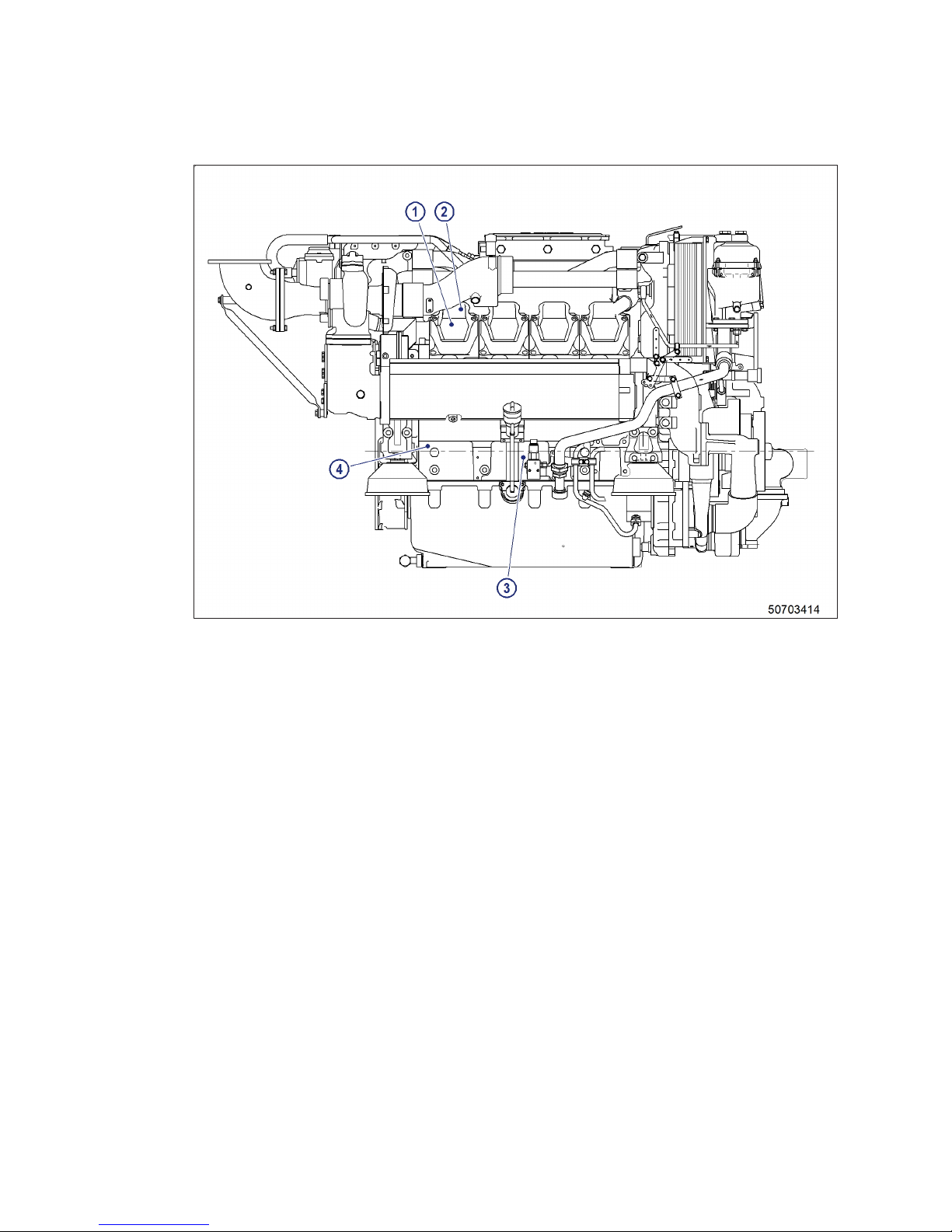
Right engine side
1 Charge-air temperature
2 Charge-air pressure
3 Leak-fuel level
4 Adapter
30 | General Information | MW15550/07E 2013-01
TIM-ID: 0000038940 - 001
Page 31
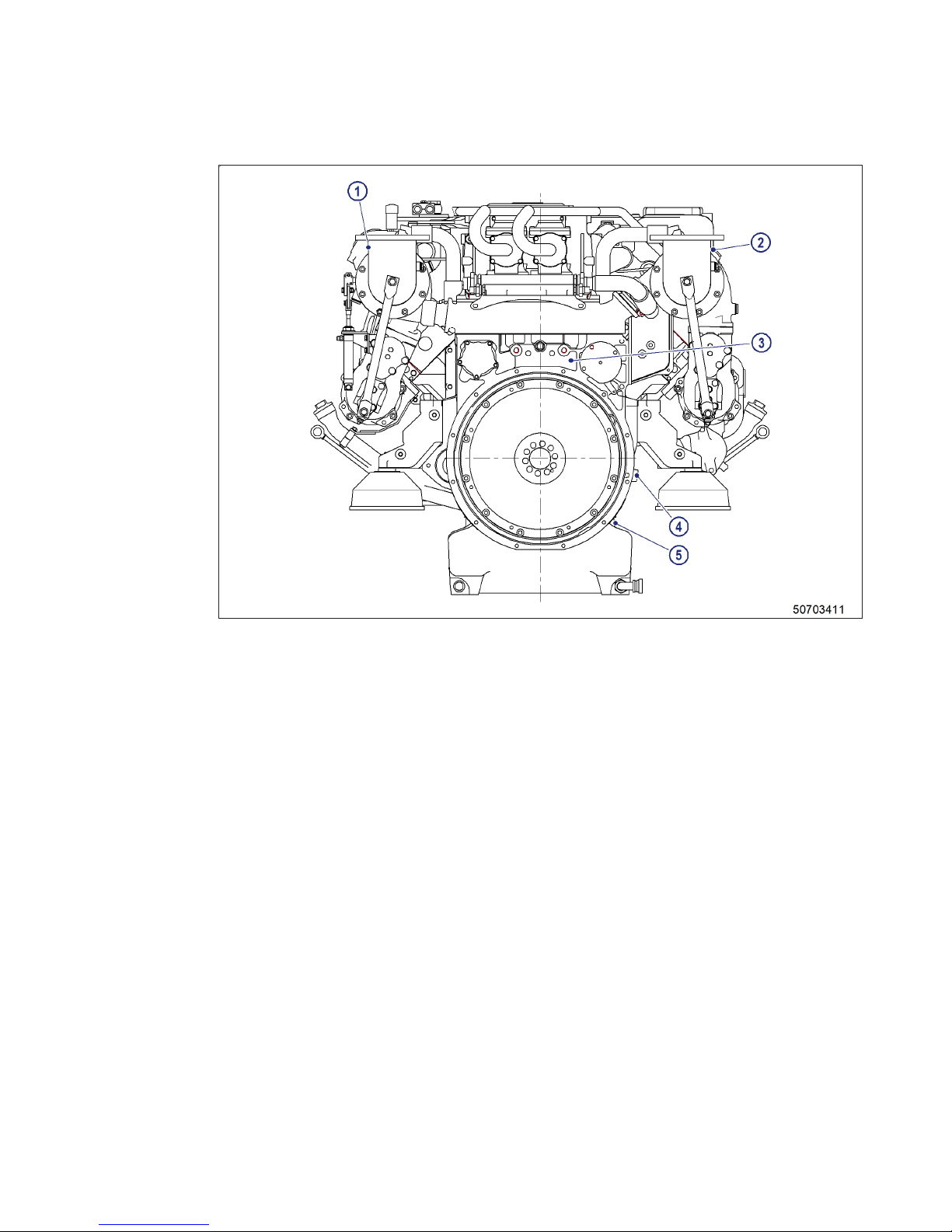
Engine driving end
1 Exhaust temperature, A
side
2 Exhaust temperature, B-
side
3 Camshaft speed
4 Crankshaft speed
5 Crankshaft speed
MW15550/07E 2013-01 | General Information | 31
TIM-ID: 0000038940 - 001
Page 32
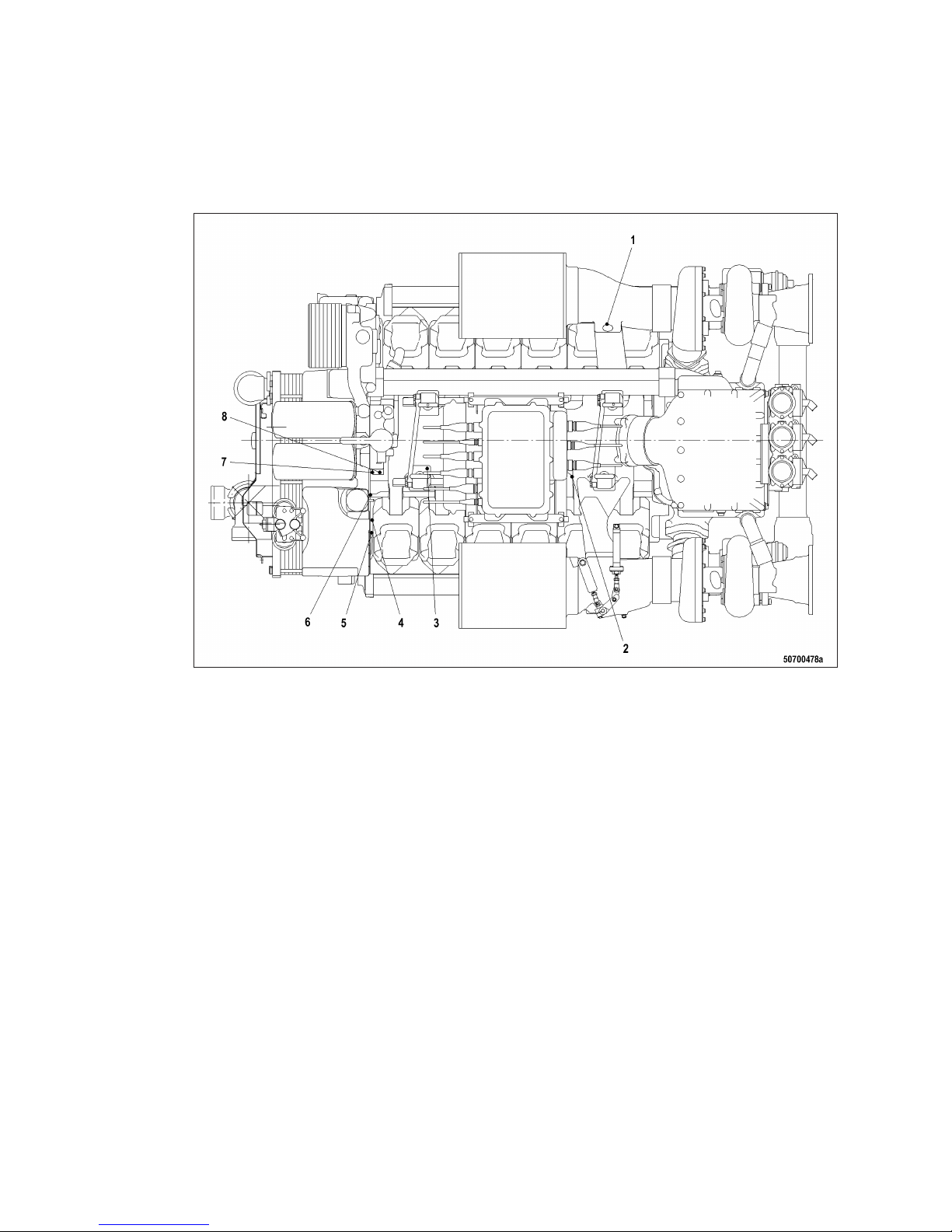
2.5 Sensors, actuators and injectors – Overview
Top view 12V 2000 M
1 B03 (T-Intake air)
2 B10 (P-Charge-air pres-
sure)
3 B09 (T-Charge air)
4 B5.2 (P-Lube oil)
5 F25 (P-Lube-oil difference
over filter)
6 B34 (P-Fuel after filter)
7 B07 (T-Lube oil)
8 B05 (P-Lube oil)
32 | General Information | MW15550/07E 2013-01
TIM-ID: 0000012937 - 003
Page 33
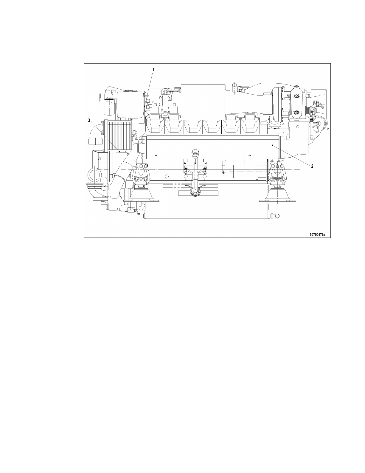
Left engine side 12V 2000 M
1 F33 (H-Engine coolant) 2 Y27 (Turbocharger control
valve)
3 B21 (Raw water pressure)
MW15550/07E 2013-01 | General Information | 33
TIM-ID: 0000012937 - 003
Page 34
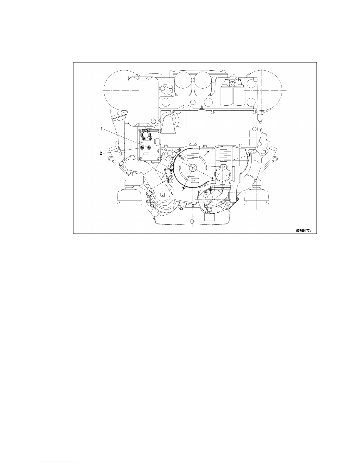
Engine free end 12V 2000 M
1 B06 (T-Coolant) 2 B6.2 (T-Coolant)
34 | General Information | MW15550/07E 2013-01
TIM-ID: 0000012937 - 003
Page 35
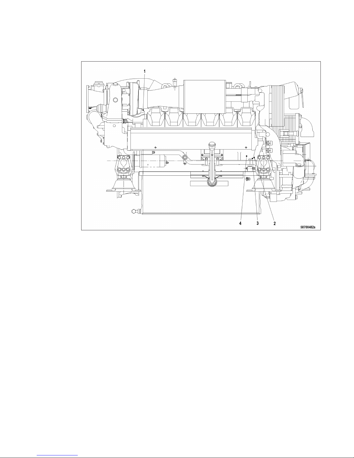
Right engine side 12V 2000 M
1 B44 (N-turbocharger)
2 B16 (P-Coolant)
3 F46 (H-Leak-off fuel)
4 B33 (T-Fuel)
MW15550/07E 2013-01 | General Information | 35
TIM-ID: 0000012937 - 003
Page 36
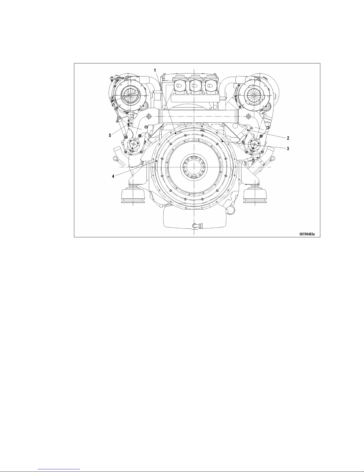
Driving end 12V 2000 M
1 B01 (N-Camshaft)
2 B4.22 (T-Exhaust bulk, B
side)
3 B13 (N-Crankshaft)
4 B13.2 (N-Crankshaft)
5 B4.21 (T-Exhaust bulk, A
side)
36 | General Information | MW15550/07E 2013-01
TIM-ID: 0000012937 - 003
Page 37
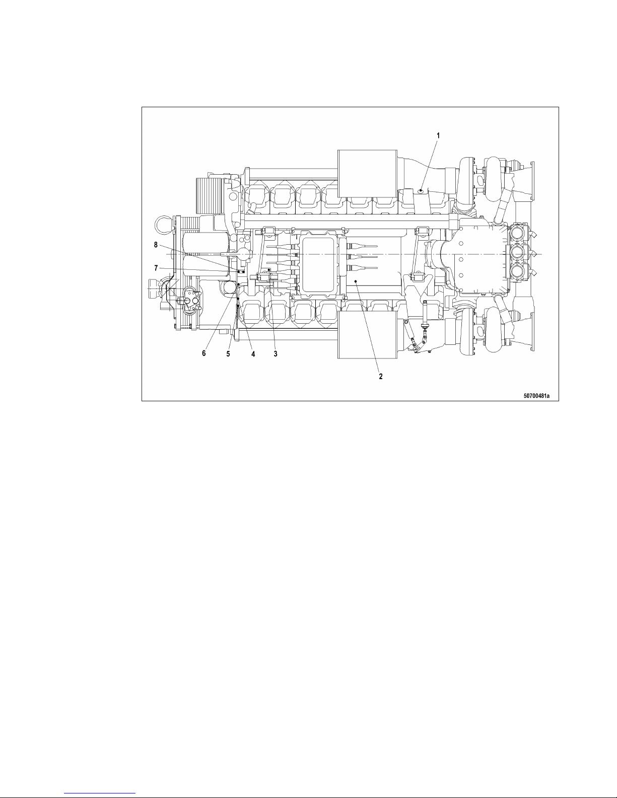
Top view 16V 2000 M
1 B03 (T-Intake air)
2 B10 (P-Charge air)
3 B09 (T-Charge air)
4 B5.2 (P-Lube oil)
5 F25 (P-Lube-oil difference
over filter)
6 B34 (P-Fuel after filter)
7 B07 (T-Lube oil)
8 B05 (P-Lube oil)
MW15550/07E 2013-01 | General Information | 37
TIM-ID: 0000012937 - 003
Page 38
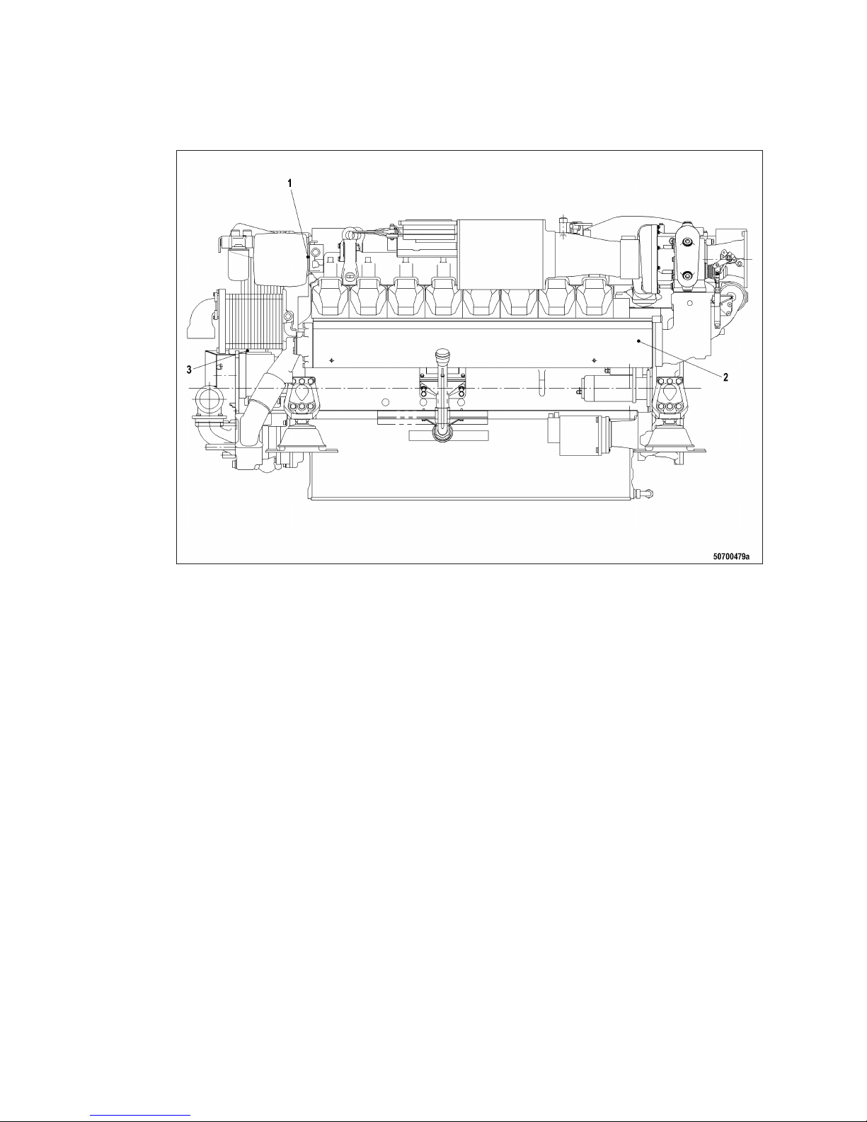
Left engine side 16V 2000 M
1 F33 (H-Coolant) 2 Y27 (Turbocharger control
valve)
3 B21 (Raw water pressure)
38 | General Information | MW15550/07E 2013-01
TIM-ID: 0000012937 - 003
Page 39
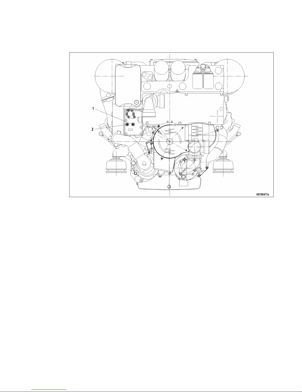
Free end 16V 2000 M
1 B06 (T-Coolant) 2 B6.2 (T-Coolant)
MW15550/07E 2013-01 | General Information | 39
TIM-ID: 0000012937 - 003
Page 40
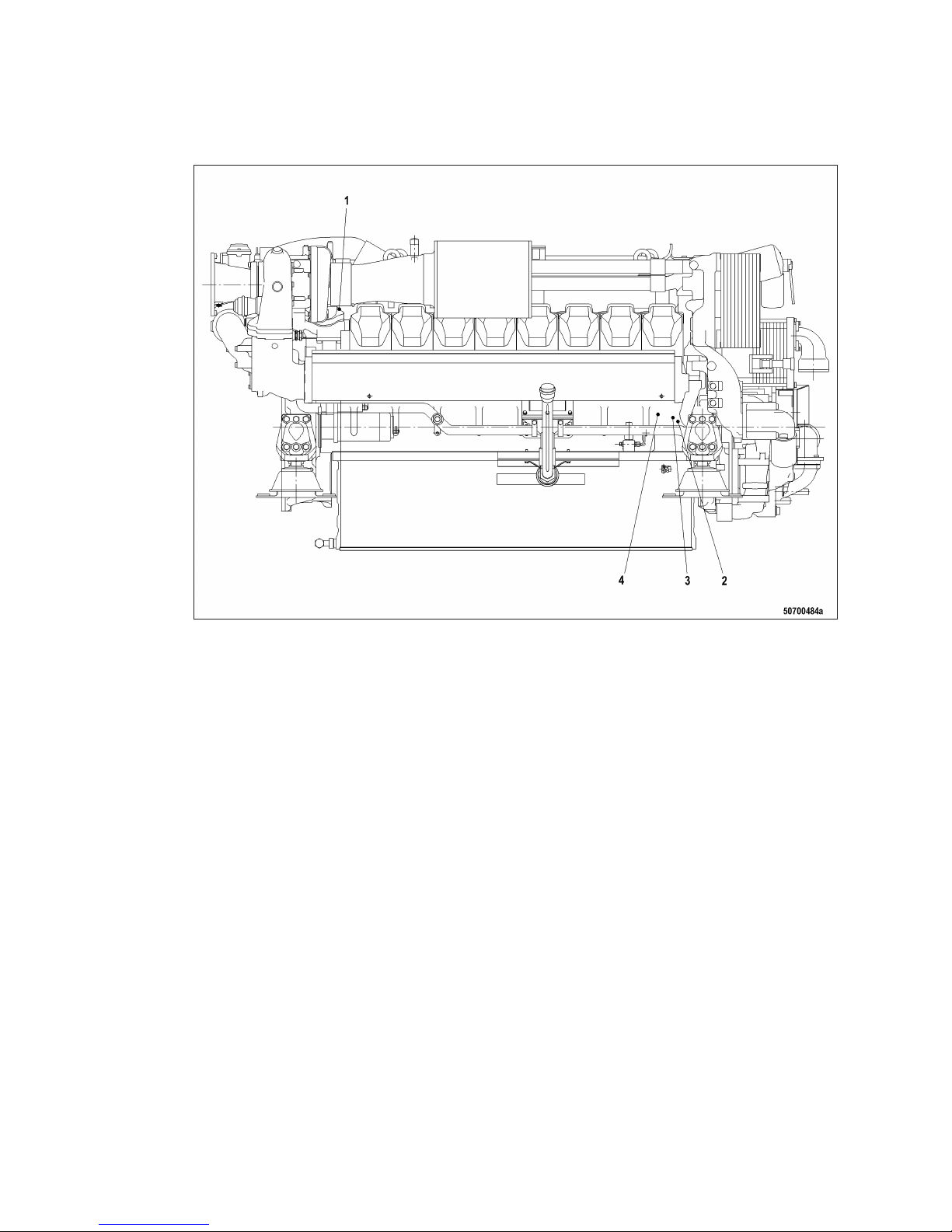
Right engine side 16V 2000 M
1 B44 (N-Turbocharger)
2 B16 (P-Coolant)
3 F46 (H-Leak-off fuel)
4 B33 (T-Fuel)
40 | General Information | MW15550/07E 2013-01
TIM-ID: 0000012937 - 003
Page 41
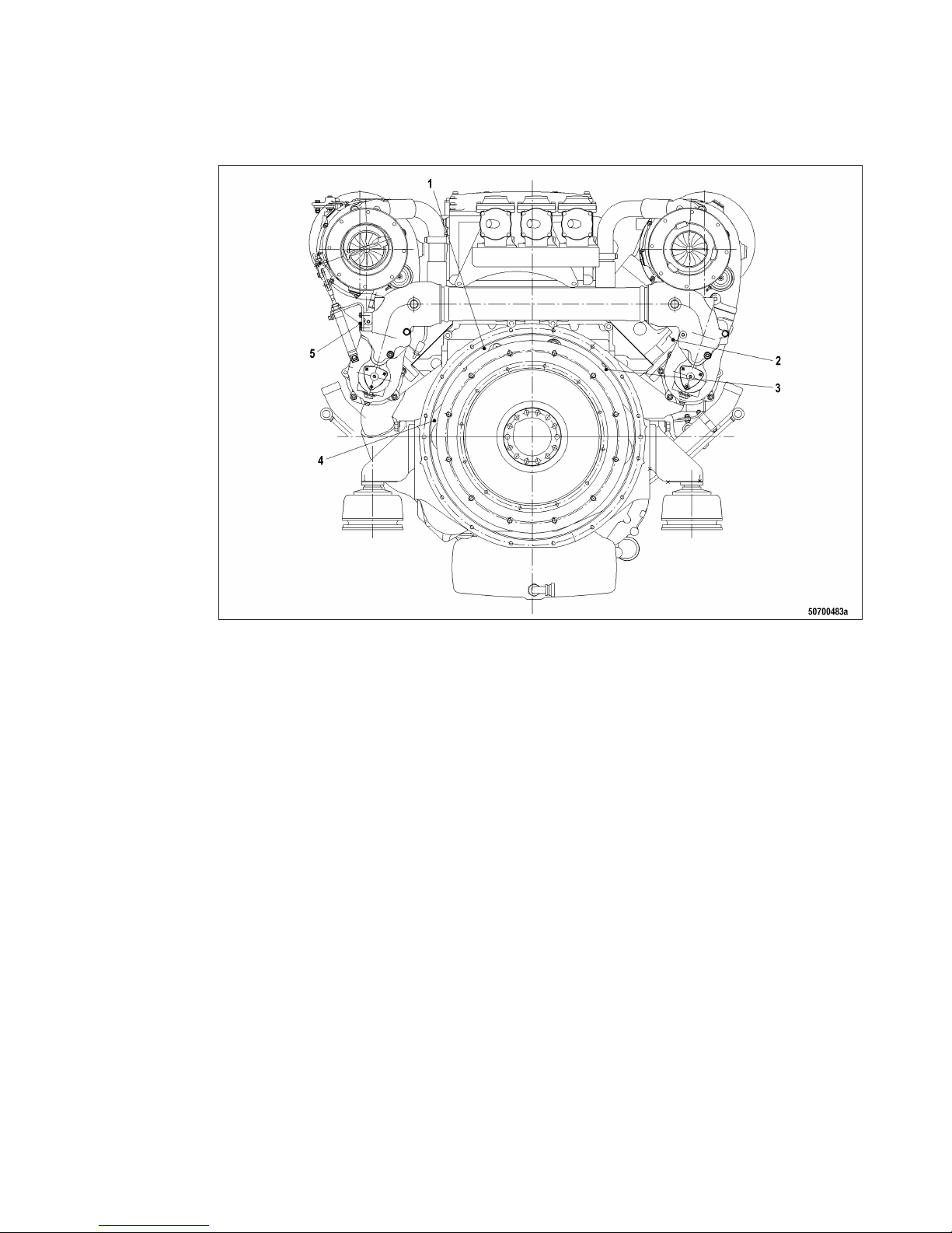
Driving end 16V 2000 M
1 B01 (N-Camshaft)
2 B4.22 (T-Exhaust bulk, B
side)
3 B13 (N-Crankshaft)
4 B13.2 (N-Crankshaft)
5 B4.21 (T-Exhaust bulk, A
side)
MW15550/07E 2013-01 | General Information | 41
TIM-ID: 0000012937 - 003
Page 42
3 Technical Data
3.1 8V 2000 M50A engine data: Engine-mounted heat exchanger,
reference condition: Intake-air temperature 25 °C
Explanation
Abbrev. Meaning
DL Reference value: Continuous power
BL Reference value: Fuel stop power
A Design value
G Guaranteed value
R Guideline value
L Limit value, up to which the engine can be operated, without change (e.g. of power setting)
N Not yet defined value
- Not applicable
X Applicable
Reference conditions
Engine model 8V2000M
50A
Application group 3A
Intake-air temperature °C 25
Raw water inlet temperature °C 25
Barometric pressure mbar 1000
Site altitude above sea level m 100
Power-related data (power ratings are net brake power to ISO 3046)
Number of cylinders 8
Rated engine speed A rpm 1500
Continuous power ISO 3046 (10% overload capability, design power DIN 6280,
ISO 8528)
A kW 332
General conditions (for maximum power)
Number of cylinders 8
Intake depression (new filter) A mbar 15
Intake depression, max. L mbar 50
Model related data (basic design)
Number of cylinders 8
Cylinder arrangement: V angle Degrees 90
Bore mm 130
Stroke mm 150
42 | Technical Data | MW15550/07E 2013-01
TIM-ID: 0000002877 - 002
Page 43
Number of cylinders 8
Displacement of a cylinder Liters 1.99
Displacement, total Liters 15.92
Number of inlet valves per cylinder 2
Number of exhaust valves per cylinder 2
Raw water circuit (open circuit)
Number of cylinders 8
Raw water pump: Inlet pressure, min. L bar -0.2
Raw water pump: inlet pressure, max. L bar +0.5
Pressure loss in engine-external raw water system, max. L bar 1.0
Lube oil system
Number of cylinders 8
Lube oil operating temperature before engine, from R °C 70
Lube-oil operating temperature before engine, to R °C 75
Lube oil operating pressure upstream of engine, from R bar 4.8
Lube oil operating pressure upstream of engine, to R bar 5.3
Lube oil operating pressure (low idle) (meas. point: before engine) R bar 2.0
Fuel system
Number of cylinders 8
Fuel pressure at engine inlet connection, min. (when engine is starting) L bar -0.3
Fuel pressure at supply connection to engine, min. (when engine is running), L bar -0.3
Fuel pressure at supply connection to engine (when engine is starting), max. L bar +0.5
Fuel supply flow, max. R Liters/
min
1.2
General operating data
Number of cylinders 8
Firing speed, from R rpm 100
Firing speed, to R rpm 120
Starter (electric)
Number of cylinders 8
Rated starter voltage (standard design) R V= 24
Starting equipment (air starter)
Number of cylinders 8
Starting-air pressure before starter motor, min. R bar 18
Starting-air pressure before starter motor, max. R bar 30
MW15550/07E 2013-01 | Technical Data | 43
TIM-ID: 0000002877 - 002
Page 44
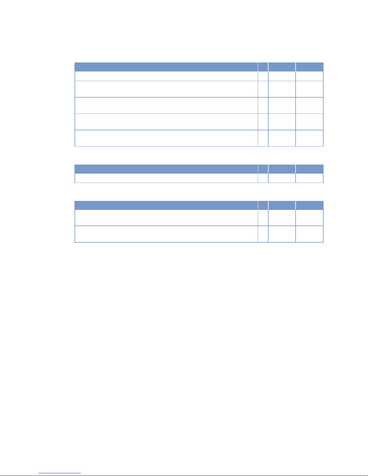
Capacities
Number of cylinders 8
Engine coolant, engine side (with cooling system) R Liters 70
Engine oil capacity, initial filling (standard oil system) (Option: max. operating
inclinations)
R Liters 65
Oil change quantity, max. (standard oil system) (Option: max. operating inclinations)
R Liters 60
Oil pan capacity at dipstick mark “min.” (standard oil system) (Option: max.
operating inclinations)
L Liters 45
Oil pan capacity at dipstick mark “max.” (standard oil system) (Option: max.
operating inclinations)
L Liters 55
Weights / main dimensions
Number of cylinders 8
Engine dry weight (with attached standard accessories, without coupling) R kg 1790
Acoustics
Number of cylinders 8
Exhaust noise, unsilenced, DL, (free-field sound pressure level Lp, 1 m distance, ISO 6798)
R dB(A) 103
Engine surface noise with attenuated intake noise (filter) – DL (free-field
sound-pressure level Lp, 1 m distance, ISO 6798)
R dB(A) 100
44 | Technical Data | MW15550/07E 2013-01
TIM-ID: 0000002877 - 002
Page 45
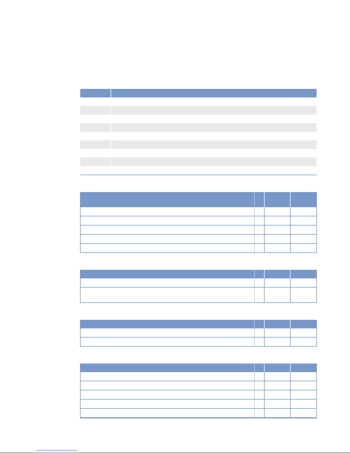
3.2 8V 2000 M50A engine data: Remote heat exchanger,
reference condition: Intake-air temperature 25 °C
Explanation
Abbrev. Meaning
DL Reference value: Continuous power
BL Reference value: Fuel stop power
A Design value
G Guaranteed value
R Guideline value
L Limit value, up to which the engine can be operated, without change (e.g. of power setting)
N Not yet defined value
- Not applicable
X Applicable
Reference conditions
Engine model 8V2000M
50A
Application group 3A
Intake-air temperature °C 25
Raw water inlet temperature °C 25
Barometric pressure mbar 1000
Site altitude above sea level m 100
Power-related data (power ratings are net brake power to ISO 3046)
Number of cylinders 8
Rated engine speed A rpm 1500
Continuous power ISO 3046 (10% overload capability, design power DIN 6280,
ISO 8528)
A kW 332
General conditions (for maximum power)
Number of cylinders 8
Intake depression (new filter) A mbar 15
Intake depression, max. L mbar 50
Model related data (basic design)
Number of cylinders 8
Cylinder arrangement: V angle Degrees 90
Bore mm 130
Stroke mm 150
Displacement of a cylinder Liters 1.99
Displacement, total Liters 15.92
MW15550/07E 2013-01 | Technical Data | 45
TIM-ID: 0000002926 - 002
Page 46
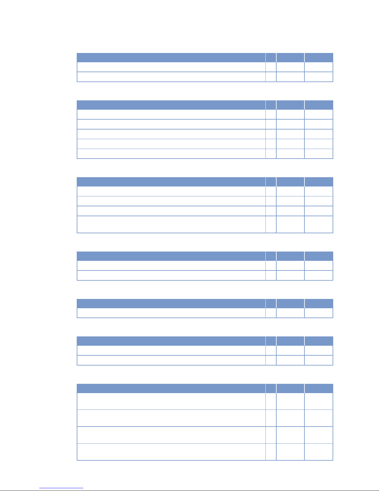
Number of cylinders 8
Number of inlet valves per cylinder 2
Number of exhaust valves per cylinder 2
Lube oil system
Number of cylinders 8
Lube oil operating temperature before engine, from R °C 70
Lube-oil operating temperature before engine, to R °C 75
Lube oil operating pressure upstream of engine, from R bar 4.8
Lube oil operating pressure upstream of engine, to R bar 5.3
Lube oil operating pressure (low idle) (meas. point: before engine) R bar 2.0
Fuel system
Number of cylinders 8
Fuel pressure at engine inlet connection, min. (when engine is starting) L bar -0.3
Fuel pressure at supply connection to engine, min. (when engine is running) L bar -0.3
Fuel pressure at supply connection to engine (when engine is starting), max. L bar +0.5
Fuel supply flow, max. R Liters/
min
10
General operating data
Number of cylinders 8
Firing speed, from R rpm 100
Firing speed, to R rpm 120
Starter (electric)
Number of cylinders 8
Rated starter voltage (standard design) R V= 24
Starting equipment (air starter)
Number of cylinders 8
Starting-air pressure before starter motor, min. R bar 18
Starting-air pressure before starter motor, max. R bar 30
Capacities
Number of cylinders 8
Engine oil capacity, initial filling (standard oil system) (Option: max. operating
inclinations)
R Liters 65
Oil change quantity, max. (standard oil system) (Option: max. operating inclinations)
R Liters 60
Oil pan capacity at dipstick mark “min.” (standard oil system) (Option: max.
operating inclinations)
L Liters 45
Oil pan capacity at dipstick mark “max.” (standard oil system) (Option: max.
operating inclinations)
L Liters 55
46 | Technical Data | MW15550/07E 2013-01
TIM-ID: 0000002926 - 002
Page 47
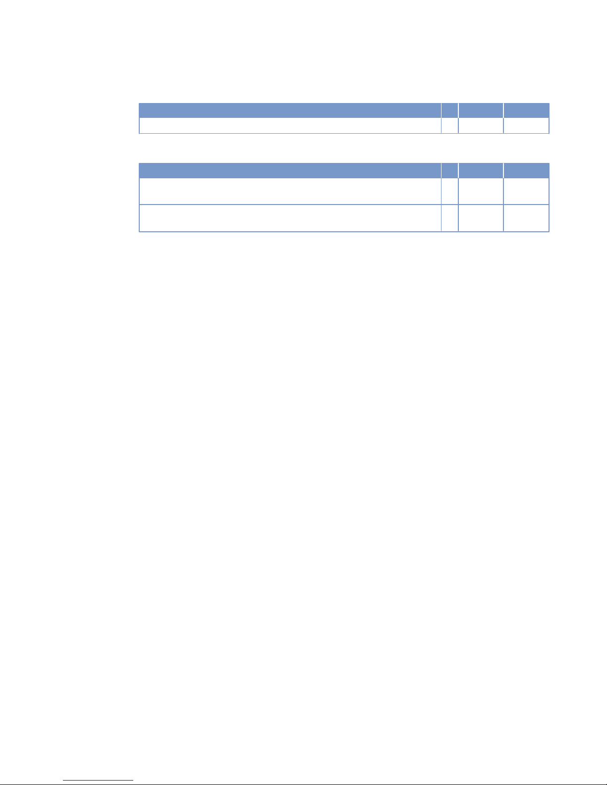
Weights / main dimensions
Number of cylinders 8
Engine dry weight (with attached standard accessories, without coupling) R kg 1750
Acoustics
Number of cylinders 8
Exhaust noise, unsilenced, DL, (free-field sound pressure level Lp, 1 m distance, ISO 6798)
R dB(A) 103
Engine surface noise with attenuated intake noise (filter) – DL (free-field
sound-pressure level Lp, 1 m distance, ISO 6798)
R dB(A) 100
MW15550/07E 2013-01 | Technical Data | 47
TIM-ID: 0000002926 - 002
Page 48
3.3 8V 2000 M50B engine data: Engine-mounted heat exchanger,
reference condition: Intake-air temperature 25 °C
Explanation
Abbrev. Meaning
DL Reference value: Continuous power
BL Reference value: Fuel stop power
A Design value
G Guaranteed value
R Guideline value
L Limit value, up to which the engine can be operated, without change (e.g. of power setting)
N Not yet defined value
- Not applicable
X Applicable
Reference conditions
Engine model 8V2000M
50B
Application group 3A
Intake-air temperature °C 25
Raw-water inlet temperature °C 25
Barometric pressure mbar 1000
Site altitude above sea level m 100
Power-related data (power ratings are net brake power to ISO 3046)
Number of cylinders 8
Rated engine speed A rpm 1800
Continuous power ISO 3046 (10% overload capability, design power DIN 6280,
ISO 8528)
A kW 400
General conditions (for maximum power)
Number of cylinders 8
Intake depression (new filter) A mbar 15
Intake depression, max. L mbar 50
Model related data (basic design)
Number of cylinders 8
Cylinder arrangement: V angle Degrees 90
Bore mm 130
Stroke mm 150
Displacement of a cylinder Liters 1.99
Displacement, total Liters 15.92
48 | Technical Data | MW15550/07E 2013-01
TIM-ID: 0000003065 - 002
Page 49
Number of cylinders 8
Number of inlet valves per cylinder 2
Number of exhaust valves per cylinder 2
Raw water circuit (open circuit)
Number of cylinders 8
Raw water pump: Inlet pressure, min. L bar -0.2
Raw water pump: inlet pressure, max. L bar +0.5
Pressure loss in engine-external raw water system, max. L bar 1.0
Lube oil system
Number of cylinders 8
Lube oil operating temperature before engine, from R °C 75
Lube-oil operating temperature before engine, to R °C 80
Lube oil operating pressure before engine, from R bar 5.6
Lube oil operating pressure before engine, to R bar 6.1
Lube oil operating pressure (low idle) (meas. point: before engine) R bar 2.0
Fuel system
Number of cylinders 8
Fuel pressure at engine inlet connection, min. (when engine is starting) L bar -0.3
Fuel pressure at supply connection to engine, min. (when engine is running) L bar -0.3
Fuel pressure at supply connection to engine (when engine is starting), max. L bar +0.5
Fuel supply flow, max. R Liters/
min
1.4
General operating data
Number of cylinders 8
Firing speed, from R rpm 100
Firing speed, to R rpm 120
Starter (electric)
Number of cylinders 8
Rated starter voltage (standard design) R V= 24
Starting equipment (with air starter motor)
Number of cylinders 8
Starting-air pressure before starter motor, min. R bar 18
Starting-air pressure before starter motor, max. R bar 30
MW15550/07E 2013-01 | Technical Data | 49
TIM-ID: 0000003065 - 002
Page 50
Capacities
Number of cylinders 8
Engine coolant, engine side (with cooling system) R Liters 70
Engine oil capacity, initial filling (standard oil system) (Option: max. operating
inclinations)
R Liters 65
Oil change quantity, max. (standard oil system) (Option: max. operating inclinations)
R Liters 60
Oil pan capacity at dipstick mark “min.” (standard oil system) (Option: max.
operating inclinations)
L Liters 45
Oil pan capacity at dipstick mark “max.” (standard oil system) (Option: max.
operating inclinations)
L Liters 55
Weights / main dimensions
Number of cylinders 8
Engine dry weight (with attached standard accessories, without coupling) R kg 1790
Acoustics
Number of cylinders 8
Exhaust noise, unsilenced, DL, (free-field sound pressure level Lp, 1 m distance, ISO 6798)
R dB(A) 104
Engine surface noise with attenuated intake noise (filter) – DL (free-field
sound-pressure level Lp, 1 m distance, ISO 6798)
R dB(A) 99
50 | Technical Data | MW15550/07E 2013-01
TIM-ID: 0000003065 - 002
Page 51
3.4 8V 2000 M50B engine data: Remote heat exchanger,
reference condition: Intake-air temperature 25 °C
Explanation
Abbrev. Meaning
DL Reference value: Continuous power
BL Reference value: Fuel stop power
A Design value
G Guaranteed value
R Guideline value
L Limit value, up to which the engine can be operated, without change (e.g. of power setting)
N Not yet defined value
- Not applicable
X Applicable
Reference conditions
Engine model 8V2000M
50B
Application group 3A
Intake-air temperature °C 25
Raw water inlet temperature °C 25
Barometric pressure mbar 1000
Site altitude above sea level m 100
Power-related data (power ratings are net brake power to ISO 3046)
Number of cylinders 8
Rated engine speed A rpm 1800
Continuous power ISO 3046 (10% overload capability, design power DIN 6280,
ISO 8528)
A kW 400
General conditions (for maximum power)
Number of cylinders 8
Intake depression (new filter) A mbar 15
Intake depression, max. L mbar 50
Model related data (basic design)
Number of cylinders 8
Cylinder arrangement: V angle Degrees 90
Bore mm 130
Stroke mm 150
Displacement of a cylinder Liters 1.99
Displacement, total Liters 15.92
MW15550/07E 2013-01 | Technical Data | 51
TIM-ID: 0000003072 - 002
Page 52
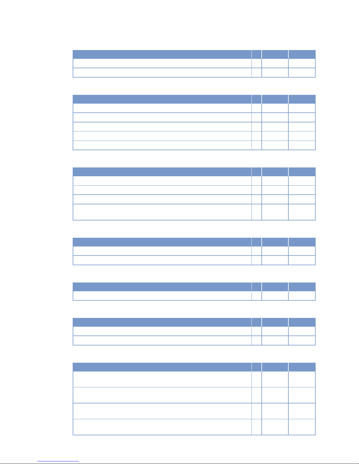
Number of cylinders 8
Number of inlet valves per cylinder 2
Number of exhaust valves per cylinder 2
Lube oil system
Number of cylinders 8
Lube oil operating temperature before engine, from R °C 75
Lube-oil operating temperature before engine, to R °C 80
Lube oil operating pressure before engine, from R bar 5.6
Lube oil operating pressure before engine, to R bar 6.1
Lube oil operating pressure (low idle) (meas. point: before engine) R bar 2.0
Fuel system
Number of cylinders 8
Fuel pressure at engine inlet connection, min. (when engine is starting) L bar -0.3
Fuel pressure at supply connection to engine, min. (when engine is running) L bar -0.3
Fuel pressure at supply connection to engine (when engine is starting), max. L bar +0.5
Fuel supply flow, max. R Liters/
min
11.9
General operating data
Number of cylinders 8
Firing speed, from R rpm 100
Firing speed, to R rpm 120
Starter (electric)
Number of cylinders 8
Rated starter voltage (standard design) R V= 24
Starting equipment (with air starter motor)
Number of cylinders 8
Starting-air pressure before starter motor, min. R bar 18
Starting-air pressure before starter motor, max. R bar 30
Capacities
Number of cylinders 8
Engine oil capacity, initial filling (standard oil system) (Option: max. operating
inclinations)
R Liters 65
Oil change quantity, max. (standard oil system) (Option: max. operating inclinations)
R Liters 60
Oil pan capacity at dipstick mark “min.” (standard oil system) (Option: max.
operating inclinations)
L Liters 45
Oil pan capacity at dipstick mark “max.” (standard oil system) (Option: max.
operating inclinations)
L Liters 55
52 | Technical Data | MW15550/07E 2013-01
TIM-ID: 0000003072 - 002
Page 53
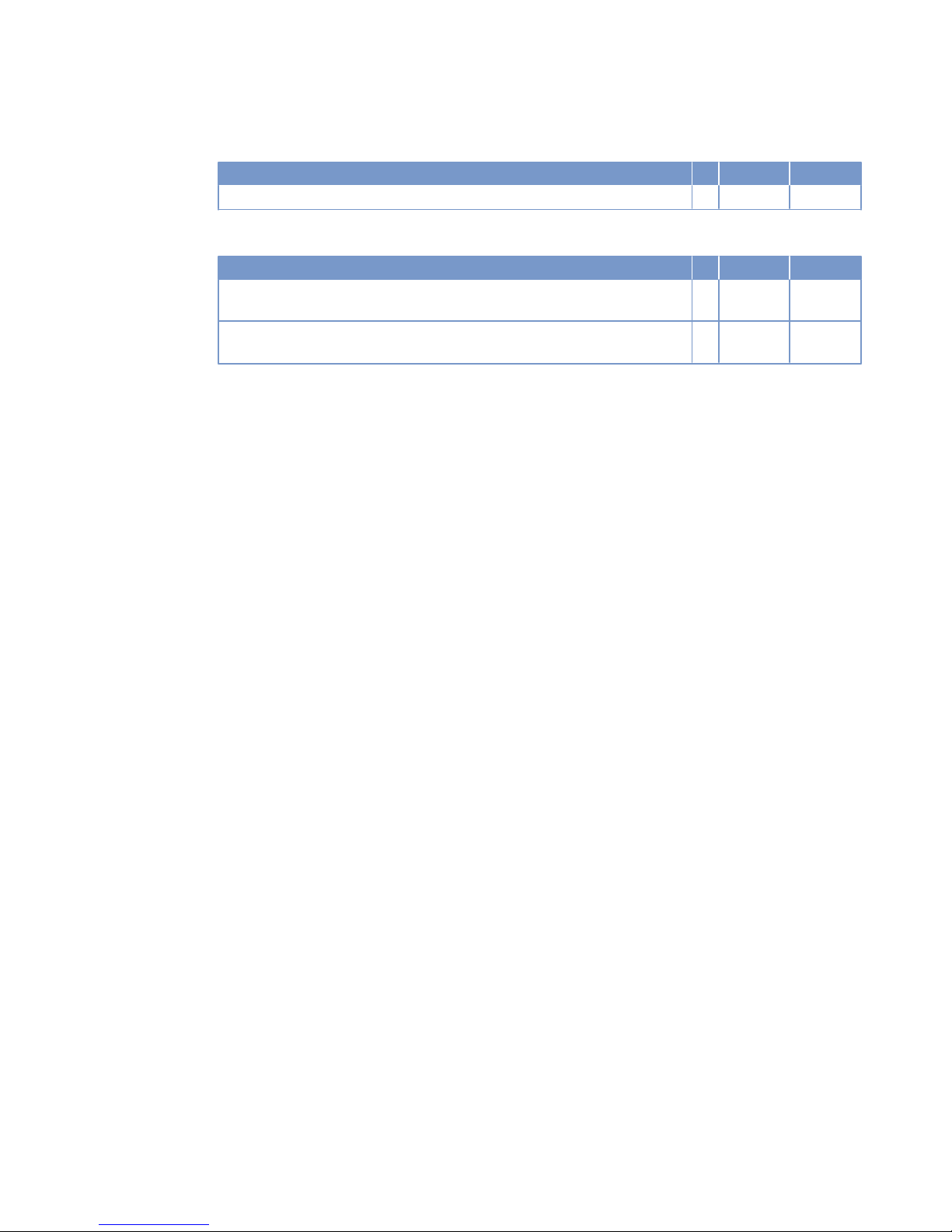
Weights / main dimensions
Number of cylinders 8
Engine dry weight (with attached standard accessories, without coupling) R kg 1750
Acoustics
Number of cylinders 8
Exhaust noise, unsilenced, DL, (free-field sound pressure level Lp, 1 m distance, ISO 6798)
R dB(A) 104
Engine surface noise with attenuated intake noise (filter) – DL (free-field
sound-pressure level Lp, 1 m distance, ISO 6798)
R dB(A) 99
MW15550/07E 2013-01 | Technical Data | 53
TIM-ID: 0000003072 - 002
Page 54
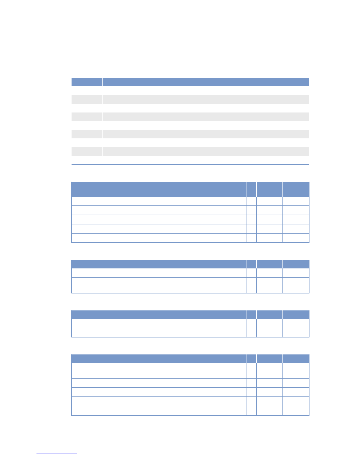
3.5 Engine data 8V 2000M51A, engine-mounted heat exchanger
Explanation
Abbrev. Meaning
DL Reference value: Continuous power
BL Reference value: Fuel stop power
A Design value
G Guaranteed value
R Guideline value
L Limit value, up to which the engine can be operated, without change (e.g. of power setting)
N Not yet defined value
- Not applicable
X Applicable
Reference conditions
Engine model 8V2000M
51A
Application group 3A
Intake-air temperature °C 25
Raw water inlet temperature °C 25
Barometric pressure mbar 1000
Site altitude above sea level m 100
Power-related data (power ratings are net brake power to ISO 3046)
Number of cylinders 8
Rated engine speed A rpm 1500
Continuous power ISO 3046 (10% overload capability, design power DIN 6280,
ISO 8528)
A kW 332
General conditions (for maximum power)
Number of cylinders 8
Intake depression (new filter) A mbar 15
Intake depression, max. L mbar 50
Model related data (basic design)
Number of cylinders 8
Cylinder arrangement: V angle Degrees
(°)
90
Bore mm 130
Stroke mm 150
Displacement of a cylinder Liters 1.99
Displacement, total Liters 15.92
54 | Technical Data | MW15550/07E 2013-01
TIM-ID: 0000036350 - 001
Page 55
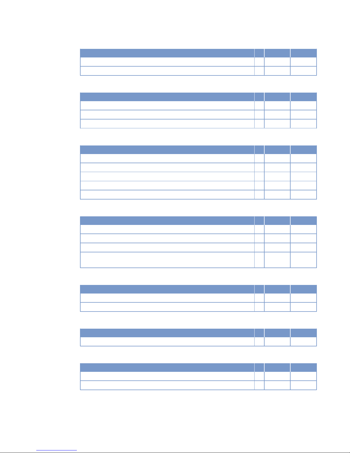
Number of cylinders 8
Number of inlet valves per cylinder 2
Number of exhaust valves per cylinder 2
Raw water circuit (open circuit)
Number of cylinders 8
Raw water pump: Inlet pressure, min. L bar -0.2
Raw water pump: inlet pressure, max. L bar 0.5
Pressure loss in off-engine raw water system, max. permissible. L bar 1.0
Lube oil system
Number of cylinders 8
Lube oil operating temperature before engine, from R °C 70
Lube oil operating temperature before engine, to R °C 75
Lube oil operating pressure before engine, from R bar 4.8
Lube oil operating pressure before engine, to R bar 5.3
Lube oil operating pressure (low idle) (meas. point: before engine) R bar 2.0
Fuel system
Number of cylinders 8
Fuel pressure at engine inlet connection, min. (when engine is starting) L bar -0.3
Fuel pressure at engine inlet connection, min. (when engine is running) L bar -0.3
Fuel pressure at engine inlet connection, max. (when engine is starting) L bar 0.5
Fuel supply flow, max. A Liters/
min
1.45
General operating data
Number of cylinders 8
Firing speed, from R rpm 100
Firing speed, to R rpm 120
Starter (electric)
Number of cylinders 8
Starter rated voltage (standard design) R V= 24
Starting equipment (with compressed air/hydraulic starter motor)
Number of cylinders 8
Starting-air pressure before starter motor, min. R bar 18*
Starting-air pressure before starter motor, max. R bar 30
MW15550/07E 2013-01 | Technical Data | 55
TIM-ID: 0000036350 - 001
Page 56
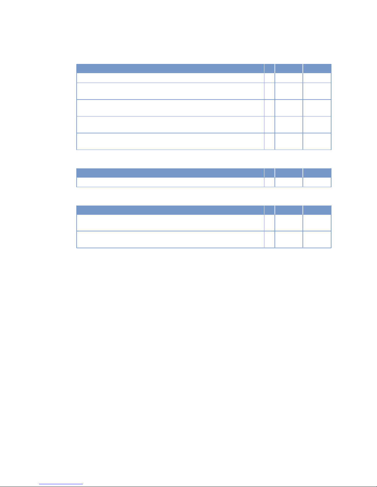
Capacities
Number of cylinders 8
Engine coolant, engine side (with cooling system) R Liters 70
Engine oil capacity, initial filling (standard oil system) (Option: max. operating
inclinations)
R Liters 65
Oil change quantity, max. (standard oil system) (option: max. operating inclinations)
R Liters 60
Oil pan capacity at dipstick mark “min.” (standard oil system) (Option: max.
operating inclinations)
L Liters 45
Oil pan capacity at dipstick mark “max.” (standard oil system) (Option: max.
operating inclinations)
L Liters 55
Weights / main dimensions
Number of cylinders 8
Engine dry weight (with standard accessories installed, w/o coupling) R kg 1790
Acoustics
Number of cylinders 8
Exhaust noise, unsilenced – DL (free-field sound pressure level Lp, 1 m distance, ISO 6798, +3dB(A) tolerance)
R dB(A) 103
Engine surface noise with attenuated intake noise (filter) – DL (free-field sound
power level Lp, 1 m distance, ISO 6798, +2dB(A) tolerance)
R dB(A) 100
56 | Technical Data | MW15550/07E 2013-01
TIM-ID: 0000036350 - 001
Page 57
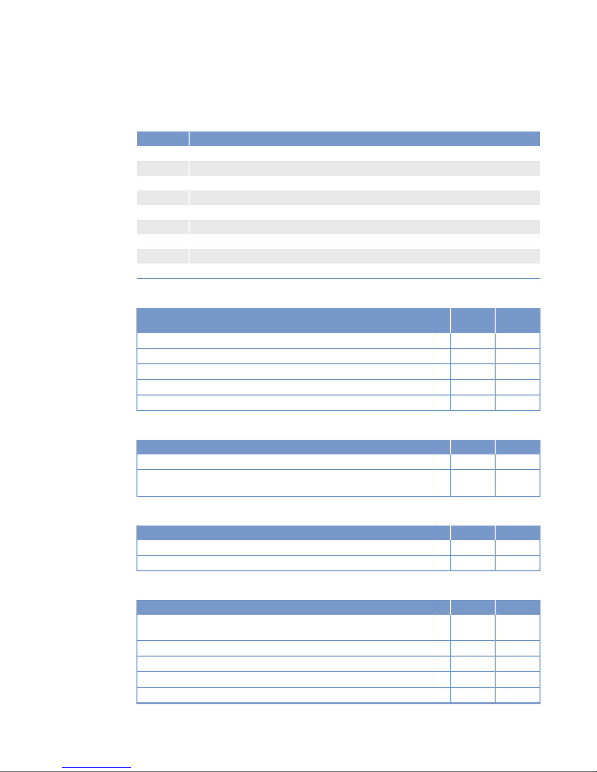
3.6 8V 2000 M51A engine data: Remote heat exchanger
Explanation
Abbrev. Meaning
DL Reference value: Continuous power
BL Reference value: Fuel stop power
A Design value
G Guaranteed value
R Guideline value
L Limit value, up to which the engine can be operated, without change (e.g. of power setting)
N Not yet defined value
- Not applicable
X Applicable
Reference conditions
Engine model 8V2000M
51A
Application group 3A
Intake-air temperature °C 25
Raw water inlet temperature °C 25
Barometric pressure mbar 1000
Site altitude above sea level m 100
Power-related data (power ratings are net brake power as per ISO 3046)
Number of cylinders 8
Rated engine speed A rpm 1500
Continuous power ISO 3046 (10% overload capability, design power DIN 6280,
ISO 8528)
A kW 332
General conditions (for maximum power)
Number of cylinders 8
Intake depression (new filter) A mbar 15
Intake depression, max. L mbar 50
Model related data (basic design)
Number of cylinders 8
Cylinder arrangement: V angle Degrees
(°)
90
Bore mm 130
Stroke mm 150
Displacement of a cylinder Liters 1.99
Displacement, total Liters 15.92
MW15550/07E 2013-01 | Technical Data | 57
TIM-ID: 0000036349 - 001
Page 58
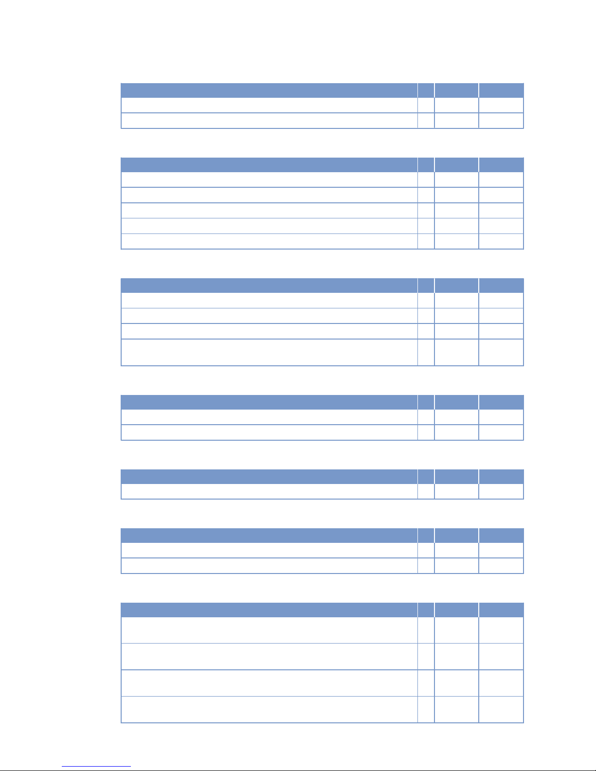
Number of cylinders 8
Number of inlet valves per cylinder 2
Number of exhaust valves per cylinder 2
Lube oil system
Number of cylinders 8
Lube oil operating temperature before engine, from R °C 70
Lube oil operating temperature before engine, to R °C 75
Lube oil operating pressure before engine, from R bar 4.8
Lube oil operating pressure before engine, to R bar 5.3
Lube oil operating pressure (low idle) (meas. point: before engine) R bar 2.0
Fuel system
Number of cylinders 8
Fuel pressure at engine inlet connection, min. (when engine is starting) L bar -0.3
Fuel pressure at engine inlet connection, min. (when engine is running) L bar -0.3
Fuel pressure at engine inlet connection, max. (when engine is starting) L bar 0.5
Fuel supply flow, max. A Liters/
min
10
General operating data
Number of cylinders 8
Firing speed, from R rpm 100
Firing speed, to R rpm 120
Starter (electric)
Number of cylinders 8
Starter rated voltage (standard design) R V= 24
Starting equipment (with compressed air/hydraulic starter motor)
Number of cylinders 8
Starting-air pressure before starter motor, min. R bar 18*
Starting-air pressure before starter motor, max. R bar 30
Capacities
Number of cylinders 8
Engine oil capacity, initial filling (standard oil system) (Option: max. operating
inclinations)
R Liters 65
Oil change quantity, max. (standard oil system) (option: max. operating inclinations)
R Liters 60
Oil pan capacity at dipstick mark “min.” (standard oil system) (Option: max.
operating inclinations)
L Liters 45
Oil pan capacity at dipstick mark “max.” (standard oil system) (Option: max.
operating inclinations)
L Liters 55
58 | Technical Data | MW15550/07E 2013-01
TIM-ID: 0000036349 - 001
Page 59
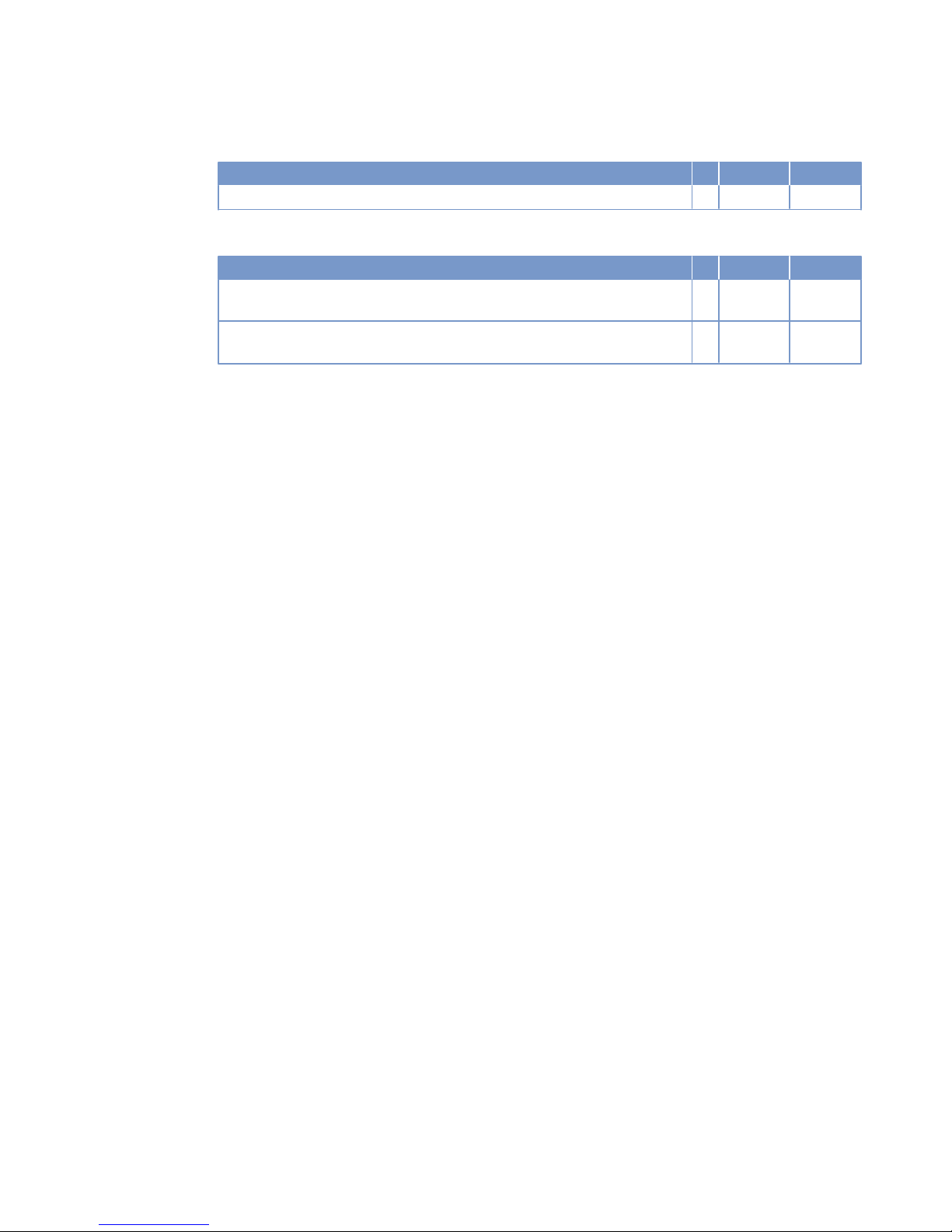
Weights / main dimensions
Number of cylinders 8
Engine dry weight (with standard accessories installed, w/o coupling) R kg 1750
Acoustics
Number of cylinders 8
Exhaust noise, unsilenced – DL (free-field sound pressure level Lp, 1 m distance, ISO 6798, +3dB(A) tolerance)
R dB(A) 103
Engine surface noise with attenuated intake noise (filter) – DL (free-field sound
power level Lp, 1 m distance, ISO 6798, +2dB(A) tolerance)
R dB(A) 100
MW15550/07E 2013-01 | Technical Data | 59
TIM-ID: 0000036349 - 001
Page 60
3.7 Engine data 8V 2000M51B, engine-mounted heat exchanger
Explanation
Abbrev. Meaning
DL Reference value: Continuous power
BL Reference value: Fuel stop power
A Design value
G Guaranteed value
R Guideline value
L Limit value, up to which the engine can be operated, without change (e.g. of power setting)
N Not yet defined value
- Not applicable
X Applicable
Reference conditions
Engine model 8V2000M
51B
Application group 3A
Intake-air temperature °C 25
Raw water inlet temperature °C 25
Barometric pressure mbar 1000
Site altitude above sea level m 100
Power-related data (power ratings are net brake power as per ISO 3046)
Number of cylinders 8
Rated engine speed A rpm 1800
Continuous power ISO 3046 (10% overload capability, design power DIN 6280,
ISO 8528)
A kW 400
General conditions (for maximum power)
Number of cylinders 8
Intake depression (new filter) A mbar 15
Intake depression, max. L mbar 50
Model related data (basic design)
Number of cylinders 8
Cylinder arrangement: V angle Degrees
(°)
90
Bore mm 130
Stroke mm 150
Displacement of a cylinder Liters 1.99
Displacement, total Liters 15.92
60 | Technical Data | MW15550/07E 2013-01
TIM-ID: 0000036352 - 001
Page 61
Number of cylinders 8
Number of inlet valves per cylinder 2
Number of exhaust valves per cylinder 2
Raw water circuit (open circuit)
Number of cylinders 8
Raw water pump: Inlet pressure, min. L bar -0.2
Raw water pump: inlet pressure, max. L bar 0.5
Pressure loss in off-engine raw water system, max. permissible. L bar 1.0
Lube oil system
Number of cylinders 8
Lube oil operating temperature before engine, from R °C 75
Lube-oil operating temperature before engine, to R °C 80
Lube oil operating pressure before engine, from R bar 5.6
Lube oil operating pressure before engine, to R bar 6.1
Lube oil operating pressure (low idle) (meas. point: before engine) R bar 2.0
Fuel system
Number of cylinders 8
Fuel pressure at engine inlet connection, min. (when engine is starting) L bar -0.3
Fuel pressure at engine inlet connection, min. (when engine is running) L bar -0.3
Fuel pressure at engine inlet connection, max. (when engine is starting) L bar 0.5
Fuel supply flow, max. A Liters/
min
1.67
General operating data
Number of cylinders 8
Firing speed, from R rpm 100
Firing speed, to R rpm 120
Starter (electric)
Number of cylinders 8
Starter rated voltage (standard design) R V= 24
Starting equipment (with compressed air/hydraulic starter motor)
Number of cylinders 8
Starting-air pressure before starter motor, min. R bar 18*
Starting-air pressure before starter motor, max. R bar 30
MW15550/07E 2013-01 | Technical Data | 61
TIM-ID: 0000036352 - 001
Page 62
Capacities
Number of cylinders 8
Engine coolant, engine side (with cooling system) R Liters 70
Engine oil capacity, initial filling (standard oil system) (Option: max. operating
inclinations)
R Liters 65
Oil change quantity, max. (standard oil system) (option: max. operating inclinations)
R Liters 60
Oil pan capacity at dipstick mark “min.” (standard oil system) (Option: max.
operating inclinations)
L Liters 45
Oil pan capacity at dipstick mark “max.” (standard oil system) (Option: max.
operating inclinations)
L Liters 55
Weights / main dimensions
Number of cylinders 8
Engine dry weight (with standard accessories installed, w/o coupling) R kg 1790
Acoustics
Number of cylinders 8
Exhaust noise, unsilenced – DL (free-field sound pressure level Lp, 1 m distance, ISO 6798, +3dB(A) tolerance)
R dB(A) 104
Engine surface noise with attenuated intake noise (filter) – DL (free-field sound
power level Lp, 1 m distance, ISO 6798, +2dB(A) tolerance)
R dB(A) 99
62 | Technical Data | MW15550/07E 2013-01
TIM-ID: 0000036352 - 001
Page 63
3.8 8V 2000 M51B engine data: Remote heat exchanger
Explanation
Abbrev. Meaning
DL Reference value: Continuous power
BL Reference value: Fuel stop power
A Design value
G Guaranteed value
R Guideline value
L Limit value, up to which the engine can be operated, without change (e.g. of power setting)
N Not yet defined value
- Not applicable
X Applicable
Reference conditions
Engine model 8V2000M
51B
Application group 3A
Intake-air temperature °C 25
Raw water inlet temperature °C 25
Barometric pressure mbar 1000
Site altitude above sea level m 100
Power-related data (power ratings are net brake power as per ISO 3046)
Number of cylinders 8
Rated engine speed A rpm 1800
Continuous power ISO 3046 (10% overload capability, design power DIN 6280,
ISO 8528)
A kW 400
General conditions (for maximum power)
Number of cylinders 8
Intake depression (new filter) A mbar 15
Intake depression, max. L mbar 50
Model related data (basic design)
Number of cylinders 8
Cylinder arrangement: V angle Degrees
(°)
90
Bore mm 130
Stroke mm 150
Displacement of a cylinder Liters 1.99
Displacement, total Liters 15.92
MW15550/07E 2013-01 | Technical Data | 63
TIM-ID: 0000036351 - 001
Page 64
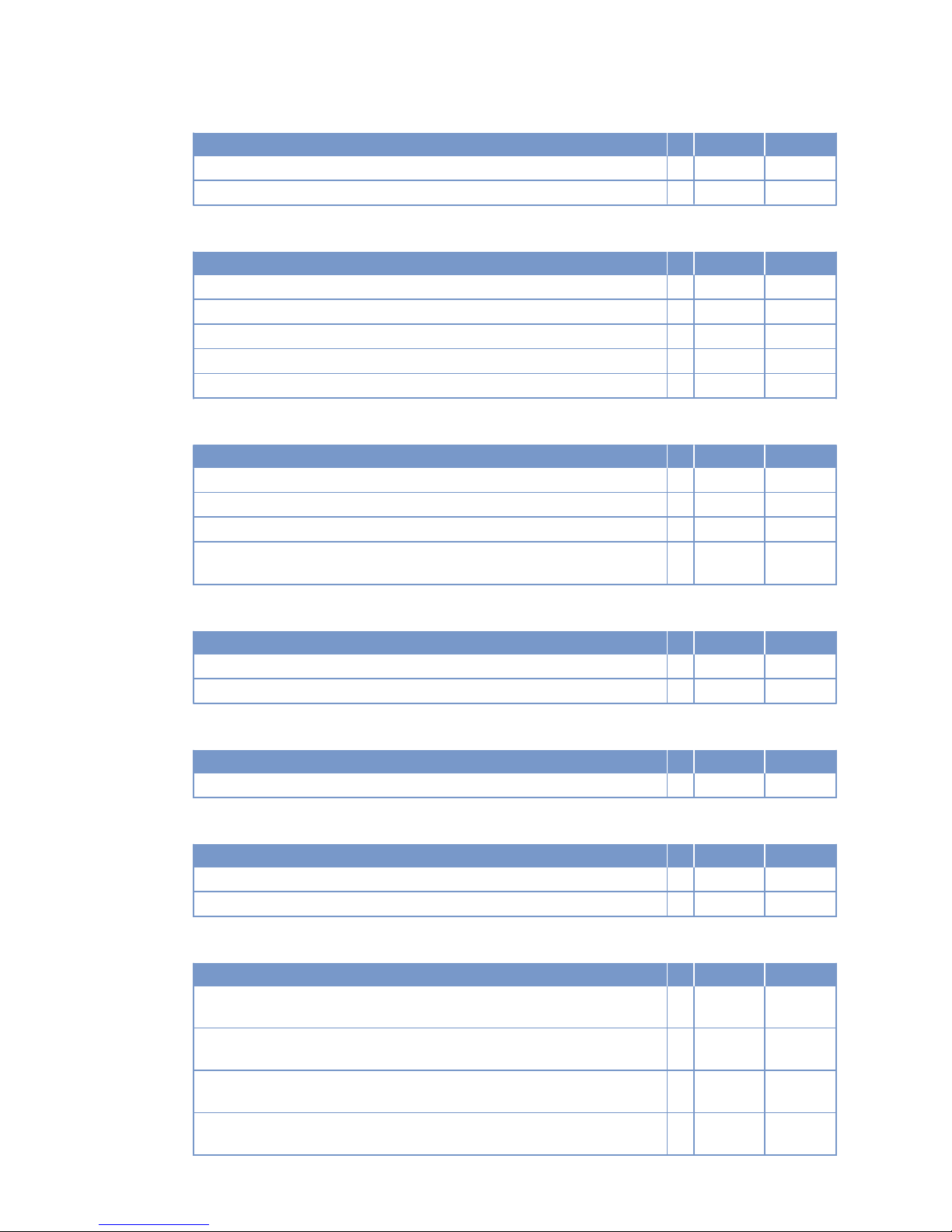
Number of cylinders 8
Number of inlet valves per cylinder 2
Number of exhaust valves per cylinder 2
Lube oil system
Number of cylinders 8
Lube oil operating temperature before engine, from R °C 75
Lube oil operating temperature before engine, to R °C 80
Lube oil operating pressure before engine, from R bar 5.6
Lube oil operating pressure before engine, to R bar 6.1
Lube oil operating pressure (low idle) (meas. point: before engine) R bar 2.0
Fuel system
Number of cylinders 8
Fuel pressure at engine inlet connection, min. (when engine is starting) L bar -0.3
Fuel pressure at engine inlet connection, min. (when engine is running) L bar -0.3
Fuel pressure at engine inlet connection, max. (when engine is starting) L bar 0.5
Fuel supply flow, max. A Liters/
min
12
General operating data
Number of cylinders 8
Firing speed, from R rpm 100
Firing speed, to R rpm 120
Starter (electric)
Number of cylinders 8
Starter rated voltage (standard design) R V= 24
Starting equipment (with compressed air/hydraulic starter motor)
Number of cylinders 8
Starting-air pressure before starter motor, min. R bar 18*
Starting-air pressure before starter motor, max. R bar 30
Capacities
Number of cylinders 8
Engine oil capacity, initial filling (standard oil system) (Option: max. operating
inclinations)
R Liters 65
Oil change quantity, max. (standard oil system) (option: max. operating inclinations)
R Liters 60
Oil pan capacity at dipstick mark “min.” (standard oil system) (Option: max.
operating inclinations)
L Liters 45
Oil pan capacity at dipstick mark “max.” (standard oil system) (Option: max.
operating inclinations)
L Liters 55
64 | Technical Data | MW15550/07E 2013-01
TIM-ID: 0000036351 - 001
Page 65
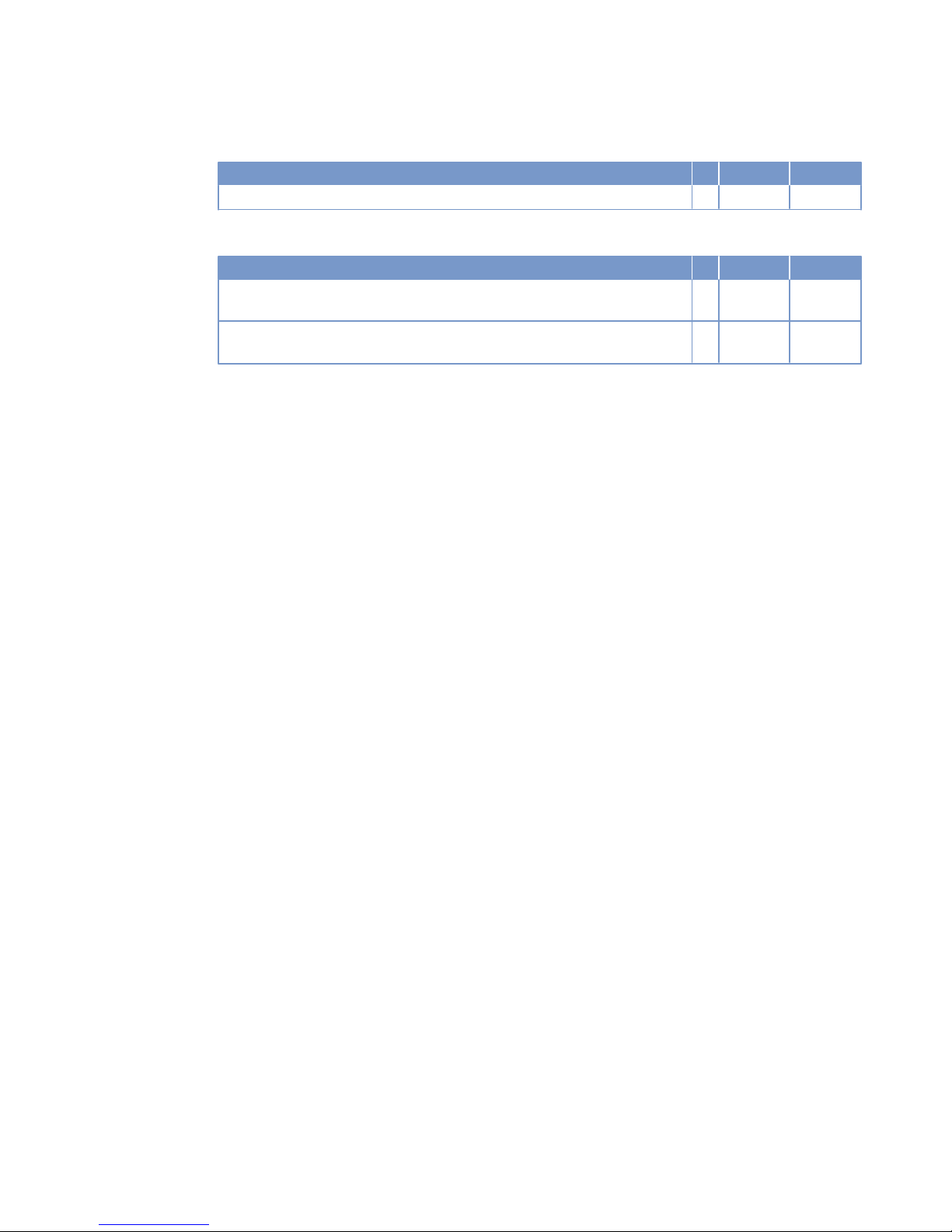
Weights / main dimensions
Number of cylinders 8
Engine dry weight (with standard accessories installed, w/o coupling) R kg 1750
Acoustics
Number of cylinders 8
Exhaust noise, unsilenced – DL (free-field sound pressure level Lp, 1 m distance, ISO 6798, +3dB(A) tolerance)
R dB(A) 104
Engine surface noise with attenuated intake noise (filter) – DL (free-field sound
power level Lp, 1 m distance, ISO 6798, +2dB(A) tolerance)
R dB(A) 99
MW15550/07E 2013-01 | Technical Data | 65
TIM-ID: 0000036351 - 001
Page 66
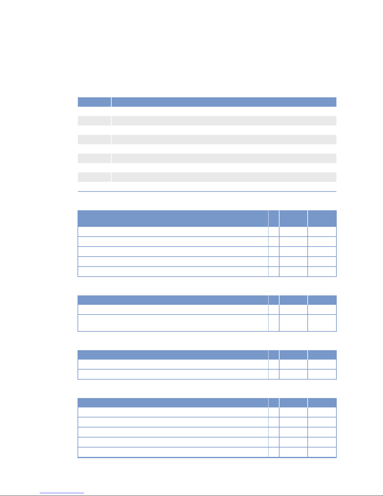
3.9 12V 2000 M50A engine data: Engine-mounted heat
exchanger, reference condition: Intake-air temperature 25 °C
Explanation
Abbrev. Meaning
DL Reference value: Continuous power
BL Reference value: Fuel stop power
A Design value
G Guaranteed value
R Guideline value
L Limit value, up to which the engine can be operated, without change (e.g. of power setting)
N Not yet defined value
- Not applicable
X Applicable
Reference conditions
Engine model 12V2000
M50A
Application group 3A
Intake-air temperature °C 25
Raw water inlet temperature °C 25
Barometric pressure mbar 1000
Site altitude above sea level m 100
Power-related data (power ratings are net brake power to ISO 3046)
Number of cylinders 12
Rated engine speed A rpm 1500
Continuous power ISO 3046 (10% overload capability, design power DIN 6280,
ISO 8528)
A kW 498
General conditions (for maximum power)
Number of cylinders 12
Intake depression (new filter) A mbar 15
Intake depression, max. L mbar 50
Model related data (basic design)
Number of cylinders 12
Cylinder arrangement: V angle Degrees 90
Bore mm 130
Stroke mm 150
Displacement of a cylinder Liters 1.99
Displacement, total Liters 23.88
66 | Technical Data | MW15550/07E 2013-01
TIM-ID: 0000002985 - 002
Page 67
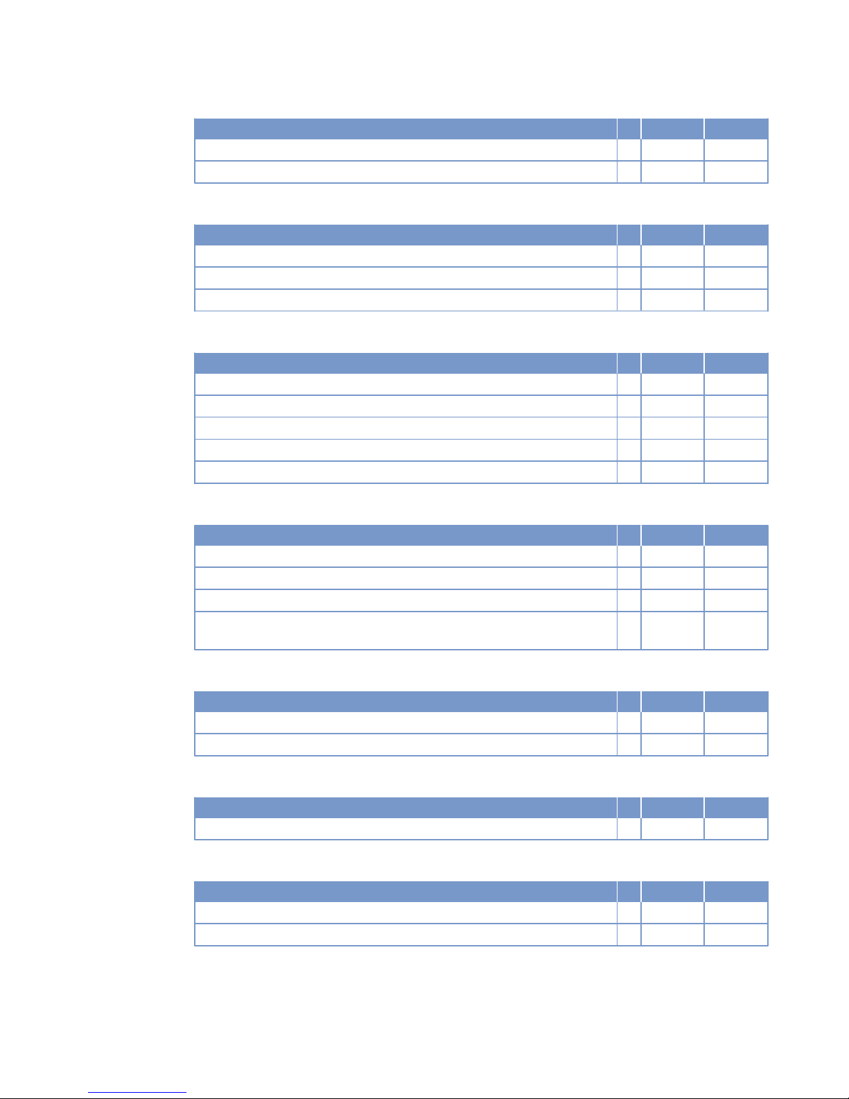
Number of cylinders 12
Number of inlet valves per cylinder 2
Number of exhaust valves per cylinder 2
Raw water circuit (open circuit)
Number of cylinders 12
Raw water pump: Inlet pressure, min. L bar -0.2
Raw water pump: inlet pressure, max. L bar +0.5
Pressure loss in engine-external raw water system, max. L bar 1.0
Lube oil system
Number of cylinders 12
Lube oil operating temperature before engine, from R °C 70
Lube-oil operating temperature before engine, to R °C 75
Lube oil operating pressure before engine, from R bar 7.4
Lube oil operating pressure before engine, to R bar 7.9
Lube oil operating pressure (low idle) (meas. point: before engine) R bar 3.5
Fuel system
Number of cylinders 12
Fuel pressure at engine inlet connection, min. (when engine is starting) L bar -0.3
Fuel pressure at supply connection to engine, min. (when engine is running) L bar -0.3
Fuel pressure at supply connection to engine (when engine is starting), max. L bar +0.5
Fuel supply flow, max. R Liters/
min
2.3
General operating data
Number of cylinders 12
Firing speed, from R rpm 100
Firing speed, to R rpm 120
Starter (electric)
Number of cylinders 12
Rated starter voltage (standard design) R V= 24
Starting equipment (air starter)
Number of cylinders 12
Starting-air pressure before starter motor, min. R bar 21
Starting-air pressure before starter motor, max. R bar 30
MW15550/07E 2013-01 | Technical Data | 67
TIM-ID: 0000002985 - 002
Page 68
Capacities
Number of cylinders 12
Engine coolant, engine side (with cooling system) R Liters 110
Engine oil capacity, initial filling (standard oil system) (Option: max. operating
inclinations)
R Liters 105
Oil change quantity, max. (standard oil system) (Option: max. operating inclinations)
R Liters 98
Oil pan capacity at dipstick mark “min.” (standard oil system) (Option: max.
operating inclinations)
L Liters 73
Oil pan capacity at dipstick mark “max.” (standard oil system) (Option: max.
operating inclinations)
L Liters 88
Weights / main dimensions
Number of cylinders 12
Engine dry weight (with attached standard accessories, without coupling) R kg 2600
Acoustics
Number of cylinders 12
Exhaust noise, unsilenced, DL, (free-field sound pressure level Lp, 1 m distance, ISO 6798)
R dB(A) 103
Engine surface noise with attenuated intake noise (filter) – DL (free-field
sound-pressure level Lp, 1 m distance, ISO 6798)
R dB(A) 101
68 | Technical Data | MW15550/07E 2013-01
TIM-ID: 0000002985 - 002
Page 69
3.10 12V 2000 M50A engine data: Remote heat exchanger,
reference condition: Intake-air temperature 25 °C
Explanation
Abbrev. Meaning
DL Reference value: Continuous power
BL Reference value: Fuel stop power
A Design value
G Guaranteed value
R Guideline value
L Limit value, up to which the engine can be operated, without change (e.g. of power setting)
N Not yet defined value
- Not applicable
X Applicable
Reference conditions
Engine model 12V2000
M50A
Application group 3A
Intake-air temperature °C 25
Raw water inlet temperature °C 25
Barometric pressure mbar 1000
Site altitude above sea level m 100
Power-related data (power ratings are net brake power to ISO 3046)
Number of cylinders 12
Rated engine speed A rpm 1500
Continuous power ISO 3046 (10% overload capability, design power DIN 6280,
ISO 8528)
A kW 498
General conditions (for maximum power)
Number of cylinders 12
Intake depression (new filter) A mbar 15
Intake depression, max. L mbar 50
Model related data (basic design)
Number of cylinders 12
Cylinder arrangement: V angle Degrees 90
Bore mm 130
Stroke mm 150
Displacement of a cylinder Liters 1.99
Displacement, total Liters 23.88
MW15550/07E 2013-01 | Technical Data | 69
TIM-ID: 0000003020 - 002
Page 70
Number of cylinders 12
Number of inlet valves per cylinder 2
Number of exhaust valves per cylinder 2
Lube oil system
Number of cylinders 12
Lube oil operating temperature before engine, from R °C 75
Lube-oil operating temperature before engine, to R °C 85
Lube oil operating pressure before engine, from R bar 7.4
Lube oil operating pressure before engine, to R bar 7.9
Lube oil operating pressure (low idle) (meas. point: before engine) R bar 3.5
Fuel system
Number of cylinders 12
Fuel pressure at engine inlet connection, min. (when engine is starting) L bar -0.3
Fuel pressure at supply connection to engine, min. (when engine is running) L bar -0.3
Fuel pressure at supply connection to engine (when engine is starting), max. L bar +0.5
Fuel supply flow, max. R Liters/
min
21
General operating data
Number of cylinders 12
Firing speed, from R rpm 100
Firing speed, to R rpm 120
Starter (electric)
Number of cylinders 12
Rated starter voltage (standard design) R V= 24
Starting equipment (with air starter motor)
Number of cylinders 12
Starting-air pressure before starter motor, min. R bar 21
Starting-air pressure before starter motor, max. R bar 30
Capacities
Number of cylinders 12
Engine oil capacity, initial filling (standard oil system) (Option: max. operating
inclinations)
R Liters 105
Oil change quantity, max. (standard oil system) (Option: max. operating inclinations)
R Liters 98
Oil pan capacity at dipstick mark “min.” (standard oil system) (Option: max.
operating inclinations)
L Liters 73
Oil pan capacity at dipstick mark “max.” (standard oil system) (Option: max.
operating inclinations)
L Liters 88
70 | Technical Data | MW15550/07E 2013-01
TIM-ID: 0000003020 - 002
Page 71
Weights / main dimensions
Number of cylinders 12
Engine dry weight (with attached standard accessories, without coupling) R kg 2600
Acoustics
Number of cylinders 12
Exhaust noise, unsilenced, DL, (free-field sound pressure level Lp, 1 m distance, ISO 6798)
R dB(A) 103
Engine surface noise with attenuated intake noise (filter) – DL (free-field
sound-pressure level Lp, 1 m distance, ISO 6798)
R dB(A) 101
MW15550/07E 2013-01 | Technical Data | 71
TIM-ID: 0000003020 - 002
Page 72
3.11 12V 2000 M50A engine data: Engine-mounted heat
exchanger, reference condition: Intake-air temperature 45 °C
Explanation
Abbrev. Meaning
DL Reference value: Continuous power
BL Reference value: Fuel stop power
A Design value
G Guaranteed value
R Guideline value
L Limit value, up to which the engine can be operated, without change (e.g. of power setting)
N Not yet defined value
- Not applicable
X Applicable
Reference conditions
Engine model 12V2000
M50A
Application group 3A
Intake-air temperature °C 45
Raw water inlet temperature °C 32
Barometric pressure mbar 1000
Site altitude above sea level m 100
Power-related data (power ratings are net brake power to ISO 3046)
Number of cylinders 12
Rated engine speed A rpm 1500
Continuous power ISO 3046 (10% overload capability, design power DIN 6280,
ISO 8528)
A kW 498
General conditions (for maximum power)
Number of cylinders 12
Intake depression (new filter) A mbar 15
Intake depression, max. L mbar 50
Model related data (basic design)
Number of cylinders 12
Cylinder arrangement: V angle Degrees 90
Bore mm 130
Stroke mm 150
Displacement of a cylinder Liters 1.99
Displacement, total Liters 23.88
72 | Technical Data | MW15550/07E 2013-01
TIM-ID: 0000002960 - 002
Page 73
Number of cylinders 12
Number of inlet valves per cylinder 2
Number of exhaust valves per cylinder 2
Raw water circuit (open circuit)
Number of cylinders 12
Raw water pump: Inlet pressure, min. L bar -0.2
Raw water pump: inlet pressure, max. L bar +0.5
Pressure loss in engine-external raw water system, max. L bar 1.0
Lube oil system
Number of cylinders 12
Lube oil operating temperature before engine, from R °C 73
Lube-oil operating temperature before engine, to R °C 78
Lube oil operating pressure before engine, from R bar 7.4
Lube oil operating pressure before engine, to R bar 7.9
Lube oil operating pressure (low idle) (meas. point: before engine) R bar 3.5
Fuel system
Number of cylinders 12
Fuel pressure at engine inlet connection, min. (when engine is starting) L bar -0.3
Fuel pressure at supply connection to engine, min. (when engine is running) L bar -0.3
Fuel pressure at supply connection to engine (when engine is starting), max. L bar +0.5
Fuel supply flow, max. R Liters/
min
2.3
General operating data
Number of cylinders 12
Firing speed, from R rpm 100
Firing speed, to R rpm 120
Starter (electric)
Number of cylinders 12
Rated starter voltage (standard design) R V= 24
Starting equipment (air starter)
Number of cylinders 12
Starting-air pressure before starter motor, min. R bar 21
Starting-air pressure before starter motor, max. R bar 30
MW15550/07E 2013-01 | Technical Data | 73
TIM-ID: 0000002960 - 002
Page 74
Capacities
Number of cylinders 12
Engine coolant, engine side (with cooling system) R Liters 110
Engine oil capacity, initial filling (standard oil system) (Option: max. operating
inclinations)
R Liters 105
Oil change quantity, max. (standard oil system) (Option: max. operating inclinations)
R Liters 98
Oil pan capacity at dipstick mark “min.” (standard oil system) (Option: max.
operating inclinations)
L Liters 73
Oil pan capacity at dipstick mark “max.” (standard oil system) (Option: max.
operating inclinations)
L Liters 88
Weights / main dimensions
Number of cylinders 12
Engine dry weight (with attached standard accessories, without coupling) R kg 2600
Acoustics
Number of cylinders 12
Exhaust noise, unsilenced, DL, (free-field sound pressure level Lp, 1 m distance, ISO 6798)
R dB(A) 103
Engine surface noise with attenuated intake noise (filter) – DL (free-field
sound-pressure level Lp, 1 m distance, ISO 6798)
R dB(A) 101
74 | Technical Data | MW15550/07E 2013-01
TIM-ID: 0000002960 - 002
Page 75
3.12 12V 2000 M50A engine data: Remote heat exchanger,
reference condition: Intake air temperature 45 °C
Explanation
Abbrev. Meaning
DL Reference value: Continuous power
BL Reference value: Fuel stop power
A Design value
G Guaranteed value
R Guideline value
L Limit value, up to which the engine can be operated, without change (e.g. of power setting)
N Not yet defined value
- Not applicable
X Applicable
Reference conditions
Engine model 12V2000
M50A
Application group 3A
Intake-air temperature °C 45
Raw water inlet temperature °C 32
Barometric pressure mbar 1000
Site altitude above sea level m 100
Power-related data (power ratings are net brake power to ISO 3046)
Number of cylinders 12
Rated engine speed A rpm 1500
Continuous power ISO 3046 (10% overload capability, design power DIN 6280,
ISO 8528)
A kW 498
General conditions (for maximum power)
Number of cylinders 12
Intake depression (new filter) A mbar 15
Intake depression, max. L mbar 50
Model related data (basic design)
Number of cylinders 12
Cylinder arrangement: V angle Degrees 90
Bore mm 130
Stroke mm 150
Displacement of a cylinder Liters 1.99
Displacement, total Liters 23.88
MW15550/07E 2013-01 | Technical Data | 75
TIM-ID: 0000003005 - 002
Page 76
Number of cylinders 12
Number of inlet valves per cylinder 2
Number of exhaust valves per cylinder 2
Lube oil system
Number of cylinders 12
Lube oil operating temperature before engine, from R °C 75
Lube-oil operating temperature before engine, to R °C 85
Lube oil operating pressure before engine, from R bar 7.4
Lube oil operating pressure before engine, to R bar 7.9
Lube oil operating pressure (low idle) (meas. point: before engine) R bar 3.5
Fuel system
Number of cylinders 12
Fuel pressure at engine inlet connection, min. (when engine is starting) L bar -0.3
Fuel pressure at supply connection to engine, min. (when engine is running) L bar -0.3
Fuel pressure at supply connection to engine (when engine is starting), max. L bar +0.5
Fuel supply flow, max. R Liters/
min
21
General operating data
Number of cylinders 12
Firing speed, from R rpm 100
Firing speed, to R rpm 120
Starter (electric)
Number of cylinders 12
Rated starter voltage (standard design) R V= 24
Starting equipment (with air starter motor)
Number of cylinders 12
Starting-air pressure before starter motor, min. R bar 21
Starting-air pressure before starter motor, max. R bar 30
Capacities
Number of cylinders 12
Engine oil capacity, initial filling (standard oil system) (Option: max. operating
inclinations)
R Liters 105
Oil change quantity, max. (standard oil system) (Option: max. operating inclinations)
R Liters 98
Oil pan capacity at dipstick mark “min.” (standard oil system) (Option: max.
operating inclinations)
L Liters 73
Oil pan capacity at dipstick mark “max.” (standard oil system) (Option: max.
operating inclinations)
L Liters 88
76 | Technical Data | MW15550/07E 2013-01
TIM-ID: 0000003005 - 002
Page 77
Weights / main dimensions
Number of cylinders 12
Engine dry weight (with attached standard accessories, without coupling) R kg 2600
Acoustics
Number of cylinders 12
Exhaust noise, unsilenced, DL, (free-field sound pressure level Lp, 1 m distance, ISO 6798)
R dB(A) 103
Engine surface noise with attenuated intake noise (filter) – DL (free-field
sound-pressure level Lp, 1 m distance, ISO 6798)
R dB(A) 101
MW15550/07E 2013-01 | Technical Data | 77
TIM-ID: 0000003005 - 002
Page 78
3.13 12V 2000 M50B engine data: Engine-mounted heat
exchanger, reference condition: Intake-air temperature 25 °C
Explanation
Abbrev. Meaning
DL Reference value: Continuous power
BL Reference value: Fuel stop power
A Design value
G Guaranteed value
R Guideline value
L Limit value, up to which the engine can be operated, without change (e.g. of power setting)
N Not yet defined value
- Not applicable
X Applicable
Reference conditions
Engine model 12V2000
M50B
Application group 3A
Intake-air temperature °C 25
Raw water inlet temperature °C 25
Barometric pressure mbar 1000
Site altitude above sea level m 100
Power-related data (power ratings are net brake power to ISO 3046)
Number of cylinders 12
Rated engine speed A rpm 1800
Continuous power ISO 3046 (10% overload capability, design power DIN 6280,
ISO 8528)
A kW 600
General conditions (for maximum power)
Number of cylinders 12
Intake depression (new filter) A mbar 15
Intake depression, max. L mbar 50
Model related data (basic design)
Number of cylinders 12
Cylinder arrangement: V angle Degrees 90
Bore mm 130
Stroke mm 150
Displacement of a cylinder Liters 1.99
Displacement, total Liters 23.88
78 | Technical Data | MW15550/07E 2013-01
TIM-ID: 0000003083 - 002
Page 79
Number of cylinders 12
Number of inlet valves per cylinder 2
Number of exhaust valves per cylinder 2
Raw water circuit (open circuit)
Number of cylinders 12
Raw water pump: Inlet pressure, min. L bar -0.2
Raw water pump: inlet pressure, max. L bar +0.5
Pressure loss in engine-external raw water system, max. L bar 1.0
Lube oil system
Number of cylinders 12
Lube oil operating temperature before engine, from R °C 75
Lube-oil operating temperature before engine, to R °C 80
Lube oil operating pressure before engine, from R bar 7.7
Lube oil operating pressure before engine, to R bar 8.2
Lube oil operating pressure (low idle) (meas. point: before engine) R bar 3.5
Fuel system
Number of cylinders 12
Fuel pressure at engine inlet connection, min. (when engine is starting) L bar -0.3
Fuel pressure at supply connection to engine, min. (when engine is running) L bar -0.3
Fuel pressure at supply connection to engine (when engine is starting), max. L bar +0.5
Fuel supply flow, max. R Liters/
min
2.7
General operating data
Number of cylinders 12
Firing speed, from R rpm 100
Firing speed, to R rpm 120
Starter (electric)
Number of cylinders 12
Rated starter voltage (standard design) R V= 24
Starting equipment (with air starter motor)
Number of cylinders 12
Starting-air pressure before starter motor, min. R bar 21
Starting-air pressure before starter motor, max. R bar 30
MW15550/07E 2013-01 | Technical Data | 79
TIM-ID: 0000003083 - 002
Page 80
Capacities
Number of cylinders 12
Engine coolant, engine side (with cooling system) R Liters 110
Engine oil capacity, initial filling (standard oil system) (Option: max. operating
inclinations)
R Liters 105
Oil change quantity, max. (standard oil system) (Option: max. operating inclinations)
R Liters 98
Oil pan capacity at dipstick mark “min.” (standard oil system) (Option: max.
operating inclinations)
L Liters 73
Oil pan capacity at dipstick mark “max.” (standard oil system) (Option: max.
operating inclinations)
L Liters 88
Weights / main dimensions
Number of cylinders 12
Engine dry weight (with attached standard accessories, without coupling) R kg 2600
Acoustics
Number of cylinders 12
Exhaust noise, unsilenced, DL, (free-field sound pressure level Lp, 1 m distance, ISO 6798)
R dB(A) 104
Engine surface noise with attenuated intake noise (filter) – DL (free-field
sound-pressure level Lp, 1 m distance, ISO 6798)
R dB(A) 100
80 | Technical Data | MW15550/07E 2013-01
TIM-ID: 0000003083 - 002
Page 81
3.14 12V 2000 M50B engine data: Remote heat exchanger,
reference condition: Intake-air temperature 25 °C
Explanation
Abbrev. Meaning
DL Reference value: Continuous power
BL Reference value: Fuel stop power
A Design value
G Guaranteed value
R Guideline value
L Limit value, up to which the engine can be operated, without change (e.g. of power setting)
N Not yet defined value
- Not applicable
X Applicable
Reference conditions
Engine model 12V2000
M50B
Application group 3A
Intake-air temperature °C 25
Raw water inlet temperature °C 25
Barometric pressure mbar 1000
Site altitude above sea level m 100
Power-related data (power ratings are net brake power to ISO 3046)
Number of cylinders 12
Rated engine speed A rpm 1800
Continuous power ISO 3046 (10% overload capability, design power DIN 6280,
ISO 8528)
A kW 600
General conditions (for maximum power)
Number of cylinders 12
Intake depression (new filter) A mbar 15
Intake depression, max. L mbar 50
Model related data (basic design)
Number of cylinders 12
Cylinder arrangement: V angle Degrees 90
Bore mm 130
Stroke mm 150
Displacement of a cylinder Liters 1.99
Displacement, total Liters 23.88
MW15550/07E 2013-01 | Technical Data | 81
TIM-ID: 0000003091 - 002
Page 82
Number of cylinders 12
Number of inlet valves per cylinder 2
Number of exhaust valves per cylinder 2
Lube oil system
Number of cylinders 12
Lube oil operating temperature before engine, from R °C 75
Lube-oil operating temperature before engine, to R °C 85
Lube oil operating pressure before engine, from R bar 7.7
Lube oil operating pressure before engine, to R bar 8.2
Lube oil operating pressure (low idle) (meas. point: before engine) R bar 3.5
Fuel system
Number of cylinders 12
Fuel pressure at engine inlet connection, min. (when engine is starting) L bar -0.3
Fuel pressure at supply connection to engine, min. (when engine is running) L bar -0.3
Fuel pressure at supply connection to engine (when engine is starting), max. L bar +0.5
Fuel supply flow, max. R Liters/
min
26
General operating data
Number of cylinders 12
Firing speed, from R rpm 100
Firing speed, to R rpm 120
Starter (electric)
Number of cylinders 12
Rated starter voltage (standard design) R V= 24
Starting equipment (with air starter motor)
Number of cylinders 12
Starting-air pressure before starter motor, min. R bar 21
Starting-air pressure before starter motor, max. R bar 30
Capacities
Number of cylinders 12
Engine oil capacity, initial filling (standard oil system) (Option: Hmax. operating
inclinations)
R Liters 105
Oil change quantity, max. (standard oil system) (Option: max. operating inclinations)
R Liters 98
Oil pan capacity at dipstick mark “min.” (standard oil system) (Option: max.
operating inclinations)
L Liters 73
Oil pan capacity at dipstick mark “max.” (standard oil system) (Option: max.
operating inclinations)
L Liters 88
82 | Technical Data | MW15550/07E 2013-01
TIM-ID: 0000003091 - 002
Page 83
Weights / main dimensions
Number of cylinders 12
Engine dry weight (with attached standard accessories, without coupling) R kg 2600
Acoustics
Number of cylinders 12
Exhaust noise, unsilenced, DL, (free-field sound pressure level Lp, 1 m distance, ISO 6798)
R dB(A) 104
Engine surface noise with attenuated intake noise (filter) – DL (free-field
sound-pressure level Lp, 1 m distance, ISO 6798)
R dB(A) 100
MW15550/07E 2013-01 | Technical Data | 83
TIM-ID: 0000003091 - 002
Page 84
3.15 12V 2000 M50B engine data: Engine-mounted heat
exchanger, reference condition: Intake-air temperature 45 °C
Explanation
Abbrev. Meaning
DL Reference value: Continuous power
BL Reference value: Fuel stop power
A Design value
G Guaranteed value
R Guideline value
L Limit value, up to which the engine can be operated, without change (e.g. of power setting)
N Not yet defined value
- Not applicable
X Applicable
Reference conditions
Engine model 12V2000
M50B
Application group 3A
Intake-air temperature °C 45
Raw water inlet temperature °C 32
Barometric pressure mbar 1000
Site altitude above sea level m 100
Power-related data (power ratings are net brake power to ISO 3046)
Number of cylinders 12
Rated engine speed A rpm 1800
Continuous power ISO 3046 (10% overload capability, design power DIN 6280,
ISO 8528)
A kW 600
General conditions (for maximum power)
Number of cylinders 12
Intake depression (new filter) A mbar 15
Intake depression, max. L mbar 50
Model related data (basic design)
Number of cylinders 12
Cylinder arrangement: V angle Degrees 90
Bore mm 130
Stroke mm 150
Displacement of a cylinder Liters 1.99
Displacement, total Liters 23.88
84 | Technical Data | MW15550/07E 2013-01
TIM-ID: 0000003079 - 002
Page 85
Number of cylinders 12
Number of inlet valves per cylinder 2
Number of exhaust valves per cylinder 2
Raw water circuit (open circuit)
Number of cylinders 12
Raw water pump: Inlet pressure, min. L bar -0.2
Raw water pump: inlet pressure, max. L bar +0.5
Pressure loss in engine-external raw water system, max. L bar 1.0
Lube oil system
Number of cylinders 12
Lube oil operating temperature before engine, from R °C 78
Lube-oil operating temperature before engine, to R °C 83
Lube oil operating pressure before engine, from R bar 7.7
Lube oil operating pressure before engine, to R bar 8.2
Lube oil operating pressure (low idle) (meas. point: before engine) R bar 3.5
Fuel system
Number of cylinders 12
Fuel pressure at engine inlet connection, min. (when engine is starting) L bar -0.3
Fuel pressure at supply connection to engine, min. (when engine is running) L bar -0.3
Fuel pressure at supply connection to engine (when engine is starting), max. L bar +0.5
Fuel supply flow, max. R Liters/
min
2.8
General operating data
Number of cylinders 12
Firing speed, from R rpm 100
Firing speed, to R rpm 120
Starter (electric)
Number of cylinders 12
Rated starter voltage (standard design) R V= 24
Starting equipment (with air starter motor)
Number of cylinders 12
Starting-air pressure before starter motor, min. R bar 21
Starting-air pressure before starter motor, max. R bar 30
MW15550/07E 2013-01 | Technical Data | 85
TIM-ID: 0000003079 - 002
Page 86
Capacities
Number of cylinders 12
Engine coolant, engine side (with cooling system) R Liters 110
Engine oil capacity, initial filling (standard oil system) (Option: max. operating
inclinations)
R Liters 105
Oil change quantity, max. (standard oil system) (Option: max. operating inclinations)
R Liters 98
Oil pan capacity at dipstick mark “min.” (standard oil system) (Option: max.
operating inclinations)
L Liters 73
Oil pan capacity at dipstick mark “max.” (standard oil system) (Option: max.
operating inclinations)
L Liters 88
Weights / main dimensions
Number of cylinders 12
Engine dry weight (with attached standard accessories, without coupling) R kg 2600
Acoustics
Number of cylinders 12
Exhaust noise, unsilenced, DL, (free-field sound pressure level Lp, 1 m distance, ISO 6798)
R dB(A) 104
Engine surface noise with attenuated intake noise (filter) – DL (free-field
sound-pressure level Lp, 1 m distance, ISO 6798)
R dB(A) 100
86 | Technical Data | MW15550/07E 2013-01
TIM-ID: 0000003079 - 002
Page 87
3.16 12V 2000 M50B engine data: Remote heat exchanger,
reference condition: Intake-air temperature 45 °C
Explanation
Abbrev. Meaning
DL Reference value: Continuous power
BL Reference value: Fuel stop power
A Design value
G Guaranteed value
R Guideline value
L Limit value, up to which the engine can be operated, without change (e.g. of power setting)
N Not yet defined value
- Not applicable
X Applicable
Reference conditions
Engine model 12V2000
M50B
Application group 3A
Intake-air temperature °C 45
Raw water inlet temperature °C 32
Barometric pressure mbar 1000
Site altitude above sea level m 100
Power-related data (power ratings are net brake power to ISO 3046)
Number of cylinders 12
Rated engine speed A rpm 1800
Continuous power ISO 3046 (10% overload capability, design power DIN 6280,
ISO 8528)
A kW 600
General conditions (for maximum power)
Number of cylinders 12
Intake depression (new filter) A mbar 15
Intake depression, max. L mbar 50
Model related data (basic design)
Number of cylinders 12
Cylinder arrangement: V angle Degrees 90
Bore mm 130
Stroke mm 150
Displacement of a cylinder Liters 1.99
Displacement, total Liters 23.88
MW15550/07E 2013-01 | Technical Data | 87
TIM-ID: 0000003087 - 002
Page 88
Number of cylinders 12
Number of inlet valves per cylinder 2
Number of exhaust valves per cylinder 2
Lube oil system
Number of cylinders 12
Lube oil operating temperature before engine, from R °C 75
Lube-oil operating temperature before engine, to R °C 85
Lube oil operating pressure before engine, from R bar 7.7
Lube oil operating pressure before engine, to R bar 8.2
Lube oil operating pressure (low idle) (meas. point: before engine) R bar 3.5
Fuel system
Number of cylinders 12
Fuel pressure at engine inlet connection, min. (when engine is starting) L bar -0.3
Fuel pressure at supply connection to engine, min. (when engine is running) L bar -0.3
Fuel pressure at supply connection to engine (when engine is starting), max. L bar +0.5
Fuel supply flow, max. R Liters/
min
26
General operating data
Number of cylinders 12
Firing speed, from R rpm 100
Firing speed, to R rpm 120
Starter (electric)
Number of cylinders 12
Rated starter voltage (standard design) R V= 24
Starting equipment (with air starter motor)
Number of cylinders 12
Starting-air pressure before starter motor, min. R bar 21
Starting-air pressure before starter motor, max. R bar 30
Capacities
Number of cylinders 12
Engine oil capacity, initial filling (standard oil system) (Option: max. operating
inclinations)
R Liters 105
Oil change quantity, max. (standard oil system) (Option: max. operating inclinations)
R Liters 98
Oil pan capacity at dipstick mark “min.” (standard oil system) (Option: max.
operating inclinations)
L Liters 73
Oil pan capacity at dipstick mark “max.” (standard oil system) (Option: max.
operating inclinations)
L Liters 88
88 | Technical Data | MW15550/07E 2013-01
TIM-ID: 0000003087 - 002
Page 89
Weights / main dimensions
Number of cylinders 12
Engine dry weight (with attached standard accessories, without coupling) R kg 2600
Acoustics
Number of cylinders 12
Exhaust noise, unsilenced, DL, (free-field sound pressure level Lp, 1 m distance, ISO 6798)
R dB(A) 104
Engine surface noise with attenuated intake noise (filter) – DL (free-field
sound-pressure level Lp, 1 m distance, ISO 6798)
R dB(A) 100
MW15550/07E 2013-01 | Technical Data | 89
TIM-ID: 0000003087 - 002
Page 90
3.17 Engine data 12V 2000 M51A, engine-mounted heat exchanger
Explanation
Abbrev. Meaning
DL Reference value: Continuous power
BL Reference value: Fuel stop power
A Design value
G Guaranteed value
R Guideline value
L Limit value, up to which the engine can be operated, without change (e.g. of power setting)
N Not yet defined value
- Not applicable
X Applicable
Reference conditions
Engine model 12V2000
M51A
Application group 3A
Intake-air temperature °C 25
Raw water inlet temperature °C 25
Barometric pressure mbar 1000
Site altitude above sea level m 100
Power-related data (power ratings are net brake power to ISO 3046)
Number of cylinders 12
Rated engine speed A rpm 1500
Continuous power ISO 3046 (10% overload capability, design power DIN 6280,
ISO 8528)
A kW 498
General conditions (for maximum power)
Number of cylinders 12
Intake depression (new filter) A mbar 15
Intake depression, max. L mbar 50
Model related data (basic design)
Number of cylinders 12
Cylinder arrangement: V angle Degrees
(°)
90
Bore mm 130
Stroke mm 150
Displacement of a cylinder Liters 1.99
Displacement, total Liters 23.88
90 | Technical Data | MW15550/07E 2013-01
TIM-ID: 0000010617 - 002
Page 91
Number of cylinders 12
Number of inlet valves per cylinder 2
Number of exhaust valves per cylinder 2
Raw water circuit (open circuit)
Number of cylinders 12
Raw water pump: Inlet pressure, min. L bar -0.2
Raw water pump: inlet pressure, max. L bar +0.5
Pressure loss in engine-external raw water system, max. L bar 1.0
Lube oil system
Number of cylinders 12
Lube oil operating temperature before engine, from R °C 70
Lube oil operating temperature before engine, to R °C 75
Lube oil operating pressure before engine, from R bar 7.4
Lube oil operating pressure before engine, to R bar 7.9
Lube oil operating pressure (low idle) (meas. point: before engine) R bar 3.5
Fuel system
Number of cylinders 12
Fuel pressure at engine inlet connection, min. (when engine is starting) L bar -0.3
Fuel pressure at supply connection to engine, min. (when engine is running) L bar -0.3
Fuel pressure at supply connection to engine (when engine is starting), max. L bar +0.5
Fuel supply flow, max. R Liters/
min
2.3
General operating data
Number of cylinders 12
Firing speed, from R rpm 100
Firing speed, to R rpm 120
Starter (electric)
Number of cylinders 12
Rated starter voltage (standard design) R V= 24
Starting equipment (with compressed air/hydraulic starter motor)
Number of cylinders 12
Starting-air pressure before starter motor, min. R bar 21
Starting-air pressure before starter motor, max. R bar 30
MW15550/07E 2013-01 | Technical Data | 91
TIM-ID: 0000010617 - 002
Page 92
Capacities
Number of cylinders 12
Engine coolant, engine side (with cooling system) R Liters 110
Engine oil capacity, initial filling (standard oil system) (Option: max. operating
inclinations)
R Liters 105
Oil change quantity, max. (standard oil system) (Option: max. operating inclinations)
R Liters 98
Oil pan capacity at dipstick mark “min.” (standard oil system) (Option: max.
operating inclinations)
L Liters 73
Oil pan capacity at dipstick mark “max.” (standard oil system) (Option: max.
operating inclinations)
L Liters 88
Weights / main dimensions
Number of cylinders 12
Engine dry weight (with attached standard accessories, without coupling) R kg 2600
Acoustics
Number of cylinders 12
Exhaust noise, unsilenced, DL, (free-field sound pressure level Lp, 1 m distance, ISO 6798)
R dB(A) 103
Engine surface noise with attenuated intake noise (filter) – DL (free-field
sound-pressure level Lp, 1 m distance, ISO 6798)
R dB(A) 101
92 | Technical Data | MW15550/07E 2013-01
TIM-ID: 0000010617 - 002
Page 93
3.18 12V 2000 M51A engine data: Remote heat exchanger
Explanation
Abbrev. Meaning
DL Reference value: Continuous power
BL Reference value: Fuel stop power
A Design value
G Guaranteed value
R Guideline value
L Limit value, up to which the engine can be operated, without change (e.g. of power setting)
N Not yet defined value
- Not applicable
X Applicable
Reference conditions
Engine model 12V2000
M51A
Application group 3A
Intake-air temperature °C 25
Raw water inlet temperature °C 25
Barometric pressure mbar 1000
Site altitude above sea level m 100
Power-related data (power ratings are net brake power to ISO 3046)
Number of cylinders 12
Rated engine speed A rpm 1500
Continuous power ISO 3046 (10% overload capability, design power DIN 6280,
ISO 8528)
A kW 498
General conditions (for maximum power)
Number of cylinders 12
Intake depression (new filter) A mbar 15
Intake depression, max. L mbar 50
Model related data (basic design)
Number of cylinders 12
Cylinder arrangement: V angle Degrees
(°)
90
Bore mm 130
Stroke mm 150
Displacement of a cylinder Liters 1.99
Displacement, total Liters 23.88
MW15550/07E 2013-01 | Technical Data | 93
TIM-ID: 0000011019 - 002
Page 94
Number of cylinders 12
Number of inlet valves per cylinder 2
Number of exhaust valves per cylinder 2
Lube oil system
Number of cylinders 12
Lube oil operating temperature before engine, from R °C 75
Lube-oil operating temperature before engine, to R °C 85
Lube oil operating pressure before engine, from R bar 7.4
Lube oil operating pressure before engine, to R bar 7.9
Lube oil operating pressure (low idle) (meas. point: before engine) R bar 3.5
Fuel system
Number of cylinders 12
Fuel pressure at engine inlet connection, min. (when engine is starting) L bar -0.3
Fuel pressure at supply connection to engine, min. (when engine is running) L bar -0.3
Fuel pressure at supply connection to engine (when engine is starting), max. L bar +0.5
Fuel supply flow, max. R Liters/
min
21
General operating data
Number of cylinders 12
Firing speed, from R rpm 100
Firing speed, to R rpm 120
Starter (electric)
Number of cylinders 12
Rated starter voltage (standard design) R V= 24
Starting equipment (with compressed air/hydraulic starter motor)
Number of cylinders 12
Starting-air pressure before starter motor, min. R bar 21
Starting-air pressure before starter motor, max. R bar 30
Capacities
Number of cylinders 12
Engine oil capacity, initial filling (standard oil system) (Option: max. operating
inclinations)
R Liters 105
Oil change quantity, max. (standard oil system) (Option: max. operating inclinations)
R Liters 98
Oil pan capacity at dipstick mark “min.” (standard oil system) (Option: max.
operating inclinations)
L Liters 73
Oil pan capacity at dipstick mark “max.” (standard oil system) (Option: max.
operating inclinations)
L Liters 88
94 | Technical Data | MW15550/07E 2013-01
TIM-ID: 0000011019 - 002
Page 95
Weights / main dimensions
Number of cylinders 12
Engine dry weight (with attached standard accessories, without coupling) R kg 2600
Acoustics
Number of cylinders 12
Exhaust noise, unsilenced, DL, (free-field sound pressure level Lp, 1 m distance, ISO 6798)
R dB(A) 103
Engine surface noise with attenuated intake noise (filter) – DL (free-field
sound-pressure level Lp, 1 m distance, ISO 6798)
R dB(A) 101
MW15550/07E 2013-01 | Technical Data | 95
TIM-ID: 0000011019 - 002
Page 96
3.19 Engine data 12V 2000M51B, engine-mounted heat exchanger
Explanation
Abbrev. Meaning
DL Reference value: Continuous power
BL Reference value: Fuel stop power
A Design value
G Guaranteed value
R Guideline value
L Limit value, up to which the engine can be operated, without change (e.g. of power setting)
N Not yet defined value
- Not applicable
X Applicable
Reference conditions
Engine model 12V2000
M51B
Application group 3A
Intake-air temperature °C 25
Raw water inlet temperature °C 25
Barometric pressure mbar 1000
Site altitude above sea level m 100
Power-related data (power ratings are net brake power to ISO 3046)
Number of cylinders 12
Rated engine speed A rpm 1800
Continuous power ISO 3046 (10% overload capability, design power DIN 6280,
ISO 8528)
A kW 600
General conditions (for maximum power)
Number of cylinders 12
Intake depression (new filter) A mbar 15
Intake depression, max. L mbar 50
Model related data (basic design)
Number of cylinders 12
Cylinder arrangement: V angle Degrees
(°)
90
Bore mm 130
Stroke mm 150
Displacement of a cylinder Liters 1.99
Displacement, total Liters 23.88
96 | Technical Data | MW15550/07E 2013-01
TIM-ID: 0000011023 - 002
Page 97
Number of cylinders 12
Number of inlet valves per cylinder 2
Number of exhaust valves per cylinder 2
Raw water circuit (open circuit)
Number of cylinders 12
Raw water pump: Inlet pressure, min. L bar -0.2
Raw water pump: inlet pressure, max. L bar +0.5
Pressure loss in engine-external raw water system, max. L bar 1.0
Lube oil system
Number of cylinders 12
Lube oil operating temperature before engine, from R °C 75
Lube-oil operating temperature before engine, to R °C 80
Lube oil operating pressure before engine, from R bar 7.7
Lube oil operating pressure before engine, to R bar 8.2
Lube oil operating pressure (low idle) (meas. point: before engine) R bar 3.5
Fuel system
Number of cylinders 12
Fuel pressure at engine inlet connection, min. (when engine is starting) L bar -0.3
Fuel pressure at supply connection to engine, min. (when engine is running) L bar -0.3
Fuel pressure at supply connection to engine (when engine is starting), max. L bar +0.5
Fuel supply flow, max. R Liters/
min
2.7
General operating data
Number of cylinders 12
Firing speed, from R rpm 100
Firing speed, to R rpm 120
Starter (electric)
Number of cylinders 12
Rated starter voltage (standard design) R V= 24
Starting equipment (with compressed air/hydraulic starter motor)
Number of cylinders 12
Starting-air pressure before starter motor, min. R bar 21
Starting-air pressure before starter motor, max. R bar 30
MW15550/07E 2013-01 | Technical Data | 97
TIM-ID: 0000011023 - 002
Page 98
Capacities
Number of cylinders 12
Engine coolant, engine side (with cooling system) R Liters 110
Engine oil capacity, initial filling (standard oil system) (Option: max. operating
inclinations)
R Liters 105
Oil change quantity, max. (standard oil system) (Option: max. operating inclinations)
R Liters 98
Oil pan capacity at dipstick mark “min.” (standard oil system) (Option: max.
operating inclinations)
L Liters 73
Oil pan capacity at dipstick mark “max.” (standard oil system) (Option: max.
operating inclinations)
L Liters 88
Weights / main dimensions
Number of cylinders 12
Engine dry weight (with attached standard accessories, without coupling) R kg 2600
Acoustics
Number of cylinders 12
Exhaust noise, unsilenced, DL, (free-field sound pressure level Lp, 1 m distance, ISO 6798)
R dB(A) 104
Engine surface noise with attenuated intake noise (filter) – DL (free-field
sound-pressure level Lp, 1 m distance, ISO 6798)
R dB(A) 100
98 | Technical Data | MW15550/07E 2013-01
TIM-ID: 0000011023 - 002
Page 99
3.20 12V 2000 M51B engine data: Remote heat exchanger
Explanation
Abbrev. Meaning
DL Reference value: Continuous power
BL Reference value: Fuel stop power
A Design value
G Guaranteed value
R Guideline value
L Limit value, up to which the engine can be operated, without change (e.g. of power setting)
N Not yet defined value
- Not applicable
X Applicable
Reference conditions
Engine model 12V2000
M51B
Application group 3A
Intake-air temperature °C 25
Raw water inlet temperature °C 25
Barometric pressure mbar 1000
Site altitude above sea level m 100
Power-related data (power ratings are net brake power to ISO 3046)
Number of cylinders 12
Rated engine speed A rpm 1800
Continuous power ISO 3046 (10% overload capability, design power DIN 6280,
ISO 8528)
A kW 600
General conditions (for maximum power)
Number of cylinders 12
Intake depression (new filter) A mbar 15
Intake depression, max. L mbar 50
Model related data (basic design)
Number of cylinders 12
Cylinder arrangement: V angle Degrees
(°)
90
Bore mm 130
Stroke mm 150
Displacement of a cylinder Liters 1.99
Displacement, total Liters 23.88
MW15550/07E 2013-01 | Technical Data | 99
TIM-ID: 0000011027 - 002
Page 100
Number of cylinders 12
Number of inlet valves per cylinder 2
Number of exhaust valves per cylinder 2
Lube oil system
Number of cylinders 12
Lube oil operating temperature before engine, from R °C 75
Lube-oil operating temperature before engine, to R °C 85
Lube oil operating pressure before engine, from R bar 7.7
Lube oil operating pressure before engine, to R bar 8.2
Lube oil operating pressure (low idle) (meas. point: before engine) R bar 3.5
Fuel system
Number of cylinders 12
Fuel pressure at engine inlet connection, min. (when engine is starting) L bar -0.3
Fuel pressure at supply connection to engine, min. (when engine is running) L bar -0.3
Fuel pressure at supply connection to engine (when engine is starting), max. L bar +0.5
Fuel supply flow, max. R Liters/
min
26
General operating data
Number of cylinders 12
Firing speed, from R rpm 100
Firing speed, to R rpm 120
Starter (electric)
Number of cylinders 12
Rated starter voltage (standard design) R V= 24
Starting equipment (with compressed air/hydraulic starter motor)
Number of cylinders 12
Starting-air pressure before starter motor, min. R bar 21
Starting-air pressure before starter motor, max. R bar 30
Capacities
Number of cylinders 12
Engine oil capacity, initial filling (standard oil system) (Option: max. operating
inclinations)
R Liters 105
Oil change quantity, max. (standard oil system) (Option: max. operating inclinations)
R Liters 98
Oil pan capacity at dipstick mark “min.” (standard oil system) (Option: max.
operating inclinations)
L Liters 73
Oil pan capacity at dipstick mark “max.” (standard oil system) (Option: max.
operating inclinations)
L Liters 88
100 | Technical Data | MW15550/07E 2013-01
TIM-ID: 0000011027 - 002
 Loading...