

Page 1

Operating Instructions
Diesel engine
12 V 4000 G23, G43, G63, G83
16 V 4000 G23, G43, G63, G83, G83L
M015710/04E
Page 2

Table of Contents
1 Safety
1.1 General conditions 5
1.2 Personnel and organizational requirements 6
1.3 Transport 7
1.4 Crankshaft transport locking device 8
1.5 Safety regulations for startup and operation 11
1.6 Explosion hazard when removing
inspection port cover on engine 12
1.7 Safety regulations for maintenance and
repair work 13
1.8 Auxiliary materials, fluids and lubricants,
fire prevention and environmental
protection 16
1.9 Conventions for safety instructions in the
text 18
2 General Information
2.1 Engine side and cylinder designations 19
2.2 Engine layout 20
2.3 Sensors, actuators and injectors –
Overview 21
3 Technical Data
3.1 16 V 4000 Gx3 engine data: Continuous
operation 3A, optimized fuel consumption 25
3.2 12 V 4000 Gx3 engine data: Continuous
operation, variable 3B, optimized fuel
consumption 28
3.3 12 V 4000 Gx3 engine data: Continuous
operation, variable 3B, optimized exhaust
emissions (TA-Luft) 32
3.4 16 V 4000 Gx3 engine data: Continuous
operation, variable 3B, optimized fuel
consumption 36
3.5 12/16 V 4000 Gx3 engine data: Continuous
operation, variable 3B, optimized exhaust
emissions (EPA stage 2) 40
3.6 12V 4000 Gx3 engine data: Standby
DCL-ID: 0000007500 - 002
operation 3D, optimized fuel consumption 44
3.7 16 V 4000 Gx3 engine data: Standby
operation 3D, optimized fuel consumption 48
3.8 12/16 V 4000 Gx3 engine data: Standby
operation 3D, optimized exhaust emissions
(EPA stage 2) 52
3.9 16 V 4000 G83L engine data: Standby
operation 3D, optimized fuel consumption 56
3.10 16 V 4000 G83L engine data: Standby
operation 3D, optimized exhaust emissions
(EPA stage 2) 60
3.11 Final compression pressure 64
3.12 Firing order 65
3.13 Engine – Main dimensions 66
4 Operation
4.1 Putting the engine into operation after
extended out-of-service periods (>3
months) 67
4.2 Putting the engine into operation after
scheduled out-of-service-period 68
4.3 Start engine in manual mode (testing
mode) 69
4.4 Safety system – Override 70
4.5 Starting the engine in emergency situations
(override mode) 71
4.6 Operational checks 72
4.7 Stop engine in manual mode (testing
mode) 73
4.8 Emergency stop 74
4.9 After stopping the engine – Engine remains
ready for operation 75
4.10 After stopping the engine – putting the
engine out of service 76
4.11 Plant cleaning 77
5 Maintenance
5.1 Maintenance task reference table [QL1] 78
6 Troubleshooting
6.1 Troubleshooting 79
6.2 Engine governor ADEC (ECU 7) for Series
4000 genset engines – Fault messages 82
7 Task Description
7.1 Engine 131
7.1.1 Engine – Barring manually 131
7.1.2 Engine – Barring with starting system 132
7.1.3 Engine – Test run 133
M015710/04E 2012-09 | Table of Contents | 3
Page 3

7.2 Cylinder Liner 134
7.2.1 Cylinder liner – Endoscopic examination 134
7.2.2 Instructions and comments on endoscopic
and visual examination of cylinder liners 136
7.3 Crankcase Breather 138
7.3.1 Crankcase breather – Oil separator element
replacement, diaphragm check and
replacement 138
7.4 Valve Drive 140
7.4.1 Valve gear – Lubrication 140
7.4.2 Valve clearance – Check and adjustment 141
7.4.3 Cylinder head cover – Removal and
installation 144
7.5 Injection Pump / HP Pump 145
7.5.1 HP pump – Filling with engine oil 145
7.6 Injection Valve / Injector 146
7.6.1 Injector – Replacement 146
7.6.2 Injector – Removal and installation 147
7.14.3 Centrifugal oil filter – Cleaning and filter
sleeve replacement 174
7.15 Coolant Circuit, General, HighTemperature Circuit 176
7.15.1 Engine coolant – Level check 176
7.15.2 Engine coolant – Change 177
7.15.3 Engine coolant – Draining 178
7.15.4 Engine coolant – Filling 179
7.15.5 Engine coolant pump – Relief bore check 182
7.15.6 Engine coolant – Sample extraction and
analysis 183
7.16 Low-Temperature Circuit 184
7.16.1 Charge-air coolant – Level check 184
7.16.2 Charge-air coolant – Change 185
7.16.3 Charge-air coolant – Draining 186
7.16.4 Charge-air coolant – Filling 187
7.16.5 Charge-air coolant pump – Relief bore check 190
7.17 Belt Drive 191
7.17.1 Drive belt – Condition check 191
7.7 Fuel System 152
7.7.1 Fuel system – Venting 152
7.8 Fuel Filter 153
7.8.1 Fuel filter – Replacement 153
7.8.2 Fuel prefilter cleaning 154
7.8.3 Fuel prefilter – Differential pressure gauge
check and adjustment 155
7.8.4 Fuel prefilter – Draining 156
7.8.5 Fuel prefilter – Flushing 157
7.8.6 Fuel prefilter – Filter element replacement 159
7.9 Charge-Air Cooling 161
7.9.1 Intercooler – Checking condensate drain for
coolant discharge and obstructions 161
7.10 Air Filter 162
7.10.1 Air filter – Replacement 162
7.10.2 Air filter – Check 163
7.10.3 Air filter – Removal and installation 164
7.11 Air Intake 165
7.11.1 Service indicator – Signal ring position check
(optional) 165
7.12 Starting Equipment 166
7.12.1 Air starter – Manual operation 166
7.18 Battery-Charging Generator 192
7.18.1 Battery-charging generator drive – Drive belt
tension adjustment 192
7.18.2 Battery-charging generator drive – Drive belt
replacement 193
7.19 Engine Mounting / Support 194
7.19.1 Engine mounting – Check 194
7.20 Wiring (General) for Engine/Gearbox/Unit 195
7.20.1 Engine wiring – Check 195
7.21 Accessories for (Electronic) Engine
Governor / Control System 196
7.21.1 Engine governor and connectors – Cleaning 196
7.21.2 Engine governor – Checking plug-in
connections 197
7.21.3 ECU 7 engine governor – Removal and
installation 198
8 Appendix A
8.1 Abbreviations 199
8.2 MTU contact persons/service partners 202
7.13 Lube Oil System, Lube Oil Circuit 167
7.13.1 Engine oil – Change 167
7.13.2 Engine oil – Level check 169
7.13.3 Engine oil – Sample extraction and analysis 170
7.14 Oil Filtration / Cooling 171
7.14.1 Engine oil filter – Replacement 171
7.14.2 Oil indicator filter – Check 172
4 | Table of Contents | M015710/04E 2012-09
9 Appendix B
9.1 Special Tools 203
9.2 Index 209
DCL-ID: 0000007500 - 002
Page 4
2 General Information
2.1 Engine side and cylinder designations
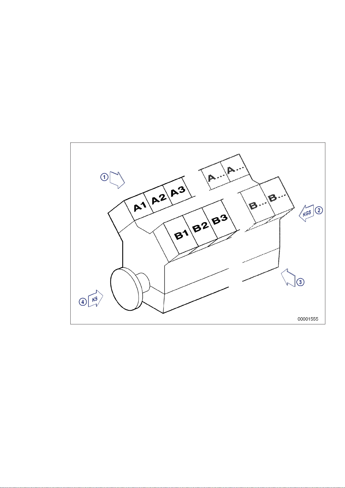
Engine sides are always designated as viewed from the driving end (KS).
The cylinders of the left engine side are designated "A" and those of the right side "B" (as per DIN ISO
1204). The cylinders of each bank are numbered consecutively, starting with No. 1 at the driving end.
Other components are numbered in the same way, i.e. starting with No. 1 on driving end.
TIM-ID: 0000002185 - 010
1 Left engine side
2 KGS = Free end
3 Right engine side
4 KS = Driving end
M015710/04E 2012-09 | General Information | 19
Page 5
2.2 Engine layout
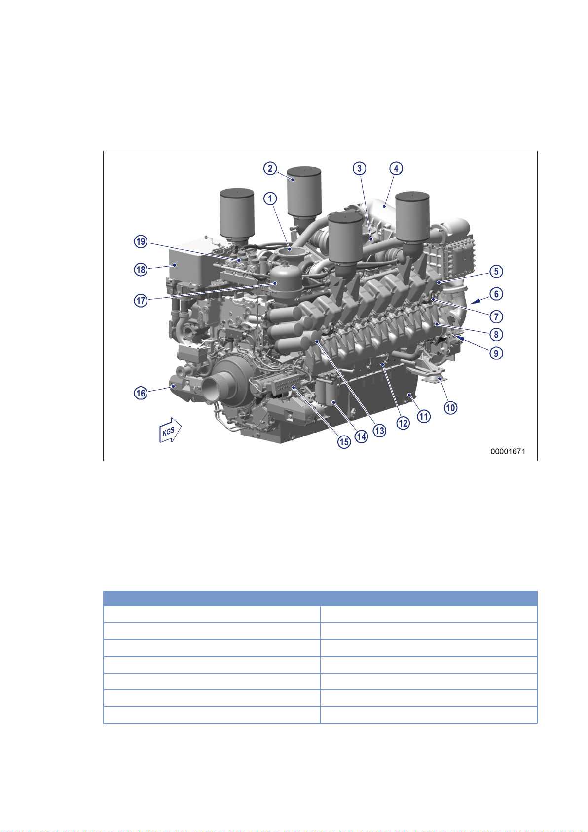
Illustration applies in the same way to 12 V 4000 Gx3.
1 Exhaust gas outlet con‐
nection
2 Air filter
3 Exhaust turbocharger
4 Intercooler
5 Cylinder head
6 Flywheel
7 Lifting eye
8 Charge-air pipe
9 Starter
10 Engine mounting
11 Oil pan
12 Crankcase
13 Engine oil filter
14 Fuel filter
15 HP fuel pump
16 Battery-charging gener‐
ator
17 Centrifugal oil filter
18 Oil heat exchanger
19 Crankcase breather
Engine model designation
Key to the engine model designations 12/16V 4000 Gx3(L)
12/16 Number of cylinders
V Cylinder arrangement: V engine
4000 Series
G Application
x Application segment (2, 4, 6, 8)
3 Design index
L L (enhanced power / speed)
TIM-ID: 0000022697 - 002
20 | General Information | M015710/04E 2012-09
Page 6
2.3 Sensors, actuators and injectors – Overview
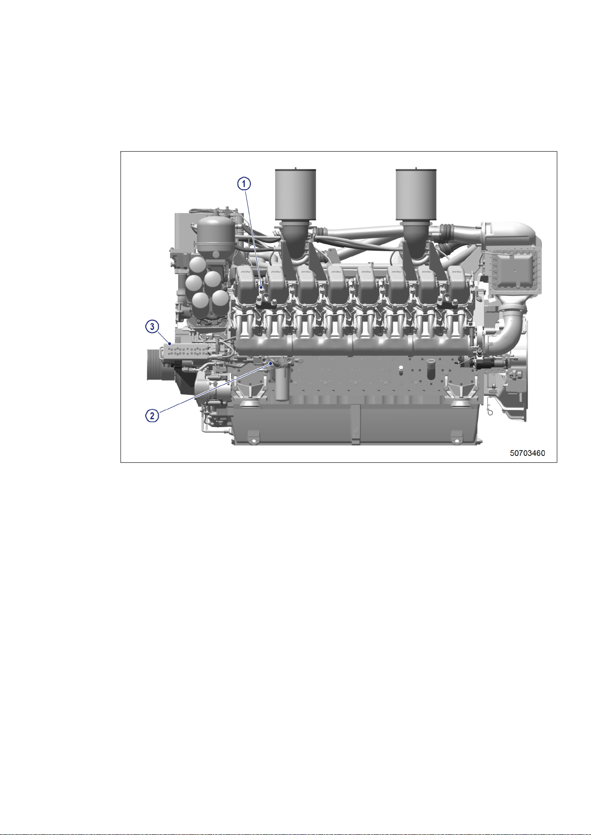
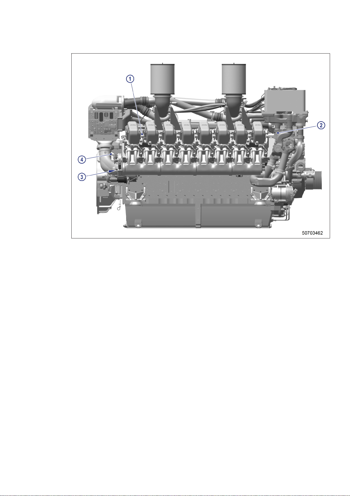
Illustrations are also valid for 12 V 4000 Gx3 engines.
TIM-ID: 0000000954 - 003
1 Temperature sensors
for cylinder exhaust gas
B4.1 to B4.8 (engine
side A)
The injectors (Y39.1 to Y39.8, engine side A) are underneath the cylinder head covers of the cylinder.
Injector replacement and necessary activities (→ Page 146).
2 Sensor B34 (fuel pres‐
sure after filter)
3 M8 (HP fuel pump ac‐
tuator)
M015710/04E 2012-09 | General Information | 21
Page 7
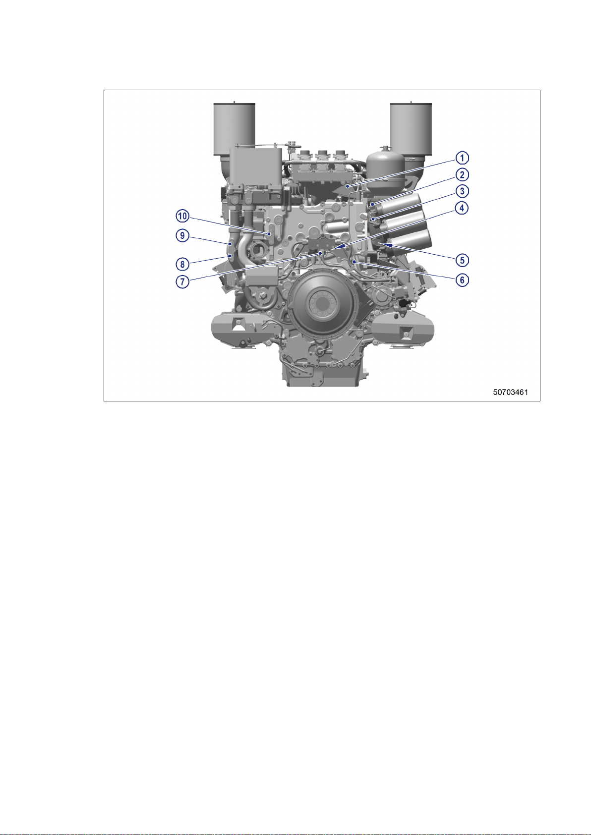
1 B50 (crankcase pres‐
sure)
2 B05.3 (lube oil pressure
before filter)
3 B05 (lube oil pressure
after filter)
4 B33 (fuel temperature in
common rail)
5 B07 (lube oil tempera‐
ture)
6 B01 (camshaft speed)
7 B48 (fuel pressure in
common rail)
8 B43 (charge-air coolant
pressure)
9 B26 (charge-air coolant
temperature)
10 B06 (engine coolant
temperature)
22 | General Information | M015710/04E 2012-09
TIM-ID: 0000000954 - 003
Page 8
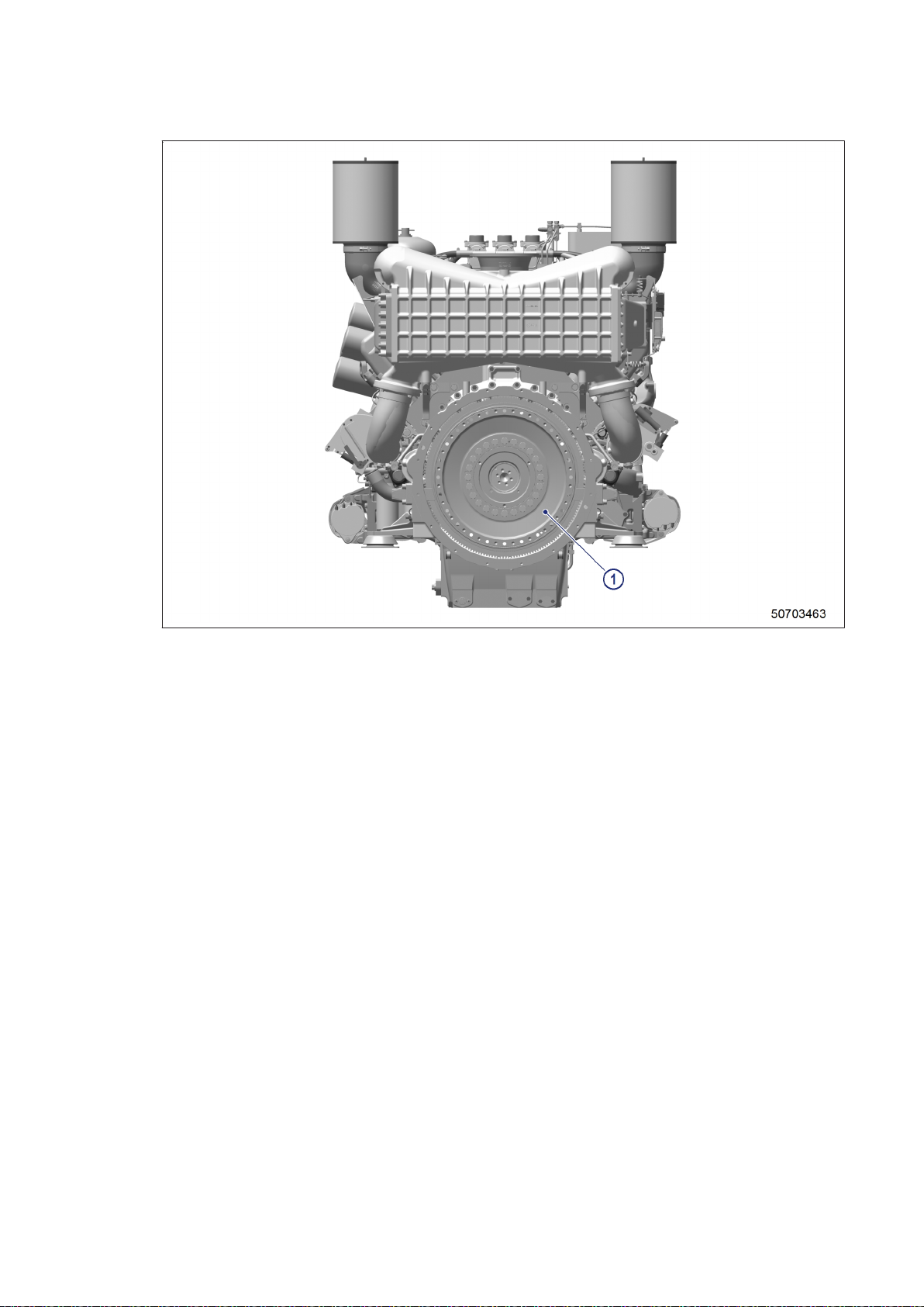
1 Temperature sensors
for cylinder exhaust gas
B4.11 to B4.18 (engine
side B)
3 B10 (charge-air pres‐
sure)
4 B09 (charge-air temper‐
ature)
2 B16 (coolant pressure)
The injectors (Y39.11 to Y39.18, engine side B) are underneath the cylinder head covers of the cylinder.
Injector replacement and required procedure (→ Page 146)
TIM-ID: 0000000954 - 003
M015710/04E 2012-09 | General Information | 23
Page 9
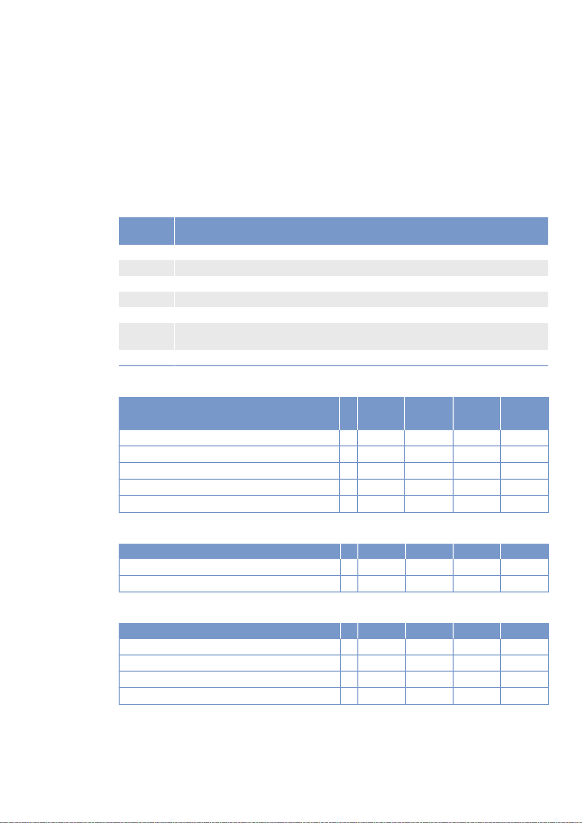
1 B13 (crankshaft speed)
24 | General Information | M015710/04E 2012-09
TIM-ID: 0000000954 - 003
Page 10
3 Technical Data
3.1 16 V 4000 Gx3 engine data: Continuous operation 3A,
optimized fuel consumption
Explanation
Abbrevia‐
tion
DL Ref. value: Continuous power
BL Ref. value: Fuel stop power
A Design value
G Guaranteed value
R Guideline value
L Limit value, up to which the engine can be operated, without change (e.g. of power set‐
N Not yet defined value
Meaning
tings).
Reference conditions
Engine model 16V
4000G43
Application group 3A 3A 3A
Intake air temperature °C 25 25 25
Charge-air coolant temperature °C 55 55 55
Barometric pressure mbar 1000 1000 1000
Site altitude above sea level m 100 100 100
16V
4000G63
16V
4000G83
TIM-ID: 0000022714 - 002
Power-related data (power ratings are net brake power to ISO 3046)
Number of cylinders 16 16 16
Rated engine speed A rpm 1800 1500 1800
Continuous power as per ISO 3046 A kW 1560 1635 1710
General conditions (for maximum power)
Number of cylinders 16 16 16
Intake depression (new filter) A mbar 15 15 15
Intake depression, max. L mbar 50 50 50
Exhaust overpressure A mbar 30 30 30
Exhaust overpressure, max. L mbar 85 85 85
M015710/04E 2012-09 | Technical Data | 25
Page 11
Model related data (basic design)
Number of cylinders 16 16 16
Number of cylinders 16 16 16
Cylinder arrangement: V-angle Degrees
(°)
Bore mm 170 170 170
Stroke mm 210 210 210
Cylinder displacement Liters 4.77 4.77 4.77
Total displacement Liters 76.3 76.3 76.3
Compression ratio 16.5 16.5 16.5
Inlet valves per cylinder 2 2 2
Exhaust valves per cylinder 2 2 2
90 90 90
Combustion air / Exhaust gas
Number of cylinders 16 16 16
Charge-air pressure before cylinder - BL R bar abs 2.7 2.6 2.9
Coolant system (HT circuit)
Number of cylinders 16 16 16
Coolant temperature (at engine connection: outlet to
cooling equipment)
Coolant temperature after engine, warning R °C 102 102 102
Coolant temperature after engine, shutdown L °C 104 104 104
Coolant antifreeze content, max. L % 50 50 50
Pressure loss in off-engine cooling system, max. L bar 0.7 0.7 0.7
A °C 100 100 100
Coolant system (LT circuit)
Number of cylinders 16 16 16
Coolant temperature before intercooler (at engine
connection: from cooling equipment)
Coolant antifreeze content, max. L % 50 50 50
Pressure loss in off-engine cooling system, max. L bar 0.7 0.7 0.7
A °C 55 55 55
Lube oil system
Number of cylinders 16 16 16
Lube-oil operating temperature before engine, from R °C 90 89 88
Lube-oil operating temperature before engine, to R °C 96 95 95
Lube-oil temperature before engine, warning R °C 97 97 97
Lube-oil temperature before engine, shutdown L °C 99 99 99
Lube-oil operating pressure before engine, from R bar 4.7 4.2 4.7
Lube-oil operating pressure before engine, to R bar 6.5 5.5 6.5
TIM-ID: 0000022714 - 002
26 | Technical Data | M015710/04E 2012-09
Page 12
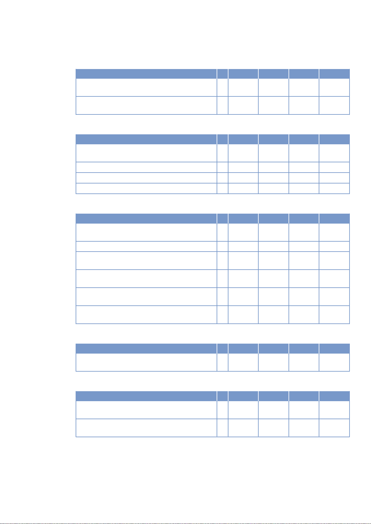
Fuel system
Number of cylinders 16 16 16
Fuel pressure at engine inlet connection, min. (when
engine is starting)
Fuel pressure at engine inlet connection, max.
(when engine is starting)
L bar -0.1 -0.1 -0.1
L bar 1.5 1.5 1.5
General operating data
Number of cylinders 16 16 16
Cold start capability: air temperature (w/o start aid,
w/o preheating) - (case A)
Coolant preheating: preheating temperature (min.) R °C 32 32 32
Firing speed, from R rpm 80 80 80
Firing speed, to R rpm 120 120 120
R °C 10 10 10
Capacities
Number of cylinders 16 16 16
Engine coolant capacity, engine side (without cool‐
ing equipment)
Charge-air coolant, engine side R Liters 50 50 50
Engine oil, total, for initial filling (standard oil system)
(option: max. operating inclinations)
Oil change quantity, max. (standard oil system) (op‐
tion: max. operating inclinations)
Oil pan capacity at dipstick mark “min.” (standard oil
system) (option: max. operating inclinations)
Oil pan capacity at dipstick mark “max.” (standard oil
system) (option: max. operating inclinations)
R Liters 175 175 175
R Liters 300 300 300
R Liters 240 240 240
L Liters 210 210 210
L Liters 240 240 240
TIM-ID: 0000022714 - 002
Weights / main dimensions
Number of cylinders 16 16 16
Engine dry weight (basic engine configuration ac‐
cording to scope of delivery specifications)
R kg 7700 7700 7700
Acoustics
Number of cylinders 16 16 16
Exhaust noise, unsilenced - BL (sound power level
LW, ISO 6798)
Engine surface noise with attenuated intake noise
(filter) - BL (sound power level LW, ISO 6798)
R dB(A) 126 124 127
R dB(A) 124 124 124
M015710/04E 2012-09 | Technical Data | 27
Page 13
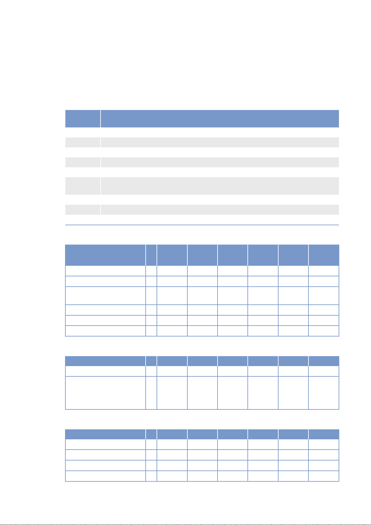
3.2 12 V 4000 Gx3 engine data: Continuous operation, variable
3B, optimized fuel consumption
Explanation
Abbrevia‐
tion
DL Ref. value: Continuous power
BL Ref. value: Fuel stop power
A Design value
G Guaranteed value
R Guideline value
L Limit value, up to which the engine can be operated, without change (e.g. of power set‐
N Not yet defined value
- Not applicable
X Applicable
Meaning
tings).
Reference conditions
Engine model 12V4000
Application group 3B 3B 3B 3B 3B
Intake air temperature °C 25 25 25 25 25
Charge-air coolant tempera‐
ture
Raw water inlet temperature °C - - - - -
Barometric pressure mbar 1000 1000 1000 1000 1000
Site altitude above sea level m 100 100 100 100 100
°C 55 55 55 55 55
G23
12V4000
G23R
12V4000
G43
12V4000
G63
12V4000
G83
Power-related data (power ratings are net brake power to ISO 3046)
Number of cylinders 12 12 12 12 12
Rated engine speed A rpm 1500 1500 1800 1500 1800
Continuous power ISO 3046
(10% overload capability, de‐
sign power DIN 6280, ISO
8528)
General conditions (for maximum power)
Number of cylinders 12 12 12 12 12
Intake depression (new filter) A mbar 15 15 15 15 15
Intake depression, max. L mbar 50 50 50 50 50
Exhaust overpressure A mbar 30 30 30 30 30
Exhaust overpressure, max. L mbar 85 85 85 85 85
28 | Technical Data | M015710/04E 2012-09
A kW 1420 1205 1520 1575 1736
TIM-ID: 0000002981 - 002
Page 14
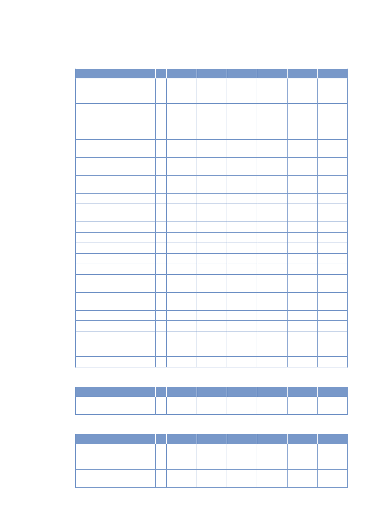
Model related data (basic design)
Number of cylinders 12 12 12 12 12
Engine with exhaust turbo‐
charging (ETC) and chargeair cooling (CAC)
Uncooled exhaust lines X X X X X
Operating method: Fourstroke cycle, diesel, singleaction
Combustion method: direct
fuel injection
Cooling method: Treated wa‐
ter
Direction of rotation: c.c.w.
(facing driving end)
Number of cylinders 12 12 12 12 12
Cylinder arrangement: V-an‐
gle
Degrees
(°)
Bore mm 170 170 170 170 170
Stroke mm 210 210 210 210 210
Cylinder displacement Liters 4.77 4.77 4.77 4.77 4.77
Total displacement Liters 57.2 57.2 57.2 57.2 57.2
Compression ratio 16.5 16.5 16.5 16.5 16.5
Cylinder heads: individual
cylinder heads
Cylinder liners: wet, replace‐
able
Inlet valves per cylinder 2 2 2 2 2
Exhaust valves per cylinder 2 2 2 2 2
Standard housing connect‐
SAE 00 00 00 00 00
ing flange (engine main
PTO)
Flywheel interface DISC 21 21 21 21 21
X X X X X
X X X X X
X X X X X
X X X X X
X X X X X
90 90 90 90 90
X X X X X
X X X X X
TIM-ID: 0000002981 - 002
Combustion air / Exhaust gas
Number of cylinders 12 12 12 12 12
Charge air pressure before
R bar abs 2.6 2.4 2.9 2.9 3.2
cylinder - DL
Coolant system (HT circuit)
Number of cylinders 12 12 12 12 12
Coolant temperature (at en‐
gine connection: outlet to
cooling equipment)
Coolant temperature after
engine, warning
A °C 100 100 100 100 100
R °C 102 102 102 102 102
M015710/04E 2012-09 | Technical Data | 29
Page 15
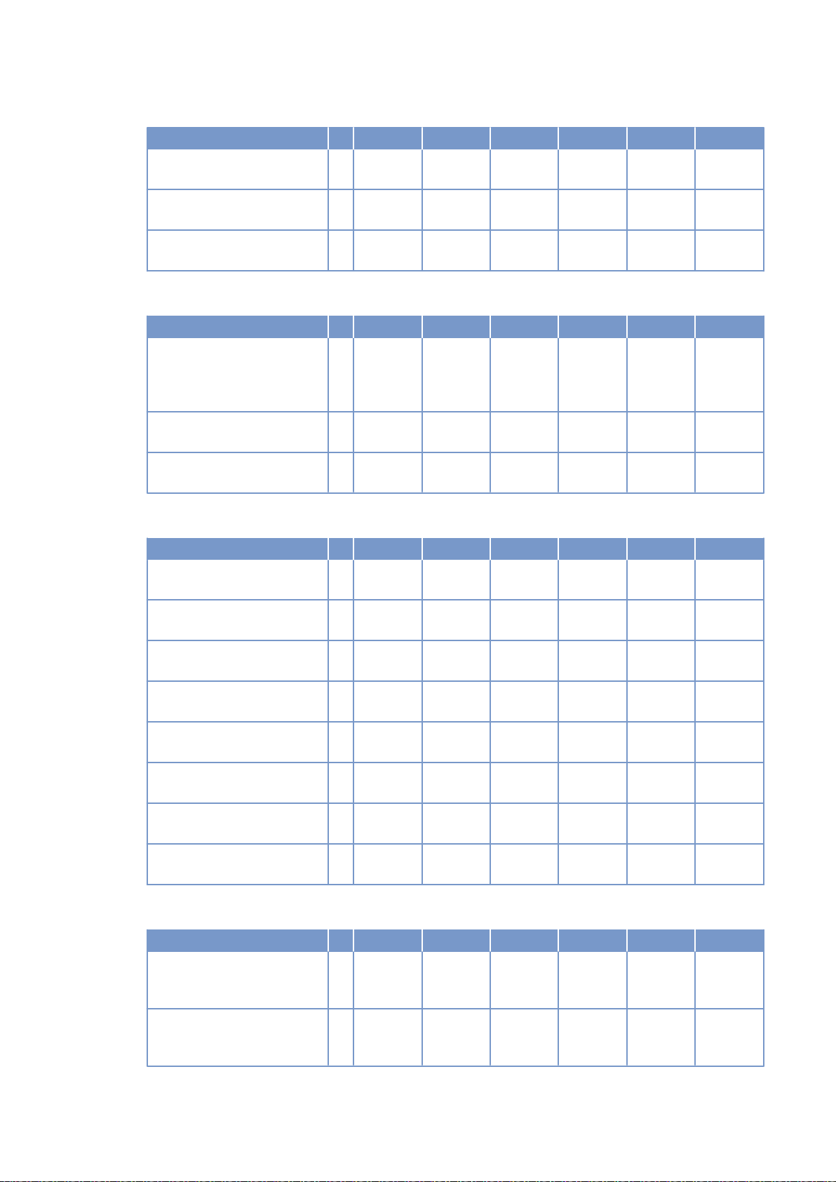
Number of cylinders 12 12 12 12 12
Coolant temperature after
L °C 104 104 104 104 104
engine, shutdown
Coolant antifreeze content,
L % 50 50 50 50 50
max.
Pressure loss in off-engine
L bar 0.7 0.7 0.7 0.7 0.7
cooling system, max.
Coolant system (LT circuit)
Number of cylinders 12 12 12 12 12
Coolant temperature before
A °C 55 55 55 55 55
intercooler (at engine con‐
nection: from cooling equip‐
ment)
Coolant antifreeze content,
L % 50 50 50 50 50
max.
Pressure loss in off-engine
L bar 0.7 0.7 0.7 0.7 0.7
cooling system, max.
Lube oil system
Number of cylinders 12 12 12 12 12
Lube-oil operating tempera‐
R °C 88 88 88 88 88
ture before engine, from
Lube-oil operating tempera‐
R °C 98 98 98 98 98
ture before engine, to
Lube-oil temperature before
R °C 99 99 99 99 99
engine, warning
Lube-oil temperature before
L °C 101 101 101 101 101
engine, shutdown
Lube-oil operating pressure
R bar 5.0 5.0 5.0 5.0 5.0
before engine, from
Lube-oil operating pressure
R bar 6.0 7.0 7.0 7.0 7.0
before engine, to
Lube-oil operating pressure
R bar -- -- -- -- -before engine, warning
Lube-oil operating pressure
L bar -- -- -- -- -before engine, shutdown
Fuel system
Number of cylinders 12 12 12 12 12
Fuel pressure at engine inlet
connection, min. (when en‐
gine is starting)
Fuel pressure at engine inlet
connection, max. (when en‐
gine is starting)
L bar -0.1 -0.1 -0.1 -0.1 -0.1
L bar 1.5 1.5 1.5 1.5 1.5
TIM-ID: 0000002981 - 002
30 | Technical Data | M015710/04E 2012-09
Page 16
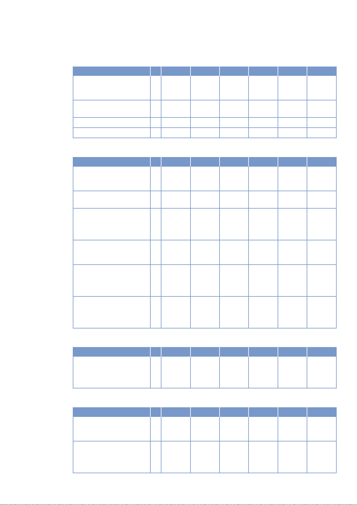
General operating data
Number of cylinders 12 12 12 12 12
Cold start capability: air tem‐
perature (w/o start aid, w/o
preheating) - (case A)
Coolant preheating: preheat‐
ing temperature (min.)
Firing speed, from R rpm 80 80 80 80 80
Firing speed, to R rpm 120 120 120 120 120
R °C 10 10 10 10 10
R °C 32 32 32 32 32
Capacities
Number of cylinders 12 12 12 12 12
Engine coolant capacity, en‐
gine side (without cooling
equipment)
Charge-air coolant, engine
side
Engine oil, total, for initial fill‐
ing (standard oil system)
(option: max. operating incli‐
nations)
Oil change quantity, max.
(standard oil system) (option:
max. operating inclinations)
Oil pan capacity at dipstick
mark “min.” (standard oil
system) (option: max. oper‐
ating inclinations)
Oil pan capacity at dipstick
mark “max.” (standard oil
system) (option: max. oper‐
ating inclinations)
R Liters 160 160 160 160 160
R Liters 40 40 40 40 40
R Liters 260 260 260 260 260
R Liters 260 260 260 260 260
L Liters 160 160 160 160 160
L Liters 200 200 200 200 200
TIM-ID: 0000002981 - 002
Weights / main dimensions
Number of cylinders 12 12 12 12 12
Engine dry weight (basic en‐
gine configuration according
to scope of delivery specifi‐
cations)
R kg 6200* 6200* 6200* 6200* 6200*
Acoustics
Number of cylinders 12 12 12 12 12
Exhaust noise, unsilenced DL (sound power level LW,
ISO 6798)
Engine surface noise with at‐
tenuated intake noise filter) DL (sound power level LW,
ISO 6798)
R dB(A) 124 124 125 125 127
R dB(A) 120 120 122 121 123
M015710/04E 2012-09 | Technical Data | 31
Page 17
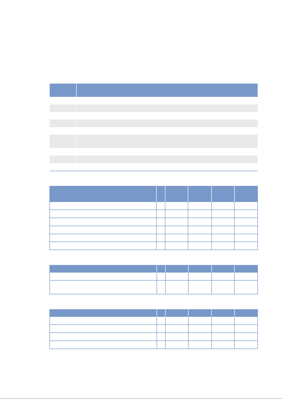
3.3 12 V 4000 Gx3 engine data: Continuous operation, variable
3B, optimized exhaust emissions (TA-Luft)
Explanation
Abbrevia‐
tion
DL Ref. value: Continuous power
BL Ref. value: Fuel stop power
A Design value
G Guaranteed value
R Guideline value
L Limit value, up to which the engine can be operated, without change (e.g. of power set‐
N Not yet defined value
- Not applicable
X Applicable
Meaning
tings).
Reference conditions
Engine model 12V4000
Application group 3B 3B 3B
Intake air temperature °C 25 25 25
Charge-air coolant temperature °C 55 55 55
Raw water inlet temperature °C - - -
Barometric pressure mbar 1000 1000 1000
Site altitude above sea level m 100 100 100
G23
12V4000
G23R
12V4000
G63
Power-related data (power ratings are net brake power to ISO 3046)
Number of cylinders 12 12 12
Rated engine speed A rpm 1500 1500 1500
Continuous power ISO 3046 (10% overload capabil‐
ity, design power DIN 6280, ISO 8528)
General conditions (for maximum power)
Number of cylinders 12 12 12
Intake depression (new filter) A mbar 15 15 15
Intake depression, max. L mbar 50 50 50
Exhaust overpressure A mbar 30 30 30
Exhaust overpressure, max. L mbar 85 85 85
32 | Technical Data | M015710/04E 2012-09
A kW 1420 1205 1575
TIM-ID: 0000003032 - 002
Page 18
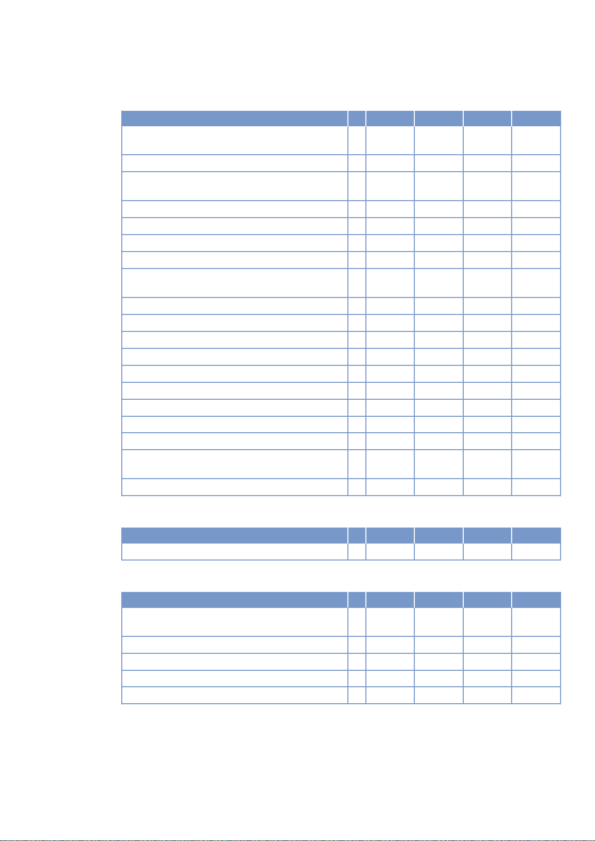
Model related data (basic design)
Number of cylinders 12 12 12
Engine with exhaust turbocharging (ETC) and
charge-air cooling (CAC)
Uncooled exhaust lines X X X
Operating method: Four-stroke cycle, diesel, singleaction
Combustion method: direct fuel injection X X X
Cooling method: Treated water X X X
Direction of rotation: c.c.w. (facing driving end) X X X
Number of cylinders 12 12 12
Cylinder arrangement: V-angle Degrees
(°)
Bore mm 170 170 170
Stroke mm 210 210 210
Cylinder displacement Liters 4.77 4.77 4.77
Total displacement Liters 57.2 57.2 57.2
Compression ratio 16.5 16.5 16.5
Cylinder heads: individual cylinder heads X X X
Cylinder liners: wet, replaceable X X X
Inlet valves per cylinder 2 2 2
Exhaust valves per cylinder 2 2 2
Standard housing connecting flange (engine main
SAE 00 00 00
PTO)
Flywheel interface DISC 21 21 21
X X X
X X X
90 90 90
TIM-ID: 0000003032 - 002
Combustion air / Exhaust gas
Number of cylinders 12 12 12
Charge air pressure before cylinder - DL R bar abs 3.2 2.9 3.5
Coolant system (HT circuit)
Number of cylinders 12 12 12
Coolant temperature (at engine connection: outlet to
cooling equipment)
Coolant temperature after engine, warning R °C 102 102 102
Coolant temperature after engine, shutdown L °C 104 104 104
Coolant antifreeze content, max. L % 50 50 50
Pressure loss in off-engine cooling system, max. L bar 0.7 0.7 0.7
A °C 100 100 100
M015710/04E 2012-09 | Technical Data | 33
Page 19
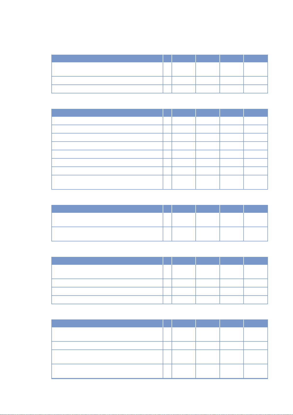
Coolant system (LT circuit)
Number of cylinders 12 12 12
Coolant temperature before intercooler (at engine
connection: from cooling equipment)
Coolant antifreeze content, max. L % 50 50 50
Pressure loss in off-engine cooling system, max. L bar 0.7 0.7 0.7
A °C 55 55 55
Lube oil system
Number of cylinders 12 12 12
Lube-oil operating temperature before engine, from R °C 88 88 88
Lube-oil operating temperature before engine, to R °C 98 98 98
Lube-oil temperature before engine, warning R °C 99 99 99
Lube-oil temperature before engine, shutdown L °C 101 101 101
Lube-oil operating pressure before engine, from R bar 5.0 5.0 5.0
Lube-oil operating pressure before engine, to R bar 7.0 7.0 7.0
Lube-oil operating pressure before engine, warning R bar -- -- --
Lube-oil operating pressure before engine, shut‐
down
L bar -- -- --
Fuel system
Number of cylinders 12 12 12
Fuel pressure at engine inlet connection, min. (when
engine is starting)
Fuel pressure at engine inlet connection, max.
(when engine is starting)
L bar -0.1 -0.1 -0.1
L bar 1.5 1.5 1.5
General operating data
Number of cylinders 12 12 12
Cold start capability: air temperature (w/o start aid,
w/o preheating) - (case A)
Coolant preheating: preheating temperature (min.) R °C 32 32 32
Firing speed, from R rpm 80 80 80
Firing speed, to R rpm 120 120 120
R °C 10 10 10
Capacities
Number of cylinders 12 12 12
Engine coolant capacity, engine side (without cool‐
ing equipment)
Charge-air coolant, engine side R Liters 40 40 40
Engine oil, total, for initial filling (standard oil system)
(option: max. operating inclinations)
Oil change quantity, max. (standard oil system) (op‐
tion: max. operating inclinations)
R Liters 160 160 160
R Liters 260 260 260
R Liters 260 260 260
TIM-ID: 0000003032 - 002
34 | Technical Data | M015710/04E 2012-09
Page 20
Number of cylinders 12 12 12
Oil pan capacity at dipstick mark “min.” (standard oil
L Liters 160 160 160
system) (option: max. operating inclinations)
Oil pan capacity at dipstick mark “max.” (standard oil
L Liters 200 200 200
system) (option: max. operating inclinations)
Weights / main dimensions
Number of cylinders 12 12 12
Engine dry weight (basic engine configuration ac‐
R kg 6200* 6200* 6200*
cording to scope of delivery specifications)
Acoustics
Number of cylinders 12 12 12
Exhaust noise, unsilenced - DL (sound power level
LW, ISO 6798)
Engine surface noise with attenuated intake noise
filter) - DL (sound power level LW, ISO 6798)
R dB(A) 126 126 127
R dB(A) 122 122 122
TIM-ID: 0000003032 - 002
M015710/04E 2012-09 | Technical Data | 35
Page 21
3.4 16 V 4000 Gx3 engine data: Continuous operation, variable
3B, optimized fuel consumption
Explanation
Abbrevia‐
tion
DL Ref. value: Continuous power
BL Ref. value: Fuel stop power
A Design value
G Guaranteed value
R Guideline value
L Limit value, up to which the engine can be operated, without change (e.g. of power set‐
N Not yet defined value
- Not applicable
X Applicable
Meaning
tings).
Reference conditions
Engine model 16V
4000G23
Application group 3B 3B 3B 3B
Intake air temperature °C 25 25 25 25
Charge-air coolant temperature °C 55 55 55 55
Raw-water inlet temperature °C - - - -
Barometric pressure mbar 1000 1000 1000 1000
Site altitude above sea level m 100 100 100 100
16V
4000G43
16V
4000G63
16V
4000G83
Power-related data (power ratings are net brake power to ISO 3046)
Number of cylinders 16 16 16 16
Rated engine speed A rpm 1500 1800 1500 1800
Continuous power ISO 3046 (10% over‐
load capability, design power DIN 6280,
ISO 8528)
General conditions (for maximum power)
Number of cylinders 16 16 16 16
Intake depression (new filter) A mbar 15 15 15 15
Intake depression, max. L mbar 50 50 50 50
Exhaust overpressure A mbar 30 30 30 30
Exhaust overpressure, max. L mbar 85 85 85 85
36 | Technical Data | M015710/04E 2012-09
A kW 1798 2020 1965 2280
TIM-ID: 0000003003 - 002
Page 22
Model related data (basic design)
Number of cylinders 16 16 16 16
Engine with exhaust turbocharging
(ETC) and charge-air cooling (CAC)
Uncooled exhaust lines X X X X
Operating method: Four-stroke cycle,
diesel, single-action
Combustion method: direct fuel injection X X X X
Cooling method: Treated water X X X X
Direction of rotation: c.c.w. (facing driv‐
ing end)
Number of cylinders 16 16 16 16
Cylinder arrangement: V-angle Degrees 90 90 90 90
Bore mm 170 170 170 170
Stroke mm 210 210 210 210
Cylinder displacement Liters 4.77 4.77 4.77 4.77
Total displacement Liters 76.3 76.3 76.3 76.3
Compression ratio 16.5 16.5 16.5 16.5
Cylinder heads: individual cylinder
heads
Cylinder liners: wet, replaceable X X X X
Inlet valves per cylinder 2 2 2 2
Exhaust valves per cylinder 2 2 2 2
Standard housing connecting flange (en‐
SAE 00 00 00 00
gine main PTO)
Flywheel interface DISC 21 21 21 21
X X X X
X X X X
X X X X
X X X X
TIM-ID: 0000003003 - 002
Combustion air / Exhaust gas
Number of cylinders 16 16 16 16
Charge air pressure before cylinder - DL R bar abs 2.6 2.9 2.8 3.1
Coolant system (HT circuit)
Number of cylinders 16 16 16 16
Coolant temperature (at engine connec‐
tion: outlet to cooling equipment)
Coolant temperature after engine, warn‐
ing
Coolant temperature after engine, shut‐
down
Coolant antifreeze content, max. L % 50 50 50 50
Pressure loss in off-engine cooling sys‐
tem, max.
A °C 100 100 100 100
R °C 102 102 102 102
L °C 104 104 104 104
L bar 0.7 0.7 0.7 0.7
M015710/04E 2012-09 | Technical Data | 37
Page 23
Coolant system (LT circuit)
Number of cylinders 16 16 16 16
Coolant temperature before intercooler
(at engine connection: from cooling
equipment)
Coolant antifreeze content, max. L % 50 50 50 50
Pressure loss in off-engine cooling sys‐
tem, max.
A °C 55 55 55 55
L bar 0.7 0.7 0.7 0.7
Lube oil system
Number of cylinders 16 16 16 16
Lube-oil operating temperature before
engine, from
Lube-oil operating temperature before
engine, to
Lube-oil temperature before engine,
warning
Lube-oil temperature before engine,
shutdown
Lube-oil operating pressure before en‐
gine, from
Lube-oil operating pressure before en‐
gine, to
Lube-oil operating pressure before en‐
gine, warning
Lube-oil operating pressure before en‐
gine, shutdown
R °C 89 90 89 88
R °C 95 96 95 95
R °C 97 97 97 97
L °C 99 99 99 99
R bar 4.2 4.7 4.2 4.7
R bar 5.5 6.5 5.5 6.5
R bar -- -- -- --
L bar -- -- -- --
Fuel system
Number of cylinders 16 16 16 16
Fuel pressure at engine inlet connection,
min. (when engine is starting)
Fuel pressure at engine inlet connection,
max. (when engine is starting)
L bar -0.1 -0.1 -0.1 -0.1
L bar 1.5 1.5 1.5 1.5
General operating data
Number of cylinders 16 16 16 16
Cold start capability: air temperature (w/
o start aid, w/o preheating) - (case A)
Coolant preheating: preheating tempera‐
ture (min.)
Firing speed, from R rpm 80 80 80 80
Firing speed, to R rpm 120 120 120 120
R °C 10 10 10 10
R °C 32 32 32 32
TIM-ID: 0000003003 - 002
38 | Technical Data | M015710/04E 2012-09
Page 24
Capacities
Number of cylinders 16 16 16 16
Engine coolant capacity, engine side
R Liters 260 260 260 260
(without cooling equipment)
Charge-air coolant, engine side R Liters 50 50 50 50
Engine oil, total, for initial filling (stand‐
R Liters 300 300 300 300
ard oil system) (option: max. operating
inclinations)
Oil change quantity, max. (standard oil
R Liters 240 240 240 240
system) (option: max. operating inclina‐
tions)
Oil pan capacity at dipstick mark “min.”
L Liters 210 210 210 210
(standard oil system) (option: max. oper‐
ating inclinations)
Oil pan capacity at dipstick mark “max.”
L Liters 240 240 240 240
(standard oil system) (option: max. oper‐
ating inclinations)
Weights / main dimensions
Number of cylinders 16 16 16 16
Engine dry weight (basic engine configu‐
ration according to scope of delivery
specifications)
R kg 7700 7700 7700 7700
TIM-ID: 0000003003 - 002
Acoustics
Number of cylinders 16 16 16 16
Exhaust noise, unsilenced - DL (sound
power level LW, ISO 6798)
Engine surface noise with attenuated in‐
take noise filter) - DL (sound power level
LW, ISO 6798)
R dB(A) 125 127 126 129
R dB(A) 126 125 128 125
M015710/04E 2012-09 | Technical Data | 39
Page 25
3.5 12/16 V 4000 Gx3 engine data: Continuous operation,
variable 3B, optimized exhaust emissions (EPA stage 2)
Explanation
Abbrevia‐
tion
DL Ref. value: Continuous power
BL Ref. value: Fuel stop power
A Design value
G Guaranteed value
R Guideline value
L Limit value, up to which the engine can be operated, without change (e.g. of power set‐
N Not yet defined value
- Not applicable
X Applicable
Meaning
tings).
Reference conditions
Engine model 12V
4000G43
Application group 3B 3B 3B 3B
Intake air temperature °C 25 25 25 25
Charge-air coolant temperature °C 45 45 45 45
Raw-water inlet temperature °C - - - -
Barometric pressure mbar 1000 1000 1000 1000
Site altitude above sea level m 100 100 100 100
12V
4000G83
16V
4000G43
16V
4000G83
Power-related data (power ratings are net brake power to ISO 3046)
Number of cylinders 12 12 16 16
Rated engine speed A rpm 1800 1800 1800 1800
Continuous power ISO 3046 (10% over‐
load capability, design power DIN 6280,
ISO 8528)
General conditions (for maximum power)
Number of cylinders 12 12 16 16
Intake depression (new filter) A mbar 15 15 15 15
Intake depression, max. L mbar 50 50 50 50
Exhaust overpressure A mbar 30 30 30 30
Exhaust overpressure, max. L mbar 85 85 85 85
40 | Technical Data | M015710/04E 2012-09
A kW 1520 1736 2020 2280
TIM-ID: 0000003018 - 002
Page 26
Model related data (basic design)
Number of cylinders 12 12 16 16
Engine with exhaust turbocharging
(ETC) and charge-air cooling (CAC)
Uncooled exhaust lines X X X X
Operating method: Four-stroke cycle,
diesel, single-action
Combustion method: direct fuel injection X X X X
Cooling method: Treated water X X X X
Direction of rotation: c.c.w. (facing driv‐
ing end)
Number of cylinders 12 12 16 16
Cylinder arrangement: V-angle Degrees 90 90 90 90
Bore mm 170 170 170 170
Stroke mm 210 210 210 210
Cylinder displacement Liters 4.77 4.77 4.77 4.77
Total displacement Liters 57.2 57.2 76.3 76.3
Compression ratio 16.5 16.5 16.5 16.5
Cylinder heads: individual cylinder
heads
Cylinder liners: wet, replaceable X X X X
Inlet valves per cylinder 2 2 2 2
Exhaust valves per cylinder 2 2 2 2
Standard housing connecting flange (en‐
SAE 00 00 00 00
gine main PTO)
Flywheel interface DISC 21 21 21 21
X X X X
X X X X
X X X X
X X X X
TIM-ID: 0000003018 - 002
Combustion air / Exhaust gas
Number of cylinders 12 12 16 16
Charge air pressure before cylinder - DL R bar abs 3.0 3.1 3.0 3.2
Coolant system (HT circuit)
Number of cylinders 12 12 16 16
Coolant temperature (at engine connec‐
tion: outlet to cooling equipment)
Coolant temperature after engine, warn‐
ing
Coolant temperature after engine, shut‐
down
Coolant antifreeze content, max. L % 50 50 50 50
Pressure loss in off-engine cooling sys‐
tem, max.
A °C 100 100 100 100
R °C 102 102 102 102
L °C 104 104 104 104
L bar 0.7 0.7 0.7 0.7
M015710/04E 2012-09 | Technical Data | 41
Page 27
Coolant system (LT circuit)
Number of cylinders 12 12 16 16
Coolant temperature before intercooler
(at engine connection: from cooling
equipment)
Coolant antifreeze content, max. L % 50 50 50 50
Pressure loss in off-engine cooling sys‐
tem, max.
A °C 45 45 45 45
L bar 0.7 0.7 0.7 0.7
Lube oil system
Number of cylinders 12 12 16 16
Lube-oil operating temperature before
engine, from
Lube-oil operating temperature before
engine, to
Lube-oil temperature before engine,
warning
Lube-oil temperature before engine,
shutdown
Lube-oil operating pressure before en‐
gine, from
Lube-oil operating pressure before en‐
gine, to
Lube-oil operating pressure before en‐
gine, warning
Lube-oil operating pressure before en‐
gine, shutdown
R °C 88 88 90 88
R °C 98 98 96 94
R °C 99 99 97 97
L °C 101 101 99 99
R bar 5.0 5.0 4.7 4.7
R bar 7.0 7.0 6.5 6.5
R bar -- -- -- --
L bar -- -- -- --
Fuel system
Number of cylinders 12 12 16 16
Fuel pressure at engine inlet connection,
min. (when engine is starting)
Fuel pressure at engine inlet connection,
max. (when engine is starting)
L bar -0.1 -0.1 -0.1 -0.1
L bar 1.5 1.5 1.5 1.5
General operating data
Number of cylinders 12 12 16 16
Cold start capability: air temperature (w/
o start aid, w/o preheating) - (case A)
Coolant preheating: preheating tempera‐
ture (min.)
Firing speed, from R rpm 80 80 80 80
Firing speed, to R rpm 120 120 120 120
R °C 10 10 10 10
R °C 32 32 32 32
TIM-ID: 0000003018 - 002
42 | Technical Data | M015710/04E 2012-09
Page 28
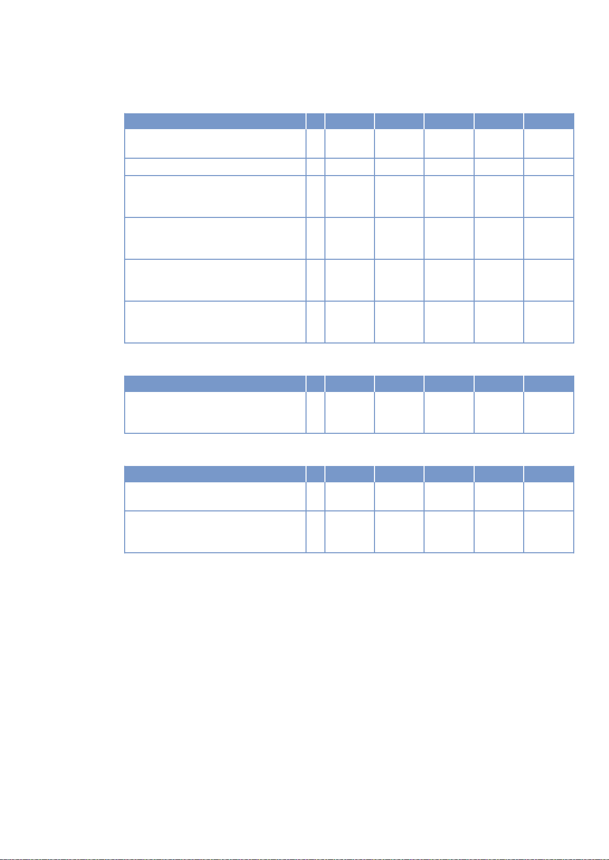
Capacities
Number of cylinders 12 12 16 16
Engine coolant capacity, engine side
R Liters 160 160 260 260
(without cooling equipment)
Charge-air coolant, engine side R Liters 40 40 50 50
Engine oil, total, for initial filling (stand‐
R Liters 260 260 300 300
ard oil system) (option: max. operating
inclinations)
Oil change quantity, max. (standard oil
R Liters 240 240
system) (option: max. operating inclina‐
tions)
Oil pan capacity at dipstick mark “min.”
L Liters 160 160 210 210
(standard oil system) (option: max. oper‐
ating inclinations)
Oil pan capacity at dipstick mark “max.”
L Liters 200 200 240 240
(standard oil system) (option: max. oper‐
ating inclinations)
Weights / main dimensions
Number of cylinders 12 12 16 16
Engine dry weight (basic engine configu‐
ration according to scope of delivery
specifications)
R kg 6200* 6200* 7700 7700
TIM-ID: 0000003018 - 002
Acoustics
Number of cylinders 12 12 16 16
Exhaust noise, unsilenced - DL (sound
power level LW, ISO 6798)
Engine surface noise with attenuated in‐
take noise filter) - DL (sound power level
LW, ISO 6798)
R dB(A) 125 127 127 129
R dB(A) 122 123 125 125
M015710/04E 2012-09 | Technical Data | 43
Page 29
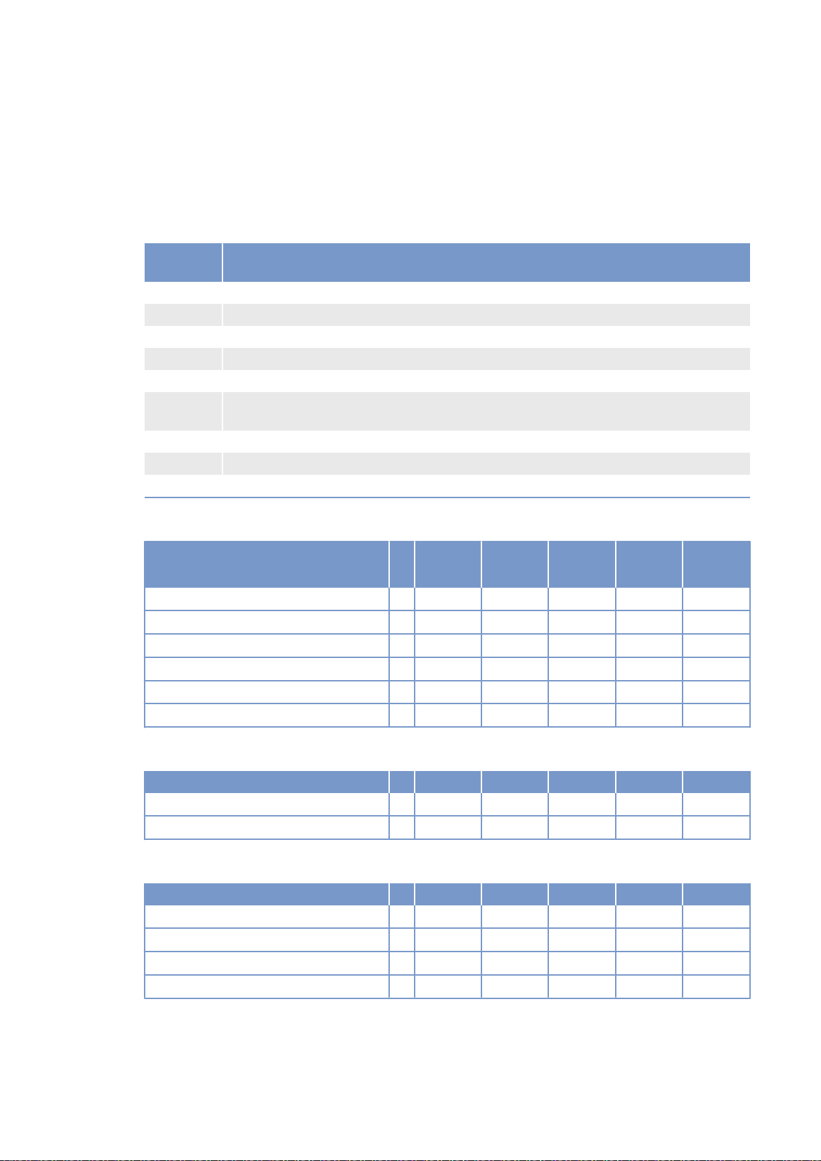
3.6 12V 4000 Gx3 engine data: Standby operation 3D, optimized
fuel consumption
Explanation
Abbrevia‐
tion
DL Ref. value: Continuous power
BL Ref. value: Fuel stop power
A Design value
G Guaranteed value
R Guideline value
L Limit value, up to which the engine can be operated, without change (e.g. of power set‐
N Not yet defined value
- Not applicable
X Applicable
Meaning
tings).
Reference conditions
Engine model 12V
4000G23
Application group 3D 3D 3D 3D
Intake air temperature °C 25 25 25 25
Charge-air coolant temperature °C 55 55 55 55
Raw-water inlet temperature °C - - - -
Barometric pressure mbar 1000 1000 1000 1000
Site altitude above sea level m 100 100 100 100
12V
4000G43
12V
4000G63
12V
4000G83
Power-related data (power ratings are net brake power to ISO 3046)
Number of cylinders 12 12 12 12
Rated engine speed A rpm 1500 1800 1500 1800
Fuel stop power ISO 3046 A kW 1575 1736 1750 1910
General conditions (for maximum power)
Number of cylinders 12 12 12 12
Intake depression (new filter) A mbar 15 15 15 15
Intake depression, max. L mbar 50 50 50 50
Exhaust overpressure A mbar 30 30 30 30
Exhaust overpressure, max. L mbar 85 85 85 85
44 | Technical Data | M015710/04E 2012-09
TIM-ID: 0000002873 - 002
Page 30
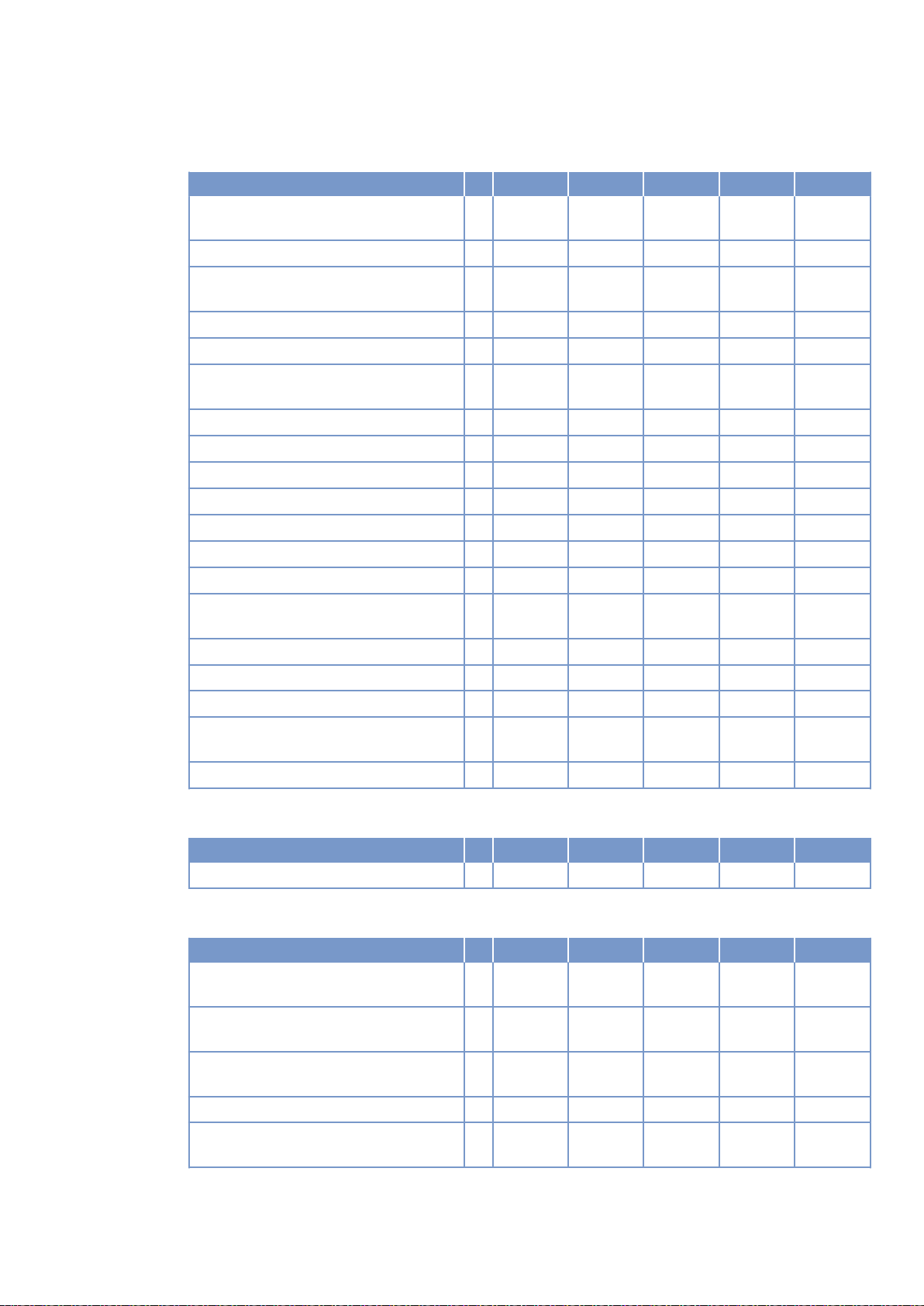
Model related data (basic design)
Number of cylinders 12 12 12 12
Engine with exhaust turbocharging
(ETC) and charge-air cooling (CAC)
Uncooled exhaust lines X X X X
Operating method: Four-stroke cycle,
diesel, single-action
Combustion method: direct fuel injection X X X X
Cooling method: Treated water X X X X
Direction of rotation: c.c.w. (facing driv‐
ing end)
Number of cylinders 12 12 12 12
Cylinder arrangement: V-angle Degrees 90 90 90 90
Bore mm 170 170 170 170
Stroke mm 210 210 210 210
Cylinder displacement Liters 4.77 4.77 4.77 4.77
Total displacement Liters 57.2 57.2 57.2 57.2
Compression ratio 16.5 16.5 16.5 16.5
Cylinder heads: individual cylinder
heads
Cylinder liners: wet, replaceable X X X X
Inlet valves per cylinder 2 2 2 2
Exhaust valves per cylinder 2 2 2 2
Standard housing connecting flange (en‐
SAE 00 00 00 00
gine main PTO)
Flywheel interface DISC 21 21 21 21
X X X X
X X X X
X X X X
X X X X
TIM-ID: 0000002873 - 002
Combustion air / Exhaust gas
Number of cylinders 12 12 12 12
Charge-air pressure before cylinder - BL R bar abs 2.9 3.2 3.2 3.4
Coolant system (HT circuit)
Number of cylinders 12 12 12 12
Coolant temperature (at engine connec‐
tion: outlet to cooling equipment)
Coolant temperature after engine, warn‐
ing
Coolant temperature after engine, shut‐
down
Coolant antifreeze content, max. L % 50 50 50 50
Pressure loss in off-engine cooling sys‐
tem, max.
A °C 100 100 100 100
R °C 102 102 102 102
L °C 104 104 104 104
L bar 0.7 0.7 0.7 0.7
M015710/04E 2012-09 | Technical Data | 45
Page 31
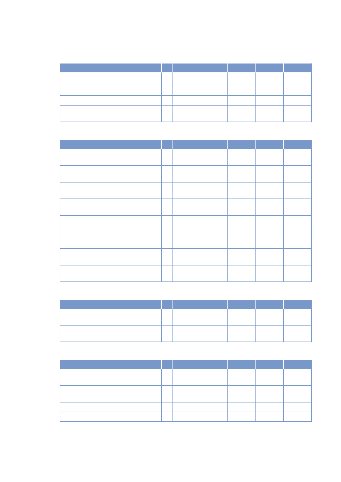
Coolant system (LT circuit)
Number of cylinders 12 12 12 12
Coolant temperature before intercooler
(at engine connection: from cooling
equipment)
Coolant antifreeze content, max. L % 50 50 50 50
Pressure loss in off-engine cooling sys‐
tem, max.
A °C 55 55 55 55
L bar 0.7 0.7 0.7 0.7
Lube oil system
Number of cylinders 12 12 12 12
Lube-oil operating temperature before
engine, from
Lube-oil operating temperature before
engine, to
Lube-oil temperature before engine,
warning
Lube-oil temperature before engine,
shutdown
Lube-oil operating pressure before en‐
gine, from
Lube-oil operating pressure before en‐
gine, to
Lube-oil operating pressure before en‐
gine, warning
Lube-oil operating pressure before en‐
gine, shutdown
R °C 88 88 88 88
R °C 98 98 98 98
R °C 99 99 99 99
L °C 101 101 101 101
R bar 5.0 5.0 5.0 5.0
R bar 7.0 7.0 7.0 7.0
R bar -- -- -- --
L bar -- -- -- --
Fuel system
Number of cylinders 12 12 12 12
Fuel pressure at engine inlet connection,
min. (when engine is starting)
Fuel pressure at engine inlet connection,
max. (when engine is starting)
L bar -0.1 -0.1 -0.1 -0.1
L bar 1.5 1.5 1.5 1.5
General operating data
Number of cylinders 12 12 12 12
Cold start capability: air temperature (w/
o start aid, w/o preheating) - (case A)
Coolant preheating: preheating tempera‐
ture (min.)
Firing speed, from R rpm 80 80 80 80
Firing speed, to R rpm 120 120 120 120
R °C 10 10 10 10
R °C 32 32 32 32
TIM-ID: 0000002873 - 002
46 | Technical Data | M015710/04E 2012-09
Page 32
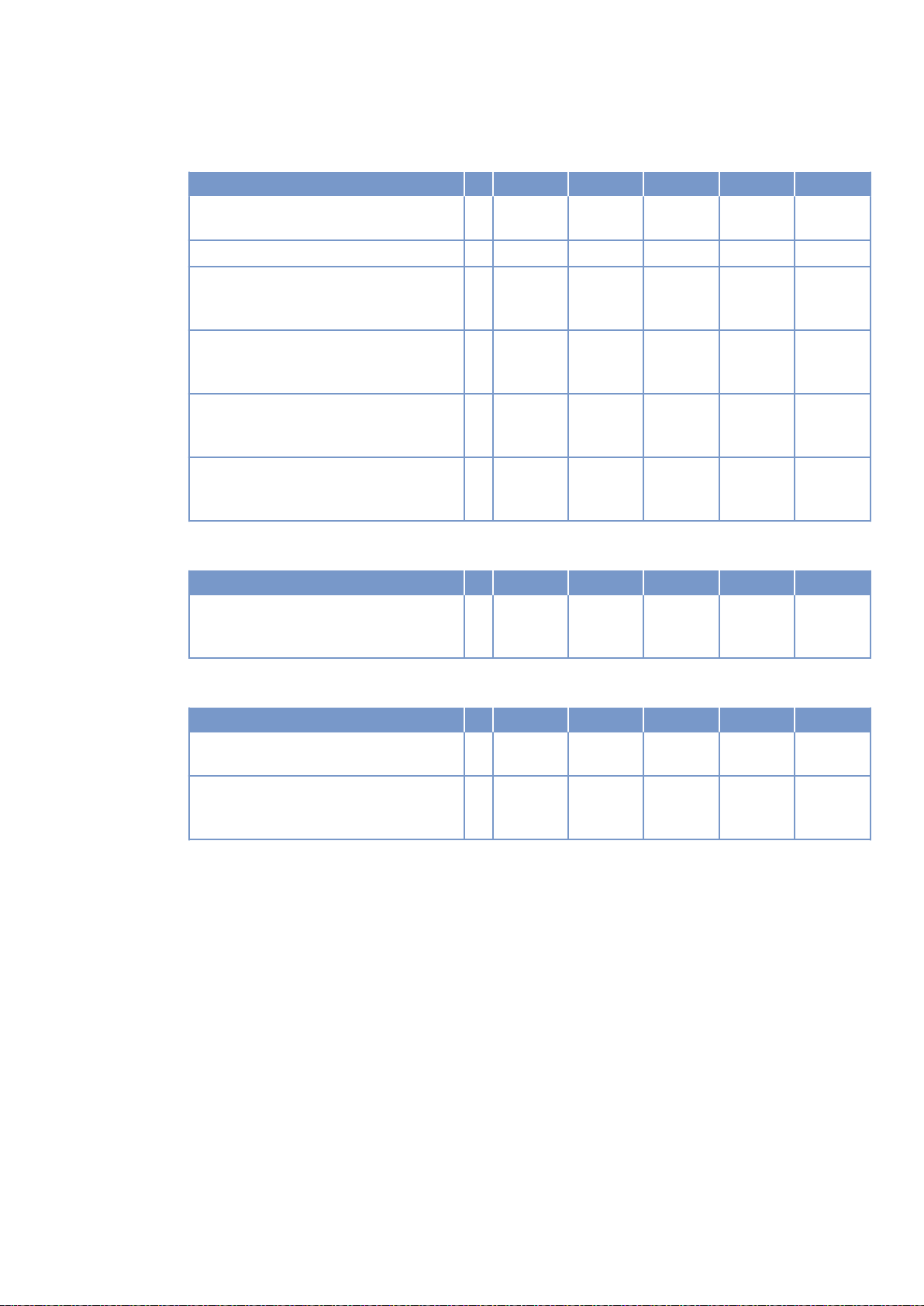
Capacities
Number of cylinders 12 12 12 12
Engine coolant capacity, engine side
R Liters 160 160 160 160
(without cooling equipment)
Charge-air coolant, engine side R Liters 40 40 40 40
Engine oil, total, for initial filling (stand‐
R Liters 260 260 260 260
ard oil system) (option: max. operating
inclinations)
Oil change quantity, max. (standard oil
R Liters
system) (option: max. operating inclina‐
tions)
Oil pan capacity at dipstick mark “min.”
L Liters 160 160 160 160
(standard oil system) (option: max. oper‐
ating inclinations)
Oil pan capacity at dipstick mark “max.”
L Liters 200 200 200 200
(standard oil system) (option: max. oper‐
ating inclinations)
Weights / main dimensions
Number of cylinders 12 12 12 12
Engine dry weight (basic engine configu‐
ration according to scope of delivery
specifications)
R kg 6200* 6200* 6200* 6200*
TIM-ID: 0000002873 - 002
Acoustics
Number of cylinders 12 12 12 12
Exhaust noise, unsilenced - BL (sound
power level LW, ISO 6798)
Engine surface noise with attenuated in‐
take noise (filter) - BL (sound power lev‐
el LW, ISO 6798)
R dB(A) 125 127 126 129
R dB(A) 121 123 122 124
M015710/04E 2012-09 | Technical Data | 47
Page 33
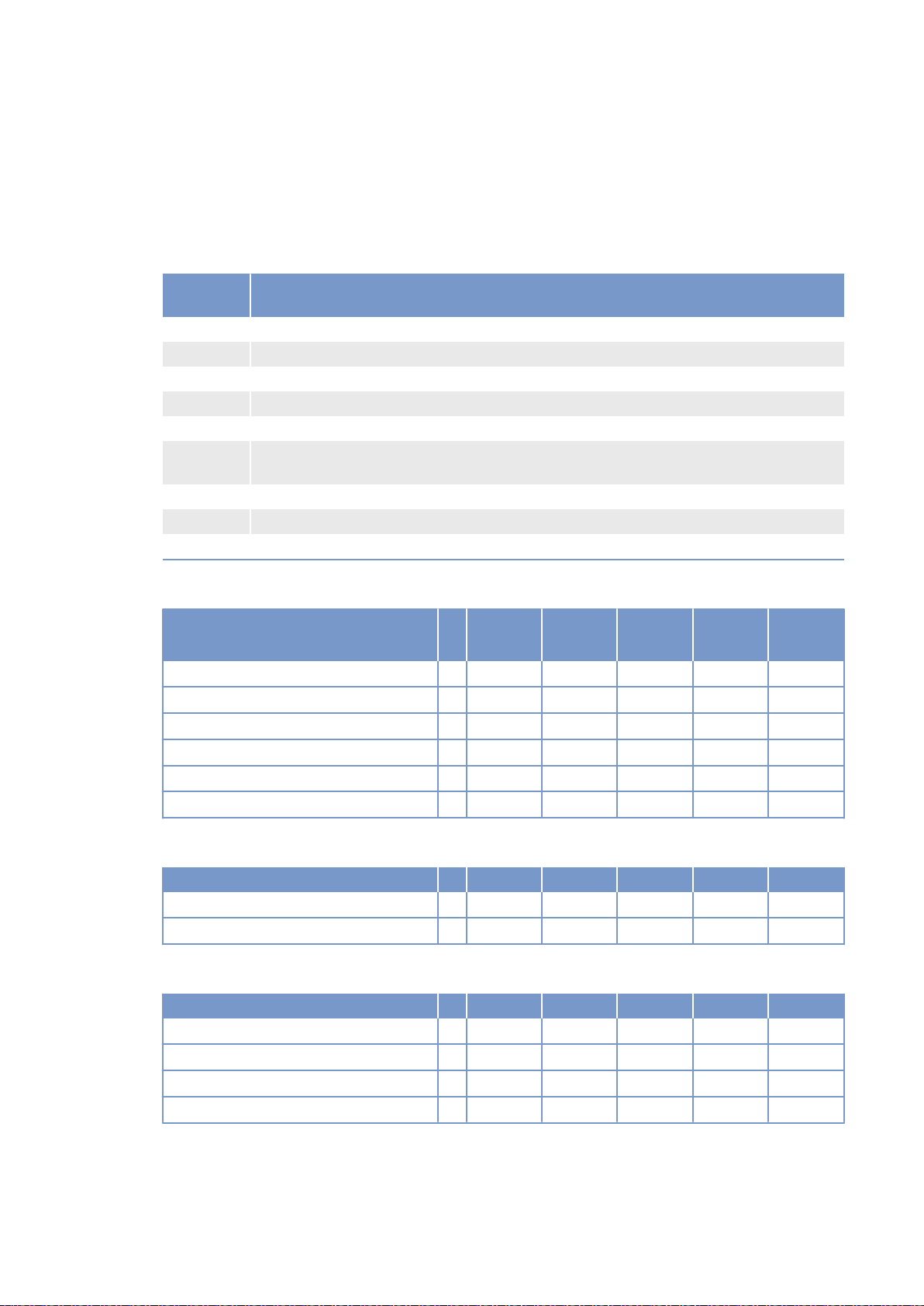
3.7 16 V 4000 Gx3 engine data: Standby operation 3D,
optimized fuel consumption
Explanation
Abbrevia‐
tion
DL Ref. value: Continuous power
BL Ref. value: Fuel stop power
A Design value
G Guaranteed value
R Guideline value
L Limit value, up to which the engine can be operated, without change (e.g. of power set‐
N Not yet defined value
- Not applicable
X Applicable
Meaning
tings).
Reference conditions
Engine model 16V
4000G23
Application group 3D 3D 3D 3D
Intake air temperature °C 25 25 25 25
Charge-air coolant temperature °C 55 55 55 55
Raw-water inlet temperature °C - - - -
Barometric pressure mbar 1000 1000 1000 1000
Site altitude above sea level m 100 100 100 100
16V
4000G43
16V
4000G63
16V
4000G83
Power-related data (power ratings are net brake power to ISO 3046)
Number of cylinders 16 16 16 16
Rated engine speed A rpm 1500 1800 1500 1800
Fuel stop power ISO 3046 A kW 1965 2280 2185 2500
General conditions (for maximum power)
Number of cylinders 16 16 16 16
Intake depression (new filter) A mbar 15 15 15 15
Intake depression, max. L mbar 50 50 50 50
Exhaust overpressure A mbar 30 30 30 30
Exhaust overpressure, max. L mbar 85 85 85 85
48 | Technical Data | M015710/04E 2012-09
TIM-ID: 0000002922 - 002
Page 34
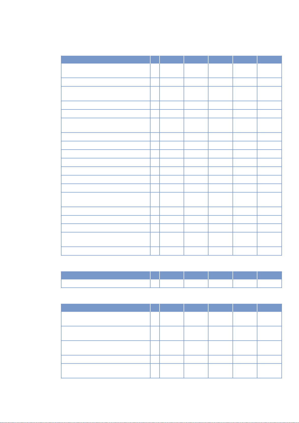
Model related data (basic design)
Number of cylinders 16 16 16 16
Engine with exhaust turbocharging
(ETC) and charge-air cooling (CAC)
Uncooled exhaust lines X X X X
Operating method: Four-stroke cycle,
diesel, single-action
Combustion method: direct fuel injection X X X X
Cooling method: Treated water X X X X
Direction of rotation: c.c.w. (facing driv‐
ing end)
Number of cylinders 16 16 16 16
Cylinder arrangement: V-angle Degrees 90 90 90 90
Bore mm 170 170 170 170
Stroke mm 210 210 210 210
Cylinder displacement Liters 4.77 4.77 4.77 4.77
Total displacement Liters 76.3 76.3 76.3 76.3
Compression ratio 16.5 16.5 16.5 16.5
Cylinder heads: individual cylinder
heads
Cylinder liners: wet, replaceable X X X X
Inlet valves per cylinder 2 2 2 2
Exhaust valves per cylinder 2 2 2 2
Standard housing connecting flange (en‐
SAE 00 00 00 00
gine main PTO)
Flywheel interface DISC 21 21 21 21
X X X X
X X X X
X X X X
X X X X
TIM-ID: 0000002922 - 002
Combustion air / Exhaust gas
Number of cylinders 16 16 16 16
Charge-air pressure before cylinder - BL R bar abs 2.8 3.1 3.1 3.3
Coolant system (HT circuit)
Number of cylinders 16 16 16 16
Coolant temperature (at engine connec‐
tion: outlet to cooling equipment)
Coolant temperature after engine, warn‐
ing
Coolant temperature after engine, shut‐
down
Coolant antifreeze content, max. L % 50 50 50 50
Pressure loss in off-engine cooling sys‐
tem, max.
A °C 100 100 100 100
R °C 102 102 102 102
L °C 104 104 104 104
L bar 0.7 0.7 0.7 0.7
M015710/04E 2012-09 | Technical Data | 49
Page 35
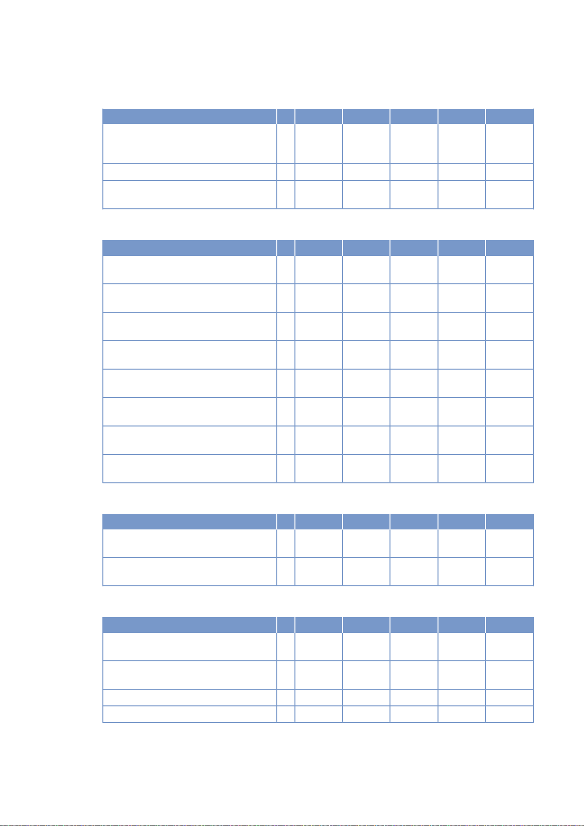
Coolant system (LT circuit)
Number of cylinders 16 16 16 16
Coolant temperature before intercooler
(at engine connection: from cooling
equipment)
Coolant antifreeze content, max. L % 50 50 50 50
Pressure loss in off-engine cooling sys‐
tem, max.
A °C 55 55 55 55
L bar 0.7 0.7 0.7 0.7
Lube oil system
Number of cylinders 16 16 16 16
Lube-oil operating temperature before
engine, from
Lube-oil operating temperature before
engine, to
Lube-oil temperature before engine,
warning
Lube-oil temperature before engine,
shutdown
Lube-oil operating pressure before en‐
gine, from
Lube-oil operating pressure before en‐
gine, to
Lube-oil operating pressure before en‐
gine, warning
Lube-oil operating pressure before en‐
gine, shutdown
R °C 89 88 88 88
R °C 95 95 94 94
R °C 97 97 97 97
L °C 99 99 99 99
R bar 4.2 4.7 4.2 4.7
R bar 5.5 6.5 5.5 6.5
R bar -- -- -- --
L bar -- -- -- --
Fuel system
Number of cylinders 16 16 16 16
Fuel pressure at engine inlet connection,
min. (when engine is starting)
Fuel pressure at engine inlet connection,
max. (when engine is starting)
L bar -0.1 -0.1 -0.1 -0.1
L bar 1.5 1.5 1.5 1.5
General operating data
Number of cylinders 16 16 16 16
Cold start capability: air temperature (w/
o start aid, w/o preheating) - (case A)
Coolant preheating: preheating tempera‐
ture (min.)
Firing speed, from R rpm 80 80 80 80
Firing speed, to R rpm 120 120 120 120
R °C 10 10 10 10
R °C 32 32 32 32
TIM-ID: 0000002922 - 002
50 | Technical Data | M015710/04E 2012-09
Page 36
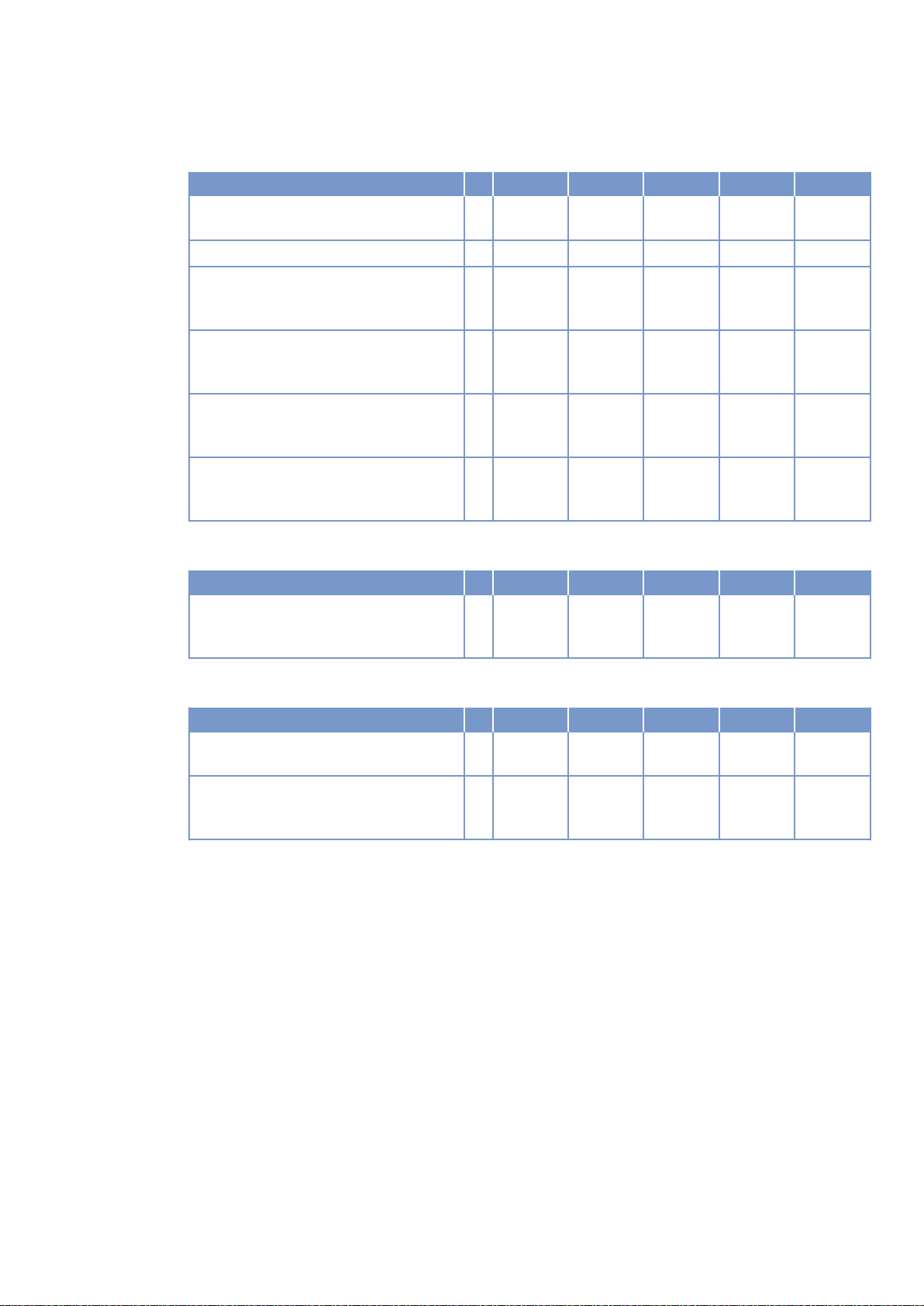
Capacities
Number of cylinders 16 16 16 16
Engine coolant capacity, engine side
R Liters 260 260 260 260
(without cooling equipment)
Charge-air coolant, engine side R Liters 50 50 50 50
Engine oil, total, for initial filling (stand‐
R Liters 300 300 300 300
ard oil system) (option: max. operating
inclinations)
Oil change quantity, max. (standard oil
R Liters 240 240 240 240
system) (option: max. operating inclina‐
tions)
Oil pan capacity at dipstick mark “min.”
L Liters 210 210 210 210
(standard oil system) (option: max. oper‐
ating inclinations)
Oil pan capacity at dipstick mark “max.”
L Liters 240 240 240 240
(standard oil system) (option: max. oper‐
ating inclinations)
Weights / main dimensions
Number of cylinders 16 16 16 16
Engine dry weight (basic engine configu‐
ration according to scope of delivery
specifications)
R kg 7700 7700 7700 7700
TIM-ID: 0000002922 - 002
Acoustics
Number of cylinders 16 16 16 16
Exhaust noise, unsilenced - BL (sound
power level LW, ISO 6798)
Engine surface noise with attenuated in‐
take noise (filter) - BL (sound power lev‐
el LW, ISO 6798)
R dB(A) 126 129 128 130
R dB(A) 128 125 125 126
M015710/04E 2012-09 | Technical Data | 51
Page 37
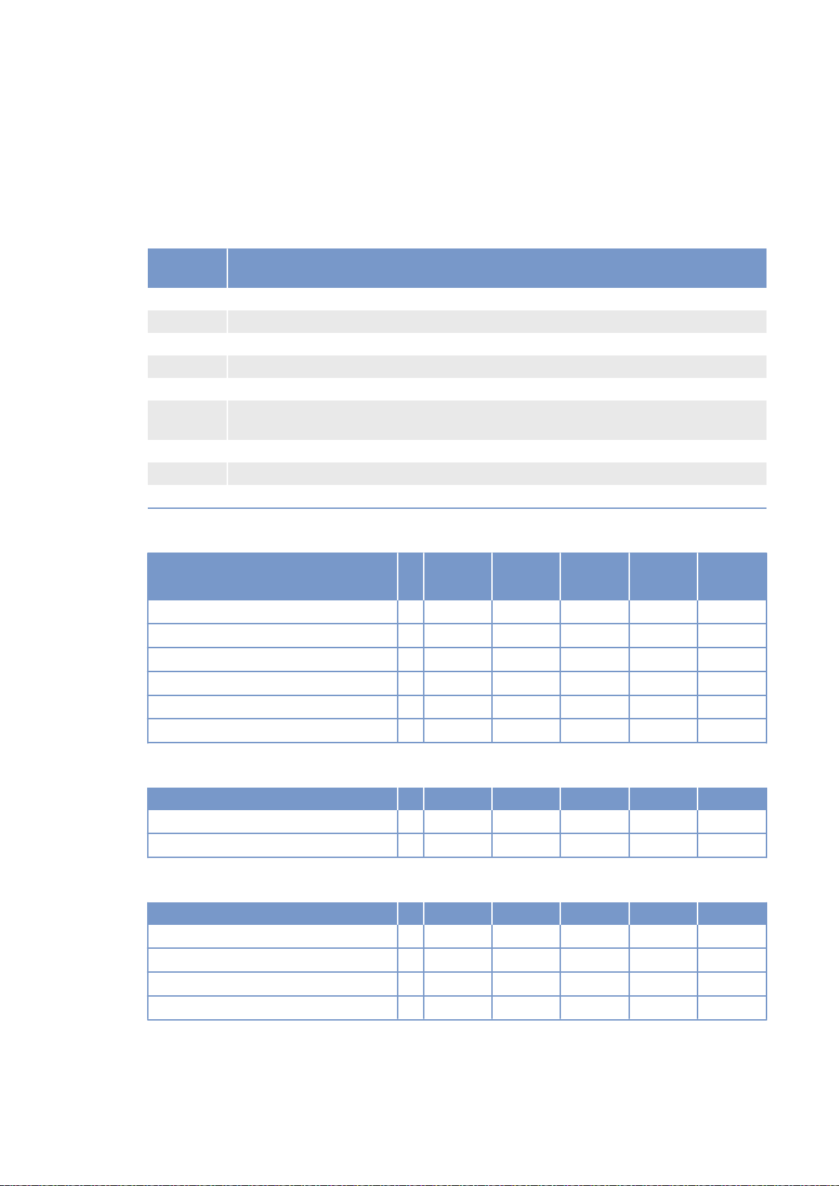
3.8 12/16 V 4000 Gx3 engine data: Standby operation 3D,
optimized exhaust emissions (EPA stage 2)
Explanation
Abbrevia‐
tion
DL Ref. value: Continuous power
BL Ref. value: Fuel stop power
A Design value
G Guaranteed value
R Guideline value
L Limit value, up to which the engine can be operated, without change (e.g. of power set‐
N Not yet defined value
- Not applicable
X Applicable
Meaning
tings).
Reference conditions
Engine model 12V
4000G43
Application group 3D 3D 3D 3D
Intake air temperature °C 25 25 25 25
Charge-air coolant temperature °C 45 45 45 45
Raw-water inlet temperature °C - - - -
Barometric pressure mbar 1000 1000 1000 1000
Site altitude above sea level m 100 100 100 100
12V
4000G83
16V
4000G43
16V
4000G83
Power-related data (power ratings are net brake power to ISO 3046)
Number of cylinders 12 12 16 16
Rated engine speed A rpm 1800 1800 1800 1800
Fuel stop power ISO 3046 A kW 1736 1910 2280 2500
General conditions (for maximum power)
Number of cylinders 12 12 16 16
Intake depression (new filter) A mbar 15 15 15 15
Intake depression, max. L mbar 50 50 50 50
Exhaust overpressure A mbar 30 30 30 30
Exhaust overpressure, max. L mbar 85 85 85 85
52 | Technical Data | M015710/04E 2012-09
TIM-ID: 0000002955 - 002
Page 38
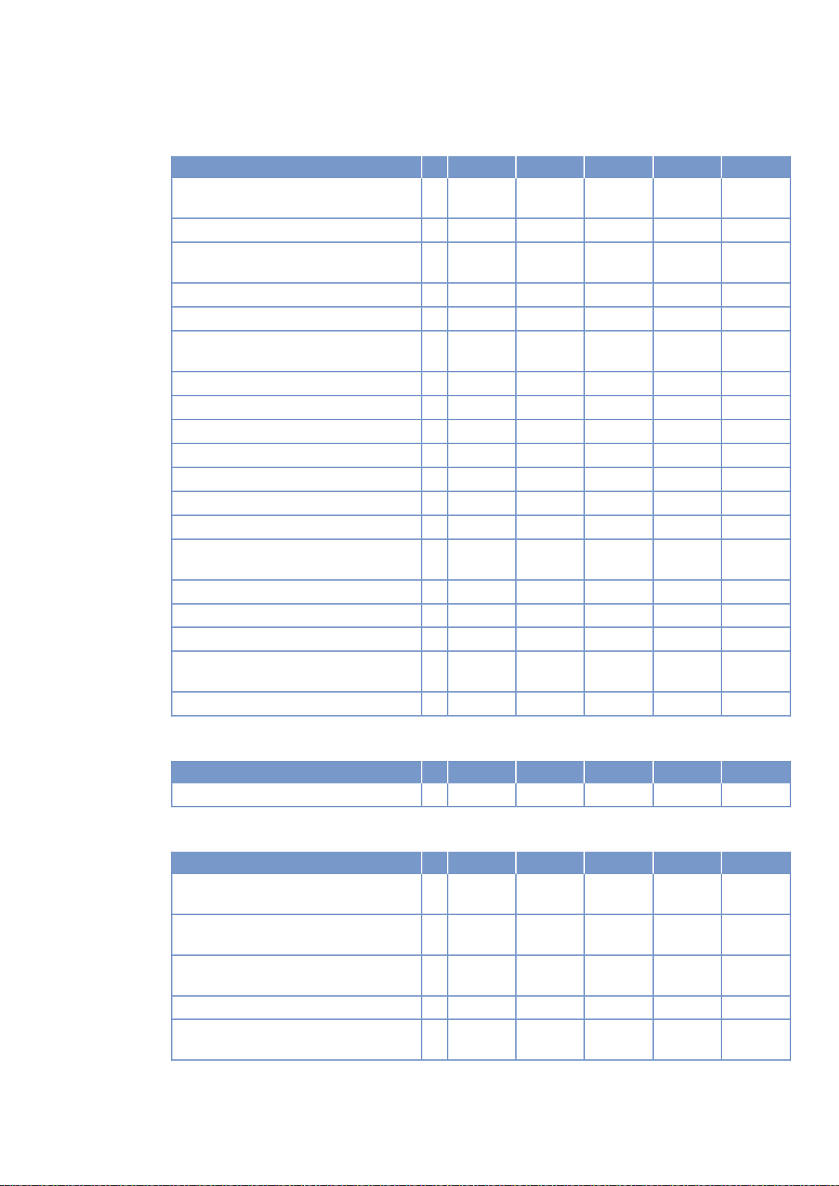
Model related data (basic design)
Number of cylinders 12 12 16 16
Engine with exhaust turbocharging
(ETC) and charge-air cooling (CAC)
Uncooled exhaust lines X X X X
Operating method: Four-stroke cycle,
diesel, single-action
Combustion method: direct fuel injection X X X X
Cooling method: Treated water X X X X
Direction of rotation: c.c.w. (facing driv‐
ing end)
Number of cylinders 12 12 16 16
Cylinder arrangement: V-angle Degrees 90 90 90 90
Bore mm 170 170 170 170
Stroke mm 210 210 210 210
Cylinder displacement Liters 4.77 4.77 4.77 4,77
Total displacement Liters 57.2 57.2 76,3 76.3
Compression ratio 16.5 16.5 16.5 16.5
Cylinder heads: individual cylinder
heads
Cylinder liners: wet, replaceable X X X X
Inlet valves per cylinder 2 2 2 2
Exhaust valves per cylinder 2 2 2 2
Standard housing connecting flange (en‐
SAE 00 00 00 00
gine main PTO)
Flywheel interface DISC 21 21 21 21
X X X X
X X X X
X X X X
X X X X
TIM-ID: 0000002955 - 002
Combustion air / Exhaust gas
Number of cylinders 12 12 16 16
Charge-air pressure before cylinder - BL R bar abs 3.2 3.3 3.2 3.3
Coolant system (HT circuit)
Number of cylinders 12 12 16 16
Coolant temperature (at engine connec‐
tion: outlet to cooling equipment)
Coolant temperature after engine, warn‐
ing
Coolant temperature after engine, shut‐
down
Coolant antifreeze content, max. L % 50 50 50 50
Pressure loss in off-engine cooling sys‐
tem, max.
A °C 100 100 100 100
R °C 102 102 102 102
L °C 104 104 104 104
L bar 0.7 0.7 0.7 0.7
M015710/04E 2012-09 | Technical Data | 53
Page 39
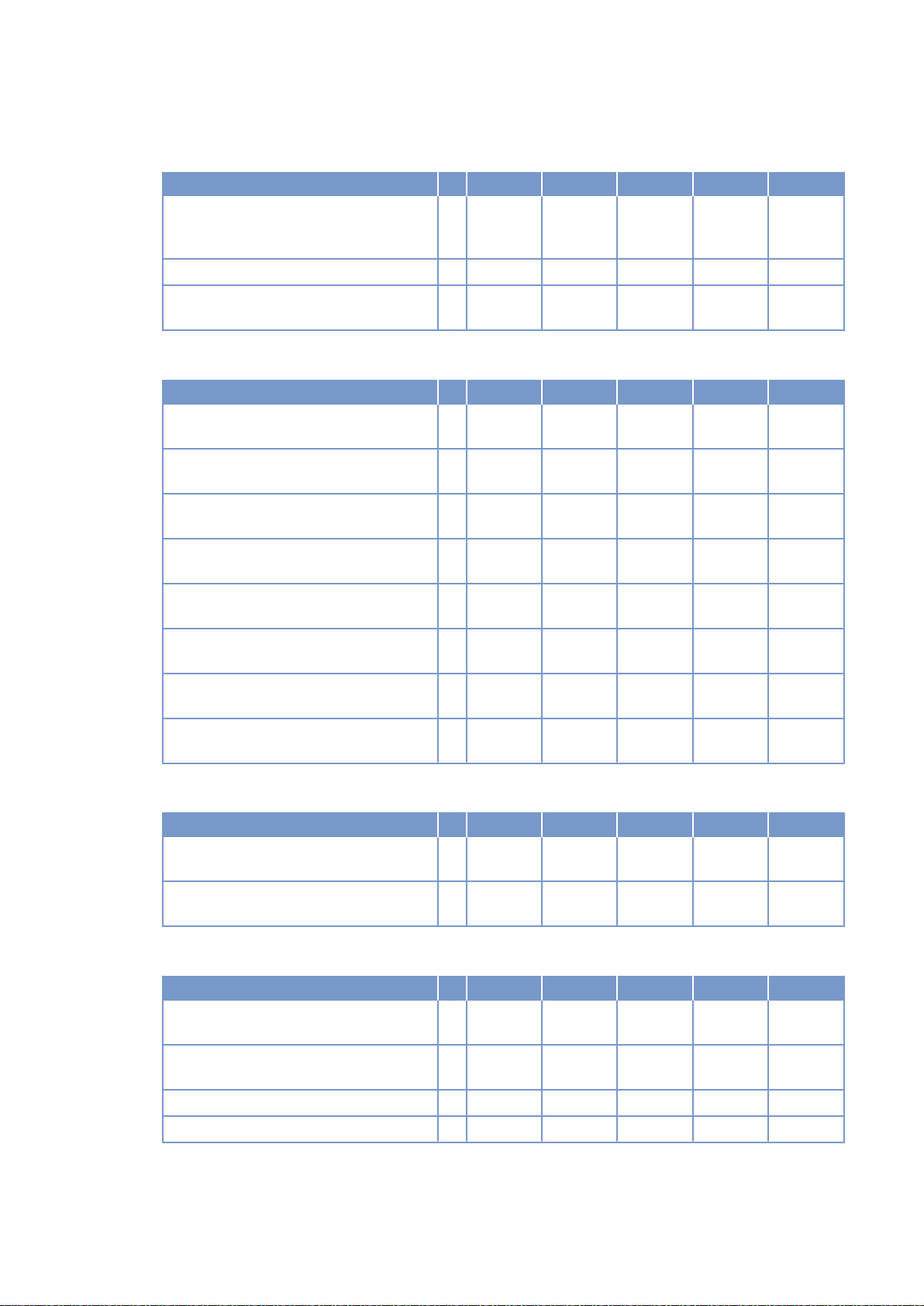
Coolant system (LT circuit)
Number of cylinders 12 12 16 16
Coolant temperature before intercooler
(at engine connection: from cooling
equipment)
Coolant antifreeze content, max. L % 50 50 50 50
Pressure loss in off-engine cooling sys‐
tem, max.
A °C 45 45 45 45
L bar 0.7 0.7 0.7 0.7
Lube oil system
Number of cylinders 12 12 16 16
Lube-oil operating temperature before
engine, from
Lube-oil operating temperature before
engine, to
Lube-oil temperature before engine,
warning
Lube-oil temperature before engine,
shutdown
Lube-oil operating pressure before en‐
gine, from
Lube-oil operating pressure before en‐
gine, to
Lube-oil operating pressure before en‐
gine, warning
Lube-oil operating pressure before en‐
gine, shutdown
R °C 88 88 88 88
R °C 98 98 94 94
R °C 99 99 97 97
L °C 101 101 99 99
R bar 5.0 5.0 4.7 4.7
R bar 7.0 7.0 6.5 6.5
R bar -- -- -- --
L bar -- -- -- --
Fuel system
Number of cylinders 12 12 16 16
Fuel pressure at engine inlet connection,
min. (when engine is starting)
Fuel pressure at engine inlet connection,
max. (when engine is starting)
L bar -0.1 -0.1 -0.1 -0.1
L bar 1.5 1.5 1.5 1.5
General operating data
Number of cylinders 12 12 16 16
Cold start capability: air temperature (w/
o start aid, w/o preheating) - (case A)
Coolant preheating: preheating tempera‐
ture (min.)
Firing speed, from R rpm 80 80 80 80
Firing speed, to R rpm 120 120 120 120
R °C 10 10 10 10
R °C 32 32 32 32
TIM-ID: 0000002955 - 002
54 | Technical Data | M015710/04E 2012-09
Page 40
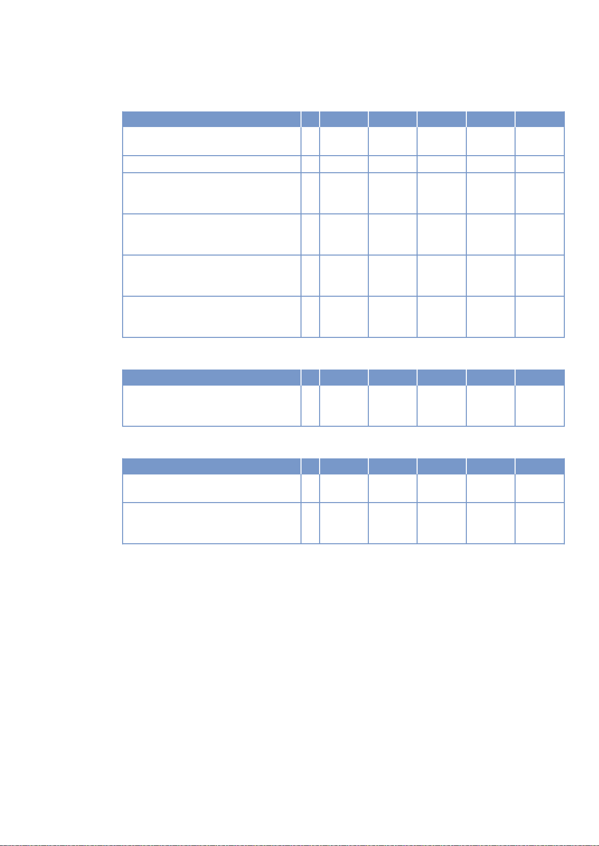
Capacities
Number of cylinders 12 12 16 16
Engine coolant capacity, engine side
R Liters 160 160 260 260
(without cooling equipment)
Charge-air coolant, engine side R Liters 40 40 50 50
Engine oil, total, for initial filling (stand‐
R Liters 260 260 300 300
ard oil system) (option: max. operating
inclinations)
Oil change quantity, max. (standard oil
R Liters 240 240
system) (option: max. operating inclina‐
tions)
Oil pan capacity at dipstick mark “min.”
L Liters 160 160 210 210
(standard oil system) (option: max. oper‐
ating inclinations)
Oil pan capacity at dipstick mark “max.”
L Liters 200 200 240 240
(standard oil system) (option: max. oper‐
ating inclinations)
Weights / main dimensions
Number of cylinders 12 12 16 16
Engine dry weight (basic engine configu‐
ration according to scope of delivery
specifications)
R kg 6200* 6200* 7700 7700
TIM-ID: 0000002955 - 002
Acoustics
Number of cylinders 12 12 16 16
Exhaust noise, unsilenced - BL (sound
power level LW, ISO 6798)
Engine surface noise with attenuated in‐
take noise (filter) - BL (sound power lev‐
el LW, ISO 6798)
R dB(A) 127 129 129 130
R dB(A) 123 124 125 126
M015710/04E 2012-09 | Technical Data | 55
Page 41
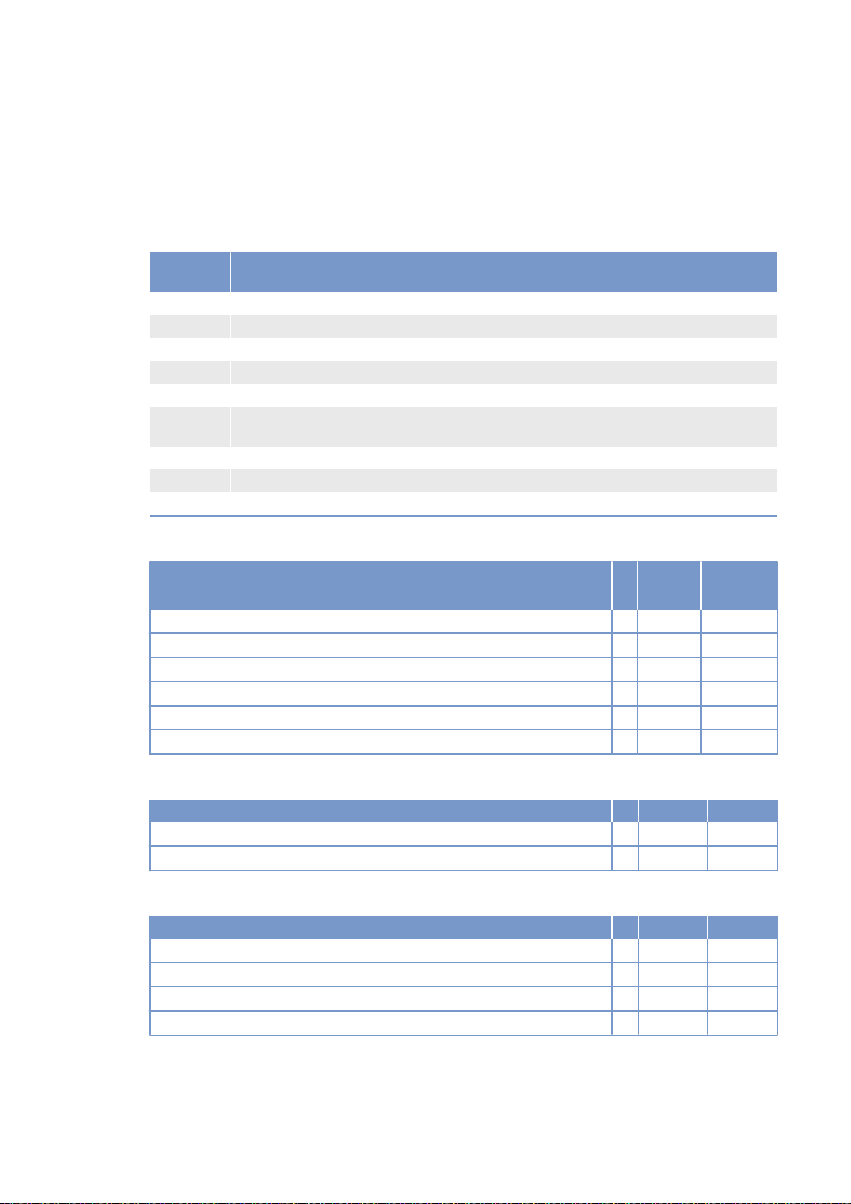
3.9 16 V 4000 G83L engine data: Standby operation 3D,
optimized fuel consumption
Explanation
Abbrevia‐
tion
DL Ref. value: Continuous power
BL Ref. value: Fuel stop power
A Design value
G Guaranteed value
R Guideline value
L Limit value, up to which the engine can be operated, without change (e.g. of power set‐
N Not yet defined value
- Not applicable
X Applicable
Meaning
tings).
Reference conditions
Engine model 16V
4000G83L
Application group 3D
Intake air temperature °C 25
Charge-air coolant temperature °C 45
Raw water inlet temperature °C -
Barometric pressure mbar 1000
Site altitude above sea level m 100
Power-related data (power ratings are net brake power to ISO 3046)
Number of cylinders 16
Rated engine speed A rpm 1800
Fuel stop power ISO 3046 A kW 2740
General conditions (for maximum power)
Number of cylinders 16
Intake depression (new filter) A mbar 15
Intake depression, max. L mbar 30
Exhaust overpressure A mbar 30
Exhaust overpressure, max. L mbar 85
56 | Technical Data | M015710/04E 2012-09
TIM-ID: 0000039902 - 001
Page 42
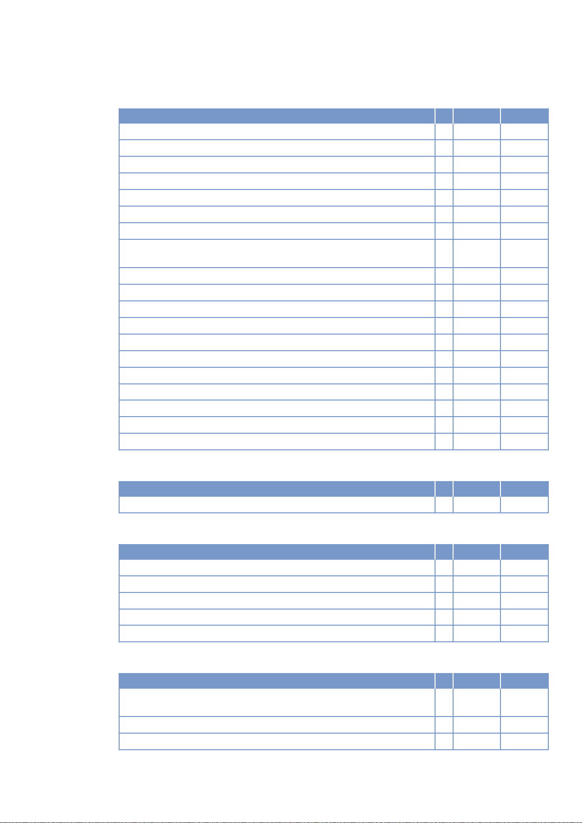
Model related data (basic design)
Number of cylinders 16
Engine with exhaust turbocharging (ETC) and charge-air cooling (CAC) X
Uncooled exhaust lines X
Operating method: Four-stroke cycle, diesel, single-action X
Combustion method: direct fuel injection X
Cooling method: Treated water X
Direction of rotation: c.c.w. (facing driving end) X
Number of cylinders 16
Cylinder arrangement: V-angle Degrees
(°)
Bore mm 170
Stroke mm 210
Cylinder displacement Liters 4.77
Total displacement Liters 76.3
Compression ratio 16.4
Inlet valves per cylinder 2
Cylinder heads: individual cylinder heads X
Cylinder liners: wet, replaceable X
Exhaust valves per cylinder 2
Standard housing connecting flange (engine main PTO) SAE 00
Flywheel interface (DISC) 21
90
TIM-ID: 0000039902 - 001
Combustion air / Exhaust gas
Number of cylinders 16
Charge-air pressure before cylinder - BL R bar abs 3.7
Coolant system (HT circuit)
Number of cylinders 16
Coolant temperature (at engine connection: outlet to cooling equipment) A °C 100
Coolant temperature after engine, warning R °C 102
Coolant temperature after engine, shutdown L °C 104
Coolant antifreeze content, max. L % 50
Pressure loss in off-engine cooling system, max. L bar 0.7
Coolant system (LT circuit)
Number of cylinders 16
Coolant temperature before intercooler (at engine connection: from cooling
equipment)
Coolant antifreeze content, max. L % 50
Pressure loss in off-engine cooling system, max. L bar 0.7
A °C 45
M015710/04E 2012-09 | Technical Data | 57
Page 43
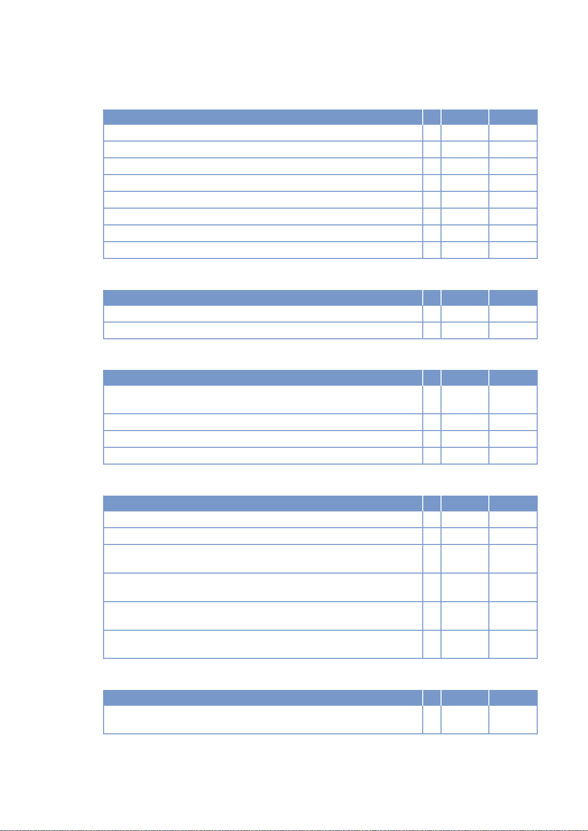
Lube oil system
Number of cylinders 16
Lube-oil operating temperature before engine, from R °C 88
Lube-oil operating temperature before engine, to R °C 94
Lube-oil temperature before engine, warning R °C 97
Lube-oil temperature before engine, shutdown L °C 99
Lube-oil operating pressure before engine, from R bar 4.7
Lube-oil operating pressure before engine, to R bar 6.5
Lube-oil operating pressure before engine, warning R bar -
Lube-oil operating pressure before engine, shutdown L bar -
Fuel system
Number of cylinders 16
Fuel pressure at engine inlet connection, min. (when engine is starting) L bar -0.1
Fuel pressure at engine inlet connection, max. (when engine is starting) L bar 1.5
General operating data
Number of cylinders 16
Cold start capability: air temperature (w/o start aid, w/o preheating) - (case
A)
Coolant preheating: preheating temperature (min.) R °C 32
Firing speed, from R rpm 80
Firing speed, to R rpm 120
R °C 10
Capacities
Number of cylinders 16
Engine coolant capacity, engine side (without cooling equipment) R Liters 175
Charge-air coolant, engine side R Liters 50
Engine oil capacity, initial filling (standard oil system) (Option: max. operat‐
ing inclinations)
Oil change quantity, max. (standard oil system) (Option: max. operating in‐
clinations)
Oil pan capacity at dipstick mark “min.” (standard oil system) (Option: max.
operating inclinations)
Oil pan capacity at dipstick mark “max.” (standard oil system) (Option: max.
operating inclinations)
R Liters 300
R Liters 240
L Liters 210
L Liters 240
Weights / main dimensions
Number of cylinders 16
Engine dry weight (basic engine configuration according to scope of deliv‐
ery specifications)
R kg 7700
TIM-ID: 0000039902 - 001
58 | Technical Data | M015710/04E 2012-09
Page 44

Acoustics
Number of cylinders 16
Exhaust noise, unsilenced - BL (sound power level LW, ISO 6798+3) R dB(A) 130
Engine surface noise with attenuated intake noise (filter) - BL (sound power
level LW, ISO 6798)
R dB(A) 126
TIM-ID: 0000039902 - 001
M015710/04E 2012-09 | Technical Data | 59
Page 45
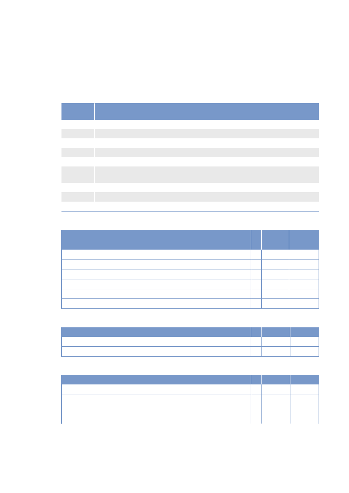
3.10 16 V 4000 G83L engine data: Standby operation 3D,
optimized exhaust emissions (EPA stage 2)
Explanation
Abbrevia‐
tion
DL Ref. value: Continuous power
BL Ref. value: Fuel stop power
A Design value
G Guaranteed value
R Guideline value
L Limit value, up to which the engine can be operated, without change (e.g. of power set‐
N Not yet defined value
- Not applicable
X Applicable
Meaning
tings).
Reference conditions
Engine model 16V
4000G83L
Application group 3D
Intake air temperature °C 25
Charge-air coolant temperature °C 45
Raw water inlet temperature °C -
Barometric pressure mbar 1000
Site altitude above sea level m 100
Power-related data (power ratings are net brake power to ISO 3046)
Number of cylinders 16
Rated engine speed A rpm 1800
Fuel stop power ISO 3046 A kW 2740
General conditions (for maximum power)
Number of cylinders 16
Intake depression (new filter) A mbar 15
Intake depression, max. L mbar 30
Exhaust overpressure A mbar 30
Exhaust overpressure, max. L mbar 85
60 | Technical Data | M015710/04E 2012-09
TIM-ID: 0000039906 - 001
Page 46
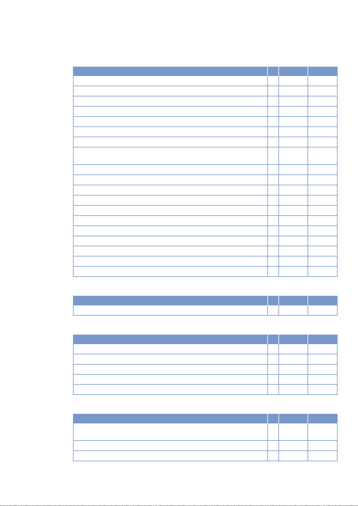
Model related data (basic design)
Number of cylinders 16
Engine with exhaust turbocharging (ETC) and charge-air cooling (CAC) X
Uncooled exhaust lines X
Operating method: Four-stroke cycle, diesel, single-action X
Combustion method: direct fuel injection X
Cooling method: Treated water X
Direction of rotation: c.c.w. (facing driving end) X
Number of cylinders 16
Cylinder arrangement: V-angle Degrees
(°)
Bore mm 170
Stroke mm 210
Cylinder displacement Liters 4.77
Total displacement Liters 76.3
Compression ratio 16.4
Inlet valves per cylinder 2
Cylinder heads: individual cylinder heads X
Cylinder liners: wet, replaceable X
Exhaust valves per cylinder 2
Standard housing connecting flange (engine main PTO) SAE 00
Flywheel interface (DISC) 21
90
TIM-ID: 0000039906 - 001
Combustion air / Exhaust gas
Number of cylinders 16
Charge-air pressure before cylinder - BL R bar abs 3,7
Coolant system (HT circuit)
Number of cylinders 16
Coolant temperature (at engine connection: outlet to cooling equipment) A °C 100
Coolant temperature after engine, warning R °C 102
Coolant temperature after engine, shutdown L °C 104
Coolant antifreeze content, max. L % 50
Pressure loss in off-engine cooling system, max. L bar 0.7
Coolant system (LT circuit)
Number of cylinders 16
Coolant temperature before intercooler (at engine connection: from cooling
equipment)
Coolant antifreeze content, max. L % 50
Pressure loss in off-engine cooling system, max. L bar 0.7
A °C 45
M015710/04E 2012-09 | Technical Data | 61
Page 47
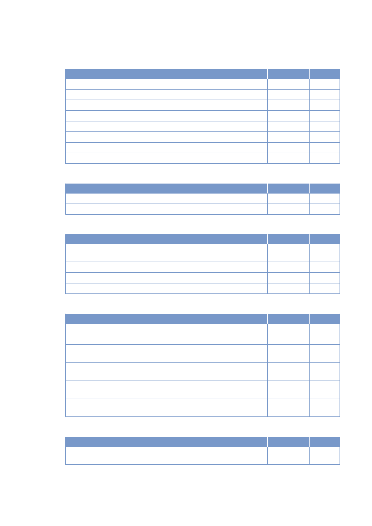
Lube oil system
Number of cylinders 16
Lube-oil operating temperature before engine, from R °C 88
Lube-oil operating temperature before engine, to R °C 94
Lube-oil temperature before engine, warning R °C 97
Lube-oil temperature before engine, shutdown L °C 99
Lube-oil operating pressure before engine, from R bar 4.7
Lube-oil operating pressure before engine, to R bar 6.5
Lube-oil operating pressure before engine, warning R bar -
Lube-oil operating pressure before engine, shutdown L bar -
Fuel system
Number of cylinders 16
Fuel pressure at engine inlet connection, min. (when engine is starting) L bar -0.1
Fuel pressure at engine inlet connection, max. (when engine is starting) L bar 1.5
General operating data
Number of cylinders 16
Cold start capability: air temperature (w/o start aid, w/o preheating) - (case
A)
Coolant preheating: preheating temperature (min.) R °C 32
Firing speed, from R rpm 80
Firing speed, to R rpm 120
R °C 10
Capacities
Number of cylinders 16
Engine coolant capacity, engine side (without cooling equipment) R Liters 175
Charge-air coolant, engine side R Liters 50
Engine oil capacity, initial filling (standard oil system) (Option: max. operat‐
ing inclinations)
Oil change quantity, max. (standard oil system) (Option: max. operating in‐
clinations)
Oil pan capacity at dipstick mark “min.” (standard oil system) (Option: max.
operating inclinations)
Oil pan capacity at dipstick mark “max.” (standard oil system) (Option: max.
operating inclinations)
R Liters 300
R Liters 240
L Liters 210
L Liters 240
Weights / main dimensions
Number of cylinders 16
Engine dry weight (basic engine configuration according to scope of deliv‐
ery specifications)
R kg 7700
TIM-ID: 0000039906 - 001
62 | Technical Data | M015710/04E 2012-09
Page 48

Acoustics
Number of cylinders 16
Exhaust noise, unsilenced - BL (sound power level LW, ISO 6798+3) R dB(A) 130
Engine surface noise with attenuated intake noise (filter) - BL (sound power
level LW, ISO 6798)
R dB(A) 126
TIM-ID: 0000039906 - 001
M015710/04E 2012-09 | Technical Data | 63
Page 49

3.11 Final compression pressure
Final compression pressure
Final compression pressure at 120 rpm 24 bar to 28 bar
64 | Technical Data | M015710/04E 2012-09
TIM-ID: 0000002820 - 001
Page 50
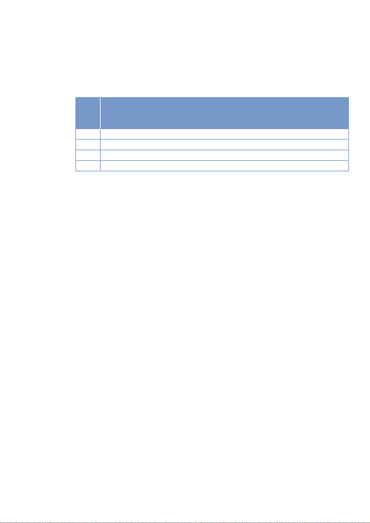
3.12 Firing order
Firing order
Num‐
ber of
cylin‐
ders
8V A1-B4-A4-A2-B3-A3-B2-B1
12V A1-B5-A5-B3-A3-B6-A6-B2-A2-B4-A4-B1
16 V A1-A7-B4-B6-A4-B8-A2-A8-B3-B5-A3-A5-B2-A6-B1-B7
20 V A1-B5-A8-B7-A5-B2-A7-B10-A2-B3-A10-B6-A3-B4-A6-B9-A4-B1-A9-B8
Firing order
TIM-ID: 0000002796 - 003
M015710/04E 2012-09 | Technical Data | 65
Page 51
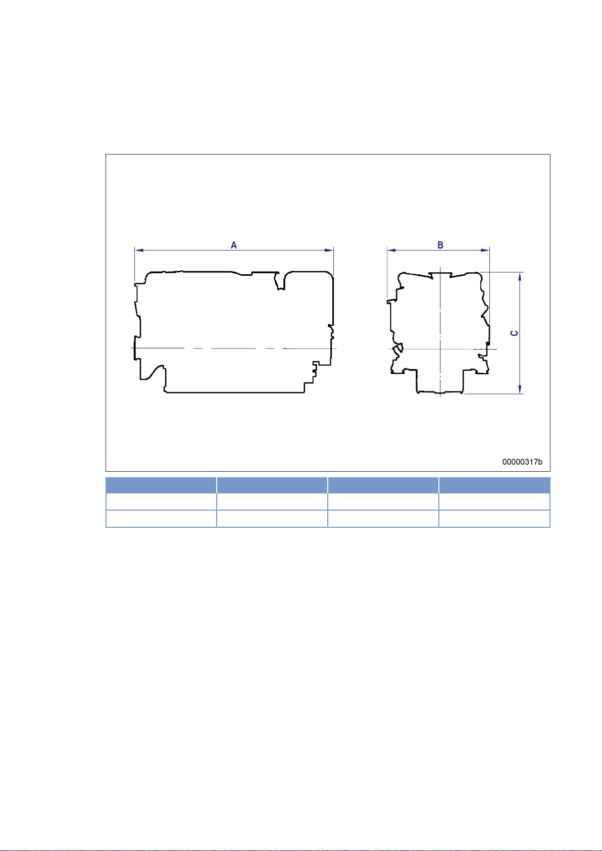
3.13 Engine – Main dimensions
Also valid for 12 V and 16 V engines.
Engine model Length (A) Width (B) Height (C)
12 V 4000 Gx3 approx. 2520 mm approx. 1660 mm approx. 2160 mm
16 V 4000 Gx3 approx. 2990 mm approx. 1660 mm approx. 2160 mm
TIM-ID: 0000002133 - 002
66 | Technical Data | M015710/04E 2012-09
Page 52
4 Operation
4.1 Putting the engine into operation after extended out-ofservice periods (>3 months)
Preconditions
☑ Engine is stopped and starting disabled.
☑ MTU Preservation and Represervation Specifications (A001070/..) are available.
Putting the PowerPack into operation after extended out-of-service-periods (>3
months)
Item Action
Engine Depreserve (→ MTU Fluids and Lubricants Specifications A001070/..).
Valve gear Lubricate valve gear every ≥ 6 months (→ Page 140).
Lube oil system Check engine oil level (→ Page 169).
Fuel prefilter Fill with fuel (→ Page 159).
Fuel prefilter, pressure
gauge
Coolant circuit If engine is out of service for more than one year, change engine coolant
Align adjustable pointer with position of pressure indicator (→ Page 155).
(→ Page 177).
TIM-ID: 0000002195 - 002
Change charge-air coolant (→ Page 185).
Coolant circuit Check engine coolant level (→ Page 176);
Check charge-air coolant level (→ Page 184).
Coolant circuit Heat engine coolant with coolant preheating unit.
Engine governor Check plug-in connections (→ Page 197).
Monitoring system Carry out lamp test (see manufacturer's documentation).
Engine/generator control
system
HP fuel pump Only for engines without oil priming pump
Switch ON;
Select operating mode, e.g. MANUAL OPERATION, AUTOMATIC OPER‐
ATION.
Fill HP fuel pump with new engine oil (→ Page 145).
M015710/04E 2012-09 | Operation | 67
Page 53
4.2 Putting the engine into operation after scheduled out-ofservice-period
Preconditions
☑ Engine is stopped and starting disabled.
Putting the engine into operation
Item Task
Lube oil system Check oil level (→ Page 169);
Cooling system Check engine coolant level (→ Page 176);
Check charge-air coolant level (→ Page 184).
Cooling system Preheat coolant with preheating unit.
Fuel prefilter Drain (→ Page 156).
Monitoring equipment Carry out lamp test (see manufacturer's documentation).
Engine/generator control
system
Switch ON;
Select operating mode, e.g. MANUAL OPERATION, AUTOMATIC OPER‐
ATION.
68 | Operation | M015710/04E 2012-09
TIM-ID: 0000002677 - 001
Page 54
4.3 Start engine in manual mode (testing mode)
Preconditions
☑ Generator (if provided) not connected to network.
☑ External start interlock is not activated.
DANGER
WARNING
Unguarded rotating and moving engine components.
Risk of serious injury – danger to life!
• Before barring or starting the engine, make sure that nobody is in the danger zone.
Engine noise above 85 dB (A).
Risk of damage to hearing!
• Wear ear protectors.
Preparation
Item Task
Operating mode selector
switch (if provided)
Preheating pump (if provid‐
ed)
Change to manual mode.
Switch ON.
Starting the engine
Item Task
Switchgear cabinet, control
panel etc. (depending on
manufacturer)
If coolant temperature is
• > 40 °C (with preheating equipment), or
• > 5 °C (without preheating equipment):
TIM-ID: 0000002226 - 002
Press start button.
• Automatic starting sequence is performed;
• Engine speed display instrument indicates increasing crankshaft speed;
• After the starting sequence is completed, engine is running at rated
speed.
Connect generator to network (if provided), run engine to reach operating
temperature )
Item Task
Switchgear cabinet, control
panel etc. (depending on
manufacturer)
Engine Apply full load only after engine has reached operating temperature (cool‐
Close the generator circuit breaker.
ant temperature approx. 75 °C).
M015710/04E 2012-09 | Operation | 69
Page 55
4.4 Safety system – Override
CAUTION
CAUTION
Safety functions and engine shutdown alarms will be disregarded.
Serious damage to plant!
• Initiate emergency start only in emergency situations.
Inadmissible operational condition.
Major material damage!
• Use override function only in hazardous situations to ensure full capability in case of engine mal‐
functions.
Preparation
Note: This function is only available when a pushbutton is provided.
Bypassing the safety system (Override)
Item Action
Switchgear cabinet, control
panel etc. (depending on
manufacturer)
Switchgear cabinet, control
panel etc. (depending on
manufacturer)
Control and display panels During operation, check the displayed operational data (speed, tempera‐
Activate pushbutton for Override input of the ECU.
• Certain shutdown criteria and/or starting prerequisites are ignored.
Actuate start button, for further starting sequence, refer to engine start
(→ Page 69).
ture, pressures).
Constantly monitor plant limit values.
TIM-ID: 0000000984 - 002
70 | Operation | M015710/04E 2012-09
Page 56
4.5 Starting the engine in emergency situations (override mode)
CAUTION
Safety functions and engine shutdown alarms will be disregarded.
Serious damage to plant!
• Initiate emergency start only in emergency situations.
Preparation
Item Task
Operating mode switch Set to emergency mode.
Starting the engine in emergency situations
Item Task
Control cabinet Actuate switch/button for ECU override input.
Control cabinet • Automatic starting procedure is performed; any safety functions and
alarms leading to engine shutdown are disregarded;
• Tachometer indicates increasing crankshaft speed;
• Engine is running at rated speed when the starting sequence is com‐
pleted.
Connecting the generator (if fitted) to mains
TIM-ID: 0000010665 - 001
Item Task
Control cabinet If generator is not connected to mains: Close generator circuit breaker.
Engine Operate engine at rated power.
M015710/04E 2012-09 | Operation | 71
Page 57
4.6 Operational checks
DANGER
WARNING
Unguarded rotating and moving engine components.
Risk of serious injury – danger to life!
• Take special care when working on a running engine.
Engine noise above 85 dB (A).
Risk of damage to hearing!
• Wear ear protectors.
Operational checks
Item Measure
Control and display panels Check readings of operational data (speed, temperature, pressures).
Engine oil Check engine oil level (→ Page 169)
Engine under load
Engine at nominal speed
Fuel prefilter Check reading on differential pressure gauge to ensure that maximum
Exhaust system Check exhaust color (→ Page 79).
Intercooler Check condensate drain(s) for water discharge and obstruction
Air filter Check signal ring position of contamination indicator (→ Page 165).
Check engine/plant and piping for leaks, repair leaky pipes with the engine
stopped (exhaust lines and turbocharger turbine housings may be red-hot.
If the maximum exhaust temperatures are not exceeded, no restrictions in
engine operation are required)
Check for abnormal running noises and vibration.
permissible value is not exceeded (→ Page 155).
(→ Page 161).
Replace air filter (→ Page 162) if the signal ring is completely visible in the
contamination indicator control window.
Engine coolant pump Check relief bore (→ Page 182).
Charge-air coolant pump Check relief bore (→ Page 190).
Compressed-air system (if
installed)
Check operating pressure on pressure gauge;
Always fill compressed-air tank to max. pressure;
Drain condensate from compressed-air tank, pressure drop must not ex‐
ceed 1 bar.
TIM-ID: 0000002258 - 003
72 | Operation | M015710/04E 2012-09
Page 58
4.7 Stop engine in manual mode (testing mode)
Preconditions
☑ Generator (if provided) not connected to network.
☑ Engine is running in manual mode.
CAUTION
Stopping the engine when it is running at full load causes extreme stress to the engine.
Risk of overheating, damage to components!
• Before stopping the engine, operate it at idle speed until operating temperatures decrease and
stable values are indicated.
Preparing the generator drive (only with generator breaker)
Item Task
Engine After opening the generator breaker (if provided), allow to cool down off-
load for approx. 5 minutes.
Preparing the pump drive (diesel-mechanical/diesel-electric)
Item Task
Engine Allow to cool down for approx. 5 minutes at reduced engine speed. Ob‐
serve natural resonance of engine (installation-dependent)!
Stopping the engine
Item Task
Switchgear cabinet, control
panel etc. (depending on
manufacturer)
Press stop button.
• Automatic stopping sequence is performed;
• Engine is stopped.
TIM-ID: 0000002285 - 001
After stopping the engine
Item Task
Coolant pump Allow to run on for sufficient time after stopping.
M015710/04E 2012-09 | Operation | 73
Page 59
4.8 Emergency stop
CAUTION
An emergency stop causes extreme stress to the engine.
Risk of overheating, damage to components!
• Initiate emergency stop only in emergency situations.
Emergency stop from LOP
Item Task
EMERGENCY STOP but‐
ton
Press.
• Engine is stopped by switching off power supply to ECU;
• Signalization (e.g. by horn, flashing lamp) is released.
After emergency stop from LOP
Item Task
Switching cabinet, control
panel etc. (depending on
manufacturer)
Press button for alarm acknowledgement.
• Audible and visual signalization stops.
74 | Operation | M015710/04E 2012-09
TIM-ID: 0000002305 - 002
Page 60

4.9 After stopping the engine – Engine remains ready for
operation
After stopping the engine
Item Action
Engine/generator/pump
control
Select operating mode, e.g. MANUAL, AUTOMATIC OPERATION.
TIM-ID: 0000000983 - 002
M015710/04E 2012-09 | Operation | 75
Page 61

4.10 After stopping the engine – putting the engine out of service
Preconditions
☑ MTU-Preservation and Represervation Specifications (A001070/..) are available.
After stopping the engine
Item Task
Cooling system Drain engine coolant (→ Page 178);
Drain charge-air coolant (→ Page 186) if:
• freezing temperatures are expected and the engine is to remain out of
service for an extended period and coolant has no antifreeze additive;
• the engine room is not heated;
• the coolant is not maintained at a suitable temperature;
• the antifreeze concentration is insufficient for the engine-room tempera‐
ture;
• antifreeze concentration is 50 % and engine-room temperature is below
-40°C.
Engine/generator/pump
controller
Air intake and exhaust sys‐
tem
Switch OFF.
If the engine is to remain out of service for more than 1 week, seal the
engine's air and exhaust sides. If the engine is to remain out of service for
more than 1 month, preserve engine (→ MTU-Preservation and Represer‐
vation Specifications A001070/..).
76 | Operation | M015710/04E 2012-09
TIM-ID: 0000002706 - 002
Page 62
4.11 Plant cleaning
Preconditions
☑ Engine is stopped and starting disabled.
☑ Operating voltage is not present.
Special tools, Material, Spare parts
Designation / Use Part No. Qty.
WARNING
WARNING
CAUTION
NOTICE
Steam jet cleaner
Cleaner (Hakupur 312)
Compressed air
Risk of injury!
• Do not direct compressed-air jet at persons.
• Wear protective goggles / safety mask and ear protectors.
Water jet.
Risk of injury and scalding!
• Do not direct water jet at persons.
• Wear protective clothing, gloves, and goggles / safety mask.
Excessive reaction time of cleaning agents on components.
Damage to component!
• Observe manufacturer's instructions.
• Wear protective clothing, gloves, and goggles / safety mask.
Dry with compressed air.
Damage to component!
• Never aim compressed air directly at electronic components.
- 1
30390 1
TIM-ID: 0000010171 - 024
Note: Never aim compressed air directly at electronic components.
Plant cleaning
1. Carry out plant cleaning only in areas where an appropriate oil separator is provided (environmental pro‐
tection).
2. Prior to putting the cleaning unit into operation, read the Operating Instructions of the water/steam jet unit
carefully and observe the safety precautions.
3. During external cleaning of the plant with water/steam-jet units, the pressure of the high-pressure jet
(cleaning jet) must not exceed 50 bar. A minimum distance between spray nozzle and plant of 1 m must
be observed. The temperature of the cleaning medium must not exceed 80 °C.
4. For external cleaning with high-pressure jet, use a flat-mouth nozzle only.
5. Carry out external cleaning as follows:
a) Seal all openings in a suitable fashion.
b) Remove coarse dirt.
c) Spray on cleaner sparingly and leave it for 1 to 5 minutes.
d) Use the high-pressure jet to remove the loosened dirt.
e) Dry engine.
M015710/04E 2012-09 | Operation | 77
Page 63
5 Maintenance
5.1 Maintenance task reference table [QL1]
The maintenance tasks and intervals for this product are defined in the Maintenance Schedule. The
Maintenance Schedule is a stand-alone publication.
The task numbers in this table provide reference to the maintenance tasks specified in the Maintenance
Schedule.
Task Option Maintenance tasks
W0500 Check engine oil level. (→ Page 169)
W0501 Visually inspect engine for leaks and general condition. (→ Page 72)
W0502 X Check intercooler drain(s). (→ Page 161)
W0503 Check signal ring position of service indicator on air fil‐
ter.
W0505 Check relief bores of water pump(s). (→ Page 182)
W0506 Check engine for abnormal running noises, exhaust col‐
or and vibrations.
W0507 X Drain water and contaminants from fuel prefilter. (→ Page 72)
W0508 X Check reading on differential pressure gage of fuel pre‐
filter.
W0534 Carry out test run, minimum duration: until steady-state
temperature is reached, no less than 1/3 load (monthly).
W1001 Replace fuel filter or fuel filter element. (→ Page 153)
W1005 Replace air filter. (→ Page 162)
W1006 Replace fuel injectors. (→ Page 146)
W1008 Replace engine oil filter when changing engine oil, or
when the interval (years) is reached, at the latest.
W1009 X Check layer thickness of the oil residue, clean out and
replace filter sleeve.
W1011 Perform endoscopic examination. (→ Page 134)
W1046 Crankcase breather: Replace filter or filter element. (→ Page 138)
W1207 Check and adjust valve clearance. Attention!First adjust‐
ment after 1,000 operating hours.
W1241 Check condition of belt drive and replace if necessary;
adjust belt tension.
W1463 Check general condition of engine mounting (visual in‐
spection).
W1714 X Check and clean oil indicator filter. (→ Page 172)
Table 1: Maintenance task reference table [QL1]
(→ Page 165)
(→ Page 72)
(→ Page 72)
(→ Page 133)
(→ Page 171)
(→ Page 174)
(→ Page 141)
(→ Page 191)
(→ Page 194)
TIM-ID: 0000022705 - 003
78 | Maintenance | M015710/04E 2012-09
Page 64
6 Troubleshooting
6.1 Troubleshooting
Engine does not turn when starter is actuated
Component Probable cause Task
Battery Low or defective Charge or replace (see manufacturer's
Cable connections defective Check if cable connections are proper‐
Starter (electric) Engine wiring or starter defective Check cable connections for secure
Starter (compressed
air)
Engine wiring Defective Check (→ Page 195).
Engine/generator
control system
Engine Governor Plug-in connections are loose Check plug connections (→ Page 197).
Engine Running gear blocked (engine cannot
Cabling on starting valve or starter de‐
fective
Secure seating of assemblies or con‐
nectors not provided
be barred manually)
documentation).
ly secured (see manufacturer's docu‐
mentation).
seating,
Contact Service.
Check cable connections for secure
seating,
Contact Service.
Perform visual inspection (see manu‐
facturer's documentation).
Contact Service.
TIM-ID: 0000002537 - 001
Engine turns but does not fire
Component Probable cause Task
Starter (electric) Poor rotation by starter: Battery low or
defective
Starter (compressed
air)
Engine wiring Defective Check (→ Page 195).
Fuel system Not vented Vent fuel system (→ Page 152).
Engine Governor Defective Contact Service.
Poor rotation by starter: Air pressure
too low
Charge or replace battery (see manu‐
facturer's documentation).
Check compressed air system.
Engine fires unevenly
Component Probable cause Task
Fuel injection equip‐
ment
Engine wiring Defective Check (→ Page 195).
Fuel system Not vented Vent fuel system (→ Page 152).
Engine Governor Defective Contact Service.
Injector defective Replace (→ Page 146).
M015710/04E 2012-09 | Troubleshooting | 79
Page 65
Engine does not reach nominal speed
Component Probable cause Task
Fuel supply Fuel prefilter clogged Replace (→ Page 159).
Easy-change fuel filter clogged Replace (→ Page 153).
Air supply Air filter clogged Check signal ring position of service in‐
dicator (→ Page 165).
Fuel injection equip‐
ment
Engine wiring Defective Check (→ Page 195).
Engine Overloaded Contact Service.
Injector defective Replace (→ Page 146).
Engine speed not steady
Component Probable cause Task
Fuel injection equip‐
ment
Speed sensor Defective Contact Service.
Fuel system Not vented Vent fuel system (→ Page 152).
Engine Governor Defective Contact Service.
Injector defective Replace (→ Page 146).
Charge-air temperature too high
Component Probable cause Task
Engine coolant Incorrect coolant concentration Check (MTU test kit).
Intercooler Contaminated Contact Service.
Engine room Air-intake temperature too high Check fans and air supply / ventilation
ducts.
Charge air pressure too low
Component Probable cause Task
Air supply Air filter clogged Check signal ring position of service in‐
dicator (→ Page 165).
Intercooler Contaminated Contact Service.
Exhaust turbocharger Defective Contact Service.
Coolant leaks on intercooler
Component Probable cause Task
Intercooler Leaking, major coolant discharge Contact Service.
Exhaust gas black
Component Probable cause Task
Air supply Air filter clogged Check signal ring position of service in‐
Fuel injection equip‐
ment
Engine Overloaded Contact Service.
80 | Troubleshooting | M015710/04E 2012-09
Injector defective Replace (→ Page 146).
TIM-ID: 0000002537 - 001
dicator (→ Page 165).
Page 66
Exhaust gas blue
Component Probable cause Task
Engine oil Too much engine oil in the engine Drain engine oil (→ Page 167).
Oil separator of crankcase breather
Replace (→ Page 138).
contaminated
Exhaust turbocharg‐
Defective Contact Service.
er, cylinder head, pis‐
ton rings, cylinder lin‐
er
Exhaust gas white
Component Probable cause Task
Engine Not at operating temperature Run engine to reach operating temper‐
ature.
Fuel system Water in fuel Check fuel system on fuel prefilter.
Drain fuel prefilter (→ Page 156).
Intercooler Leaking Contact Service.
TIM-ID: 0000002537 - 001
M015710/04E 2012-09 | Troubleshooting | 81
Page 67
6.2 Engine governor ADEC (ECU 7) for Series 4000 genset
engines – Fault messages
003 – HI T-Fuel
ZKP-Number: 2.0122.931
Limit value 1
Cause Corrective action
Fuel temperature too high. u Contact Service.
004 – SS T-Fuel
ZKP-Number: 2.0122.932
Limit value 2
Cause Corrective action
Fuel temperature too high;
Engine stop.
u Contact Service.
005 – HI T-Charge Air
ZKP-Number: 2.0121.931
Limit value 1
Cause Corrective action
Charge-air temperature too high. 1. Reduce power.
2. Check intercooler.
006 – SS T-Charge Air
ZKP-Number: 2.0121.932
Limit value 2
Cause Corrective action
Charge-air temperature too high
Engine stop.
1. Reduce power.
2. Check intercooler.
009 – HI T-Coolant Intercooler
Limit value 1
Cause Corrective action
Coolant temperature in
intercooler too high.
82 | Troubleshooting | M015710/04E 2012-09
ZKP-Number: 2.0124.931
u Reduce power.
TIM-ID: 0000008506 - 002
Page 68
010 – SS T-Coolant Intercooler
ZKP-Number: 2.0124.932
Limit value 2
Cause Corrective action
Coolant temperature in
intercooler too high;Engine stop.
u Reduce power.
015 – LO P-Lube Oil
ZKP-Number: 2.0100.921
Limit value 1
Cause Corrective action
Lube oil pressure too low. u Check oil level, top up as necessary (→ Page 169).
016 – SS P-Lube Oil
ZKP-Number: 2.0100.922
Limit value 2
Cause Corrective action
Lube oil pressure too
low;Automatic engine shutdown.
u Engine must not be started (risk of engine failure), contact
Service.
019 – HI T-Exhaust A
ZKP-Number: 2.0126.931
TIM-ID: 0000008506 - 002
Limit value 1
Cause Corrective action
Exhaust gas temperature (Aside) too high.
1. Check wiring (→ Page 195).
2. Contact Service.
020 – SS T-Exhaust A
ZKP-Number: 2.0126.932
Limit value 2
Cause Corrective action
Exhaust gas temperature (Aside) too high;Engine stop.
1. Check wiring (→ Page 195).
2. Contact Service.
021 – HI T-Exhaust B
ZKP-Number: 2.0127.931
Limit value 1
Cause Corrective action
Exhaust gas temperature (Bside) too high.
1. Check wiring (→ Page 195).
2. Contact Service.
M015710/04E 2012-09 | Troubleshooting | 83
Page 69
022 – SS T-Exhaust B
ZKP-Number: 2.0127.932
Limit value 2
Cause Corrective action
Exhaust gas temperature (Bside) too high;Engine stop.
1. Check wiring (→ Page 195).
2. Contact Service.
023 – LO Coolant Level
ZKP-Number: 2.0152.921
Limit value 1
Cause Corrective action
Coolant level too low. u Check coolant level in expansion tank(→ Page 176) .
025 – HI P-Diff. Lube Oil
ZKP-Number: 2.0154.931
Limit value 1
Cause Corrective action
Oil filter differential pressure too
high.
u Replace oil filter (→ Page 171).
026 – SS P-Diff. Lube Oil
ZKP-Number: 2.0154.932
Limit value 2
Cause Corrective action
Oil filter differential pressure too
high.
u Replace oil filter (→ Page 171).
027 – HI Level Leakage Fuel
ZKP-Number: 2.0151.931
Limit value 1
Cause Corrective action
Leak-fuel level too high. 1. Check fuel system.
2. Contact Service.
029 – HI ETC 2 Idle Speed too High
ZKP-Number: 1.8004.206
Cause Corrective action
Idle speed of ETC 2 too high. u Contact Service.
TIM-ID: 0000008506 - 002
84 | Troubleshooting | M015710/04E 2012-09
Page 70
030 – SS Engine Overspeed
ZKP-Number: 2.2510.932
Limit value 2
Cause Corrective action
Reduced fuel injection. 1. Acknowledge alarm.
2. Attempt to restart engine.
031 – HI ETC 1 Overspeed
ZKP-Number: 2.3011.931
Limit value 1
Cause Corrective action
Speed of primary turbocharger
too high.
u Contact Service.
032 – SS ETC 1 Overspeed
ZKP-Number: 2.3012.932
Limit value 2
Cause Corrective action
Speed of primary turbocharger
too high.
1. Automatic power reduction by engine control system.
2. Check air filters (→ Page 163).
33 – HI P-Diff-Fuel
ZKP-Number: 20.114.931
Limit value 1
Cause Corrective action
Fuel filter differential pressure
too high.
u Replace fuel filter (→ Page 153).
34 – SS P-Diff-Fuel
TIM-ID: 0000008506 - 002
ZKP-Number: 20.114.932
Limit value 2
Cause Corrective action
Fuel filter differential pressure
too high.
u Replace fuel filter (→ Page 153).
036 – HI ETC 2 Overspeed
ZKP-Number: 2.3013.931
Limit value 1
Cause Corrective action
Speed of first secondary
turbocharger too high.
1. Reduce power.
2. Contact Service.
M015710/04E 2012-09 | Troubleshooting | 85
Page 71
037 – SS ETC 2 Overspeed
ZKP-Number: 2.3013.912
Limit value 2
Cause Corrective action
Speed of first secondary
turbocharger too high.
1. Reduce power.
2. Contact Service.
038 – AL ETC Speed Deviation
ZKP-Number: 1.8004.205
Cause Corrective action
Synchro fault between primary
turbocharger and one of the
secondary turbochargers.
1. Reduce power.
2. Contact Service.
039 – AL ETC 2 Cutin Failure
ZKP-Number: 1.8004.204
Cause Corrective action
Cut-in of turbocharger ETC 2
failed.
1. Reduce power.
2. Contact Service.
044 – LO Coolant Level Intercooler
ZKP-Number: 2.0153.921
Limit value 1
Cause Corrective action
Intercooler coolant level too low. u Check coolant level (→ Page 184).
051 – HI T-Lube Oil
ZKP-Number: 2.0125.931
Limit value 1
Cause Corrective action
Lube oil temperature too high. u Reduce power.
052 – SS T-Lube Oil
ZKP-Number: 2.0125.932
Limit value 2
Cause Corrective action
Lube oil temperature too high.
Engine stop.
1. Reduce power.
2. Check engine oil level (→ Page 169).
TIM-ID: 0000008506 - 002
86 | Troubleshooting | M015710/04E 2012-09
Page 72
057 – LO P-Coolant
ZKP-Number: 2.0101.921
Limit value 1
Cause Corrective action
Coolant pressure too low. u Check coolant circuit.
058 – SS P-Coolant
ZKP-Number: 2.0101.922
Limit value 2
Cause Corrective action
Coolant pressure too low;
Engine stop or reduced fuel
injection.
1. Automatic engine shutdown.
2. Check coolant level (→ Page 176).
59 – SS T-Coolant L3
ZKP-Number: 20.120.933
Limit value 3
Cause Corrective action
Coolant temperature too high/
low
1. Allow engine to cool down.
2. Check engine coolant cooler, clean if dirty.
3. Contact Service.
60 – SS T-Coolant L4
ZKP-Number: 20.120.934
Limit value 4
Cause Corrective action
Coolant temperature too high/
low
1. Allow engine to cool down.
2. Check engine coolant cooler, clean if dirty.
3. Contact Service.
TIM-ID: 0000008506 - 002
063 – HI P-Crankcase
ZKP-Number: 2.0106.931
Limit value 1
Cause Corrective action
Crankcase pressure too high. 1. Reduce power.
2. Replace oil separator element (→ Page 138).
M015710/04E 2012-09 | Troubleshooting | 87
Page 73
064 – SS P-Crankcase
ZKP-Number: 2.0106.932
Limit value 2
Cause Corrective action
Crankcase pressure too high;
Automatic engine shutdown.
u Engine must not be started (risk of engine failure), contact
Service.
065 – LO P-Fuel
ZKP-Number: 2.0102.921
Limit value 1
Cause Corrective action
Fuel supply pressure too low. 1. Check fuel lines for leakage.
2. Clean fuel prefilter (→ Page 154).
3. Flush fuel prefilter (→ Page 157).
4. Replace filter element of fuel prefilter (→ Page 159).
5. Replace fuel filter (→ Page 153).
066 – SS P-Fuel
ZKP-Number: 2.0102.922
Limit value 2
Cause Corrective action
Fuel supply pressure too
low;Engine stop.
1. Check fuel lines for leakage.
2. Clean fuel prefilter (→ Page 154).
3. Flush fuel prefilter (→ Page 157).
4. Replace filter element of fuel prefilter (→ Page 159).
5. Replace fuel filter (→ Page 153).
067 – HI T-Coolant
Limit value 1
Cause Corrective action
Coolant temperature too high. u Reduce power.
068 – SS T-Coolant
Limit value 2
Cause Corrective action
Coolant temperature too high;
Engine stop.
88 | Troubleshooting | M015710/04E 2012-09
ZKP-Number: 2.0120.931
ZKP-Number: 2.0120.932
TIM-ID: 0000008506 - 002
1. Allow engine to cool down.
2. Check engine coolant cooler, clean if dirty.
3. Restart engine (→ Page 69).
4. Contact Service.
Page 74
081 – AL Rail Leakage
ZKP-Number: 1.8004.046
Cause Corrective action
Pressure gradient in rail is too
low during starting or too high
during stopping; HP system
leaky, air in system.
u Contact Service.
082 – HI P-Fuel (Common Rail)
ZKP-Number: 2.0104.931
Cause Corrective action
Rail pressure > set value;
Speed-sensitive fuel limiter
reduction, start of injection
moved towards late; Suction
restrictor of HP fuel block
jamming or HP fuel control block
wiring faulty.
u Contact Service.
083 – LO P-Fuel (Common Rail)
ZKP-Number: 2.0104.921
Cause Corrective action
Rail pressure < set value;
Speed-sensitive fuel limiter
reduction; Suction restrictor of
HP fuel control block faulty or
leakage in HP fuel system.
u Contact Service.
TIM-ID: 0000008506 - 002
085 – HI T-Umblasen
ZKP-Number: 2.0128.931
Limit value 1
Cause Corrective action
Recirculation temperature too
high.
u Reduce power.
086 – SS T-Umblasen
ZKP-Number: 2.0128.932
Limit value 2
Cause Corrective action
Recirculation temperature too
high.
u Reduce power.
M015710/04E 2012-09 | Troubleshooting | 89
Page 75
089 – SS Engine Speed too Low
ZKP-Number: 2.2500.030
Cause Corrective action
Engine speed too low. u Check for additional messages.
090 – SS Idle Speed Not Reached
ZKP-Number: 2.1090.925
Cause Corrective action
Idling speed was not attained. u Contact Service.
091 – SS Release Speed Not Reached
ZKP-Number: 2.1090.924
Cause Corrective action
Runup speed was not attained. u Contact Service.
092 – SS Starter Speed Not Reached
ZKP-Number: 2.1090.923
Cause Corrective action
Starter speed was not attained;
Termination of starting
sequence; Starter rotates too
slowly or does not rotate at all.
u Contact Service.
093 – SS T-Preheat
ZKP-Number: 2.1090.922
Limit value 2
Cause Corrective action
Preheating temperature too low;
coolant temperature too low for
engine start; engine start
interlock active.
u Check preheater.
094 – LO T-Preheat
ZKP-Number: 2.1090.921
Limit value 1
Cause Corrective action
Preheating temperature too low;
coolant temperature too low for
engine start.
90 | Troubleshooting | M015710/04E 2012-09
TIM-ID: 0000008506 - 002
u Check preheater.
Page 76
095 – AL Prelubrication Fault
ZKP-Number: 2.1090.920
Cause Corrective action
Oil priming fault. u Check oil priming system.
102 – AL Fuel Cons. Counter Defect
ZKP-Number: 1.8004.624
Cause Corrective action
Consumption meter faulty. u Contact Service.
104 – AL Eng Hours Counter Defect
ZKP-Number: 1.8004.623
Cause Corrective action
Hour meter faulty. u Contact Service.
118 – LO ECU Power Supply Voltage
ZKP-Number: 2.0140.921
Limit value 1
Cause Corrective action
Supply voltage too low. 1. Check ECU supply voltage.
2. Contact Service.
119 – LOLO ECU Power Supply Voltage
ZKP-Number: 2.0140.922
Limit value 2
Cause Corrective action
Supply voltage too low. 1. Check ECU supply voltage.
2. Contact Service.
120 – HI ECU Power Supply Voltage
ZKP-Number: 2.0140.931
Limit value 1
Cause Corrective action
TIM-ID: 0000008506 - 002
Supply voltage too high. 1. Check ECU supply voltage.
2. Contact Service.
M015710/04E 2012-09 | Troubleshooting | 91
Page 77
121 – HIHI ECU Power Supply Voltage
ZKP-Number: 2.0140.932
Limit value 2
Cause Corrective action
Supply voltage too high. 1. Check ECU supply voltage.
2. Contact Service.
122 – HI T-ECU
ZKP-Number: 2.0132.921
Limit value 1
Cause Corrective action
Electronic unit temperature too
high.
1. Reduce power.
2. Improve engine room ventilation.
141 – AL Power too high
ZKP-Number: 11.088.007
Cause Corrective action
Alarm is triggered if the mean
value of the power has exceeded
the maximum value stipulated by
PR1.1088.001 within the last 24
hours.
u Reduce power.
142 – AL MCR exceeded 1 hour
ZKP-Number: 1.1088.006
Cause Corrective action
the alarm is triggered if the MCR
has been exceeded for more
than 1 hour within the last 12
hours.
u Reduce power.
176 – AL LifeData not available
Cause Corrective action
No (appropriate) LifeData
backup system available, ECU
reset after expiration of time-out
period.
92 | Troubleshooting | M015710/04E 2012-09
ZKP-Number: 2.4000.004
u Contact Service.
TIM-ID: 0000008506 - 002
Page 78
177 – AL LifeData restore incomplete
ZKP-Number: 2.4000.006
Cause Corrective action
this error message is generated
if a CRC is faulty during a data
upload to ADEC (indicated for
each individual module).
u Contact Service.
180 – AL CAN1 Node Lost
ZKP-Number: 2.0500.680
Cause Corrective action
Connection to a node on CAN
bus 1 failed.
u Contact Service.
181 – AL CAN2 Node Lost
ZKP-Number: 2.0500.681
Cause Corrective action
Connection to a node on CAN
bus 2 failed.
u Contact Service.
182 – AL CAN Wrong Parameters
ZKP-Number: 2.0500.682
TIM-ID: 0000008506 - 002
Cause Corrective action
Incorrect parameter values
entered in data record.
u Contact Service.
183 – AL CAN No PU-Data
ZKP-Number: 2.0500.683
Cause Corrective action
The selected CAN mode
initializes communication by
means of the PU data module.
However, the necessary PU data
module is not present or is
invalid.
u Contact Service.
184 – AL CAN PU-Data Flash Error
ZKP-Number: 2.0500.684
Cause Corrective action
A programming error occurred
when attempting to copy a
received PU data module into
the Flash module.
u Contact Service.
M015710/04E 2012-09 | Troubleshooting | 93
Page 79
186 – AL CAN1 Bus Off
ZKP-Number: 2.0500.686
Cause Corrective action
CAN controller 1 is in "Bus-Off"
status.
1. Check CAN bus for short circuit, rectify short circuit as
necessary.
2. Check shielding, improve shielding as necessary.
3. Contact Service.
187 – AL CAN1 Error Passive
ZKP-Number: 2.0500.687
Cause Corrective action
CAN controller 1 has indicated a
warning.
1. Check CAN bus for short circuit, rectify short circuit as
necessary.
2. Check shielding, improve shielding as necessary.
3. Contact Service.
188 – AL CAN2 Bus Off
ZKP-Number: 2.0500.688
Cause Corrective action
CAN controller 2 is in "Bus-Off"
status. => automatic changeover
to CAN 1.Short circuit, massive
interference or Baud rate
incompatibility.
1. Check CAN bus for short circuit, rectify short circuit as
necessary.
2. Check shielding, improve shielding as necessary.
3. Contact Service.
189 – AL CAN2 Error Passive
ZKP-Number: 2.0500.689
Cause Corrective action
CAN controller 2 has indicated a
warning.
1. Check CAN bus for short circuit, rectify short circuit as
necessary.
2. Check shielding, improve shielding as necessary.
3. Contact Service.
190 – AL EMU Parameter Not Supported
ZKP-Number: 2.0500.690
Cause Corrective action
EMU parameters are not
supported.
u Contact Service.
TIM-ID: 0000008506 - 002
94 | Troubleshooting | M015710/04E 2012-09
Page 80
201 – SD T-Coolant
ZKP-Number: 1.8004.570
Cause Corrective action
Coolant temperature sensor
faulty; short circuit or wire break.
u Check sensor and cabling (B6), replace as necessary.
Error cleared after restarting the engine.
202 – SD T-Fuel
ZKP-Number: 1.8004.572
Cause Corrective action
Fuel temperature sensor faulty;
short circuit or wire break.
u Check sensor and wiring (B33), replace as necessary.
Error cleared after restarting the engine.
203 – SD T-Charge Air
ZKP-Number: 1.8004.571
Cause Corrective action
Charge-air temperature sensor
faulty; short circuit or wire break.
u Check sensor and cabling (B9), replace as necessary.
Error cleared after restarting the engine.
204 – SD Level Lube Oil
ZKP-Number: 1.8004.602
TIM-ID: 0000008506 - 002
Cause Corrective action
Lube oil level sensor defective;
short circuit or wire break.
u Check sensor and cabling, replace as necessary.
205 – SD T-Coolant Intercooler
ZKP-Number: 1.8004.574
Cause Corrective action
Intercooler coolant temperature
sensor faulty; short circuit or wire
break.
u Check sensor and wiring (B26), replace as necessary.
Error cleared after restarting the engine.
206 – SD T-Exhaust A
ZKP-Number: 1.8004.576
Cause Corrective action
Exhaust temperature sensor on
A-side faulty; short circuit or wire
break.
u Check sensor and cabling (B4.21), replace if necessary.
Error cleared after restarting the engine.
M015710/04E 2012-09 | Troubleshooting | 95
Page 81
207 – SD T-Exhaust B
ZKP-Number: 18.004.577
Cause Corrective action
Exhaust temperature sensor on
B-side faulty. short circuit or wire
break.
u Check sensor and cabling (B4.22), replace as necessary.
208 – SD P-Charge Air
ZKP-Number: 1.8004.566
Cause Corrective action
Charge-air pressure sensor
faulty; short circuit or wire break.
u Check sensor and cabling (B10), replace as necessary.
Error cleared after restarting the engine.
211 – SD P-Lube Oil
ZKP-Number: 1.8004.563
Cause Corrective action
Lube oil pressure sensor faulty;
short circuit or wire break.
u Check sensor and cabling (B5), replace as necessary.
Error cleared after restarting the engine.
212 – SD P-Coolant
ZKP-Number: 1.8004.564
Cause Corrective action
Coolant pressure sensor faulty;
short circuit or wire break.
u Check sensor and cabling (B16), replace as necessary.
Error cleared after restarting the engine.
213 – SD P-Coolant Intercooler
ZKP-Number: 1.8004.569
Cause Corrective action
Intercooler coolant pressure
sensor faulty; short circuit or wire
break.
u Check sensor and cabling (B43), replace as necessary.
Error cleared after restarting the engine.
214 – SD P-Crankcase
ZKP-Number: 1.8004.568
Cause Corrective action
Crankcase pressure sensor
faulty; short circuit or wire break.
u Check sensor and cabling (B50), replace as necessary.
Error cleared after restarting the engine.
TIM-ID: 0000008506 - 002
96 | Troubleshooting | M015710/04E 2012-09
Page 82
215 – SD P-HD
ZKP-Number: 1.8004.567
Cause Corrective action
Rail pressure sensor faulty;
High-pressure regulator in
emergency mode ==> Short
circuit or wire break.
u Check sensor and cabling (B48), replace as necessary.
Error cleared after restarting the engine.
216 – SD T-Lube Oil
ZKP-Number: 1.8004.575
Cause Corrective action
Lube oil temperature sensor
faulty; short circuit or wire break.
u Check sensor and cabling (B7), replace as necessary.
Error cleared after restarting the engine.
219 – SD T-Intake Air
ZKP-Number: 1.8004.573
Cause Corrective action
Intake air temperature sensor
faulty; short circuit or wire break.
u Check sensor and cabling (B3), replace as necessary.
Error cleared after restarting the engine.
220 – SD Level Coolant Water
TIM-ID: 0000008506 - 002
ZKP-Number: 1.8004.584
Cause Corrective action
Coolant level sensor faulty; short
circuit or wire break.
u Check sensor and cabling (F33), replace as necessary.
Error cleared after restarting the engine.
221 – SD P-Diff Lube Oil
ZKP-Number: 1.8004.585
Cause Corrective action
Lube oil pressure differential
sensor faulty; short circuit or wire
break.
u Check sensor and cabling (F25), replace as necessary.
Error cleared after restarting the engine.
222 – SD Level Leakage Fuel
ZKP-Number: 1.8004.582
Cause Corrective action
Leak-off fuel level sensor faulty;
short circuit or wire break.
u Check sensor and cabling (F46), replace as necessary.
Error cleared after restarting the engine.
M015710/04E 2012-09 | Troubleshooting | 97
Page 83
223 – SD Level Coolant Intercooler
ZKP-Number: 1.8004.583
Cause Corrective action
Sensor for intercooler coolant
level faulty; short circuit or wire
break.
u Check sensor and cabling (F57), replace as necessary.
Error cleared after restarting the engine.
227 – SD P-Lube Oil before Filter
ZKP-Number: 1.8004.620
Cause Corrective action
Sensor for lube oil pressure
before filter faulty; short circuit or
wire break.
u Check sensor and cabling (B5.3), replace as necessary.
Error cleared after restarting the engine.
228 – SD P-Fuel before Filter
ZKP-Number: 18.004.595
Cause Corrective action
Fuel pressure sensor faulty.
short circuit or wire break.
u Check sensor and cabling (B5.3), replace as necessary.
229 – AL Stop Camshaft Sensor Defect
ZKP-Number: 1.8004.562
Cause Corrective action
Engine stop due to camshaft
sensor fault (and a previous
crankshaft sensor fault in the
same operating cycle).
u Check sensor and cabling to connector B1, replace as
necessary.
Error cleared after restarting the engine.
230 – SD Crankshaft Speed
ZKP-Number: 1.8004.498
Cause Corrective action
Crankshaft sensor faulty; short
circuit or wire break.
u Check sensor and cabling (B13), replace as necessary.
Error cleared after restarting the engine.
231 – SD Crankshaft Speed
ZKP-Number: 1.8004.499
Cause Corrective action
Camshaft sensor faulty; short
circuit or wire break.
u Check sensor and cabling (B13), replace as necessary.
Error cleared after restarting the engine.
TIM-ID: 0000008506 - 002
98 | Troubleshooting | M015710/04E 2012-09
Page 84
232 – SD Charger 1 Speed
ZKP-Number: 1.3011.128
Cause Corrective action
Speed sensor of primary
turbocharger faulty; short circuit
or wire break.
u Check sensor and cabling (B44.1), replace as necessary.
Error cleared after restarting the engine.
233 – SD Charger 2 Speed
ZKP-Number: 1.3011.129
Cause Corrective action
Speed sensor of secondary
turbocharger faulty; short circuit
or wire break.
u Check sensor and cabling (B44.2), replace as necessary.
Error cleared after restarting the engine.
239 – SD P-Diff Fuel
ZKP-Number: 18.004.598
Cause Corrective action
Fuel differential pressure sensor
faulty.
This alarm occurs only in
combination with the alarm SD
P-Fuel before Filter or SD P-Fuel
after Filter.
u Check for additional message.
TIM-ID: 0000008506 - 002
240 – SD P-Fuel
ZKP-Number: 1.8004.565
Cause Corrective action
Fuel pressure sensor faulty;
short circuit or wire break.
u Check sensor and cabling (B34), replace as necessary.
Error cleared after restarting the engine.
241 – SD T-Umblasen
ZKP-Number: 1.8004.581
Cause Corrective action
Recirculation sensor faulty; short
circuit or wire break.
u Check sensor and cabling (B49), replace as necessary.
Error cleared after restarting the engine.
242 – SD T-Coolant (R)
ZKP-Number: 1.8004.622
Cause Corrective action
Redundant coolant pressure
sensor faulty; short circuit or wire
break.
u Check sensor and cabling, replace as necessary.
Error cleared after restarting the engine.
M015710/04E 2012-09 | Troubleshooting | 99
Page 85
244 – SD P-Lube Oil (R)
ZKP-Number: 1.8004.621
Cause Corrective action
Redundant lube oil pressure
sensor faulty; short circuit or wire
break.
u Check sensor and cabling, replace as necessary.
Error cleared after restarting the engine.
245 – SD ECU Power Supply Voltage
ZKP-Number: 2.8006.589
Cause Corrective action
Internal ECU fault; Electronics
faulty.
u Replace Engine Control Unit.
266 – SD Speed Demand
ZKP-Number: 2.8006.586
Cause Corrective action
Analog speed setting faulty;
short circuit or wire break.
1. Check cabling.
2. Check speed demand.
268 – SD Spinning Value
ZKP-Number: 28.006.591
Cause Corrective action
Analog wheel slip signal faulty;
short circuit or wire break.
u Check sensor and cabling, replace as necessary.
269 – SD Loadp.Analog filt.
ZKP-Number: 2.8006.588
Cause Corrective action
Filtered analog signal of load
pulse missing; short circuit or
wire break.
u Check cabling, replace as necessary.
Error cleared after restarting the engine.
270 – SD Frequency Input
ZKP-Number: 2.8006.590
Cause Corrective action
Frequency input faulty; short
circuit or wire break.
1. Check cabling.
2. Check speed demand transmitter.
3. Contact Service.
TIM-ID: 0000008506 - 002
100 | Troubleshooting | M015710/04E 2012-09
Page 86
301 – AL Timing Cylinder A1
ZKP-Number: 1.8004.500
Cause Corrective action
Time-of-flight measuring fault of
injector: Time-of flight measured
value extremely low or extremely
high.
u Replace injector concerned if the fault message appears
frequently (→ Page 146).
302 – AL Timing Cylinder A2
ZKP-Number: 1.8004.501
Cause Corrective action
Time-of-flight measuring fault of
injector: Time-of flight measured
value extremely low or extremely
high.
u Replace injector concerned if the fault message appears
frequently (→ Page 146).
303 – AL Timing Cylinder A3
ZKP-Number: 1.8004.502
Cause Corrective action
Time-of-flight measuring fault of
injector: Time-of flight measured
value extremely low or extremely
high.
u Replace injector concerned if the fault message appears
frequently (→ Page 146).
TIM-ID: 0000008506 - 002
304 – AL Timing Cylinder A4
ZKP-Number: 1.8004.503
Cause Corrective action
Time-of-flight measuring fault of
injector: Time-of flight measured
value extremely low or extremely
high.
u Replace injector concerned if the fault message appears
frequently (→ Page 146).
305 – AL Timing Cylinder A5
ZKP-Number: 1.8004.504
Cause Corrective action
Time-of-flight measuring fault of
injector: Time-of flight measured
value extremely low or extremely
high.
u Replace injector concerned if the fault message appears
frequently (→ Page 146).
M015710/04E 2012-09 | Troubleshooting | 101
Page 87
306 – AL Timing Cylinder A6
ZKP-Number: 1.8004.505
Cause Corrective action
Time-of-flight measuring fault of
injector: Time-of flight measured
value extremely low or extremely
high.
u Replace injector concerned if the fault message appears
frequently (→ Page 146).
307 – AL Timing Cylinder A7
ZKP-Number: 1.8004.506
Cause Corrective action
Time-of-flight measuring fault of
injector: Time-of flight measured
value extremely low or extremely
high.
u Replace injector concerned if the fault message appears
frequently (→ Page 146).
308 – AL Timing Cylinder A8
ZKP-Number: 1.8004.507
Cause Corrective action
Time-of-flight measuring fault of
injector: Time-of flight measured
value extremely low or extremely
high.
u Replace injector concerned if the fault message appears
frequently (→ Page 146).
309 – AL Timing Cylinder A9
ZKP-Number: 1.8004.508
Cause Corrective action
Time-of-flight measuring fault of
injector: Time-of flight measured
value extremely low or extremely
high.
u Replace injector concerned if the fault message appears
frequently (→ Page 146).
310 – AL Timing Cylinder A10
ZKP-Number: 1.8004.509
Cause Corrective action
Time-of-flight measuring fault of
injector: Time-of flight measured
value extremely low or extremely
high.
u Replace injector concerned if the fault message appears
frequently (→ Page 146).
TIM-ID: 0000008506 - 002
102 | Troubleshooting | M015710/04E 2012-09
Page 88
311 – AL Timing Cylinder B1
ZKP-Number: 1.8004.510
Cause Corrective action
Time-of-flight measuring fault of
injector: Time-of flight measured
value extremely low or extremely
high.
u Replace injector concerned if the fault message appears
frequently (→ Page 146).
312 – AL Timing Cylinder B2
ZKP-Number: 1.8004.511
Cause Corrective action
Time-of-flight measuring fault of
injector: Time-of flight measured
value extremely low or extremely
high.
u Replace injector concerned if the fault message appears
frequently (→ Page 146).
313 – AL Timing Cylinder B3
ZKP-Number: 1.8004.512
Cause Corrective action
Time-of-flight measuring fault of
injector: Time-of flight measured
value extremely low or extremely
high.
u Replace injector concerned if the fault message appears
frequently (→ Page 146).
TIM-ID: 0000008506 - 002
314 – AL Timing Cylinder B4
ZKP-Number: 1.8004.513
Cause Corrective action
Time-of-flight measuring fault of
injector: Time-of flight measured
value extremely low or extremely
high.
u Replace injector concerned if the fault message appears
frequently (→ Page 146).
315 – AL Timing Cylinder B5
ZKP-Number: 1.8004.514
Cause Corrective action
Time-of-flight measuring fault of
injector: Time-of flight measured
value extremely low or extremely
high.
u Replace injector concerned if the fault message appears
frequently (→ Page 146).
M015710/04E 2012-09 | Troubleshooting | 103
Page 89
316 – AL Timing Cylinder B6
ZKP-Number: 1.8004.515
Cause Corrective action
Time-of-flight measuring fault of
injector: Time-of flight measured
value extremely low or extremely
high.
u Replace injector concerned if the fault message appears
frequently (→ Page 146).
317 – AL Timing Cylinder B7
ZKP-Number: 1.8004.516
Cause Corrective action
Time-of-flight measuring fault of
injector: Time-of flight measured
value extremely low or extremely
high.
u Replace injector concerned if the fault message appears
frequently (→ Page 146).
318 – AL Timing Cylinder B8
ZKP-Number: 1.8004.517
Cause Corrective action
Time-of-flight measuring fault of
injector: Time-of flight measured
value extremely low or extremely
high.
u Replace injector concerned if the fault message appears
frequently (→ Page 146).
319 – AL Timing Cylinder B9
ZKP-Number: 1.8004.518
Cause Corrective action
Time-of-flight measuring fault of
injector: Time-of flight measured
value extremely low or extremely
high.
u Replace injector concerned if the fault message appears
frequently (→ Page 146).
320 – AL Timing Cylinder B10
ZKP-Number: 1.8004.519
Cause Corrective action
Time-of-flight measuring fault of
injector: Time-of flight measured
value extremely low or extremely
high.
u Replace injector concerned if the fault message appears
frequently (→ Page 146).
TIM-ID: 0000008506 - 002
104 | Troubleshooting | M015710/04E 2012-09
Page 90
321 – AL Wiring Cylinder A1
ZKP-Number: 1.8004.520
Cause Corrective action
Short circuit in injector cabling to
cylinder. Result: Misfiring.
1. Check solenoid valve.
2. Contact Service.
322 – AL Wiring Cylinder A2
ZKP-Number: 1.8004.521
Cause Corrective action
Short circuit in injector cabling to
cylinder. Result: Misfiring.
1. Check solenoid valve.
2. Contact Service.
323 – AL Wiring Cylinder A3
ZKP-Number: 1.8004.522
Cause Corrective action
Short circuit in injector cabling to
cylinder. Result: Misfiring.
1. Check solenoid valve.
2. Contact Service.
324 – AL Wiring Cylinder A4
ZKP-Number: 1.8004.523
Cause Corrective action
TIM-ID: 0000008506 - 002
Short circuit in injector cabling to
cylinder. Result: Misfiring.
1. Check solenoid valve.
2. Contact Service.
325 – AL Wiring Cylinder A5
ZKP-Number: 1.8004.524
Cause Corrective action
Short circuit in injector cabling to
cylinder. Result: Misfiring.
1. Check solenoid valve.
2. Contact Service.
326 – AL Wiring Cylinder A6
ZKP-Number: 1.8004.525
Cause Corrective action
Short circuit in injector cabling to
cylinder. Result: Misfiring.
1. Check solenoid valve.
2. Contact Service.
327 – AL Wiring Cylinder A7
ZKP-Number: 1.8004.526
Cause Corrective action
Short circuit in injector cabling to
cylinder. Result: Misfiring.
1. Check solenoid valve.
2. Contact Service.
M015710/04E 2012-09 | Troubleshooting | 105
Page 91
328 – AL Wiring Cylinder A8
ZKP-Number: 1.8004.527
Cause Corrective action
Short circuit in injector cabling to
cylinder. Result: Misfiring.
1. Check solenoid valve.
2. Contact Service.
329 – AL Wiring Cylinder A9
ZKP-Number: 1.8004.528
Cause Corrective action
Short circuit in injector cabling to
cylinder. Result: Misfiring.
1. Check solenoid valve.
2. Contact Service.
330 – AL Wiring Cylinder A10
ZKP-Number: 1.8004.529
Cause Corrective action
Short circuit in injector cabling to
cylinder. Result: Misfiring.
1. Check solenoid valve.
2. Contact Service.
331 – AL Wiring Cylinder B1
ZKP-Number: 1.8004.530
Cause Corrective action
Short circuit in injector cabling to
cylinder. Result: Misfiring.
1. Check solenoid valve.
2. Contact Service.
332 – AL Wiring Cylinder B2
ZKP-Number: 1.8004.531
Cause Corrective action
Short circuit in injector cabling to
cylinder. Result: Misfiring.
1. Check solenoid valve.
2. Contact Service.
333 – AL Wiring Cylinder B3
ZKP-Number: 1.8004.532
Cause Corrective action
Short circuit in injector cabling to
cylinder. Result: Misfiring.
1. Check solenoid valve.
2. Contact Service.
334 – AL Wiring Cylinder B4
ZKP-Number: 1.8004.533
Cause Corrective action
TIM-ID: 0000008506 - 002
Short circuit in injector cabling to
cylinder. Result: Misfiring.
106 | Troubleshooting | M015710/04E 2012-09
1. Check solenoid valve.
2. Contact Service.
Page 92
335 – AL Wiring Cylinder B5
ZKP-Number: 1.8004.534
Cause Corrective action
Short circuit in injector cabling to
cylinder. Result: Misfiring.
1. Check solenoid valve.
2. Contact Service.
336 – AL Wiring Cylinder B6
ZKP-Number: 1.8004.535
Cause Corrective action
Short circuit in injector cabling to
cylinder. Result: Misfiring.
1. Check solenoid valve.
2. Contact Service.
337 – AL Wiring Cylinder B7
ZKP-Number: 1.8004.536
Cause Corrective action
Short circuit in injector cabling to
cylinder. Result: Misfiring.
1. Check solenoid valve.
2. Contact Service.
338 – AL Wiring Cylinder B8
ZKP-Number: 1.8004.537
Cause Corrective action
TIM-ID: 0000008506 - 002
Short circuit in injector cabling to
cylinder. Result: Misfiring.
1. Check solenoid valve.
2. Contact Service.
339 – AL Wiring Cylinder B9
ZKP-Number: 1.8004.538
Cause Corrective action
Short circuit in injector cabling to
cylinder. Result: Misfiring.
1. Check solenoid valve.
2. Contact Service.
340 – AL Wiring Cylinder B10
ZKP-Number: 1.8004.539
Cause Corrective action
Short circuit in injector cabling to
cylinder. Result: Misfiring.
1. Check solenoid valve.
2. Contact Service.
341 – AL Open Load Cylinder A1
ZKP-Number: 1.8004.540
Cause Corrective action
Open circuit in injector wiring to
cylinder. Result: Misfiring.
1. Check solenoid valve.
2. Contact Service.
M015710/04E 2012-09 | Troubleshooting | 107
Page 93
342 – AL Open Load Cylinder A2
ZKP-Number: 1.8004.541
Cause Corrective action
Open circuit in injector wiring to
cylinder. Result: Misfiring.
1. Check solenoid valve.
2. Contact Service.
343 – AL Open Load Cylinder A3
ZKP-Number: 1.8004.542
Cause Corrective action
Open circuit in injector wiring to
cylinder. Result: Misfiring.
1. Check solenoid valve.
2. Contact Service.
344 – AL Open Load Cylinder A4
ZKP-Number: 1.8004.543
Cause Corrective action
Open circuit in injector wiring to
cylinder. Result: Misfiring.
1. Check solenoid valve.
2. Contact Service.
345 – AL Open Load Cylinder A5
ZKP-Number: 1.8004.544
Cause Corrective action
Open circuit in injector wiring to
cylinder. Result: Misfiring.
1. Check solenoid valve.
2. Contact Service.
346 – AL Open Load Cylinder A6
ZKP-Number: 1.8004.545
Cause Corrective action
Open circuit in injector wiring to
cylinder. Result: Misfiring.
1. Check solenoid valve.
2. Contact Service.
347 – AL Open Load Cylinder A7
ZKP-Number: 1.8004.546
Cause Corrective action
Open circuit in injector wiring to
cylinder. Result: Misfiring.
1. Check solenoid valve.
2. Contact Service.
348 – AL Open Load Cylinder A8
ZKP-Number: 1.8004.547
Cause Corrective action
TIM-ID: 0000008506 - 002
Open circuit in injector wiring to
cylinder. Result: Misfiring.
108 | Troubleshooting | M015710/04E 2012-09
1. Check solenoid valve.
2. Contact Service.
Page 94
349 – AL Open Load Cylinder A9
ZKP-Number: 1.8004.548
Cause Corrective action
Open circuit in injector wiring to
cylinder. Result: Misfiring.
1. Check solenoid valve.
2. Contact Service.
350 – AL Open Load Cylinder A10
ZKP-Number: 1.8004.549
Cause Corrective action
Open circuit in injector wiring to
cylinder. Result: Misfiring.
1. Check solenoid valve.
2. Contact Service.
351 – AL Open Load Cylinder B1
ZKP-Number: 1.8004.550
Cause Corrective action
Open circuit in injector wiring to
cylinder. Result: Misfiring.
1. Check solenoid valve.
2. Contact Service.
352 – AL Open Load Cylinder B2
ZKP-Number: 1.8004.551
Cause Corrective action
TIM-ID: 0000008506 - 002
Open circuit in injector wiring to
cylinder. Result: Misfiring.
1. Check solenoid valve.
2. Contact Service.
353 – AL Open Load Cylinder B3
ZKP-Number: 1.8004.552
Cause Corrective action
Open circuit in injector wiring to
cylinder. Result: Misfiring.
1. Check solenoid valve.
2. Contact Service.
354 – AL Open Load Cylinder B4
ZKP-Number: 1.8004.553
Cause Corrective action
Open circuit in injector wiring to
cylinder. Result: Misfiring.
1. Check solenoid valve.
2. Contact Service.
355 – AL Open Load Cylinder B5
ZKP-Number: 1.8004.554
Cause Corrective action
Open circuit in injector wiring to
cylinder. Result: Misfiring.
1. Check solenoid valve.
2. Contact Service.
M015710/04E 2012-09 | Troubleshooting | 109
Page 95
356 – AL Open Load Cylinder B6
ZKP-Number: 1.8004.555
Cause Corrective action
Open circuit in injector wiring to
cylinder. Result: Misfiring.
1. Check solenoid valve.
2. Contact Service.
357 – AL Open Load Cylinder B7
ZKP-Number: 1.8004.556
Cause Corrective action
Open circuit in injector wiring to
cylinder. Result: Misfiring.
1. Check solenoid valve.
2. Contact Service.
358 – AL Open Load Cylinder B8
ZKP-Number: 1.8004.557
Cause Corrective action
Open circuit in injector wiring to
cylinder. Result: Misfiring.
1. Check solenoid valve.
2. Contact Service.
359 – AL Open Load Cylinder B9
ZKP-Number: 1.8004.558
Cause Corrective action
Open circuit in injector wiring to
cylinder. Result: Misfiring.
1. Check solenoid valve.
2. Contact Service.
360 – AL Open Load Cylinder B10
ZKP-Number: 1.8004.559
Cause Corrective action
Open circuit in injector wiring to
cylinder. Result: Misfiring.
1. Check solenoid valve.
2. Contact Service.
361 – AL Power Stage Low
ZKP-Number: 1.8004.496
Cause Corrective action
Internal electronic fault
(electronics possibly faulty: start
ITS).Check additional messages
if ITS indicates diagnosis
"Electronics OK" (e.g. cabling
faulty).
1. Check solenoid valve cabling.
2. Replace Engine Control Unit.
TIM-ID: 0000008506 - 002
110 | Troubleshooting | M015710/04E 2012-09
Page 96
362 – AL Power Stage high
ZKP-Number: 1.8004.497
Cause Corrective action
Internal electronic fault
(electronics possibly faulty: start
ITS).Check additional messages
if ITS indicates diagnosis
"Electronics OK" (e.g. cabling
faulty).
1. Check solenoid valve cabling.
2. Replace Engine Control Unit.
363 – AL Stop Power Stage
ZKP-Number: 1.8004.560
Cause Corrective action
Internal electronic fault
(electronics possibly faulty: start
ITS).
1. Check cabling.
2. Attempt to restart engine.
365 – AL Stop MV-Wiring Ground
ZKP-Number: 1.8004.561
Cause Corrective action
Injector cabling fault. If bit
"1.1020.021" (power stage
failure: Stop engine) is set,
engine is additionally stopped in
this case. 1. Short circuit of
injector + connection of one or
more injectors to ground 2. Short
circuit of injector – connection of
one or more injectors to ground.
1. Check cabling.
2. Attempt to restart engine.
TIM-ID: 0000008506 - 002
371 – AL Wiring TO 1
ZKP-Number: 1.8004.634
Cause Corrective action
Short circuit or wire break on
transistor output 1 (TO 1).
1. Check charger valve/cabling, repair as necessary.
2. Replace Engine Control Unit.
372 – AL Wiring TO 2
ZKP-Number: 1.8004.635
Cause Corrective action
Short circuit or wire break on
transistor output 2 (TO 2).
1. Check recirculation valve/cabling, repair as necessary.
2. Replace ECU.
M015710/04E 2012-09 | Troubleshooting | 111
Page 97
373 – AL Wiring TO 3
ZKP-Number: 1.8004.636
Cause Corrective action
Short circuit or wire break on
transistor output 3 (TO 3).
u -
374 – AL Wiring TO 4
ZKP-Number: 1.8004.637
Cause Corrective action
Short circuit or wire break on
transistor output 4 (TO 4).
u -
381 – AL Wiring TOP 1
ZKP-Number: 2.8006.638
Cause Corrective action
Short circuit or wire break on
transistor output, plant-side 1
(TOP 1).
u Check cabling to plant.
382 – AL Wiring TOP 2
ZKP-Number: 2.8006.639
Cause Corrective action
Short circuit or wire break on
transistor output, plant-side 2
(TOP 2).
u Check cabling to plant.
383 – AL Wiring TOP 3
ZKP-Number: 2.8006.640
Cause Corrective action
Short circuit or wire break on
transistor output, plant-side 3
(TOP 3).
u Check cabling to plant.
384 – AL Wiring TOP 4
ZKP-Number: 2.8006.641
Cause Corrective action
Short circuit or wire break on
transistor output, plant-side 4
(TOP 4).
u Check cabling to plant.
TIM-ID: 0000008506 - 002
112 | Troubleshooting | M015710/04E 2012-09
Page 98
390 – AL MCR exceeded
ZKP-Number: 1.1085.009
Cause Corrective action
DBR/MCR function: MCR
exceeded.
1. No action required if alarm only applied temporarily.
2. Contact Service if alarm applied constantly.
392 – HI T-Coolant Red
ZKP-Number: 2.0129.931
Limit value 1
Cause Corrective action
Redundant coolant temperature
reading too high.
1. Check cabling.
2. Contact Service.
393 – SS T-Coolant Red
ZKP-Number: 2.0129.932
Limit value 2
Cause Corrective action
Redundant coolant temperature
reading too high; Engine stop.
1. Check cabling and sensor.
2. Contact Service.
394 – LO P-Lube Oil Red
TIM-ID: 0000008506 - 002
ZKP-Number: 2.0112.921
Limit value 1
Cause Corrective action
Redundant lube oil pressure
reading too low.
1. Check cabling and sensor.
2. Contact Service.
395 – SS P-Lube Oil Red
ZKP-Number: 2.0112.922
Limit value 2
Cause Corrective action
Redundant lube oil pressure
reading too low.
1. Check cabling and sensor.
2. Contact Service.
396 – TD T-Coolant Sensor Deviation
ZKP-Number: 1.0480.193
Cause Corrective action
Maximum coolant temperature
deviation.
1. Check cabling and sensor.
2. Contact Service.
M015710/04E 2012-09 | Troubleshooting | 113
Page 99
397 – TD P-Oil Sensor Deviation
ZKP-Number: 1.0480.293
Cause Corrective action
Maximum lube oil pressure
deviation.
1. Check cabling and sensor.
2. Contact Service.
400 – AL Open Load Digital Input 1
ZKP-Number: 2.8006.625
Cause Corrective action
Line disruption on digital input 1;
Cabling faulty or no resistance
over switch.
1. Check cabling.
2. Check target device input.
3. Contact Service.
401 – AL Open Load Digital Input 2
ZKP-Number: 2.8006.626
Cause Corrective action
Line disruption on digital input 2;
Cabling faulty or no resistance
over switch.
1. Check cabling.
2. Check target device input.
3. Contact Service.
402 – AL Open Load Digital Input 3
ZKP-Number: 2.8006.627
Cause Corrective action
Line disruption on digital input 3;
Cabling faulty or no resistance
over switch.
1. Check cabling.
2. Check target device input.
3. Contact Service.
403 – AL Open Load Digital Input 4
ZKP-Number: 2.8006.628
Cause Corrective action
Line disruption on digital input 4;
Cabling faulty or no resistance
over switch.
1. Check cabling.
2. Check target device input.
3. Contact Service.
404 – AL Open Load Digital Input 5
ZKP-Number: 2.8006.629
Cause Corrective action
Line disruption on digital input 5;
Cabling faulty or no resistance
over switch.
1. Check cabling.
2. Check target device input.
3. Contact Service.
TIM-ID: 0000008506 - 002
114 | Troubleshooting | M015710/04E 2012-09
Page 100
405 – AL Open Load Digital Input 6
ZKP-Number: 2.8006.630
Cause Corrective action
Line disruption on digital input 6;
Cabling faulty or no resistance
over switch.
1. Check cabling.
2. Check target device input.
3. Contact Service.
406 – AL Open Load Digital Input 7
ZKP-Number: 2.8006.631
Cause Corrective action
Line disruption on digital input 7;
Cabling faulty or no resistance
over switch.
1. Check cabling.
2. Check target device input.
3. Contact Service.
407 – AL Open Load Digital Input 8
ZKP-Number: 2.8006.632
Cause Corrective action
Line disruption on digital input 8;
Cabling faulty or no resistance
over switch.
1. Check cabling.
2. Check target device input.
3. Contact Service.
408 – AL Open Load Emerg. Stop Input ESI
TIM-ID: 0000008506 - 002
ZKP-Number: 2.8006.633
Cause Corrective action
Line disruption on the input for
emergency stop; Cabling faulty
or no resistance over switch.
1. Check cabling.
2. Check target device input.
3. Contact Service.
410 – LO U-PDU
ZKP-Number: 2.0141.921
Limit value 1
Cause Corrective action
Injector voltage too low. 1. Check cabling.
2. Check supply.
3. Contact Service.
411 – LOLO U-PDU
ZKP-Number: 2.0141.922
Limit value 2
Cause Corrective action
Injector voltage too low. 1. Check cabling.
2. Check supply.
3. Contact Service.
M015710/04E 2012-09 | Troubleshooting | 115
 Loading...