

Page 1

Operating Instructions
Diesel Engine
12V2000M91
16V2000M91
MW15409/04E
Page 2

Engine model kW/cyl.
Application group
12V2000M91 93.3 1DS, continuous operation, variable, low utilization
16V2000M91 93.3 1DS, continuous operation, variable, low utilization
Table 1: Applicability
© 2015 Copyright MTU Friedrichshafen GmbH
This publication is protected by copyright and may not be used in any way, whether in whole or in part, without the prior written consent of MTU Friedrichshafen GmbH. This particularly applies to its reproduction, distribution, editing, translation, microfilming and storage or processing in electronic systems including databases and online services.
All information in this publication was the latest information available at the time of going to print. MTU Friedrichshafen GmbH
reserves the right to change, delete or supplement the information provided as and when required.
Page 3

Table of Contents
1 Safety
1.1 Important provisions for all products 5
1.2 Personnel and organizational requirements 7
1.3 Safety regulations for startup and operation 8
1.4 Safety precautions when working on the
engine 9
1.5 Fire prevention and environmental
protection, fluids and lubricants, auxiliary
materials 12
1.6 Standards for safety notices in the text 14
2 Transport
2.1 Transportation 15
2.2 Lifting requirements 16
3 General Information
3.1 Engine side and cylinder designations 20
3.2 Product description 21
3.3 Engine layout – 2000 M91 engines 29
4 Technical Data
4.1 12/16V 2000 M91 engine data 30
4.2 Firing order 33
4.3 Main engine dimensions 34
5 Operation
5.1 LOP controls (without Blue Line automation
system) 35
5.2 Putting the engine into operation after
extended out-of-service periods (>3 months) 37
5.3 Putting the engine into operation after
scheduled out-of-service period 38
5.4 Engine start at LOP (without BlueLine
automation system) 39
5.5 Starting the engine at the BlueLine
automation system (control stand) 40
5.6 Engine emergency stop at BlueLine
automation system (control stand) 41
5.7 Operational checks 42
5.8 Coupling – Engaging from LOP 43
5.9 Coupling – Disengaging from LOP 44
5.10 Waterjet – Flushing from LOP (optional) 45
5.11 Engine shutdown at LOP (without BlueLine
automation system) 46
5.12 Stopping the engine at the BlueLine
automation system (control stand) 47
5.13 Emergency engine shutdown at LOP
(without BlueLine automation system) 48
5.14 After stopping the engine 49
5.15 Plant – Cleaning 50
6 Maintenance
6.1 Maintenance task reference table [QL1] 51
7 Troubleshooting
7.1 Troubleshooting 52
7.2 LOP fault messages 55
8 Task Description
8.1 Engine 64
8.1.1 Engine – Barring manually 64
8.1.2 Engine – Barring with starting system 65
8.2 Cylinder Liner 66
8.2.1 Cylinder liner – Endoscopic examination 66
8.2.2 Instructions and comments on endoscopic and
visual examination of cylinder liners 68
8.3 Crankcase Breather 70
8.3.1 Crankcase breather – Cleaning oil preseparator element 70
8.3.2 Crankcase breather – Oil separator
replacement, diaphragm check and
replacement 71
8.4 Valve Drive 73
8.4.1 Valve clearance – Check and adjustment 73
8.4.2 Cylinder head cover – Removal and
installation 76
8.5 Injection Pump / HP Pump 77
8.5.1 Injection pump – Replacement 77
8.5.2 Injection pump – Removal and installation 78
8.6 Injection Valve / Injector 81
8.6.1 Injector – Replacement 81
8.6.2 Injector – Removal and installation 82
8.7 Fuel System 85
8.7.1 HP fuel line – Pressure pipe neck replacement 85
8.7.2 Fuel – Draining 87
8.7.3 Fuel system – Venting 88
8.8 Fuel Filter 90
8.8.1 Fuel filter – Replacement 90
8.8.2 Fuel prefilter – Differential pressure check
and adjustment of gauge 92
8.8.3 Fuel prefilter – Draining 93
8.8.4 Fuel prefilter – Flushing 95
8.8.5 Fuel prefilter – Filter element replacement 97
MW15409/04E 2015-08 | Table of Contents | 3
DCL-ID: 0000039398 - 002
Page 4

8.9 Sensors, Actuators and Injectors on the
Engine 99
8.9.1 Sensors and actuators – Overview 99
8.10 Charge-Air Cooling 109
8.10.1 Intercooler ‒ Checking condensate drain line
for coolant discharge and obstruction 109
8.11 Air Filter 110
8.11.1 Air filter – Replacement 110
8.11.2 Air filter – Removal and installation 111
8.12 Air Intake 112
8.12.1 Service indicator – Signal ring position check 112
8.12.2 Air flap – Check ease of movement 113
8.13 Exhaust Flap with Actuator 114
8.13.1 Exhaust flap – Check ease of movement 114
8.14 Starting Equipment 115
8.14.1 Starter – Condition check 115
8.15 Lube Oil System, Lube Oil Circuit 116
8.15.1 Engine oil – Level check 116
8.15.2 Engine oil – Change 117
8.16 Oil Filtration / Cooling 118
8.16.1 Oil dipstick — Marking 118
8.16.2 Engine oil filter – Replacement 119
8.16.3 Centrifugal oil filter and filter sleeve –
Cleaning and replacement 121
8.17 Coolant Circuit, General, High-Temperature
Circuit 124
8.17.1 Drain and venting points 124
8.17.2 Engine coolant – Level check 129
8.17.3 Engine coolant – Change 130
8.17.4 Engine coolant – Draining 131
8.17.5 Engine coolant ‒ Filling 132
8.17.6 HT coolant pump ‒ Relief bore check 133
8.17.7 Engine coolant – Sample extraction and
analysis 134
8.18 Raw Water Pump with Connections 135
8.18.1 Raw water pump – Priming 135
8.18.2 Raw water pump – Relief bore check 136
8.19 Belt Drive 137
8.19.1 Drive belt – Condition check 137
8.20 Battery-Charging Generator 138
8.20.1 Battery-charging generator drive – Drive belt
check and adjustment 138
8.20.2 Battery-charging generator drive – Drive belt
replacement 140
8.21 Engine Mounting / Support 141
8.21.1 Engine mounting – Checking condition of
resilient mounts 141
8.22 Universal Shaft 142
8.22.1 Universal shaft – Greasing 142
8.23 Wiring (General) for Engine/Gearbox/Unit 143
8.23.1 Engine cabling – Check 143
8.24 Accessories for (Electronic) Engine
Governor / Control System 144
8.24.1 Engine governor and connectors – Cleaning 144
8.24.2 Engine monitoring unit and connectors –
Cleaning 145
8.24.3 Start interlock limit switch – Check 146
8.24.4 Engine Control Unit – Plug connection check 147
8.24.5 Engine Monitoring Unit – Plug connection
check 148
8.24.6 Engine control system – Removal and
installation 149
8.25 Emergency Instrumentation (Local
Operating Panel) 150
8.25.1 LOP and connectors – Cleaning 150
8.25.2 LOP – Visual inspection 151
8.25.3 LOP – Test procedures 153
9 Appendix A
9.1 Abbreviations 155
9.2 MTU contact persons/service partners 158
10 Appendix B
10.1 Special Tools 159
10.2 Index 167
4 | Table of Contents | MW15409/04E 2015-08
DCL-ID: 0000039398 - 002
Page 5

1 Safety
1.1 Important provisions for all products
Nameplate
The product is identified by nameplate, model designation or serial number and must match with the information on the title page of this manual.
Nameplate, model designation or serial number can be found on the product.
All EU-certified engines delivered by MTU come with a second nameplate. When operating the machine in the
EU: The second nameplate must be affixed in a prominent position as described in the accompanying specifications.
General information
This product may pose a risk of injury or damage in the following cases:
• Incorrect use
• Operation, maintenance and repair by unqualified personnel
• Modifications or conversions
• Noncompliance with the safety instructions and warning notices
Correct use
The product is intended for use in accordance with its contractually-defined purpose as described in the relevant technical documents only.
Intended use entails operation:
• Within the permissible operating parameters in accordance with the (→ Technical data)
• With fluids and lubricants approved by the manufacturer in accordance with the (→ Fluids and Lubricants
Specifications of the manufacturer)
• With spare parts approved by the manufacturer in accordance with the (→ Spare Parts Catalog/MTU contact/Service partner)
• In the original as-delivered configuration or in a configuration approved by the manufacturer in writing (including engine control/parameters)
• In compliance with all safety regulations and in adherence with all warning notices in this manual
• With maintenance work performed in accordance with the (→ Maintenance Schedule) throughout the useful life of the product
• In compliance with the maintenance and repair instructions contained in this manual, in particular with
regard to the specified tightening torques
• With the exclusive use of technical personnel trained in commissioning, operation, maintenance and repair
• By contracting only workshops authorized by the manufacturer to carry out repair and overhaul
The product may only be operated in explosive atmospheres if it was certified for such operating conditions.
Any other use, in particular malpractice, shall be considered non-intended. Such improper use increases the
risk of injury and damage when working with the product. The manufacturer shall not be held liable for any
damage resulting from improper, non-intended use.
Modifications or conversions
Unauthorized changes to the product represent a contravention of its intended use and compromise safety.
Changes or modifications shall only be considered to comply with the intended use when expressly authorized by the manufacturer. The manufacturer shall not be held liable for any damage resulting from unauthorized changes or modifications.
MW15409/04E 2015-08
| Safety | 5
TIM-ID: 0000040530 - 007
Page 6

Emission regulations and emission labels
Responsibility for compliance with emission regulations
Modification or removal of any mechanical/electronic components or the installation of additional components including the execution of calibration processes that might affect the emission characteristics of the
product are prohibited by emission regulations. Emission control units/systems may only be maintained, exchanged or repaired if the components used for this purpose are approved by the manufacturer.
Noncompliance with these regulations will invalidate the design type approval issued by the emissions regulation authorities. The manufacturer does not accept any liability for violations of the emission regulations.
The maintenance schedules of the manufacturer must be observed over the entire life cycle of the product.
Replacing components with emission labels
Emission labels are attached to all MTU engines. These must remain on the engine throughout its operational
life.
Engines used exclusively in land-based, military applications other than by US government agencies are excepted from this proviso.
Please note the following when replacing components with emission labels:
• Appropriate emission labels must be affixed on spare parts.
• Emission labels may not be transferred from old components to new ones.
• Emission labels on old components must be removed and destroyed.
6 | Safety | MW15409/04E 2015-08
TIM-ID: 0000040530 - 007
Page 7

1.2 Personnel and organizational requirements
Organizational measures of the user/manufacturer
This manual must be issued to all personnel involved in operation, maintenance, repair, or transportation.
Keep this manual handy in the vicinity of the product such that it is accessible to operating, maintenance,
repair, and transport personnel at all times.
Personnel must receive instruction on product handling and maintenance based on this manual with a special emphasis on safety requirements and warnings.
This is important in the case of personnel who only occasionally perform work on or around the product.
These personnel must be instructed repeatedly.
Personnel requirements
All work on the product shall be carried out by trained and qualified personnel only:
• Training at the Training Center of the manufacturer
• Technical personnel from the areas mechanical engineering, plant construction, and electrical engineering
The operator must define the responsibilities of the personnel involved in operation, maintenance, repair, and
transport.
Personnel must not be under the influence of alcohol, drugs, or strong medication.
Working clothes and personal protective equipment
When working, always wear the necessary personal protective equipment (for example safety shoes, ear protectors, protective gloves, goggles, breathing protection). Observe the information on personal protective
equipment in the respective activity description.
MW15409/04E 2015-08 | Safety | 7
TIM-ID: 0000040531 - 007
Page 8

1.3 Safety regulations for startup and operation
Safety regulations for startup
Install the product correctly and carry out acceptance in accordance with the manufacturer's specifications
before putting the product into service. All necessary approvals must be granted by the relevant authorities
and all requirements for initial startup must be fulfilled.
When putting the product into operation, always ensure that:
• All personnel is clear of the danger zone surrounding moving parts of the machine.
Electrically-actuated linkages may be set in motion when the Engine Control Unit (governor) is switched
on.
• All maintenance and repair work has been completed.
• All loose parts have been removed from rotating machine components.
• All safety equipment is in place.
• No persons wearing pacemakers or any other technical body aids are present.
• The service room is adequately ventilated.
• Hazardous gases may occur as a result of the combustion of paints or oils in the first operating hours of
the product. Enter the service room only with a suitable breathing protection.
• The exhaust system is leak-tight and that the gases are vented to atmosphere.
• Protect battery terminals, generator terminals or cables against accidental contact.
• Check that all connections have been correctly allocated (e.g. +/- polarity, direction).
Immediately after putting the product into operation, make sure that all control and display instruments as
well as the monitoring, signaling and alarm systems are working properly.
Smoking is prohibited in the area of the product.
Safety regulations during operation
The operator must be familiar with the control and display elements.
The operator must be familiar with the consequences of any operations performed.
During operation, the display instruments and monitoring units must be permanently observed with regard to
present operating status, violation of limit values and warning or alarm messages.
Malfunctions and emergency stop
Practice the procedures for emergencies, in particular, emergency stop, on a regular basis.
The following steps must be taken if a malfunction of the system is detected or reported by the system:
• Inform supervisor(s) in charge.
• Analyze the message.
• Respond to the emergency appropriately, e.g. execute an emergency stop.
Operation
Do not remain in the operating room when the product is running for any longer than absolutely necessary.
Keep a safe distance away from the product if possible. Do not touch the product unless expressly instructed
to do so following a written procedure.
Do not inhale the exhaust gases of the product.
The following requirements must be fulfilled before the product is started:
• Wear ear protection.
• Mop up any leaked or spilled fluids and lubricants immediately or soak up with a suitable binder agent.
Operation of electrical equipment
During operation of electrical devices, certain elements of these devices are live/under high voltage.
Observe the warning information applicable to the devices.
8 | Safety |
MW15409/04E 2015-08
TIM-ID: 0000040533 - 011
Page 9

1.4 Safety precautions when working on the engine
Safety regulations prior to maintenance and repair work
Have maintenance or repair work carried out by qualified and authorized personnel only.
Allow the product to cool down to less than 50 °C (risk of explosion for oil vapors, fluids and lubricants, risk
of burning).
Relieve pressure in fluid and lubricant systems and compressed-air lines which are to be opened. Use suitable collecting vessels of adequate capacity to catch fluids and lubricants.
When changing the oil or working on the fuel system, ensure that the service room is adequately ventilated.
Never carry out maintenance and repair work with the product in operation, unless:
• It is expressly permitted to do so following a written procedure.
• The product is running in the low load range and only for as long as absolutely necessary.
Lock-out the product to preclude undesired starting, e.g.
• Start interlock
• Key switch
• With hydraulic starting system: shut off supply line.
Attach “Do not operate” sign in the operating area or to control equipment.
Disconnect the battery. Lock out circuit breakers.
Close the main valve on the compressed-air system and vent the compressed-air line when pneumatic starters are fitted.
Disconnect the control equipment from the product.
If special tools are specified, these special tools or other suitable tools must be used.
Elastomer components (e.g. engine mounts, damping elements, couplings and V-belts) must not be painted.
They may only be installed after painting the engine or must be covered before painting work is carried out.
The following applies to starters with copper-beryllium alloy pinions:
• Wear a respirator mask (filter class P3). Do not blow out the interior of the flywheel housing or the starter
with compressed air. Clean the flywheel housing inside with a class H dust extraction device.
• Observe the safety data sheet.
Safety regulations during maintenance and repair work
Take special care when removing ventilation or plug screws from the product. Cover the screw or plug with a
rag to prevent fluids escaping under pressure.
Take care when draining hot fluids and lubricants (risk of burning).
Use only proper and calibrated tools. Observe the specified tightening torques during assembly or disassembly.
Carry out work only on assemblies or plants which are properly secured.
Make sure components or assemblies are placed on stable surfaces. Adopt suitable measures to avoid that
components/tools fall down . Use the specified lifting equipment for all components.
Never use the product as a climbing aid.
When working high on the equipment, always use suitable ladders and work platforms. Never work on engines or components that are held in place by lifting equipment.
Keep fuel injection lines and connections clean.
Carry out appropriate cleaning procedures to clean and inspect components requiring special cleanness (e.g.
components carrying oil, fuel, or air).
Always seal connections with caps or covers if a line is removed or opened.
Fit new seals when re-installing lines.
MW15409/04E 2015-08
| Safety | 9
TIM-ID: 0000040535 - 011
Page 10

Never bend lines and avoid damaging lines, particularly the fuel lines.
Ensure that all retainers and dampers are installed correctly.
Ensure that O-rings are not installed in a slanted/twisted condition.
Ensure that all fuel injection and pressurized oil lines are installed with enough clearance to prevent contact
with other components. Do not place fuel or oil lines near hot components.
Do not touch elastomeric seals (e.g. Viton sealing rings) with your bare hands if they have a carbonized or
resinous appearance.
Note cooling time for components which are heated for installation or removal (risk of burning).
Pay particular attention to cleanliness at all times.
Remove any condensate from components which were chilled before assembly. If necessary, coat the components with a suitable corrosion inhibitor.
Safety regulations following maintenance and repair work
Before barring, make sure that nobody is standing in the danger zone of the product.
Check that all access ports/apertures which have been opened to facilitate working are closed again.
Check that all safety equipment has been installed and that all tools and loose parts have been removed
(especially the barring gear).
Ensure that no unattached parts have been left in/on the product (e.g. including rags and cable straps).
Make sure the grounding device is properly connected.
Welding work
Welding operations on the product or mounted units are not permitted. Cover the product when welding in
its vicinity.
Before starting welding work:
• Switch off the power supply master switch.
• Disconnect the battery.
• Separate the electrical ground of electronic equipment from the ground of the unit.
No other maintenance or repair work must be carried out in the vicinity of the product while welding is going
on. Risk of explosion or fire due to oil vapors and highly flammable process materials.
Do not use product as ground terminal.
Never position the welding power supply cable adjacent to, or crossing wiring harnesses of the product. The
welding current may otherwise induce an interference voltage in the wiring harnesses which could conceivably damage the electrical system.
Remove components (e.g. exhaust pipe) from the product before performing necessary welding work .
Hydraulic installation and removal
Check satisfactory function and safe operating condition of tools, jigs and fixtures to be used. Use only the
specified jigs and fixtures for hydraulic removal/installation procedures.
Observe the max. permissible force-on pressure specified for the jig/fixture.
Do not attempt to bend or exert force on H.P. lines.
Before starting work, pay attention to the following:
• Vent the installation/removal device, the pumps and the pipework at the relevant designated points.
• During the installation procedure, screw on device with pushed-in plunger.
• During the removal procedure, screw on device with retracted plunger.
For a hydraulic installation/removal device with central expansion pressure supply, screw spindle into shaft
end until correct sealing is established.
10 | Safety |
MW15409/04E 2015-08
TIM-ID: 0000040535 - 011
Page 11

During hydraulic installation/removal of components, ensure that no persons are in the direct vicinity of the
component being pressed.
Working with batteries
Observe the safety instructions of the battery manufacturer when working with batteries.
Gases released from the battery are explosive. Avoid sparks and naked flames.
Do not allow battery acids to come into contact with skin or clothing.
Wear protective clothing, goggles and protective gloves.
Do not place tools on the battery.
Before connecting the cable to the battery, check the battery polarity. Battery pole reversal may lead to injury through the sudden discharge of acid or bursting of the battery body.
Working on electrical and electronic assemblies
Always obtain the permission of the person in charge before commencing maintenance and repair work or
switching off any part of the electronic system required to do so.
De-energize the appropriate areas prior to working on assemblies.
Do not damage cabling during removal work. When reconnecting, ensure that cabling cannot be damaged
during operation by:
• Contact with sharp edges
• Chafing on components
• Contact with hot surfaces.
Do not secure cables on lines carrying fluids.
Do not use cable straps to secure cables.
Always use connector pliers to tighten union nuts on connectors.
Subject the device as well as the product to a functional testing on completion of all repair work. In particular, check the function of the emergency stop feature.
Store spare parts properly prior to replacement, i.e. protect them against moisture in particular. Package
faulty electronic components or assemblies properly before dispatching for repair:
• Moisture-proof
• Shock-proof
• Wrapped in antistatic foil if necessary.
Work with laser devices
Laser work must only be performed by authorized and trained personnel. When working with laser equipment, always observe the safety instructions in the manufacturer's Operating Instructions.
When working with laser equipment, always wear special laser-protection goggles (hazard due to heavily focused radiation).
Laser devices must be equipped, in accordance with their class and usage, with protective devices for ensuring safe operation.
Measuring deviations on components
At a reference temperature of 20 °C, workpieces, components and measuring instrument are within the
specified tolerances.
MW15409/04E 2015-08
| Safety | 11
TIM-ID: 0000040535 - 011
Page 12

1.5 Fire prevention and environmental protection, fluids and
lubricants, auxiliary materials
Fire prevention
Flames, naked light and smoking are prohibited.
When working with combustible indirect materials, e.g. cleaning agent, ensure area is well ventilated. The
resultant steam/air mixture must be sufficiently diluted to prevent a potentially explosive atmosphere.
Rectify any fuel or oil leaks immediately. Oil or fuel on hot components can cause fires – therefore always
keep the product in a clean condition. Do not leave rags saturated with fluids and lubricants on the product.
Do not store combustible materials near the product.
Do not carry out welding work on pipes and components carrying oil or fuel. Before welding, clean with a
nonflammable fluid.
When starting the engine with an external power source, connect the ground cable last and remove it first.
To avoid sparks in the vicinity of the battery, connect the ground cable from the external power source to the
ground cable of the engine or to the ground terminal of the starter.
Always have a suitable extinguishant (fire extinguisher) on hand and familiarize yourself fully with its handling.
Noise
Noise can lead to an increased risk of accidents if acoustic signals, warning shouts or sounds indicating danger are drowned.
Wear ear protectors in workplaces with a sound pressure level in excess of 85 dB (A).
Environmental protection and disposal
Dispose of used fluids, lubricants and filters in accordance with local regulations.
Within the EU, batteries can be returned free of charge to the manufacturer where they will be properly recycled.
Fluids and lubricants, auxiliary materials
The Fluids and Lubricants Specifications will be amended or supplemented as necessary. Prior to operation,
make sure that the latest version is used. The latest version can be found on the website on the “Technical
Info” or “Parts and Service” tabs at http://www.mtu-online.com.
Process materials may also be hazardous or toxic. When using consumables and auxiliary materials as well
as other chemical substances, observe the information contained in the safety data sheet for the product.
The safety data sheet may be obtained from the relevant manufacturer or from MTU.
Take special care when using hot, chilled or caustic materials.
Used oil
Used oil contains combustion residues that are harmful to health.
Wear protective gloves!
Wash relevant areas after contact with used oil.
12 | Safety |
MW15409/04E 2015-08
TIM-ID: 0000040536 - 009
Page 13

Lead
• Adopt suitable measures to avoid the formation of lead dust.
• Switch on extraction system.
• When working with lead or pastes containing lead, avoid direct contact to the skin and do not inhale lead
vapors.
• Wash relevant areas after contact with lead or lead-containing substances.
Compressed air
Observe special safety precautions when working with compressed air:
• Unauthorized use of compressed air, e.g. forcing flammable liquids (hazard class AI, AII and B) out of containers, risks causing an explosion.
• Wear goggles when blowing dirt off workpieces or blowing away swarf.
• Blowing compressed air into thin-walled containers (e.g. containers made of sheet metal, plastic or glass)
for drying purposes or to check for leaks risks bursting them.
• Pay special attention to the pressure in the compressed air system or pressure vessel.
• Assemblies or products which are to be connected must be designed to withstand this pressure. Install
pressure-reducing or safety valves set to the admissible pressure if this is not the case.
• Hose couplings and connections must be securely attached.
• Provide the snout of the air nozzle with a protective disk (e.g. rubber disk).
• First shut off compressed air lines before compressed air device is disconnected from the supply line, or
before device or tool is to be replaced.
• Carry out leak test in accordance with the specifications.
Painting
• Observe the relevant safety data sheet for all materials.
• When carrying out painting work outside the spray stands provided with fume extraction systems, ensure
that the area is well ventilated. Make sure that neighboring work areas are not adversely affected.
• There must be no naked flames in the vicinity.
• No smoking.
• Observe fire-prevention regulations.
• Always wear a mask providing protection against paint and solvent vapors.
Liquid nitrogen
• Observe the relevant safety data sheet for all materials.
• Work with liquid nitrogen may be carried out only by qualified personnel.
• Store liquid nitrogen only in small quantities and always in specified containers without fixed covers.
• Avoid body contact (eyes, hands).
• Wear protective clothing, protective gloves, closed shoes and safety goggles.
• Make sure that working area is well ventilated.
• Avoid knocking or jolting the containers, valves and fittings or workpieces in any way.
Acids/alkaline solutions/urea (AdBlue®, DEF)
• Observe the relevant safety data sheet for all materials.
• When working with acids and alkaline solutions, wear goggles or face mask, gloves and protective clothing.
• Do not inhale vapors.
• If urea solution is swallowed, rinse out mouth and drink plenty of water.
• Remove any wet clothing immediately.
• After contact skin, wash body areas with plenty of water.
• Rinse eyes immediately with eyedrops or clean tap water. Seek medical attention as soon as possible.
MW15409/04E 2015-08
| Safety | 13
TIM-ID: 0000040536 - 009
Page 14
1.6 Standards for safety notices in the text
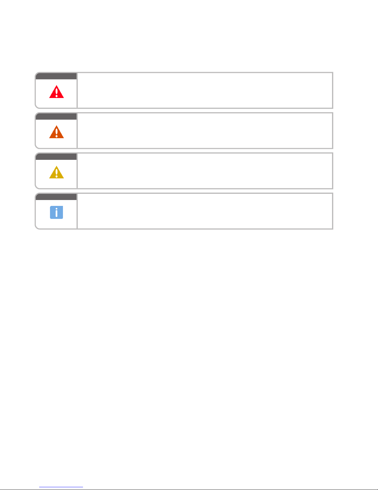
DANGER
In the event of immediate danger.
Consequences: Death, serious or permanent injury!
• Remedial action.
WARNING
In the event of a situation involving potential danger.
Consequences: Death, serious or permanent injury!
• Remedial action.
CAUTION
In the event of a situation involving potential danger.
Consequences: Minor or moderate injuries!
• Remedial action.
NOTICE
In the event of a situation involving potentially adverse effects on the product.
Consequences: Material damage!
• Remedial action.
• Additional product information.
Safety notices
1. This manual with all safety instructions and safety notices must be issued to all personnel involved in operation, maintenance, repair or transportation.
2. The higher level warning notice is used if several hazards apply at the same time. Warnings related to personal injury shall be considered to include a warning of potential damage.
14 | Safety | MW15409/04E 2015-08
TIM-ID: 0000040578 - 004
Page 15
2 Transport
2.1 Transportation
Special tools, Material, Spare parts
Designation / Use Part No. Qty.
Crossbeam
T80092210 1
DANGER
Suspended load
Danger to life
• Never stand under suspended loads!
• Wear appropriate personal protective equipment.
Transportation
1. Install the engine mount locking screws prior to transportation.
2. Use the lifting eyes provided to transport the engine.
3. Use suitable transport and lifting gear only.
4. Transport the engine in the installation position only. Max. admissible diagonal pull 10°.
5. Do not place unsecured parts on the engine.
6. Raise and lower the engine slowly. Do not allow hoist slings or chains to contact the engine or any of its
component parts. Readjust lifting gear as necessary.
7. For special packaging with aluminum foil: Suspend the engine by the lifting eyes on the bearing pedestal or
transport by means of handling equipment (forklift truck) capable of bearing the load.
8. Secure the engine against tilting during transportation. Secure such as to preclude slipping and tipping when
driving up or down inclines and ramps.
Setting down after transport
1. Set the system down on a firm, flat surface only.
2. Make sure that the consistency and load-bearing capacity of the ground or support surface is adequate.
3. Never set the engine down on its oil pan unless expressly authorized to do so by MTU.
MW15409/04E 2015-08 | Transport | 15
TIM-ID: 0000064510 - 001
Page 16
2.2 Lifting requirements
Lifting requirements
DANGER
Suspended load.
Danger to life!
• Use appropriate lifting devices and appliances.
• Never stand beneath a suspended load.
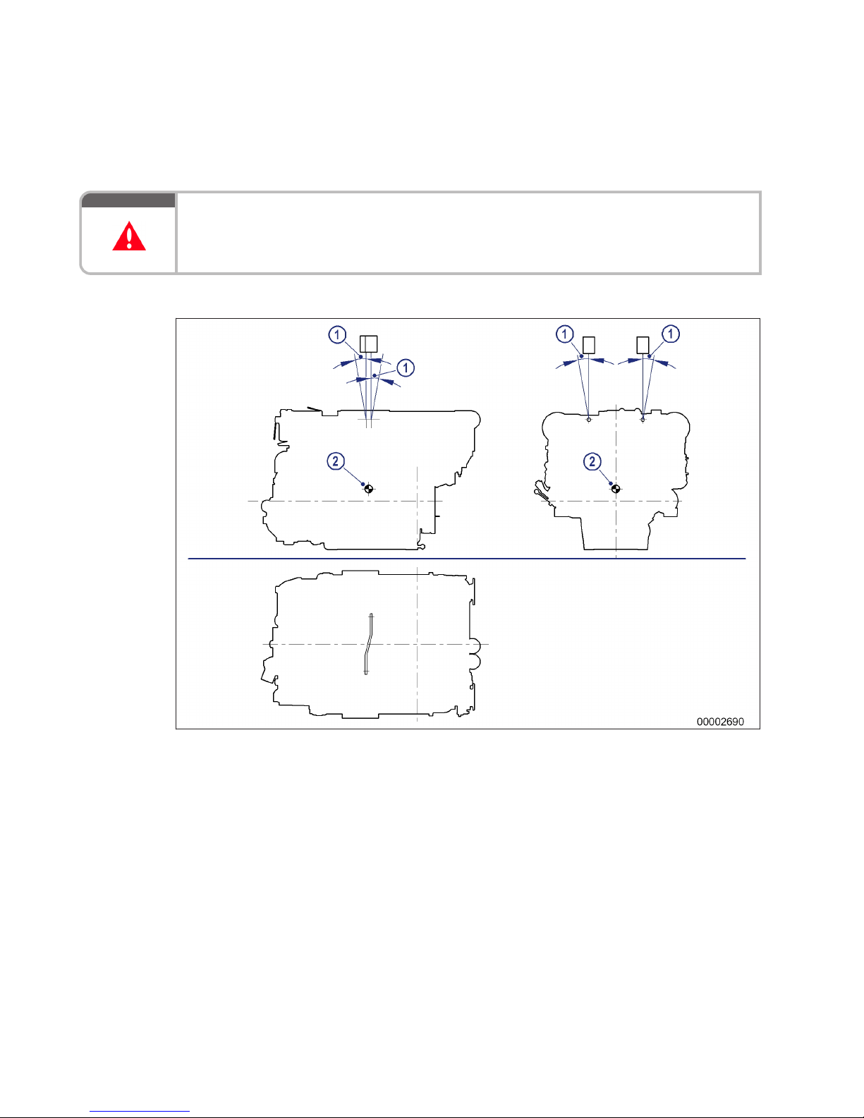
Transportation without flange-mounted gearbox – 8V
1 Max. admissible diagonal
pull 10°
2 Center of gravity
16 | Transport | MW15409/04E 2015-08
TIM-ID: 0000064511 - 001
Page 17
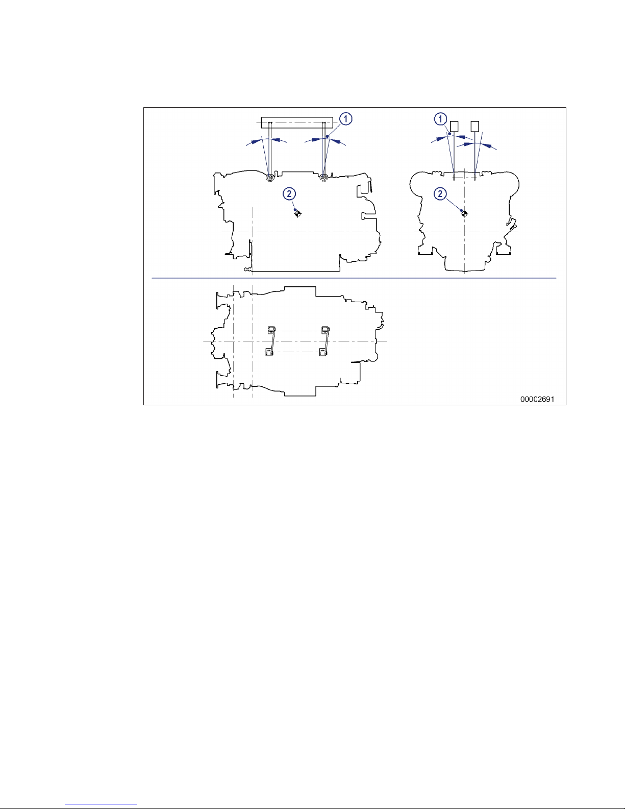
Transportation without flange-mounted gearbox – 12V/16V
1 Max. admissible diagonal
pull 10°
2 Center of gravity
MW15409/04E 2015-08 | Transport | 17
TIM-ID: 0000064511 - 001
Page 18
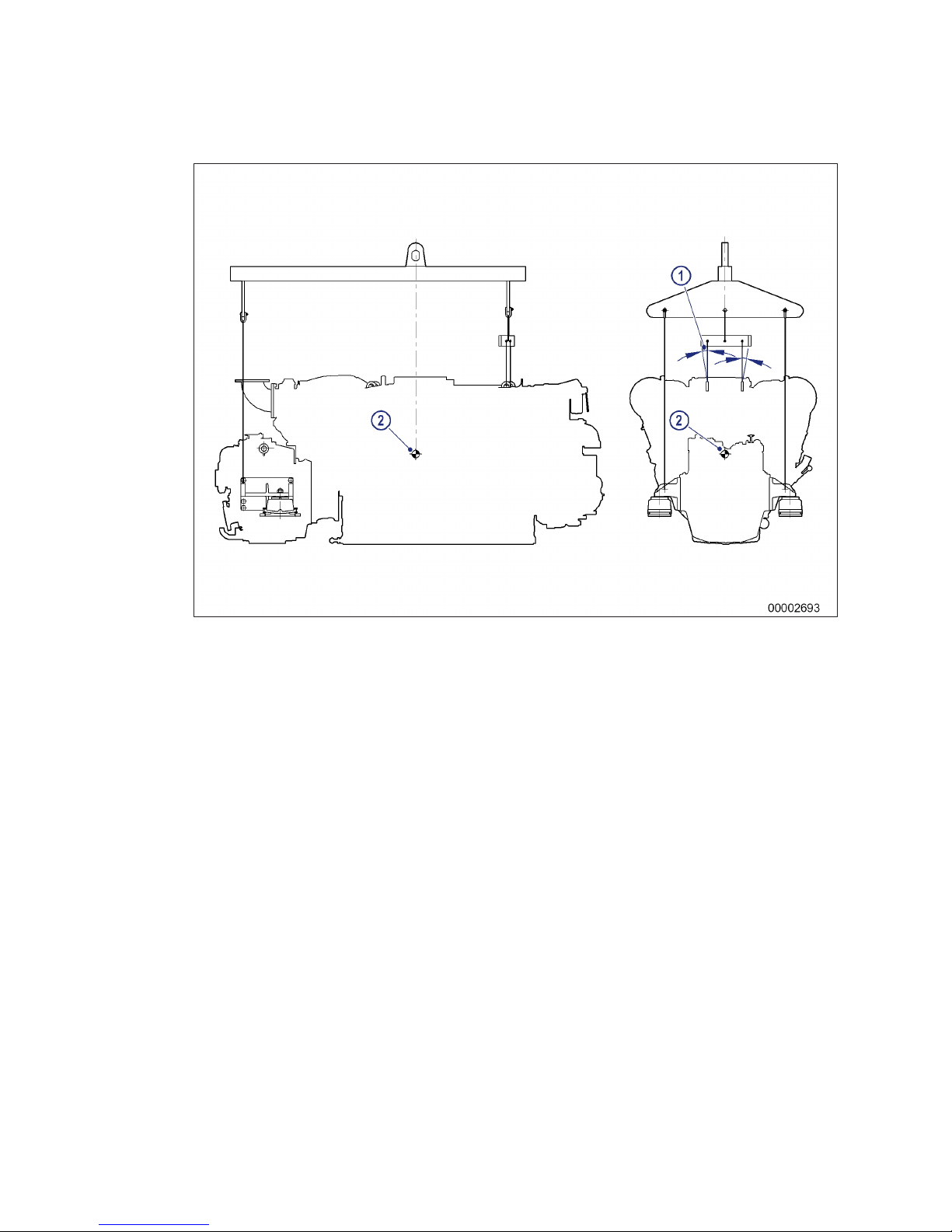
Transportation with flange-mounted gearbox – 8V
1 Max. admissible diagonal
pull 10°
2 Center of gravity
18 | Transport | MW15409/04E 2015-08
TIM-ID: 0000064511 - 001
Page 19
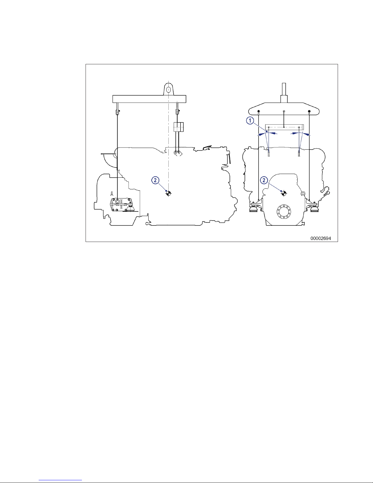
Transportation with flange-mounted gearbox – 12V/16V
1 Max. admissible diagonal
pull 10°
2 Center of gravity
Note engine center of gravity
Refer to the installation/arrangement drawings for details of engine center of gravity.
MW15409/04E 2015-08 | Transport | 19
TIM-ID: 0000064511 - 001
Page 20
3 General Information
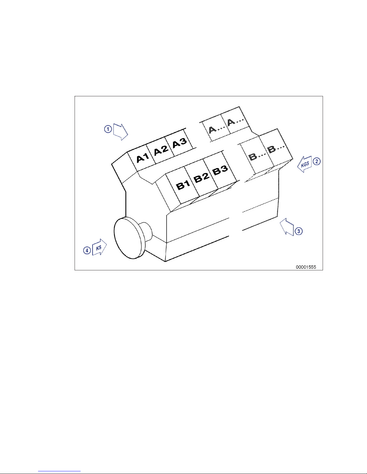
3.1 Engine side and cylinder designations
1 Left engine side (A-side)
2 Engine free end in accord-
ance with DIN ISO 1204
(KGS = Kupplungsgegenseite)
3 Right engine side (B-side)
4 Engine driving end in ac-
cordance with
DIN ISO 1204 (KS = Kupplungsseite)
Engine sides are always designated (in accordance with DIN ISO 1204) as viewed from driving end (4).
For cylinder designation (in accordance with DIN ISO 1204), the letter "Ax" refers to the cylinders on the lefthand side of the engine (1) and letter "Bx" refers to the cylinders on the right-hand side (3). The cylinders of
each bank are numbered consecutively, starting with x=1 at driving end (4).
The numbering of other engine components also starts with 1 at driving end (4).
20 | General Information |
MW15409/04E 2015-08
TIM-ID: 0000002185 - 013
Page 21

3.2 Product description
Description of the engine
Engine
The engine is a liquid-cooled, four-stroke cycle diesel engine, rotating counter-clockwise (seen from driving
end), with direct injection, sequential turbocharging and charge-air cooling.
The engine is monitored by an engine control and monitoring system.
Monitoring in the engine room is carried out by the engine control and monitoring unit.
Fuel system
Electronically controlled unit injection pumps with jacketed HP lines.
The electronic control unit controls
• Beginning of injection
• Injection quantity
Exhaust system
The exhaust system is equipped with triple-walled, water-cooled exhaust lines.
The triple-walled design permits
• Low surface temperature
• Reduced amount of heat to be dissipated by the coolant
• Absolute gas-tightness
Turbocharging
Sequential turbocharging with charge-air cooling (turbochargers can be cut in/out during operation).
Cooling system
Engine cooled by split-circuit cooling system with plate-core heat exchanger.
Service block
The service components are mounted at the auxiliary PTO end.
The arrangement facilitates easy access for maintenance operations.
Service components:
• Raw water pump, coolant pump
• Fuel duplex filter, switchable
• Lube-oil multiple filter, switchable
• Centrifugal lube oil filter
• Coolant expansion tank
Electronic system
Electronic control and monitoring system with integrated safety and test system, providing interfaces to Remote Control System (RCS) and Monitoring and Control System (MCS).
Electronic Engine Control Unit (ECU)
Functions:
• Engine speed control with fuel and speed limitation dependent on engine state and operating conditions;
• Control of sequential turbocharging;
• Data processing logistics for analog and binary signals;
• Interface for data transfer to CAN field bus for remote control and ship-side monitoring;
• RS 232 interface for connection of MTU dialog unit.
MW15409/04E 2015-08
| General Information | 21
TIM-ID: 0000002178 - 006
Page 22
Electronic Engine Monitoring Unit (EMU), optional
Functions:
• Data processing logistics for analog and binary signals;
• Interface for data transfer to CAN field bus for remote control and ship-side monitoring.
Electronic Gear Control Unit (GCU), ship-side wall-mounting
Functions:
• Date processing logistics for gear coupling control;
• Input/output signals as well as data transfer to CAN field bus for remote control and ship-side monitoring.
Monitoring in engine room
Engine control and monitoring unit (LOP)
Functions:
• Alphanumeric, monochrome LCD display for monitoring of measured values as well as alarms when limits
are violated;
• Pushbuttons for menu control and dimming unit;
• Combined control and display elements for local engine/gear control;
• Flashing light and horn for summary alarm in engine room;
• Interface to CAN field bus for connected, communicating monitoring system components.
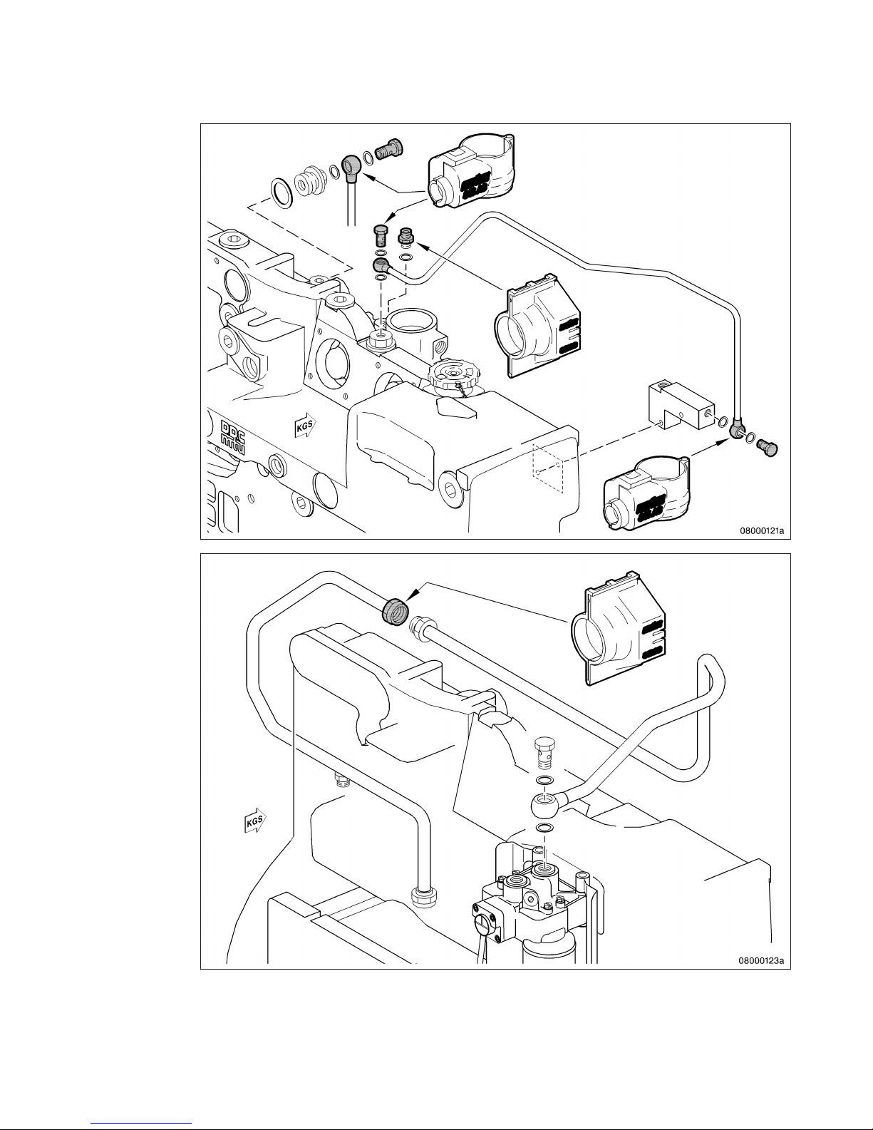
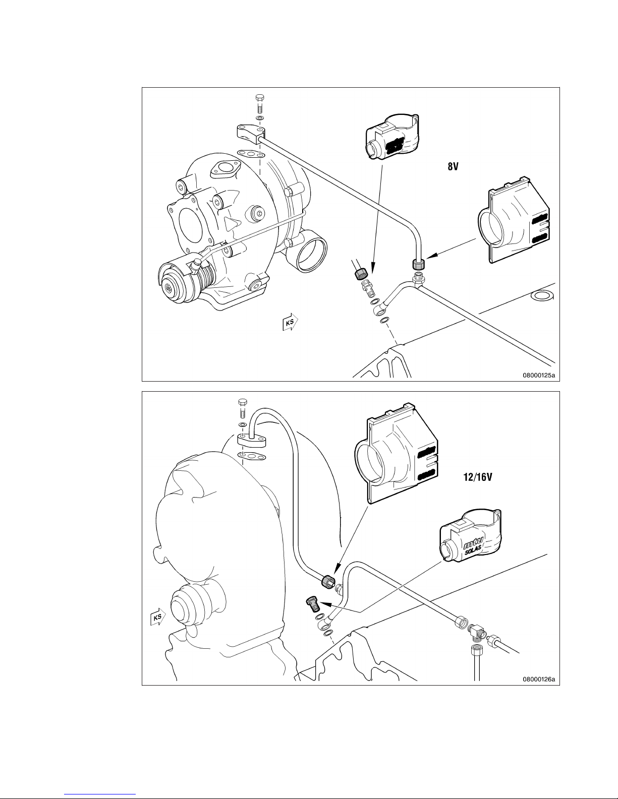
SOLAS – Fire protection specifications
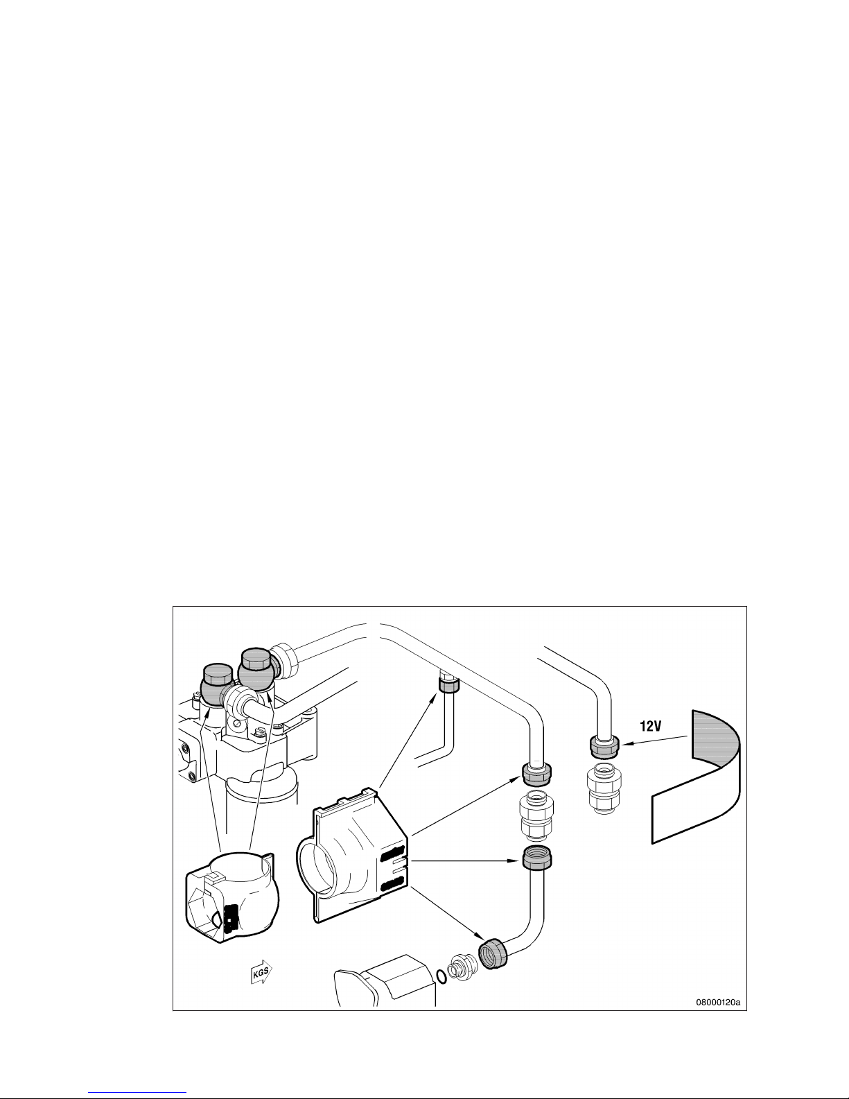
All fuel lines with fuel pressure >1.8 bar are fitted with SOLAS-compliant covers as per MTU standard
MTN5233.
All oil lines with oil pressure >1.8 bar are fitted with SOLAS-compliant covers as per MTU standard
MTN5233.
Fuel system covers
22 | General Information | MW15409/04E 2015-08
TIM-ID: 0000002178 - 006
Page 23
MW15409/04E 2015-08 | General Information | 23
TIM-ID: 0000002178 - 006
Page 24
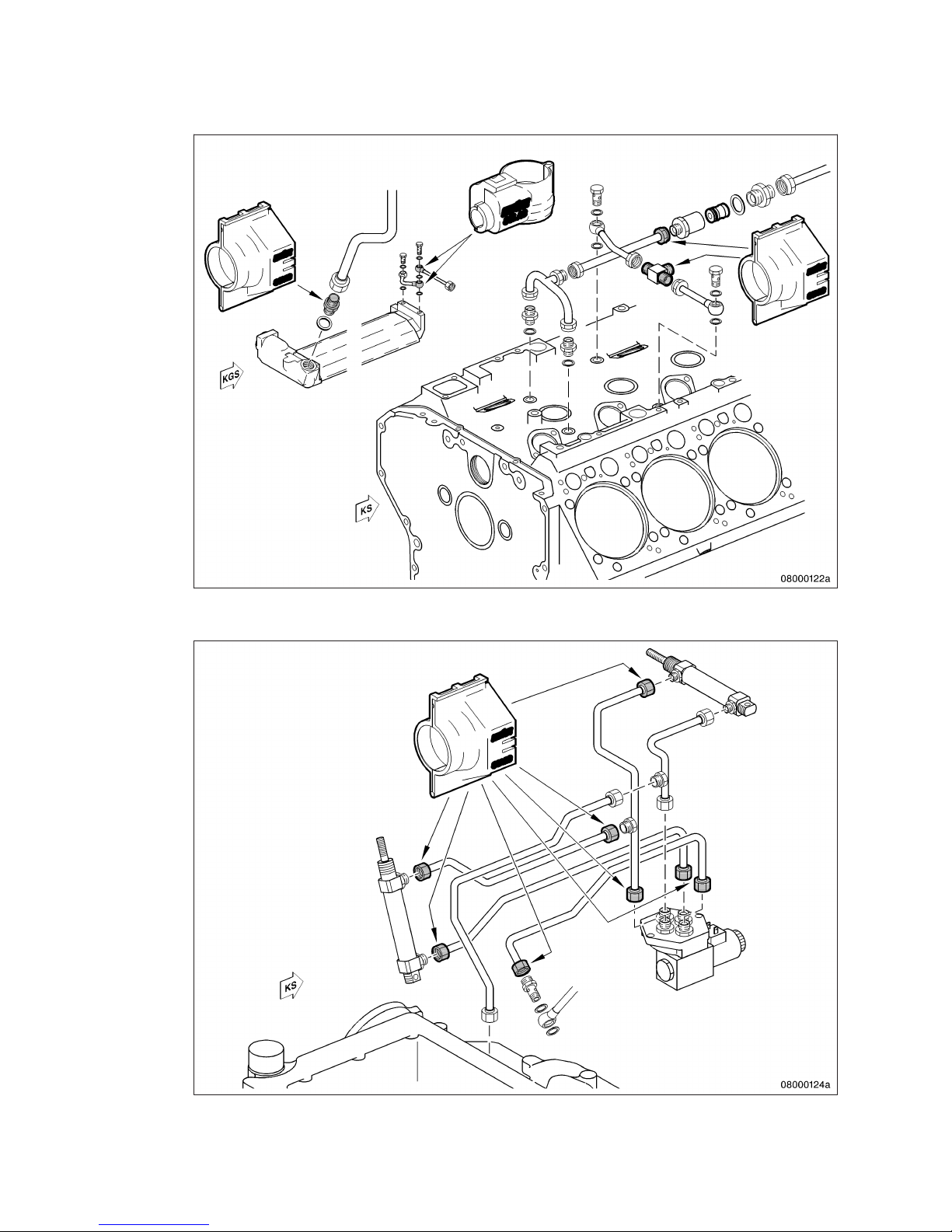
Lube oil system covers
24 | General Information | MW15409/04E 2015-08
TIM-ID: 0000002178 - 006
Page 25
MW15409/04E 2015-08 | General Information | 25
TIM-ID: 0000002178 - 006
Page 26
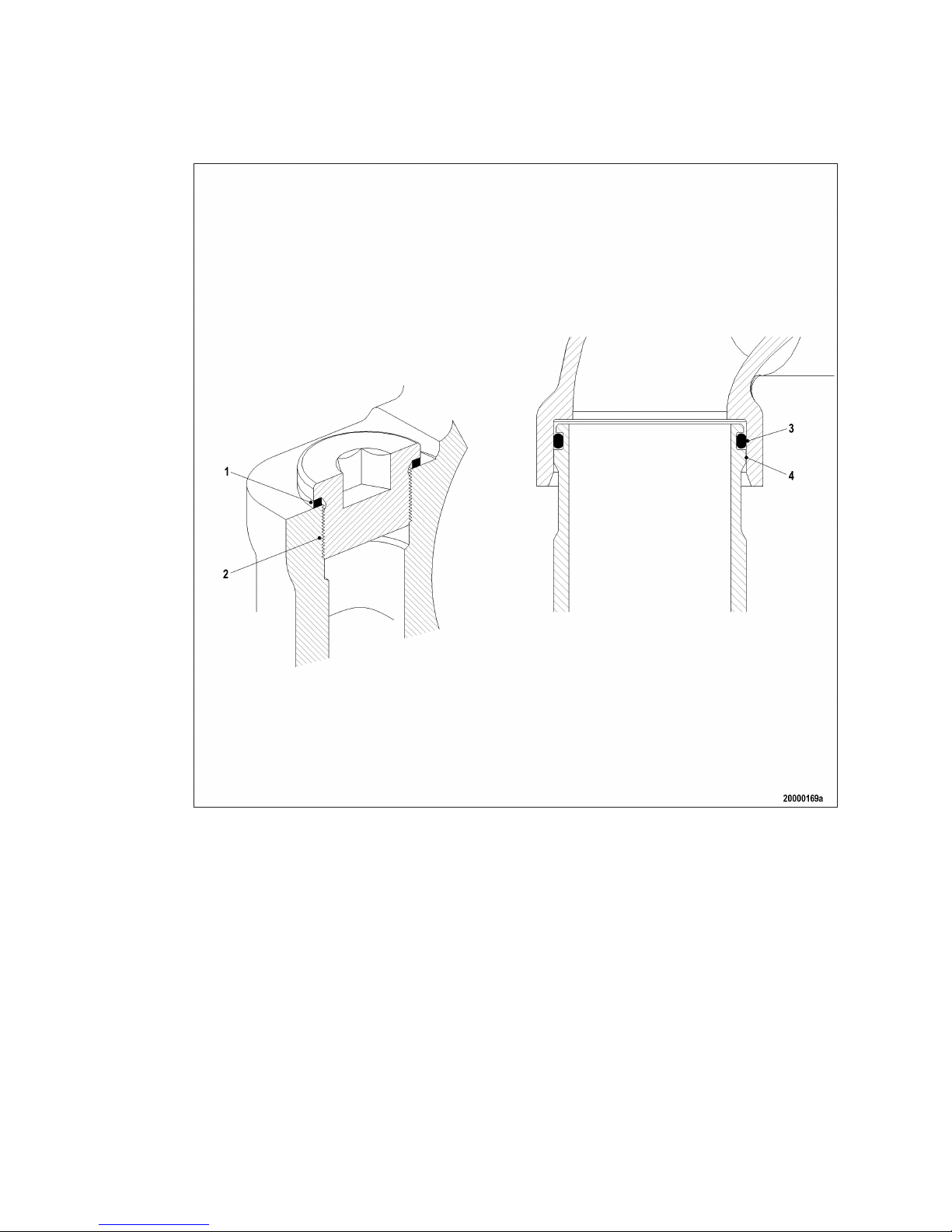
Special unions
The following types of union are spray-proof in case of leakage even without covers and have been confirmed
as being SOLAS-compliant by GL and DNV.
Plug-in pipe union
Design precludes lateral spray as the point of separation is shielded by the sleeve (4).
Only seepage along the pipeline is possible whereby the pressure is greatly reduced by a faulty O-ring (3).
The union is confirmed as being SOLAS-compliant by DNV and GL.
Plugs and sensors
Screw-in plugs (2) are sealed toward the outside either with a copper sealing ring (1), according to DIN, or an
O-ring (ISO).
The fluid must first pass the thread in case of a loose threaded union or faulty sealing ring (2).
The pressure is thus greatly reduced by this and the faulty sealing ring (2) that any leakage is not under pressure.
26 | General Information |
MW15409/04E 2015-08
TIM-ID: 0000002178 - 006
Page 27
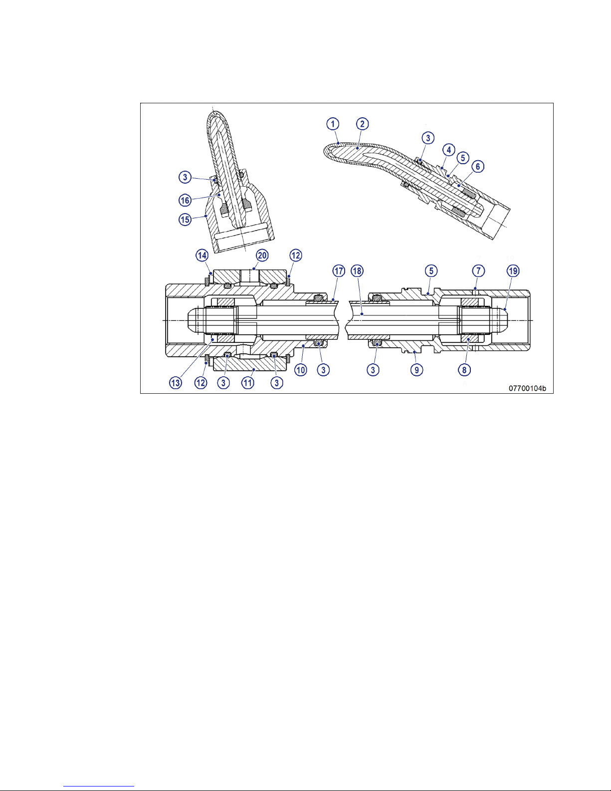
High-pressure unions
1 Jacket pipe
2 HP line
3 O-ring
4 Union nut
5 Recess for O-ring
6 Thrust ring
7 Leakage overflow bore
8 Thrust ring
9 Union nut
10 Union nut
11 Connecting piece
12 Snap ring
13 Thrust ring
14 Compensating disks
15 Union nut
16 Thrust ring
17 External pipe of HP line
18 Internal pipe of HP line
19 Ball-type seal area
20 Leak fuel connection
The HP fuel line is sealed by the thrust ring (8).
In case of leakage around the thrust ring (8) or the HP line (5) fuel escapes into the leakage chamber.
Leak fuel is allowed to escape without pressure via the leakage overflow bore (7). The leakage chamber is
sealed toward the outside by the O-rings (3).
This prevents leaking fuel from escaping.
The union is confirmed as being SOLAS-compliant by DNV and GL.
MW15409/04E 2015-08 | General Information | 27
TIM-ID: 0000002178 - 006
Page 28
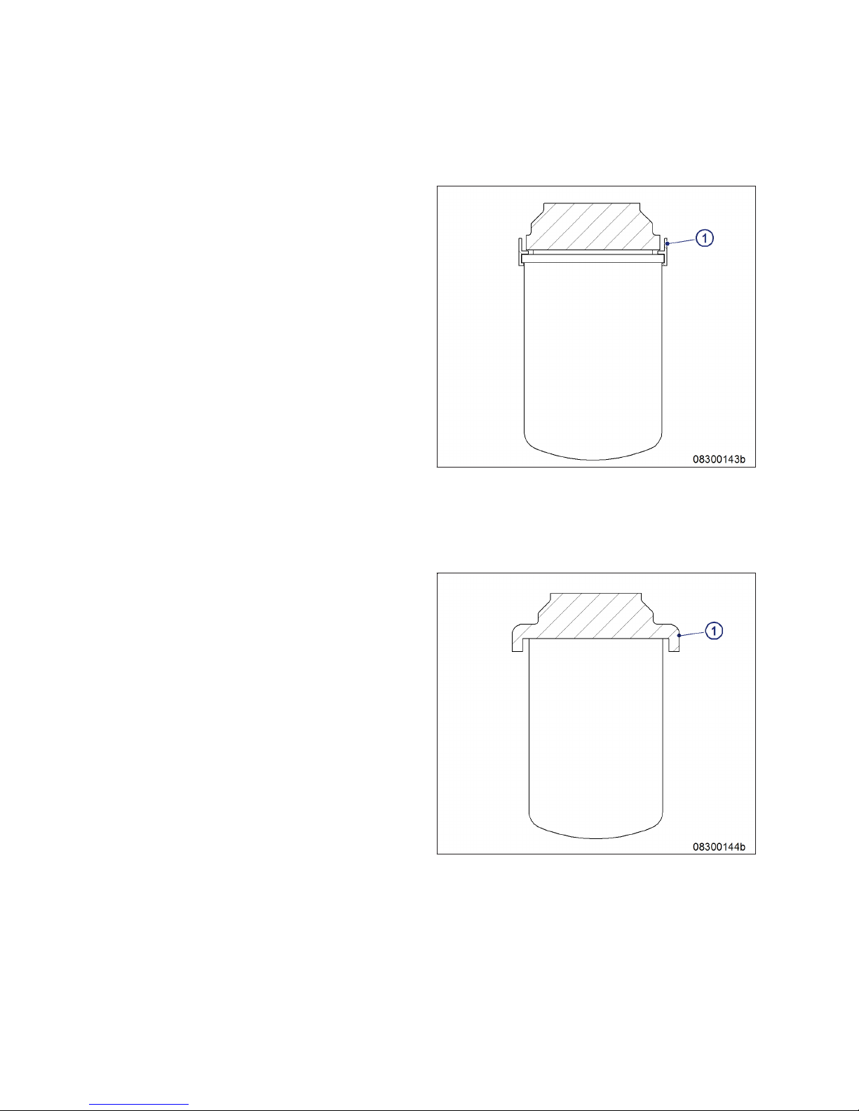
Shielding of fuel filters and lube-oil filters
Shielding with plastic ring
The plastic ring (1) precludes lateral spray.
The fluid is diverted to the catch basin whereby the pressure is greatly reduced.
Shielding by overlapping design
The overlap (1) precludes lateral spray.
The fluid is diverted to the catch basin whereby the pressure is greatly reduced.
28 | General Information |
MW15409/04E 2015-08
TIM-ID: 0000002178 - 006
Page 29
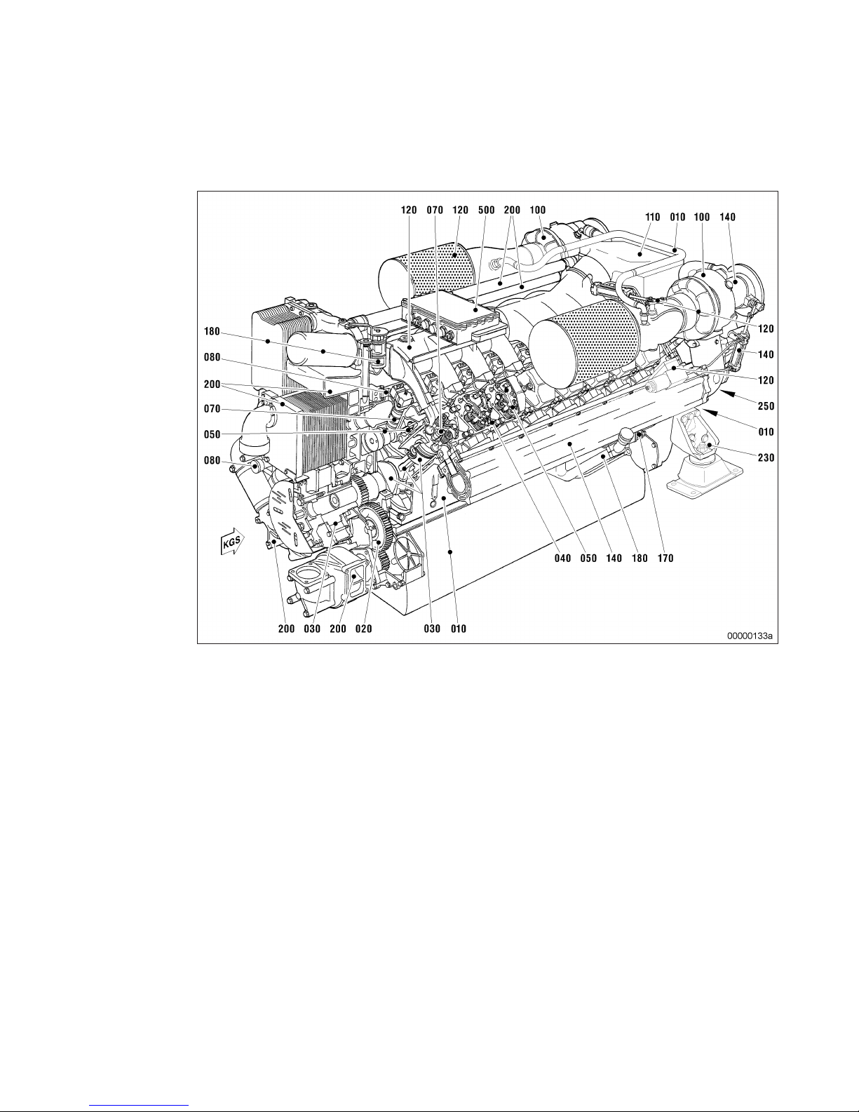
3.3 Engine layout – 2000 M91 engines
Engine layout - functional grouping
010 Crankcase and externally
mounted components
020 Gear train
030 Running gear
040 Cylinder head
050 Valve gear
070 Fuel system (high pressure)
080 Fuel system (low pressure)
100 Exhaust turbocharger
110 Intercooler
120 Air intake / air supply
140 Exhaust system
170 Starting system
180 Lube oil system
200 Cooling system
230 Mounting / support
250 PTO systems, driving end
and free end
500 Monitoring, control and reg-
ulation system
Engine model designation
Key to the engine model designations 12/16V 2000 M91
• 12/16 = Number of cylinders
• V = Cylinder configuration
• 2000 = Series
• M9 = Application segment
• 1 = Design index
MW15409/04E 2015-08
| General Information | 29
TIM-ID: 0000002093 - 001
Page 30
4 Technical Data
4.1 12/16V 2000 M91 engine data
Explanation:
DL Ref. value: Continuous power (CP)
BL Ref. value: Fuel stop power (FSP)
A Design value
G Guaranteed value
R Guideline value
L Limit value, up to which the engine can be operated, without change (e.g. of power setting)
N Not yet defined value
- Not applicable
X Applicable
REFERENCE CONDITIONS
Engine model 12V
2000 M91
16 V
2000 M91
Application group 1DS 1DS
Intake air temperature °C 25 25
Raw water inlet temperature °C 25 25
Barometric pressure mbar 1000 1000
Site altitude above sea level m 100 100
POWER-RELATED DATA (power ratings are net brake power to ISO 3046)
Number of cylinders 12
16
Engine rated speed A rpm 2350 2350
Fuel stop power ISO 3046 A kW 1119 1492
GENERAL CONDITIONS (for maximum power)
Number of cylinders 12
16
Intake air depression (new filter) A mbar 15 15
Intake air depression, max. L mbar 50 50
MODEL-RELATED DATA (basic design)
Number of cylinders 12
16
Cylinder configuration: V angle degrees 90 90
Bore mm 130 130
Stroke mm 150 150
Cylinder displacement liter 1.99 1.99
Total displacement liter 23.88 31.84
Number of inlet valves, per cylinder 2 2
Number of exhaust valves, per cylinder 2 2
30 | Technical Data | MW15409/04E 2015-08
TIM-ID: 0000002886 - 001
Page 31
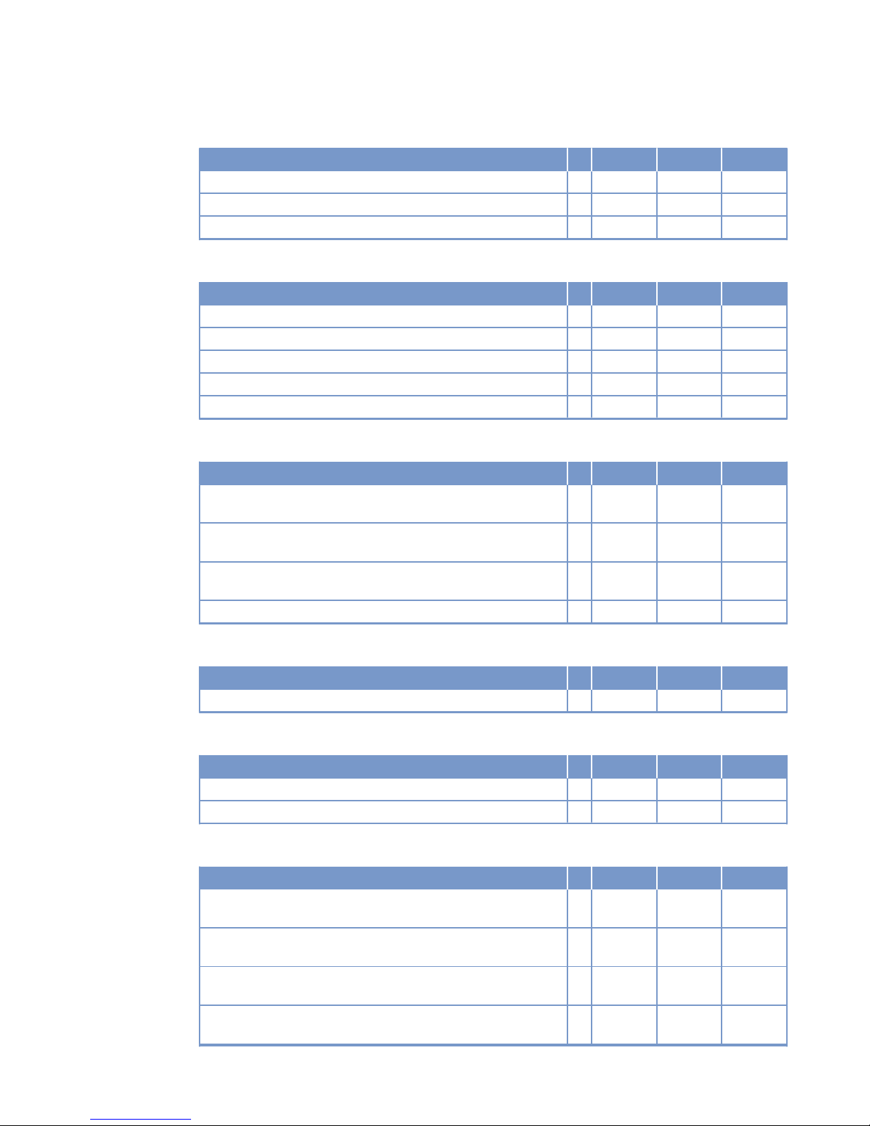
RAW WATER CIRCUIT (open circuit)
Number of cylinders 12
16
Raw water pump inlet pressure, min. L bar -0.4 -0.3
Raw water pump inlet pressure, max. L bar +0.5 +0.5
Pressure loss in external raw water system, max. L bar 0.7 0.7
LUBE OIL SYSTEM
Number of cylinders 12
16
Lube oil temperature before engine, from R °C 83 91
Lube oil temperature before engine, to R °C 88 97
Lube oil operating pressure before engine, from R bar 7.5 6.1
Lube oil operating pressure before engine, to R bar 8.5 7.1
Lube oil operating pressure, low idle (meas. point: before engine) R bar 3.5 3.0
FUEL SYSTEM
Number of cylinders 12
16
Fuel pressure at supply connection on engine, min. (when engine
is starting)
L bar -0.3 -0.3
Fuel pressure at supply connection on engine, min. (when engine
is running)
L bar -0.3 -0.3
Fuel pressure at supply connection on engine, max. (when engine
is starting)
L bar +0.5 +0.5
Fuel supply flow, max. R liter/min 5.1 6.9
STARTING (electric)
Number of cylinders 12
16
Rated starter voltage (standard design) R V= 24 24
STARTING (pneumatic starter)
Number of cylinders 12
16
Starting-air pressure before starter motor, min. R bar 21* 24*
Starting-air pressure before starter motor, max. R bar 30 30
INCLINATIONS, STANDARD OIL SYSTEM (Reference: waterline)
Number of cylinders 12
16
Longitudinal inclination, continuous max., driving end down (Option: max. operating inclinations)
L degrees 15 15
Longitudinal inclination, temporary max., driving end down (Option: max. operating inclinations)
L degrees 22.5 22.5
Longitudinal inclination, continuous max., driving end up (Option:
max. operating inclinations)
L degrees 5 0
Longitudinal inclination, temporary max., driving end up (Option:
max. operating inclinations)
L degrees 10 6
MW15409/04E 2015-08 | Technical Data | 31
TIM-ID: 0000002886 - 001
Page 32
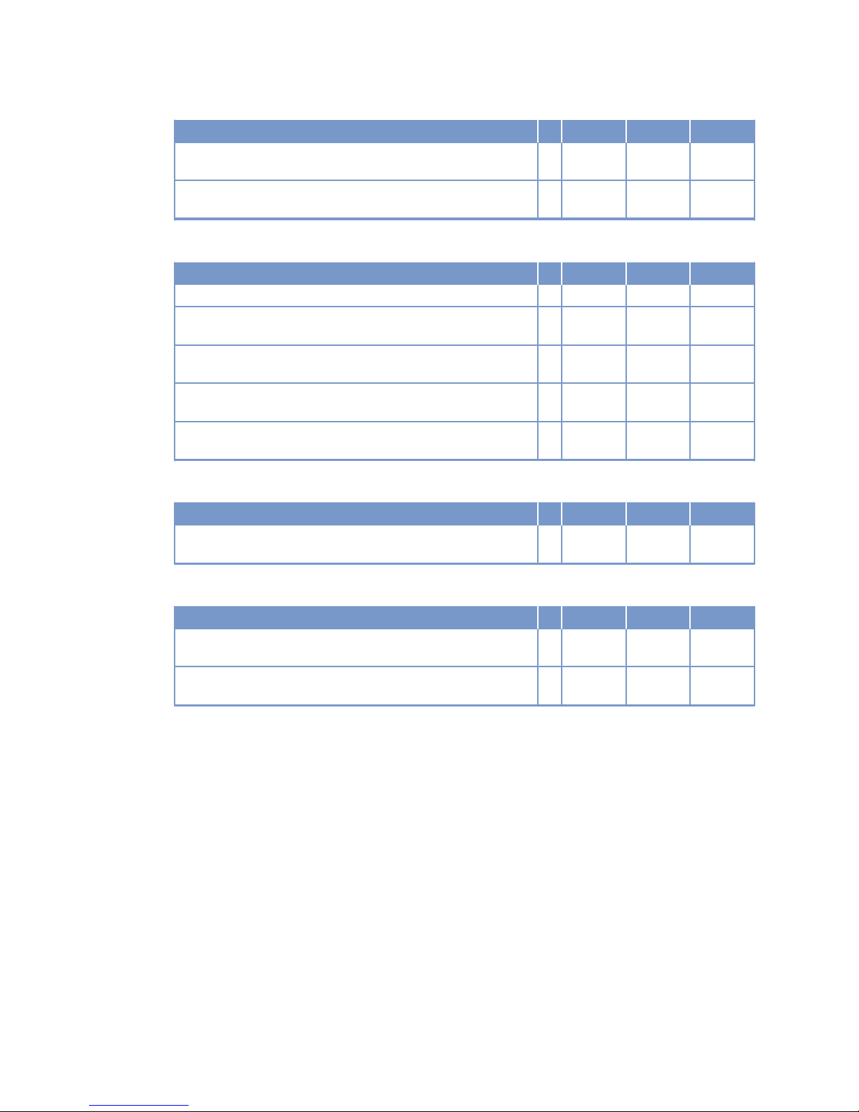
Number of cylinders 12
16
Transverse inclination, continuous max. (Option: max. operating
inclinations)
L degrees 22.5 22.5
Transverse inclination, temporary max. (Option: max. operating inclinations)
L degrees 40 35
CAPACITIES
Number of cylinders 12
16
Engine coolant capacity (with cooling equipment) R liter 110 160
Engine oil capacity, initial filling (standard oil system) (Option:
max. operating inclinations)
R liter 105 134
Oil change quantity, max. (standard oil system) (Option: max. operating inclinations)
R liter 98 127
Oil pan capacity, dipstick mark min. (standard oil system) (Option:
max. operating inclinations)
L liter 73 97
Oil pan capacity, dipstick mark max. (standard oil system) (Option:
max. operating inclinations)
L liter 88 117
WEIGHTS / MAIN DIMENSIONS
Number of cylinders 12
16
Engine dry weight (with attached standard accessories, without
coupling)
R kg 2600 3200
ACOUSTICS
Number of cylinders 12
16
Exhaust noise, unsilenced - FSP (free-field sound-pressure level
Lp, 1m distance, ISO 6798)
R db(A) 107 112
Engine surface noise with attenuated intake noise (filter) - FSP
(free-field sound pressure level Lp, 1m distance, ISO 6798)
R db(A) 106 110
32 | Technical Data | MW15409/04E 2015-08
TIM-ID: 0000002886 - 001
Page 33

4.2 Firing order
Number of cylinders
Firing order
8 V A1-B4-A4-A2-B3-A3-B2-B1
12 V A1-B2-A5-B4-A3-B1-A6-B5-A2-B3-A4-B6
16 V A1-B5-A3-A5-B2-B8-A2-A8-B3-A7-B4-B6-A4-A6-B1-B7
MW15409/04E 2015-08 | Technical Data | 33
TIM-ID: 0000002802 - 004
Page 34
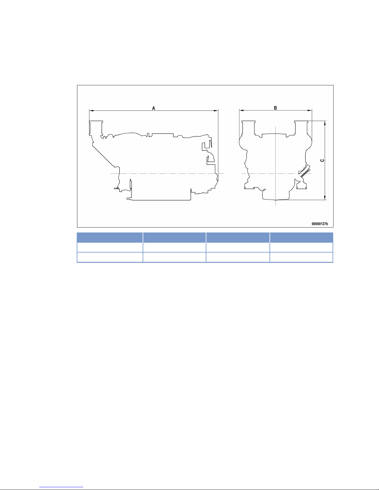
4.3 Main engine dimensions
Main engine dimensions
Engine model Overall length (A) Overall width (B)
Overall height (C)
12V 2000 M91 approx. 2470 mm approx. 1400 mm approx. 1460 mm
16V 2000 M91 approx. 2815 mm approx. 1400 mm approx. 1520 mm
34 | Technical Data | MW15409/04E 2015-08
TIM-ID: 0000002156 - 001
Page 35
5 Operation
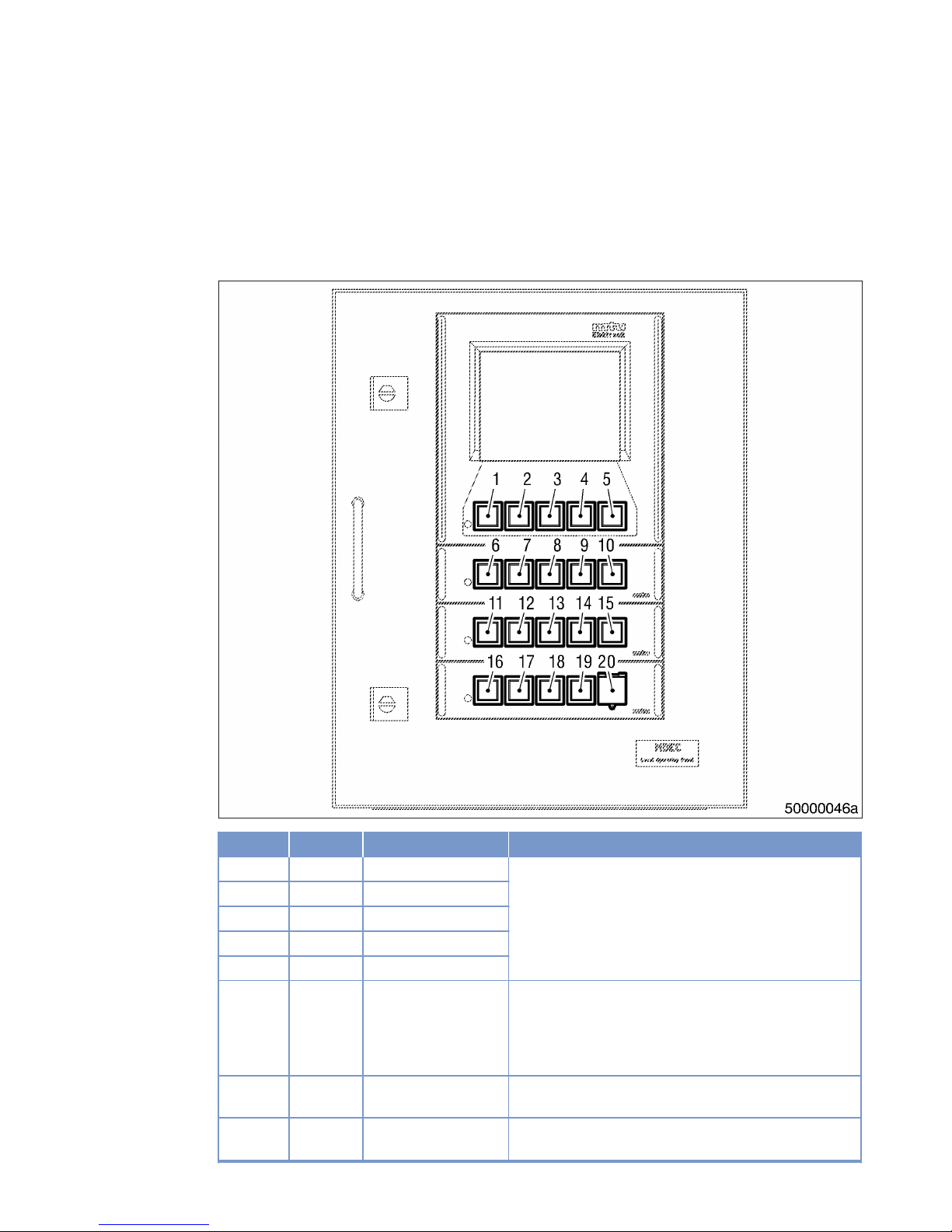
5.1 LOP controls (without Blue Line automation system)
LOP – Controls
Item Color Inscription
Meaning / Function
1 White F1 Function keys to control the man-machine interface.
Functions vary and are displayed on the LCD screen.
2 White F2
3 White F3
4 White F4
5 White F5
6 White ALARM ACKNOWL Pressing the button the first time stops alarm signaliza-
tion.
Pressing the button a second time acknowledges an active alarm.
LED (spot) lights up when an alarm is active.
7 White DIM ↑ Holding down the button increases LCD background illu-
mination.
8 White DIM ↓ Holding down the button decreases LCD background illu-
mination.
MW15409/04E 2015-08 | Operation | 35
TIM-ID: 0000008860 - 004
Page 36

Item Color Inscription
Meaning / Function
9 White LAMP TEST Pressing the button initiates lamp test.
10 Red TEST OVERSPEED Pressing the button initiates overspeed test.
LED (spot) lights up as long as the overspeed test is running.
11 Green (depending on type of
gearbox and propulsion)
FPP: Pressing the button engages gear ahead.
CPP, WJ, VS: Pressing the button engages clutch.
LED (spot) lights up when GCU feedback is active.
12 Green FPP, CPP, WJ, VS: Pressing the button disengages clutch.
LED (spot) lights up when GCU feedback is active.
13 Green FPP: Pressing the button engages gear astern.
CPP, VS: No function assigned.
WJ: Holding down the button provides flushing of water jet
intake channel (water-jet reverse) .
LED (spot) lights up when GCU feedback is active.
14 White ENGINE SPEED IN-
CREASE
Engine speed is increased as long as the button is held
down.
15 White ENGINE SPEED DE-
CREASE
Engine speed is decreased as long as the button is held
down.
16 Green READY FOR OPERA-
TION
Pressing the button causes changeover between “Not
ready for operation” and “Ready for operation” status.
LED (spot) lights up at "Ready for operation" position.
17 Green LOCAL OPERATION Pressing the button activates changeover between local
and remote control mode.
LED (spot) lights up when local mode is active.
18 White START Pressing the button initiates the automatic engine start
sequence.
LED (spot) lights up as long as the starting procedure is
running.
19 White STOP Pressing the button initiates automatic engine stopping
procedure.
LED (spot) lights up as long as the STOP signal is available
(also if transmitted from RCS).
20 Red EMERGENCY STOP Pressing the button initiates an immediate emergency en-
gine stop.
LED (spot) flashes once the emergency stop has been
tripped and until the alarm has been acknowledged.
36 | Operation | MW15409/04E 2015-08
TIM-ID: 0000008860 - 004
Page 37

5.2 Putting the engine into operation after extended out-of-service
periods (>3 months)
Preconditions
☑ Engine is stopped and starting disabled.
☑ MTU Preservation and Represervation Specifications (A001070/..) are available.
Putting the engine into operation (out-of-service period > 3 months)
Item Measure
Engine Depreserve (→ MTU Preservation and Represervation Specifications
A001070/..).
Universal shaft Lubricate (→ Page 142).
Lube oil system Check engine oil level (→ Page 116).
Fuel prefilter Fill with fuel (→ Page 97).
Fuel prefilter, pressure
gauge
Align adjustable pointer with position of pressure indicator (→ Page 92).
Fuel system Vent (→ Page 88).
Raw-water pump (if located
above waterline)
Prime with water (approx. 3 4 l) (→ Page 135).
Coolant circuit If engine is out of service for more than one year, change engine coolant
(→ Page 130).
Coolant circuit Check coolant level (→ Page 129).
Coolant circuit Heat engine coolant with coolant preheating unit.
Engine governor ECU Check plug-in connections (→ Page 147).
Engine control system Switch master switch to ON;
Press illuminated pushbutton READY FOR OPERATION (→ Page 35).
LOP Press illuminated pushbutton LAMP TEST (→ Page 35).
MW15409/04E 2015-08 | Operation | 37
TIM-ID: 0000002215 - 004
Page 38

5.3 Putting the engine into operation after scheduled out-ofservice period
Preconditions
☑ Engine is stopped and starting disabled.
Putting into operation
Item Action
Lube oil system Check engine oil level (→ Page 116).
Coolant circuit Check coolant level (→ Page 129).
Coolant circuit Preheat coolant with preheating unit.
Fuel prefilter Drain water (→ Page 93).
Battery-charging generator
drive
Check condition of drive belt (→ Page 137)
Engine Control System Switch master switch to ON;
Press illuminated pushbutton READY FOR OPERATION (→ Page 35).
LOP Press illuminated pushbutton LAMP TEST (→ Page 35).
38 | Operation | MW15409/04E 2015-08
TIM-ID: 0000002684 - 004
Page 39
5.4 Engine start at LOP (without BlueLine automation system)
Preconditions
☑ Gearbox is in neutral position.
☑ External start interlock is not activated.
☑ Emergency air-shutoff flaps (if applicable) are open.
DANGER
Rotating and moving engine parts.
Risk of crushing, danger of parts of the body being caught or pulled in!
• Before cranking the engine with starter system, make sure that there are no persons in the engine's
danger zone.
WARNING
High level of engine noise when the engine is running.
Risk of damage to hearing!
• Wear ear protectors.
Cranking the engine (out-of-service period > 1 month)
Item Action
Engine Crank on starter (→ Page 65).
Starting the engine from LOP
Item Action
Engine Start in unloaded condition.
System Switch on.
LOP:
• Illuminated switch LOCAL OPERATION lights up brightly (local control
mode is active) (→ Page 35);
• Illuminated pushbutton GEARBOX NEUTRAL lights up brightly (gearbox is
disengaged) (→ Page 35).
LOP Press illuminated switch READY FOR OPERATION briefly (→ Page 35).
• Illuminated switch READY FOR OPERATION lights up brightly.
LOP Press illuminated pushbutton START briefly (→ Page 35).
• Illuminated pushbutton START of the relevant engine lights up brightly;
• Automatic starting sequence is performed;
• Engine speed display instrument indicates increasing speed;
• After completion of the starting sequence, the engine runs at idle speed,
and the illuminated pushbutton START changes to basic brightness.
MW15409/04E 2015-08 | Operation | 39
TIM-ID: 0000002241 - 004
Page 40
5.5 Starting the engine at the BlueLine automation system
(control stand)
DANGER
Rotating and moving engine parts.
Risk of crushing, danger of parts of the body being caught or pulled in!
• Before cranking the engine with starter system, make sure that there are no persons in the engine's
danger zone.
WARNING
High level of engine noise when the engine is running.
Risk of damage to hearing!
• Wear ear protectors.
Cranking the engine (out-of-service period > 1 month)
Item Action
Engine Crank on starting system (→ Page 65).
Starting the engine at the BlueLine automation system (control stand)
Item Action
Engine Start at BlueLine automation system (control stand) (→ BlueLine documenta-
tion).
40 | Operation | MW15409/04E 2015-08
TIM-ID: 0000002698 - 005
Page 41
5.6 Engine emergency stop at BlueLine automation system
(control stand)
NOTICE
An emergency stop causes extreme stress to the engine plant.
Risk of overheating, damage to components!
• Initiate emergency stop only in emergency situations.
Engine emergency stop at BlueLine automation system
Item Measure
Engine Emergency stop at BlueLine automation system (→ Operating Instructions for
BlueLine).
MW15409/04E 2015-08 | Operation | 41
TIM-ID: 0000002704 - 005
Page 42
5.7 Operational checks
DANGER
Rotating and moving engine parts.
Risk of crushing, danger of parts of the body being caught or pulled in!
• Only run the engine at low power. Keep away from the engine's danger zone.
WARNING
High level of engine noise when the engine is running.
Risk of damage to hearing!
• Wear ear protectors.
Operational checks
Item Measure
Engine under load
Engine at nominal speed
Visually inspect engine for leaks and general condition;
Check for abnormal running noises and vibration;
Check exhaust color (→ Page 52).
Fuel prefilter Check if suction-side pressure indicated at the fuel prefilter is within the limit
(→ Page 92).
Drain water and contaminants (→ Page 93).
Air filter Check signal ring position of contamination indicator (→ Page 112).
Replace air filter (→ Page 110), if the signal ring is completely visible in the
service indicator observation window.
HT coolant pump Check relief bore for oil and coolant discharge and contamination
(→ Page 133).
Raw water pump Check relief bore for oil and water discharge and contamination
(→ Page 136).
Intercooler Check condensate drain (if applicable) (→ Page 109).
Engine oil Check engine oil level (→ Page 116).
42 | Operation | MW15409/04E 2015-08
TIM-ID: 0000002274 - 007
Page 43
5.8 Coupling – Engaging from LOP
Preconditions
☑ LOCAL OPERATION illuminated pushbutton lights up brightly (local operating mode is active).
☑ Engine speed in engagement window.
☑ No external engagement interlock active.
DANGER
Vessel is sailing blind.
In Local Operation mode, the propulsion plant is controlled from the engine room.
Risk of accidents!
• Only execute vessel movements on the instructions of a person who has visual contact with the area
outside the vessel.
Engaging coupling without reversing gearbox (CPP, WJ, VS)
Item Measure
LOP Press COUPLING IN illuminated pushbutton (→ Page 35).
• COUPLING IN button flashes.
• Coupling is engaged.
• After receiving the feedback signal from coupling, the COUPLING IN button is illuminated brightly.
Engaging coupling in ahead direction with reversing gearbox (FPP, WJ)
Item Measure
LOP Press COUPLING AHEAD illuminated pushbutton (→ Page 35).
• COUPLING AHEAD button flashes.
• Gearbox is engaged in AHEAD direction.
• After receiving the feedback signal from coupling, the COUPLING AHEAD
button is illuminated brightly.
Engaging coupling in astern direction with reversing gearbox (FPP)
Item Measure
LOP Press COUPLING ASTERN illuminated pushbutton (→ Page 35).
• COUPLING ASTERN button flashes.
• Gearbox is engaged astern.
• After receiving the feedback signal from coupling, the COUPLING ASTERN
button is illuminated brightly.
MW15409/04E 2015-08 | Operation | 43
TIM-ID: 0000002700 - 004
Page 44

5.9 Coupling – Disengaging from LOP
Preconditions
☑ LOCAL OPERATION illuminated pushbutton lights up brightly (local operating mode is active).
☑ Engine speed in disengagement window.
Disengaging coupling without reversing gearbox (CPP, WJ, VS)
Item Measure
LOP Press COUPLING OUT illuminated pushbutton (→ Page 35).
• COUPLING OUT button flashes.
• Coupling is disengaged.
• After receiving the feedback signal from coupling, the COUPLING OUT button is illuminated brightly.
Disengaging coupling with reversing gearbox (FPP, WJ)
Item Measure
LOP Press COUPLING NEUTRAL illuminated pushbutton (→ Page 35).
• COUPLING NEUTRAL button flashes.
• Gearbox is disengaged (neutral position).
• After receiving the feedback signal from coupling, the COUPLING NEUTRAL button is illuminated brightly.
44 | Operation | MW15409/04E 2015-08
TIM-ID: 0000002810 - 004
Page 45
5.10 Waterjet – Flushing from LOP (optional)
Preconditions
☑ LOCAL OPERATION illuminated pushbutton is lit brightly (local operating mode is active).
☑ Vessel is at a standstill and waterjet bucket is below the waterline.
☑ Engine speed is in engagement window.
☑ No external engagement interlock is active.
NOTICE
Waterjet flushing puts excessive strain on the bearings.
Bearing damage!
• Do not flush waterjet for too long.
• Follow instructions of the waterjet manufacturer.
Flushing with reversing gearbox and flushing mode
Item Measure
LOP Press FLUSH illuminated pushbutton and keep pressed (→ Page 35).
• FLUSH pushbutton flashes.
• Gearbox is engaged astern.
• After receiving the feedback signal from coupling, the FLUSH pushbutton
is illuminated brightly.
LOP Release FLUSH illuminated pushbutton.
• FLUSH pushbutton flashes.
• Gearbox is disengaged (neutral position).
• Illumination of FLUSH pushbutton is switched off as soon as the feedback
signal from coupling is received.
MW15409/04E 2015-08 | Operation | 45
TIM-ID: 0000002330 - 006
Page 46
5.11 Engine shutdown at LOP (without BlueLine automation
system)
Preconditions
☑ Engine is running in Local mode
NOTICE
Stopping the engine when it is running at full load causes extreme stress to the engine.
Risk of overheating, damage to components!
• Before shutting down, disengage gear and run the engine at idle speed for at least 10 minutes until
engine temperatures have dropped and constant values are displayed.
Stopping the engine from LOP
Item Action
LOP Disengage gearbox (→ Page 35).
LOP Operate engine at idle speed (→ Page 35).
Temperature indications Wait until engine temperatures do not fall any further.
LOP Press illuminated pushbutton STOP (→ Page 35).
• Illuminated pushbutton STOP lights up.
• Engine at a standstill.
46 | Operation | MW15409/04E 2015-08
TIM-ID: 0000002299 - 005
Page 47
5.12 Stopping the engine at the BlueLine automation system
(control stand)
NOTICE
Stopping the engine when it is running at full load causes extreme stress to the engine.
Risk of overheating, damage to components!
• Before shutting down, disengage gear and run the engine at idle speed for at least 10 minutes until
engine temperatures have dropped and constant values are displayed.
Stopping the engine at the BlueLine automation system (control stand)
Item Measure
Engine Stop the engine at the BlueLine automation system (control stand) (→ Blue-
Line Operating Instructions).
MW15409/04E 2015-08 | Operation | 47
TIM-ID: 0000002702 - 005
Page 48
5.13 Emergency engine shutdown at LOP (without BlueLine
automation system)
NOTICE
An emergency stop causes extreme stress to the engine plant.
Risk of overheating, damage to components!
• Initiate emergency stop only in emergency situations.
Emergency engine shutdown from LOP
Item Action
LOP Open cap of illuminated pushbutton EMERGENCY STOP (→ Page 35).
LOP Press illuminated pushbutton EMERGENCY STOP.
• Engine is stopped by disconnecting the power supply to the ECU;
• On engines with emergency air-shutoff flaps: flaps close;
• Illuminated pushbutton EMERGENCY STOP flashes. Horn, flashing lamp
etc. are tripped.
After emergency engine shutdown from LOP
Item Action
LOP Press illuminated pushbutton ALARM ACKNOWLEDGE (→ Page 35).
• Audible and visual alarm signaling stops.
LOP Press illuminated pushbutton ALARM ACKNOWLEDGE again.
• Power supply to ECU is provided;
• Alarm has been acknowledged.
Engine On engines with emergency air-shutoff flaps: open flaps.
• Engine is ready for starting.
48 | Operation | MW15409/04E 2015-08
TIM-ID: 0000002313 - 004
Page 49
5.14 After stopping the engine
Preconditions
☑ MTU Fluids and Lubricants Specifications (A001061/..) are available.
NOTICE
Engine coolant with inadequate freeze protection. Water remaining in the pressure sensors freezes at
temperatures below 0 °C.
Risk of sensor damage!
• Remove pressure sensors and shake off residual water.
After stopping the engine
Item Measure
Coolant circuit Drain coolant (→ Page 131) if:
• freezing temperatures are expected and the engine is to remain out of
service for an extended period, but engine coolant has no antifreeze additive;
• the engine room is not heated;
• the coolant is not kept at a suitable temperature;
• the antifreeze concentration is insufficient for the engine-room temperature;
• antifreeze concentration is 50 % and engine-room temperature is below
-40 °C.
Raw water Drain
• if freezing temperatures are to be expected and the engine is to remain
out of service for an extended period.
Engine Control System Switch off.
Air intake and exhaust system
Out-of-service-period > 1 week
• Seal engine's air and exhaust sides.
Engine Out-of-service-period > 1 month
• Carry out engine preservation (→ MTU Preservation and Represervation
Specifications A001070/..)
MW15409/04E 2015-08 | Operation | 49
TIM-ID: 0000002324 - 009
Page 50
5.15 Plant – Cleaning
Preconditions
☑ Engine is stopped and starting disabled.
☑ No operating voltage is applied.
Special tools, Material, Spare parts
Designation / Use Part No. Qty.
High-pressure cleaning unit
- 1
Cleaner (Hakupur 50/136)
X00056700 1
WARNING
Compressed air gun ejects a jet of pressurized air.
Risk of injury to eyes and damage to hearing, risk of rupturing internal organs!
• Never direct air jet at people.
• Always wear safety goggles/face mask and ear defenders.
WARNING
Water jet from high-pressure cleaning unit.
Risk of eye injury, risk of scalding!
• Do not direct water jet at persons.
• Wear protective clothing, protective gloves, and goggles/safety mask.
NOTICE
Cleaning agents should not be left to take effect for too long.
Damage to components is possible!
• Observe manufacturer's instructions.
NOTICE
Blowing down product with compressed air.
Entry of dirt and damage to components is possible!
• Do not aim compressed air gun directly at seals or electronic components such as connectors or
ECUs.
Plant – Cleaning
1. Carry out plant cleaning only in areas where an appropriate oil separator is provided (environmental protection).
2. Prior to putting the cleaning unit into operation, read the operating instructions of the high-pressure cleaning
units carefully and observe the safety precautions.
3. The following requirements apply for cleaning the plant outside with a high-pressure cleaning unit:
• The pressure of the high-pressure jet (cleaning jet) must not exceed 50 bar.
• A minimum distance between spray nozzle and plant of 1 m must be observed.
• The temperature of the cleaning medium must not exceed 80 °C.
4. For external cleaning with high-pressure jet, use a flat-mouth nozzle only.
Note: Never direct compressed air directly at electronic components.
5. Carry out external cleaning as follows:
a) Seal all openings in a suitable way.
b) Remove coarse dirt.
c) Spray on cleaner sparingly and leave it for 1 to 5 minutes.
d) Use the high-pressure jet to remove the loosened dirt.
e) Dry engine with compressed air.
50 | Operation |
MW15409/04E 2015-08
TIM-ID: 0000010171 - 032
Page 51

6 Maintenance
6.1 Maintenance task reference table [QL1]
The maintenance tasks and intervals for this product are defined in the Maintenance Schedule. The Maintenance Schedule is a stand-alone publication.
The task numbers in this table provide reference to the maintenance tasks specified in the Maintenance
Schedule.
Task Maintenance tasks
W0500 Check engine oil level (→ Page 116)
W0501 Visually inspect engine for leaks and general condition (→ Page 42)
W0502 Check intercooler drain (if fitted) (→ Page 42)
W0503 Check signal ring position of service indicator on air filter (→ Page 42)
W0505 Check relief bores of coolant pump(s) (→ Page 42)
W0506 Check engine for abnormal running noises, exhaust color and
vibrations
(→ Page 42)
W0507 Drain water and contaminants from fuel prefilter (if fitted) (→ Page 42)
W0508 Check reading on differential pressure gauge of fuel prefilter (if
fitted)
(→ Page 42)
W1001 Replace fuel filter or fuel filter element (→ Page 90)
W1002 Check valve clearance (→ Page 73)
W1003 Check belt condition and tension, replace if necessary (→ Page 137)
W1005 Replace air filter (→ Page 110)
W1006 Replace fuel injectors (→ Page 81)
W1007 Replace fuel injection pump(s) (→ Page 77)
W1008 Replace engine oil filter at each oil change or when the time
limit (years) is reached, at the latest
(→ Page 119)
W1009 Check layer thickness of oil residue, clean and replace filter
sleeve (if fitted) at each oil change or when the time limit
(years) is reached, at the latest
(→ Page 121)
W1011 Perform endoscopic inspection of combustion chambers (→ Page 66)
W1140 Clean wire meshes of crankcase breather (→ Page 70)
W1178 Replace pressure pipe neck in cylinder head (→ Page 85)
Table 2: Maintenance task reference table [QL1]
MW15409/04E 2015-08 | Maintenance | 51
TIM-ID: 0000035706 - 001
Page 52

7 Troubleshooting
7.1 Troubleshooting
Engine does not turn when starter is actuated
Cause Corrective action
Battery flat or defective. u Charge or replace battery (see manufacturer's documentation).
Cable connections on battery are
defective.
u Check if cable connections are properly secured (see
manufacturer's documentation).
Engine wiring or starter defective. u Check if cable connections are properly secured, contact Service.
Engine wiring faulty. u Check (→ Page 143).
Assemblies are not correctly
connected in control panel LOP.
Plug-in connections at LOP
control panel are loose.
u Perform visual inspection (→ Page 151).
Plug connection are loose at
engine control unit ECU.
u Check plug connections (→ Page 147).
Engine blocked (cannot be rotated
by hand).
u Contact Service.
Start interlock limit switch is not
installed.
u Check limit switch (→ Page 146).
Start interlock limit switch is
defective.
u Check limit switch (→ Page 146).
Wiring of start interlock limit
switch is faulty.
u Check wiring (→ Page 143).
Engine turns but does not fire
Cause Corrective action
Poor rotation by starter: Battery
flat or defective.
u Charge or replace battery (see manufacturer's documentation).
Engine wiring faulty. u Check (→ Page 143).
Air in fuel system. u Vent fuel system (→ Page 88).
Engine control unit ECU is
defective.
u Contact Service.
Engine fires unevenly
Cause Corrective action
Injector faulty. u Replace (→ Page 81).
Injection pump faulty. u Replace (→ Page 78).
Engine wiring faulty. u Check (→ Page 143).
Air in fuel system. u Vent fuel system (→ Page 88).
Engine control unit ECU is
defective.
u Contact Service.
52 | Troubleshooting | MW15409/04E 2015-08
TIM-ID: 0000042073 - 001
Page 53

Engine does not reach full load speed
Cause Corrective action
Fuel supply blocked. u Completely open shutoff valve upstream of fuel prefilter.
Fuel prefilter clogged. u Replace filter element (→ Page 97).
Easy-change fuel filter clogged. u Replace (→ Page 90).
Air filter clogged. u Check signal ring position of contamination indicator (→ Page 112).
Injector faulty. u Replace (→ Page 81).
Injection pump faulty. u Replace (→ Page 78).
Engine wiring faulty. u Check (→ Page 143).
Overload. u Contact Service.
Vessel too heavy. u Check load.
Reduce load.
Trim position incorrect. u Trim vessel.
Marine growth on hull, propeller
shaft, propeller, rudder.
u Clean components.
Rudder position incorrect. u Align rudder.
Propeller too big after
replacement.
u Install suitable propeller.
Engine speed not steady
Cause Corrective action
Injector faulty. u Replace (→ Page 81).
Injection pump faulty. u Replace (→ Page 77).
Speed sensor is faulty. u Contact Service.
Air in fuel system. u Vent fuel system (→ Page 88).
Engine control unit ECU is
defective.
u Contact Service.
Charge-air temperature too high
Cause Corrective action
Incorrect engine coolant
concentration.
u Check (MTU test kit).
Charge-air cooler is contaminated. u Contact Service.
Air inlet temperature in engine
room is too high.
u Check fan
Check air inlet/outlet ducts.
Charge-air pressure too low
Cause Corrective action
Air filter clogged. u Check signal ring position of contamination indicator (→ Page 112).
Charge-air cooler is contaminated. u Contact Service.
Exhaust turbocharger faulty. u Contact Service.
MW15409/04E 2015-08 | Troubleshooting | 53
TIM-ID: 0000042073 - 001
Page 54

Coolant leaks at intercooler
Cause Corrective action
Major coolant discharge at
charge-air cooler. Charge-air
cooler leaky.
u Contact Service.
Black exhaust gas
Cause Corrective action
Air filter clogged. u Check signal ring position of contamination indicator (→ Page 112).
Injector faulty. u Replace (→ Page 81).
Injection pump faulty. u Replace (→ Page 77).
Overload. u Contact Service.
Blue exhaust gas
Cause Corrective action
Too much oil in engine. u Drain engine oil (→ Page 117).
Oil separator or oil preseparator
of crankcase breather clogged.
u Replace (→ Page 71).
Exhaust turbocharger faulty. u Contact Service.
Cylinder head is faulty. u Contact Service.
Piston rings are defective. u Contact Service.
Cylinder liner defective. u Contact Service.
White exhaust gas
Cause Corrective action
Engine is not at operating
temperature.
u Run engine to reach operating temperature.
Water in fuel. u Check fuel system at fuel prefilter.
Drain fuel prefilter (→ Page 93).
Charge-air cooler leaky. u Contact Service.
54 | Troubleshooting | MW15409/04E 2015-08
TIM-ID: 0000042073 - 001
Page 55

7.2 LOP fault messages
AL RCS Speed Demand Defect
Cause Corrective action
No speed demand signal. 1. Check remote control system.
2. Check LOP visually (→ Page 151).
3. Perform LOP test procedures (→ Page 153).
4. Check ECU plug-in connections (→ Page 147).
5. Check engine wiring (→ Page 143).
AL Battery Charger Failure
Cause Corrective action
Battery not being charged. 1. Check power circuit breakers and fuses.
2. Check transistorized regulator.
3. Check drive belt (→ Page 138).
AL Press. Monitoring Fail (EMU)
Cause Corrective action
EMU pressure monitoring failure. u Contact Service.
• Have EMU replaced.
AL ECU Defective
Cause Corrective action
ECU 4 is defective. 1. Check LOP visually (→ Page 151).
2. Perform LOP test procedures (→ Page 153).
3. Check ECU plug-in connections (→ Page 147).
4. Check engine wiring (→ Page 143).
5. Contact Service.
• have ECU checked and replaced, if required.
AL Output Stage Bank 1 Fault
Cause Corrective action
Fault message of power output
stage, cylinder bank A
1. Check LOP visually (→ Page 151).
2. Perform LOP test procedures (→ Page 153).
3. Check ECU plug-in connections (→ Page 147).
4. Check engine wiring (→ Page 143).
5. Contact Service.
• have ECU checked and replaced, if required.
AL Output Stage Bank 2 Fault
Cause Corrective action
Fault message of power output
stage, cylinder bank B
1. Check LOP visually (→ Page 151).
2. Perform LOP test procedures (→ Page 153).
3. Check ECU plug-in connections (→ Page 147).
4. Check engine wiring (→ Page 143).
5. Contact Service.
• have ECU checked and replaced, if required.
MW15409/04E 2015-08 | Troubleshooting | 55
TIM-ID: 0000042361 - 001
Page 56

AL Gear Control Fail GCU
Cause Corrective action
GCU fault. u Contact Service.
• Have GCU solenoid checked and replaced, if required.
• Have GCU wiring checked and replaced, if required .
AL Gear Oil Filter Clogged
Cause Corrective action
Gear oil filter clogged. u Clean gear-oil filter and replace, if required (see gearbox
documentation).
AL Override Activated
Cause Corrective action
Safety system override is active. u Status message:
• Override activated.
AL Power Failure Control
Cause Corrective action
Power failure of control system. u Check power circuit breakers and fuses.
AL Power Failure Monitoring
Cause Corrective action
Power failure. u Check power circuit breakers and fuses.
AL Transistor Output 1/2 Fail
Cause Corrective action
One of the ECU 4 transistor
outputs (TAA1 or TAA2) defective.
u Contact Service.
• have ECU checked and replaced, if required.
AL Transistor Output 3/4 Fail
Cause Corrective action
One of the ECU 4 transistor
outputs (TAA3 or TAA4) defective.
u Contact Service.
• have ECU checked and replaced, if required.
AL Water in Fuel Prefilter
Cause Corrective action
Water in fuel prefilter. u Drain fuel prefilter (→ Page 93).
56 | Troubleshooting | MW15409/04E 2015-08
TIM-ID: 0000042361 - 001
Page 57

DL 211+A001-A001
Cause Corrective action
DIS not detected on default CAN
bus.
1. Check LOP visually (→ Page 151).
2. Perform LOP test procedures (→ Page 153).
3. Check ECU plug-in connections (→ Page 147).
4. Check engine wiring (→ Page 143).
5. Contact Service.
• Have DIS checked and replaced, if required.
DL 211+A001-A010
Cause Corrective action
LCU of LOP 1 (PIM No. 21.X
+A001-A010) not detected on
default CAN bus.
1. Check LOP visually (→ Page 151).
2. Perform LOP test procedures (→ Page 153).
3. Check ECU plug-in connections (→ Page 147).
4. Check engine wiring (→ Page 143).
5. Contact Service.
• Have MPU 23 of PIM No. 21.X+A001-A010 checked and
replaced, if required.
DL 211+A001-A020
Cause Corrective action
LMU of LOP 1 (PIM No. 21.X
+A001-A020) not detected on
default CAN bus.
1. Check LOP visually (→ Page 151).
2. Perform LOP test procedures (→ Page 153).
3. Check ECU plug-in connections (→ Page 147).
4. Check engine wiring (→ Page 143).
5. Contact Service.
• Have MPU 23 of PIM No. 21.X+A001-A020 checked and
replaced, if required.
DL 211+A002-A030
Cause Corrective action
GCU 1 (PIM No. 21.X+A002A030) not detected on default
CAN bus.
1. Check LOP visually (→ Page 151).
2. Perform LOP test procedures (→ Page 153).
3. Check ECU plug-in connections (→ Page 147).
4. Check engine wiring (→ Page 143).
5. Contact Service.
• Have GCU/GMU checked and replaced if required.
DL 211+A002-A040
Cause Corrective action
GMU 1 (PIM No. 21.X+A002A040) not detected on default
CAN bus.
1. Check LOP visually (→ Page 151).
2. Perform LOP test procedures (→ Page 153).
3. Check ECU plug-in connections (→ Page 147).
4. Check engine wiring (→ Page 143).
5. Contact Service.
• Have GCU/GMU checked and replaced if required.
MW15409/04E 2015-08 | Troubleshooting | 57
TIM-ID: 0000042361 - 001
Page 58

DL 211+A003-ECU
Cause Corrective action
ECU 4 not detected on default
CAN bus.
1. Check LOP visually (→ Page 151).
2. Perform LOP test procedures (→ Page 153).
3. Check ECU plug-in connections (→ Page 147).
4. Check engine wiring (→ Page 143).
5. Contact Service.
• have ECU checked and replaced, if required.
DL 211+A004-EMU
Cause Corrective action
EMU 1 not detected on default
CAN bus.
1. Check LOP visually (→ Page 151).
2. Perform LOP test procedures (→ Page 153).
3. Check ECU plug-in connections (→ Page 147).
4. Check engine wiring (→ Page 143).
5. Contact Service.
• have EMU checked and replaced, if required.
DL 211+A300-A500
Cause Corrective action
RCS with PIM No. 21.X+A300A500 not detected on default
CAN bus.
1. Check LOP visually (→ Page 151).
2. Perform LOP test procedures (→ Page 153).
3. Check ECU plug-in connections (→ Page 147).
4. Check engine wiring (→ Page 143).
5. Contact Service.
• Have RCS checked and replaced, if required.
DL 211+A300-A501
Cause Corrective action
PCU (PIM No. 21.X+A300-A501)
not detected on default CAN bus.
1. Check LOP visually (→ Page 151).
2. Perform LOP test procedures (→ Page 153).
3. Check ECU plug-in connections (→ Page 147).
4. Check engine wiring (→ Page 143).
5. Contact Service.
• Have PCU checked and replaced, if required.
HI P-Oil Filter Fifference
Cause Corrective action
Oil pressure difference between
oil pressures before and after
filter too high.
u Replace engine oil filter (→ Page 119).
MG Disengagement Fault
Cause Corrective action
RCS message. u Contact Service.
• Have GCU solenoid checked and replaced, if required.
• Have GCU wiring checked and replaced, if required .
58 | Troubleshooting | MW15409/04E 2015-08
TIM-ID: 0000042361 - 001
Page 59

MG Eng Speed High/Low (Clutch)
Cause Corrective action
RCS message. u Speed reduction
MG Engagement Fault
Cause Corrective action
RCS message. u Contact Service.
• Have GCU solenoid checked and replaced, if required.
• Have GCU wiring checked and replaced, if required .
MG Check Start Interlocks
Cause Corrective action
Start conditions are not fulfiulled. u Check start conditions and fulfill if necessary.
RL 211+A001-A001
Cause Corrective action
DIS not detected on redundant
bus
1. Check LOP visually (→ Page 151).
2. Perform LOP test procedures (→ Page 153).
3. Contact Service.
• Have DIS checked and replaced, if required.
RL 211+A001-A010
Cause Corrective action
LCU of LOP 1 (PIM No. 21.X
+A001-A010) not detected on
redundant CAN bus.
1. Check LOP visually (→ Page 151).
2. Perform LOP test procedures (→ Page 153).
3. Contact Service.
• Have MPU 23 of PIM No. 21.X+A001-A010 checked and
replaced, if required.
RL 211+A001-A020
Cause Corrective action
LMU of LOP 1 (PIM No. 21.X
+A001-A020) not detected on
redundant CAN bus.
1. Check LOP visually (→ Page 151).
2. Perform LOP test procedures (→ Page 153).
3. Contact Service.
• Have MPU 23 of PIM No. 21.X+A001-A020 checked and
replaced, if required.
RL 211+A002-A030
Cause Corrective action
GCU 1 (PIM No. 21.X+A002A030) not detected on redundant
CAN bus.
1. Check LOP visually (→ Page 151).
2. Perform LOP test procedures (→ Page 153).
3. Contact Service.
• Have GCU/GMU checked and replaced if required.
MW15409/04E 2015-08 | Troubleshooting | 59
TIM-ID: 0000042361 - 001
Page 60

RL 211+A002-A040
Cause Corrective action
GMU 1 (PIM No. 21.X+A002A040) not detected on redundant
CAN bus.
1. Check LOP visually (→ Page 151).
2. Perform LOP test procedures (→ Page 153).
3. Contact Service.
• Have GCU/GMU checked and replaced if required.
RL 211+A003-ECU
Cause Corrective action
ECU 4 not detected on redundant
CAN bus.
1. Check LOP visually (→ Page 151).
2. Perform LOP test procedures (→ Page 153).
3. Check ECU plug-in connections (→ Page 147).
4. Contact Service.
• have ECU checked and replaced, if required.
RL 211+A004-EMU
Cause Corrective action
EMU 1 not detected on redundant
bus
1. Check LOP visually (→ Page 151).
2. Perform LOP test procedures (→ Page 153).
3. Contact Service.
• have EMU checked and replaced, if required.
RL 211+A300-A500
Cause Corrective action
RCS with PIM No. 21.X+A300A500 not detected on redundant
CAN bus.
1. Check LOP visually (→ Page 151).
2. Perform LOP test procedures (→ Page 153).
3. Contact Service.
• Have RCS checked and replaced, if required.
RL 211+A300-A501
Cause Corrective action
PCU (PIM No. 21.X+A30-A501)
not detected on redundant CAN
bus.
1. Check LOP visually (→ Page 151).
2. Perform LOP test procedures (→ Page 153).
3. Contact Service.
• Have PCU checked and replaced, if required.
SS Safety System Failure (EMU)
Cause Corrective action
Safety system has detected fault
on Engine Monitoring Unit.
u Contact Service.
SS Power Reduction Active
Cause Corrective action
Safety system has requested
power reduction.
1. Determine cause of automatic power reduction.
2. Observe further display messages/alarms.
3. Contact Service.
60 | Troubleshooting | MW15409/04E 2015-08
TIM-ID: 0000042361 - 001
Page 61

SS Emergency Stop
Cause Corrective action
Safety system has initiated an
emergency stop
1. Determine cause for shutoff and rectify.
2. Observe further display messages/alarms.
SS Emergency Stop External
Cause Corrective action
Safety system has carried out an
externally triggered emergency
stop.
1. Determine cause for shutoff and rectify.
2. Observe further display messages/alarms.
SS P-Gear Lube Oil (GCU)
Cause Corrective action
Safety system detects that gear
control oil pressure is too low.
u Check gearbox lube-oil level and top up, if required (see gearbox
documentation).
SS P- Gear Lube Oil (GMU)
Cause Corrective action
Safety system detects that gear
lube oil pressure is too low.
u Check gearbox lube-oil level and top up, if required (see gearbox
documentation).
SS P-Gear Control Oil (GCU)
Cause Corrective action
Safety system detects that gear
control oil pressure is too low.
u Check gearbox control-oil level and top up, if required (see gearbox
documentation).
SS P- Gear Control Oil (GMU)
Cause Corrective action
Safety system detects that gear
control oil pressure is too low.
u Check gearbox control-oil level and top up, if required (see gearbox
documentation).
SS P-Coolant
Cause Corrective action
Safety system detects that
coolant pressure is too low.
u Check coolant level and top up if required (→ Page 129).
SS P-Lube Oil (ECU)
Cause Corrective action
Safety system detects that
engine-oil pressure is too low.
1. Check lube-oil level and top up if required (→ Page 116).
2. Contact Service.
MW15409/04E 2015-08 | Troubleshooting | 61
TIM-ID: 0000042361 - 001
Page 62

SS P-Lube Oil (EMU)
Cause Corrective action
Safety system detects that
engine-oil pressure is too low.
1. Check lube-oil level and top up if required (→ Page 116).
2. Contact Service.
SS Security Channel Def EMU
Cause Corrective action
Safety system fault message. u Contact Service.
• have EMU checked and replaced, if required.
SS SDAF Closed
Cause Corrective action
Safety system reports closed
emergency-air shutoff flaps.
u Open emergency-air shutoff flaps (→ Page 113).
SS Security Shutdown
Cause Corrective action
Safety system has triggered
engine stop.
u Determine cause for shutoff and rectify.
SS T-Coolant (ECU)
Cause Corrective action
Safety system detects that
coolant temperature is too high.
u Reduce power.
SS T-Coolant (EMU)
Cause Corrective action
Safety system detects that the
engine coolant temperature is too
high.
u Reduce power.
SS T-Lube Oil
Cause Corrective action
Safety system detects that lube
oil temperature is too high.
u Reduce power.
Stop Activated (EMU)
Cause Corrective action
EMU has triggered automatic stop
command due to limit value
violation.
1. Determine cause for shutoff and rectify.
2. Observe further display messages/alarms.
62 | Troubleshooting | MW15409/04E 2015-08
TIM-ID: 0000042361 - 001
Page 63

TD P-Lube Oil
Cause Corrective action
The two lube-oil pressure sensors
provide different values.
1. Check LOP visually (→ Page 151).
2. Perform LOP test procedures (→ Page 153).
3. Check ECU plug-in connections (→ Page 147).
4. Check engine wiring (→ Page 143).
5. Contact Service.
• Have sensors checked and replaced, if required.
TD T-Coolant
Cause Corrective action
The two coolant temperature
sensors provide different values.
1. Check LOP visually (→ Page 151).
2. Perform LOP test procedures (→ Page 153).
3. Check ECU plug-in connections (→ Page 147).
4. Check engine wiring (→ Page 143).
5. Contact Service.
• Have sensors checked and replaced, if required.
Trolling Active
Cause Corrective action
RCS measuring point. u Status report ("Trolling Active" lamp on).
Cylinder cutout
Cause Corrective action
Measuring point "Cylinder cutout
active".
u Status report for "cylinder cutout/number of cylinders halved"
during idling
MW15409/04E 2015-08 | Troubleshooting | 63
TIM-ID: 0000042361 - 001
Page 64
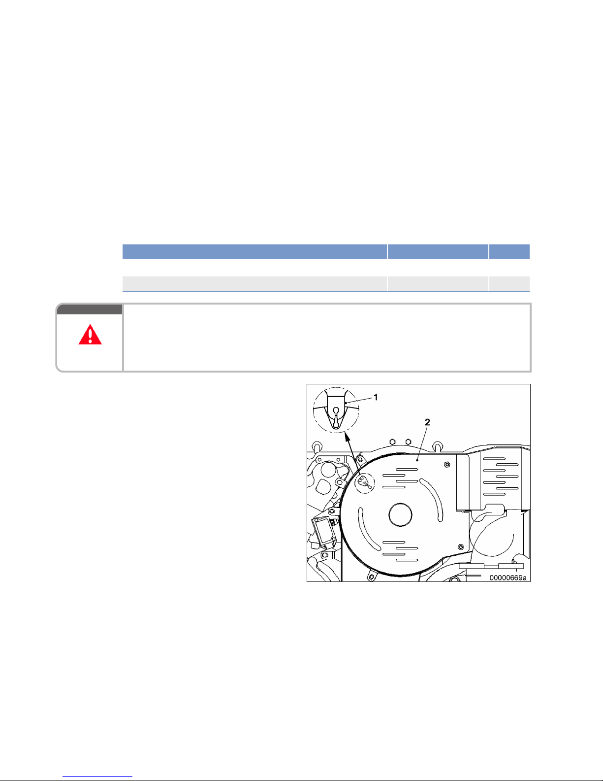
8 Task Description
8.1 Engine
8.1.1 Engine – Barring manually
Preconditions
☑ Engine is stopped and starting disabled.
Special tools, Material, Spare parts
Designation / Use Part No. Qty.
Ratchet
F30006212 1
Socket
F30005655 1
DANGER
Rotating and moving engine parts.
Risk of crushing, danger of parts of the body being caught or pulled in!
• Before barring the engine, make sure that there are no persons in the engine's danger zone.
• After finishing work on the engine, make sure that all safety devices are put back in place and all
tools are removed from the engine.
Barring engine manually
1. Remove cover plate (2).
2. Attach ratchet with socket to barring tool.
3. Rotate crankshaft in engine direction of rotation. No resistance other than compression
resistance may be encountered.
Result: Contact Service, if the resistance exceeds
the normal compression resistance.
4. For barring tool removal follow reverse sequence of working steps.
64 | Task Description | MW15409/04E 2015-08
TIM-ID: 0000002525 - 005
Page 65
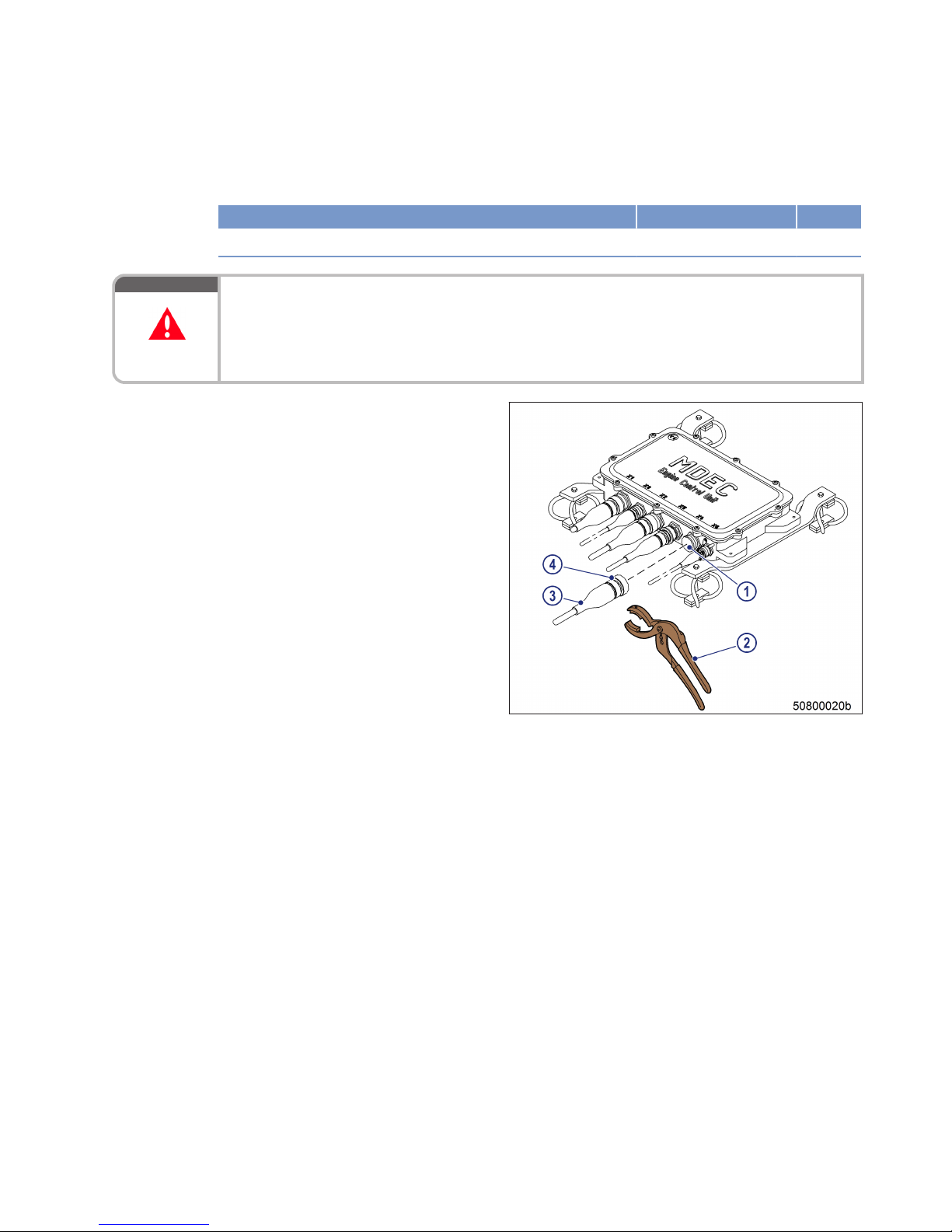
8.1.2 Engine – Barring with starting system
Special tools, Material, Spare parts
Designation / Use Part No. Qty.
Connector pliers
0135315483 1
DANGER
Rotating and moving engine parts.
Risk of crushing, danger of parts of the body being caught or pulled in!
• Before barring the engine, make sure that there are no persons in the engine's danger zone.
• After finishing work on the engine, make sure that all safety devices are put back in place and all
tools are removed from the engine.
Engine – Barring with starting
system
1. Disengage the bayonet coupling (4) of connector X4 with connector pliers (2) and disconnect connector (3) from engine governor.
2. Bar engine in unloaded condition: Press
START button.
3. Let the crankshaft rotate until oil pressure is
indicated.
4. Engine start is automatically interrupted
when specified starting period is expired. If
necessary, re-start the engine after approx.
20 seconds.
5. Fit connector X4, turn bayonet coupling (4) of
connector (3) with connector pliers (2) clockwise until it engages.
MW15409/04E 2015-08 | Task Description | 65
TIM-ID: 0000000950 - 004
Page 66

8.2 Cylinder Liner
8.2.1 Cylinder liner – Endoscopic examination
Preconditions
☑ Engine is stopped and starting disabled
Special tools, Material, Spare parts
Designation / Use Part No. Qty.
Rigid endoscope
Y20097353 1
Preparatory steps
1. Remove cylinder head cover (→ Page 76).
2. Remove injector (→ Page 82).
Positioning crankshaft at BDC
1. Using barring gear, turn crankshaft until crankshaft journal of the cylinder to be inspected has reached BDC.
2. Insert endoscope into cylinder liner through injector seat.
Cylinder liner – Endoscopic examination
Findings Task
• Thin carbon coating around circumference of carbon scraper ring
• Slight localized additive deposits at top edge
• Localized smooth areas at bottom edge
• Carbon deposits around circumference between top piston ring and
bottom edge of carbon scraper ring
• First signs of marks left by top piston ring
• Bright mark around circumference
• Faultless, even honing pattern
• First signs of marks left by lower cooling bores
• Running pattern seems darker
No action required.
• Darker areas of even or varying color intensity
• Beginning and end of the discoloration are not sharply defined and do
not cover the entire stroke area
• Dark areas in the upper section of the cooling bore, remaining circumference cannot be faulted
• Piston rings faultless
Further endoscopic examination required as part of maintenance work.
• On the entire circumference not only bright discoloration (not critical
for operation) clearly visible darker stripes that begin at the top piston
ring
• Heat discoloration in the direction of stroke and honing pattern damage
• Heat discoloration of piston rings
Cylinder liner must be replaced,
contact Service.
1. Compile endoscopy report using the table.
2. Use technical terms for description of the liner surface (→ Page 68).
3. Depending on findings:
• Do not take any action or
• Carry out further endoscopic examination as part of maintenance work or
• Contact Service; cylinder liner must be replaced.
66 | Task Description |
MW15409/04E 2015-08
TIM-ID: 0000000015 - 016
Page 67

Final steps
1. Install injector (→ Page 82).
2. Install cylinder head cover (→ Page 76).
MW15409/04E 2015-08 | Task Description | 67
TIM-ID: 0000000015 - 016
Page 68

8.2.2 Instructions and comments on endoscopic and visual examination of cylinder
liners
Terms used for endoscopic examination
Use the terms listed below to describe the condition of the cylinder-liner surface in the endoscopic examination report.
Findings Explanations/Action
Minor dirt scores Minor dirt scores can occur during the assembly of a new engine (honing products,
particles, broken-off burrs). Removed cylinders clearly show such scoring on the
running surface under endoscope magnification. Cannot be felt with the fingernail.
Findings not critical.
Single scores Clearly visible scores caused by hard particles. They usually start in the TDC area
and cross through the hone pattern in the direction of stroke.
Findings not critical.
Scored area These areas consist of scores of different length and depth next to one another. In
most cases, they are found at the 6-o'clock and 12-o'clock positions (inlet/
exhaust) along the transverse engine axis.
Findings not critical.
Smoothened area Smoothened areas are on the running surface but almost the whole honing pattern
is still visible. Smoothened areas appear brighter and more brilliant than the surrounding running surface.
Findings not critical.
Bright area Bright areas are on the running surface and show local removal of the honing pat-
tern. Grooves from honing process are not visible any more.
Discoloration This is caused by oxidation (surface discoloration through oil or fuel) and tempera-
ture differences around the liner. It appears rather darker within the honed structure in contrast to the bright metallic running surface. The honing pattern is undisturbed. Discolorations extend in stroke direction and may be interrupted.
Findings not critical.
Corrosion fields /
spots
Corrosion fields / spots result from water (condensed water) with the valves in the
overlap (open) position. They are clearly visible due to the dark color of the honing
groove bottom.
This corrosion is not critical unless there is corrosion pitting.
Black lines Black lines are a step towards heat discoloration. They are visible as a clear discol-
oration from TDC to BDC in the running surface and the start of localized damage
to the honing pattern.
Cylinder liners with a large number of black lines around the running surface have
limited service life and should be replaced.
Burn mark This is caused by a malfunction in the liner / ring tribosystem. Usually they run
over the whole ring-travel area (TDC/BDC), starting at the first TDC-ring and becoming more visible from the second TDC-ring 2 onwards and less pronounced
from TDC-ring 1. The honing pattern is usually no longer visible and displays a
clearly defined (straight) edge to the undisturbed surface. The damaged surface is
usually discolored. The circumferential length varies.
Liners with burn marks, or heat discoloration, starting in TDC-ring 1 have to be replaced.
Seizure marks, scuffing
Irregular circumference lengths and depths. Can be caused either by the piston
skirt or the piston crown. Material deposits on the liner (smear), heavy discoloration. Severe, visible scoring.
Replace liner.
68 | Task Description | MW15409/04E 2015-08
TIM-ID: 0000000014 - 015
Page 69

Evaluation of findings and further measures
The findings in the start phase of oxidation discoloration and heat discoloration are similar. A thorough investigation and compliance with the above evaluation criteria allow an unambiguous evaluation. To avoid unnecessary disassembly work, it is recommended that another inspection be carried out after further operation of
the engine.
MW15409/04E 2015-08 | Task Description | 69
TIM-ID: 0000000014 - 015
Page 70
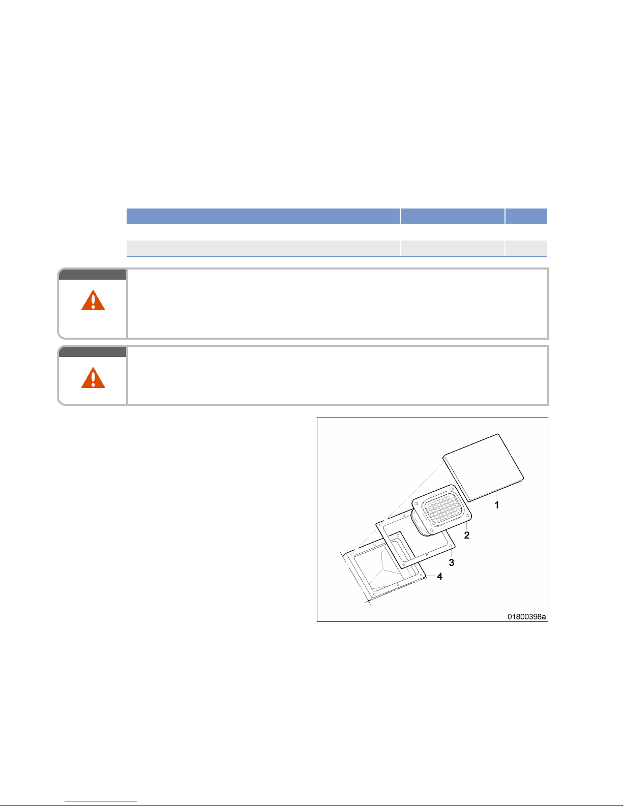
8.3 Crankcase Breather
8.3.1 Crankcase breather – Cleaning oil pre-separator element
Preconditions
☑ Engine is stopped and starting disabled.
Special tools, Material, Spare parts
Designation / Use Part No. Qty.
Fuel
Gasket
(→ Spare Parts Catalog)
WARNING
Fuels are combustible and explosive.
Risk of fire and explosion!
• Avoid open flames, electrical sparks and ignition sources.
• Do not smoke.
• Wear protective clothing, protective gloves, and safety glasses / facial protection.
WARNING
Compressed air gun ejects a jet of pressurized air.
Risk of injury to eyes and damage to hearing, risk of rupturing internal organs!
• Never direct air jet at people.
• Always wear safety goggles/face mask and ear defenders.
Crankcase breather – Cleaning
oil pre-separator element
1. Remove cover (1) from housing (4).
2. Remove oil separator (2) and gasket (3).
3. Clean oil separator (2) in fuel and blow dry
with compressed air.
4. Moisten oil separator (2) with engine oil.
5. Place oil separator (2) with new gasket (3)
onto housing (4) and install cover (1).
6. Clean other oil pre-separator element in the
same way.
70 | Task Description | MW15409/04E 2015-08
TIM-ID: 0000003470 - 008
Page 71
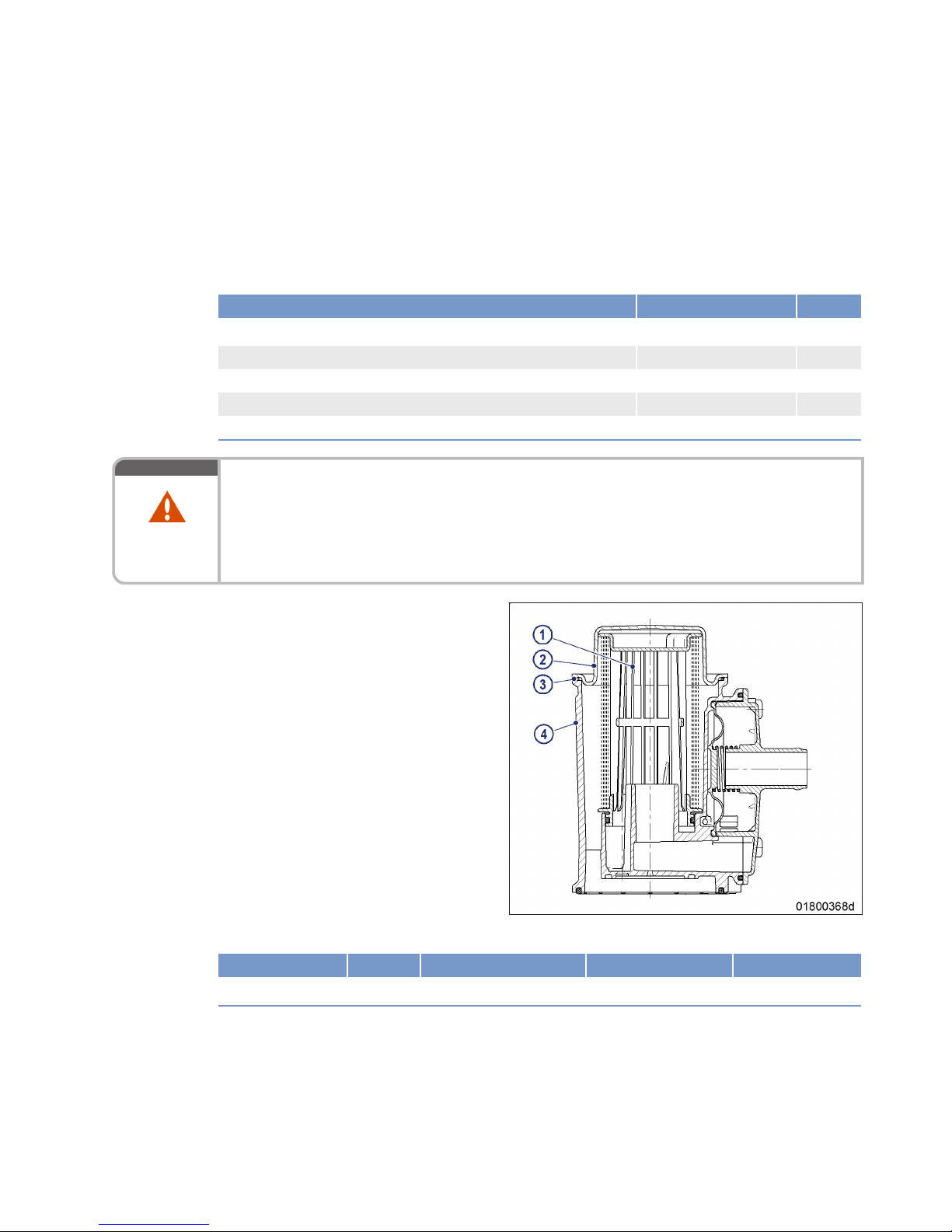
8.3.2 Crankcase breather – Oil separator replacement, diaphragm check and
replacement
Preconditions
☑ Engine is stopped and starting disabled.
Special tools, Material, Spare parts
Designation / Use Part No. Qty.
Torque wrench, 6–50 Nm
F30027336 1
Ratchet adapter
F30027340 1
Filter element
(→ Spare Parts Catalog)
Diaphragm
(→ Spare Parts Catalog)
O-ring
(→ Spare Parts Catalog)
WARNING
Hot oil.
Oil can contain combustion residues which are harmful to health.
Risk of injury and poisoning!
• Wear protective clothing, gloves, and goggles / safety mask.
• Avoid contact with skin.
• Do not inhale oil vapor.
Replacing filter element of oil
separator
1. Remove cover (2) with O-ring (3).
2. Remove filter element (1) from housing (4).
3. Insert new filter element into housing (4) ensuring correct installation position, and fit
cover (2) with new O-ring.
4. Use torque wrench to tighten screws on cover (2) to specified tightening torque.
Name Size Type Lubricant Value/Standard
Screw Tightening torque 6 Nm +2 Nm
5. Replace filter elements of further oil separators in the same way.
MW15409/04E 2015-08
| Task Description | 71
TIM-ID: 0000003491 - 005
Page 72
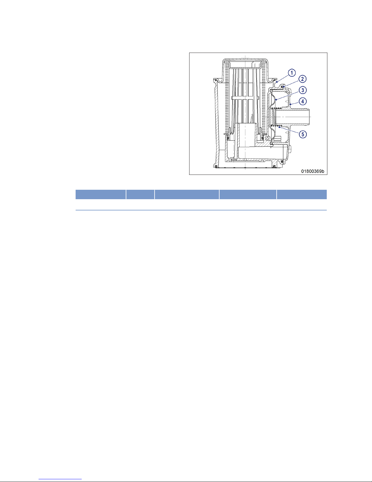
Checking diaphragm
1. Remove cover (4).
2. Remove spring (5), seal (2) and diaphragm (3).
3. Check diaphragm (3) for damage, fit new diaphragm if used one is damaged.
4. Install diaphragm (3) on housing (1).
5. Install new seal (2) and spring (5) together
with cover (4).
6. Use torque wrench to tighten the screws of cover (4) to the specified torque.
Name Size Type Lubricant Value/Standard
Screw Tightening torque 6 Nm +2 Nm
7. Check diaphragms in further oil separators in the same way.
72 | Task Description | MW15409/04E 2015-08
TIM-ID: 0000003491 - 005
Page 73
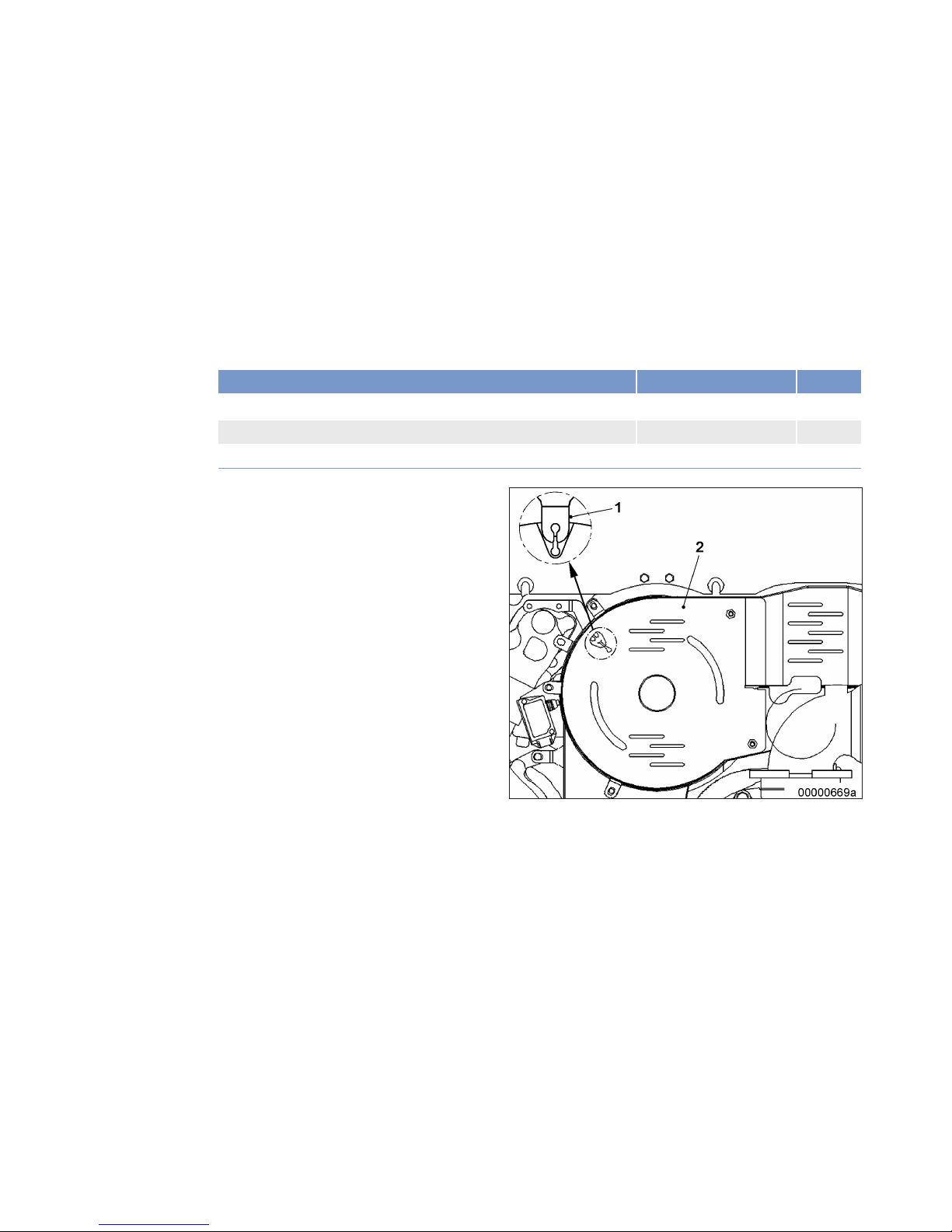
8.4 Valve Drive
8.4.1 Valve clearance – Check and adjustment
Preconditions
☑ Engine is stopped and starting disabled.
☑ Engine coolant temperature is max. 40 °C.
☑ Valves are closed.
Special tools, Material, Spare parts
Designation / Use Part No. Qty.
Torque wrench, 20–100 Nm
F30026582 1
Box wrench bit, 17 mm
F30030450 1
Feeler gauge
Y4342013 1
Preparatory steps
1. Remove cover plate (2).
2. Remove cylinder head cover (→ Page 76).
3. Bar engine manually in engine direction of rotation until the markings (1) are aligned.
MW15409/04E 2015-08 | Task Description | 73
TIM-ID: 0000004360 - 006
Page 74
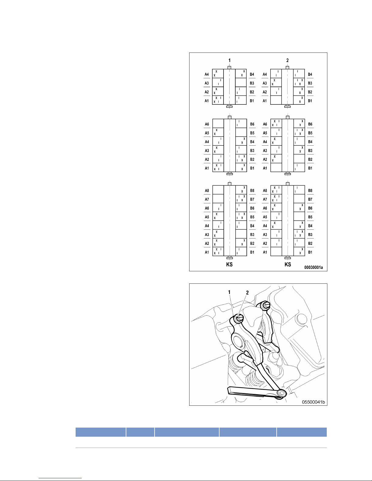
Checking valve clearance at two
crankshaft positions
1. Check TDC position of piston in cylinder A1:
• If the rocker arms are not under load on
cylinder A1, the piston is in firing TDC.
• If the rocker arms are under load on cylinder A1, the piston is in overlap TDC.
2. Check valve clearance with the engine cold:
• Inlet = 0.4 mm;
• Exhaust = 0.6 mm;.
3. Check all valve clearances in two crankshaft
positions (firing TDC and overlap TDC of cylinder A1) as per diagram:
1 Cylinder A1 is in firing TDC
2 Cylinder A1 is in overlap TDC
I Inlet valve
X Exhaust valve
4. Use feeler gauge to determine the distance
between valve bridge and rocker arm.
5. If the deviation from the set value exceeds
0.1 mm, adjust valve clearance.
Adjusting valve clearance
1. Loosen locknut (1) and unscrew adjusting
screw (2) slightly.
2. Insert feeler gauge between valve bridge and
rocker arm.
3. Readjust adjusting screw (2) so that the feeler gauge just passes through the gap.
4. Tighten locknut (1) applying the specified tightening torque, holding adjusting screw (2) firmly with screwdriver.
Name Size Type Lubricant Value/Standard
Locknut M12x1 Tightening torque 50 Nm
74 | Task Description | MW15409/04E 2015-08
TIM-ID: 0000004360 - 006
Page 75

5. Insert feeler gauge between valve bridge and rocker arm to verify that the gauge just passes through the
gap.
Result: If not, adjust valve clearance.
Final steps
1. Remove barring device.
2. For installation of removed parts, follow reverse sequence of working steps.
MW15409/04E 2015-08 | Task Description | 75
TIM-ID: 0000004360 - 006
Page 76
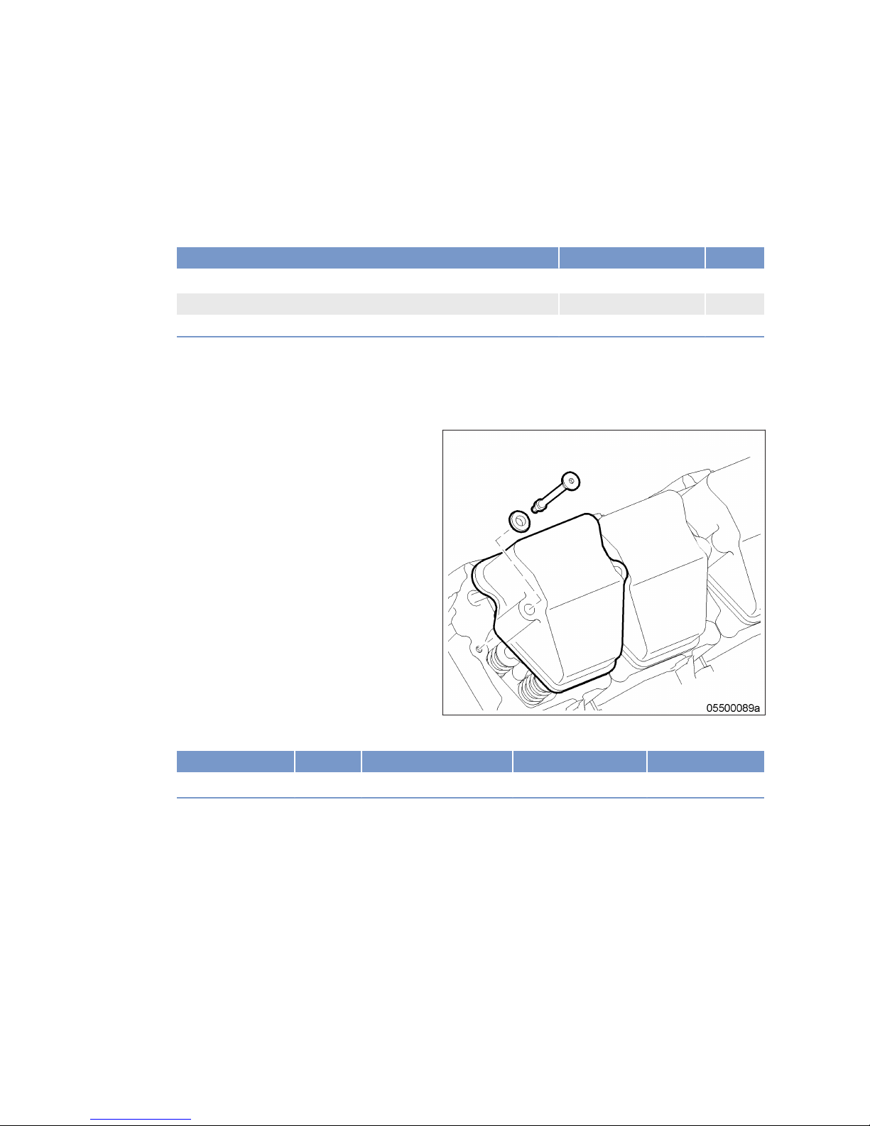
8.4.2 Cylinder head cover – Removal and installation
Preconditions
☑ Engine is stopped and starting disabled.
Special tools, Material, Spare parts
Designation / Use Part No. Qty.
Torque wrench, 6–50 Nm
F30027336 1
Ratchet adapter
F30027340 1
Gasket
(→ Spare Parts Catalog)
Preparatory steps
1. Remove air filter (→ Page 110).
2. Remove mounting bracket with control valves for exhaust turbocharger and air flap switching.
Removing and installing cylinder head cover
1. Remove screws.
2. Remove cylinder head cover with gasket from
cylinder head.
3. Clean installation surface.
4. Check condition of profile gasket in cylinder
head cover.
5. Replace damaged gaskets.
6. Place cylinder head covers onto crankcase and tighten screws to specified tightening torque.
Name Size Type Lubricant Value/Standard
Screw Tightening torque 20 Nm
Final steps
1. Install mounting bracket with control valves for exhaust turbocharger and air flap switching.
2. Install air filter (→ Page 110).
76 | Task Description |
MW15409/04E 2015-08
TIM-ID: 0000004466 - 005
Page 77

8.5 Injection Pump / HP Pump
8.5.1 Injection pump – Replacement
Special tools, Material, Spare parts
Designation / Use Part No. Qty.
Injection pump
(→ Spare Parts Catalog)
Injection pump – Replacement
u Remove injection pump and install new one (→ Page 78).
MW15409/04E 2015-08 | Task Description | 77
TIM-ID: 0000000020 - 004
Page 78
8.5.2 Injection pump – Removal and installation
Preconditions
☑ Engine is stopped and starting disabled.
Special tools, Material, Spare parts
Designation / Use Part No. Qty.
Torque wrench, 20-100 Nm
F30026582 1
Ratchet adapter
F30027340 1
Box wrench
F30038493 1
Spider patch spanner
F30027424 1
Spider patch spanner
F30027425 1
Torque wrench, 0.5-5 Nm
0015384230 1
Assembly compound (Kluthe Hakuform 30-15)
X00067260
Sealing ring
(→ Spare Parts Catalog)
Sealing ring
(→ Spare Parts Catalog)
DANGER
Rotating and moving engine parts.
Risk of crushing, danger of parts of the body being caught or pulled in!
• Before cranking the engine with starter system, make sure that there are no persons in the engine's
danger zone.
WARNING
Fuels are combustible and explosive.
Risk of fire and explosion!
• Avoid open flames, electrical sparks and ignition sources.
• Do not smoke.
• Wear protective clothing, protective gloves, and safety glasses / facial protection.
Preparatory steps
1. Close fuel supply line upstream of fuel filter.
2. Remove engine control system (→ Page 149).
3. Drain fuel (→ Page 87).
4. Remove charge-air pipes and all seals.
78 | Task Description | MW15409/04E 2015-08
TIM-ID: 0000004579 - 008
Page 79
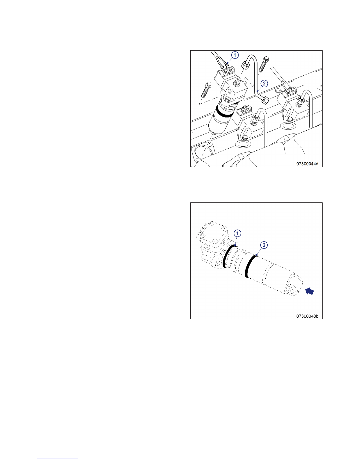
Removing injection pump
1. Mark installation position of injection pump.
2. Disconnect cabling (1) from injection pump.
3. Remove fuel line (2).
4. Unscrew securing screws of injection pump
by approx. 6 mm.
Result: The preloaded compression spring presses
the injection pump out of the crankcase; If
not:
• Turn crankshaft with barring tool
(→ Page 64).
The pump cam on the camshaft presses
the injection pump out of the crankcase; if
not:
• Carefully press out injection pump at the
recess in the injection pump head.
5. Remove injection pump securing screws.
6. Remove injection pump.
7. Remove sealing rings from injection pump.
8. After removal, seal all openings with suitable
covers.
Installing injection pump
1. Remove all blanking plugs and covers.
2. Clean mating face of injection pump and roller.
Note: Sealing ring (1) Ø47 mm
3. Coat sealing ring (1) with assembly compound and fit onto injection pump.
Note: Sealing ring (2) Ø45 mm
4. Coat sealing ring (2) with assembly compound and fit onto injection pump.
5. Coat roller (arrowed) with engine oil.
6. Clean sealing face and fuel bores in crankcase.
7. Use barring tool (→ Page 64) to position the
pump cams on the camshaft at base circle.
MW15409/04E 2015-08 | Task Description | 79
TIM-ID: 0000004579 - 008
Page 80
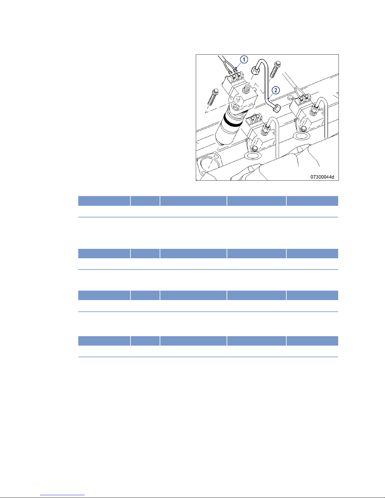
8. Install injection pump, observing marked installation position.
9. Install securing screws of injection pump and tighten to specified torque using a torque wrench.
Name Size Type Lubricant Value/Standard
Securing screw Tightening torque 60 Nm + 12 Nm
10. Install fuel line (2).
11. Tighten union nut on injection pump to specified torque using a torque wrench.
• Maximum permissible tightening torque: 35 Nm
Name Size Type Lubricant Value/Standard
Union nut Tightening torque 20 Nm + 5 Nm
12. Tighten union nut on pressure pipe neck to specified torque using a torque wrench.
• Maximum permissible tightening torque: 35 Nm
Name Size Type Lubricant Value/Standard
Union nut Tightening torque 20 Nm + 5 Nm
13. Install injection pump cabling (1).
14. Tighten screws to specified torque using a torque wrench.
Name Size Type Lubricant Value/Standard
Screw Tightening torque 1.0 Nm ± 0.2 Nm
Final steps
1. Remove engine barring tool (→ Page 64).
2. Clean mating faces on cylinder head and charge-air manifold.
3. Check gaskets for damage and replace them, if required.
4. Coat gaskets with assembly compound and place onto cylinder head.
5. Install charge-air pipes.
6. Install engine control system (→ Page 149).
7. Open fuel supply line upstream of fuel filter.
8. Vent fuel system (→ Page 88).
80 | Task Description |
MW15409/04E 2015-08
TIM-ID: 0000004579 - 008
Page 81

8.6 Injection Valve / Injector
8.6.1 Injector – Replacement
Special tools, Material, Spare parts
Designation / Use Part No. Qty.
Injector
(→ Spare Parts Catalog)
Replacing injector
u Remove injector and install new injector (→ Page 82).
MW15409/04E 2015-08 | Task Description | 81
TIM-ID: 0000000022 - 016
Page 82
8.6.2 Injector – Removal and installation
Preconditions
☑ Engine is stopped and starting disabled.
Special tools, Material, Spare parts
Designation / Use Part No. Qty.
Puller
3555890163/00 1
Fuel suction device
F30378207 1
Torque wrench, 20-100 Nm
F30026582 1
Ratchet adapter
F30027340 1
Open-end wrench bit
F30025897 1
Spider patch spanner
F30027425 1
Spider patch spanner
F30027424 1
Double-head box wrench
F30011450 1
Ratchet adapter
F30027340 1
Assembly compound (Kluthe Hakuform 30-15)
X00067260 1
Sealing ring
(→ Spare Parts Catalog)
Sealing ring
(→ Spare Parts Catalog)
WARNING
Fuels are combustible and explosive.
Risk of fire and explosion!
• Avoid open flames, electrical sparks and ignition sources.
• Do not smoke.
• Wear protective clothing, protective gloves, and safety glasses / facial protection.
WARNING
Compressed air gun ejects a jet of pressurized air.
Risk of injury to eyes and damage to hearing, risk of rupturing internal organs!
• Never direct air jet at people.
• Always wear safety goggles/face mask and ear defenders.
Preparatory steps
1. Remove cylinder head cover (→ Page 76).
2. Drain fuel (→ Page 87).
82 | Task Description | MW15409/04E 2015-08
TIM-ID: 0000004646 - 008
Page 83
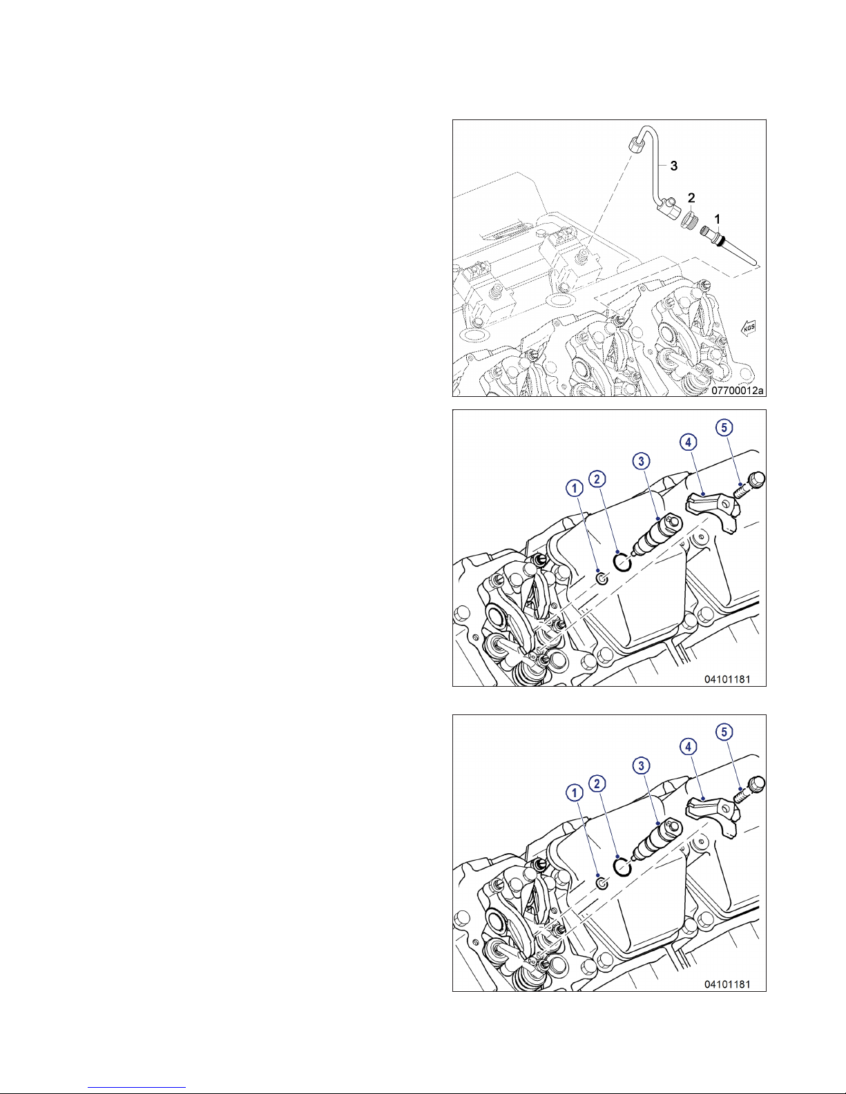
Removing injector
1. Remove leak-off-fuel lines.
2. Remove fuel line (3).
3. Remove thrust screw (2).
4. Pull off pressure pipe neck (1).
5. Extract fuel from the exposed bores using the
suction device.
6. Remove screw (5).
7. Remove clamp (4).
8. Screw puller into injector.
9. Remove injector with puller.
10. Remove injector sealing ring (1) using a selfmade hook.
11. After removal, seal all openings with suitable
covers.
Installing injector
1. Remove all covers before installation.
2. Clean sealing surface on cylinder head and
protective sleeve.
3. Coat sealing ring (1) with assembly compound and fit onto injector.
4. Coat sealing ring (2) with assembly compound and fit onto injector.
5. Press injector (3) into cylinder head by hand.
Result: • The pin is at 11-o'clock position to the
transversal axis of the engine.
• Pin is in recess of clamp (4).
6. Install clamp (4) with screw (5), positioning it
correctly.
Result: • Pin on injector is in the recess in the
clamp.
• Forked clamp end is engaged in the cover
recess.
7. Tighten screw (5) of the clamp by hand.
Result: Injector can still be turned.
MW15409/04E 2015-08 | Task Description | 83
TIM-ID: 0000004646 - 008
Page 84
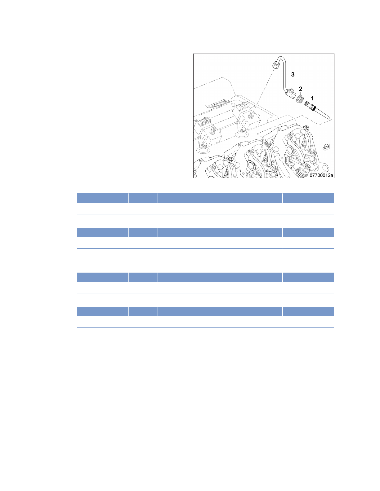
8. Blow out fuel line (3) and pressure pipe
neck (1) with compressed air.
9. Coat sealing ring with assembly compound
and fit onto pressure pipe neck (1).
10. Coat sealing cone of pressure pipe neck with
engine oil.
11. Insert pressure pipe neck into cylinder head
until it is in contact with the sealing ring.
12. Fully press in pressure pipe neck (1) by hand.
13. Tighten thrust screw (2) to specified torque using a torque wrench.
Name Size Type Lubricant Value/Standard
Thrust screw Tightening torque 40 Nm ±5 Nm
14. Tighten screw for clamp at injector to specified torque using a torque wrench.
Name Size Type Lubricant Value/Standard
Screw Tightening torque 50 Nm
15. Install fuel line (3).
16. Tighten union nut on injection pump to specified torque using a torque wrench.
Name Size Type Lubricant Value/Standard
Union nut Tightening torque 20 Nm +5 Nm
17. Tighten union nut on pressure pipe neck to specified torque using a torque wrench.
Name Size Type Lubricant Value/Standard
Union nut Tightening torque 20 Nm +5 Nm
18. Install leak-off-fuel lines.
Final steps
1. Install cylinder head cover (→ Page 76).
2. Vent fuel system (→ Page 88).
84 | Task Description |
MW15409/04E 2015-08
TIM-ID: 0000004646 - 008
Page 85
8.7 Fuel System
8.7.1 HP fuel line – Pressure pipe neck replacement
Preconditions
☑ Engine is stopped and starting disabled.
Special tools, Material, Spare parts
Designation / Use Part No. Qty.
Torque wrench, 20-100 Nm
F30026582 1
Open-end wrench bit
F30025897 1
Spider patch spanner
F30027425 1
Spider patch spanner
F30027424 1
Double-head box wrench
F30011450 1
Ratchet adapter
F30027340 1
Assembly compound (Kluthe Hakuform 30-15)
X00067260
Engine oil
Pressure pipe neck
(→ Spare Parts Catalog)
WARNING
Fuels are combustible and explosive.
Risk of fire and explosion!
• Avoid open flames, electrical sparks and ignition sources.
• Do not smoke.
• Wear protective clothing, protective gloves, and safety glasses / facial protection.
WARNING
Compressed air gun ejects a jet of pressurized air.
Risk of injury to eyes and damage to hearing, risk of rupturing internal organs!
• Never direct air jet at people.
• Always wear safety goggles/face mask and ear defenders.
Preparatory steps
1. Remove cylinder head cover (→ Page 76).
2. Drain fuel (→ Page 87).
MW15409/04E 2015-08 | Task Description | 85
TIM-ID: 0000004678 - 007
Page 86
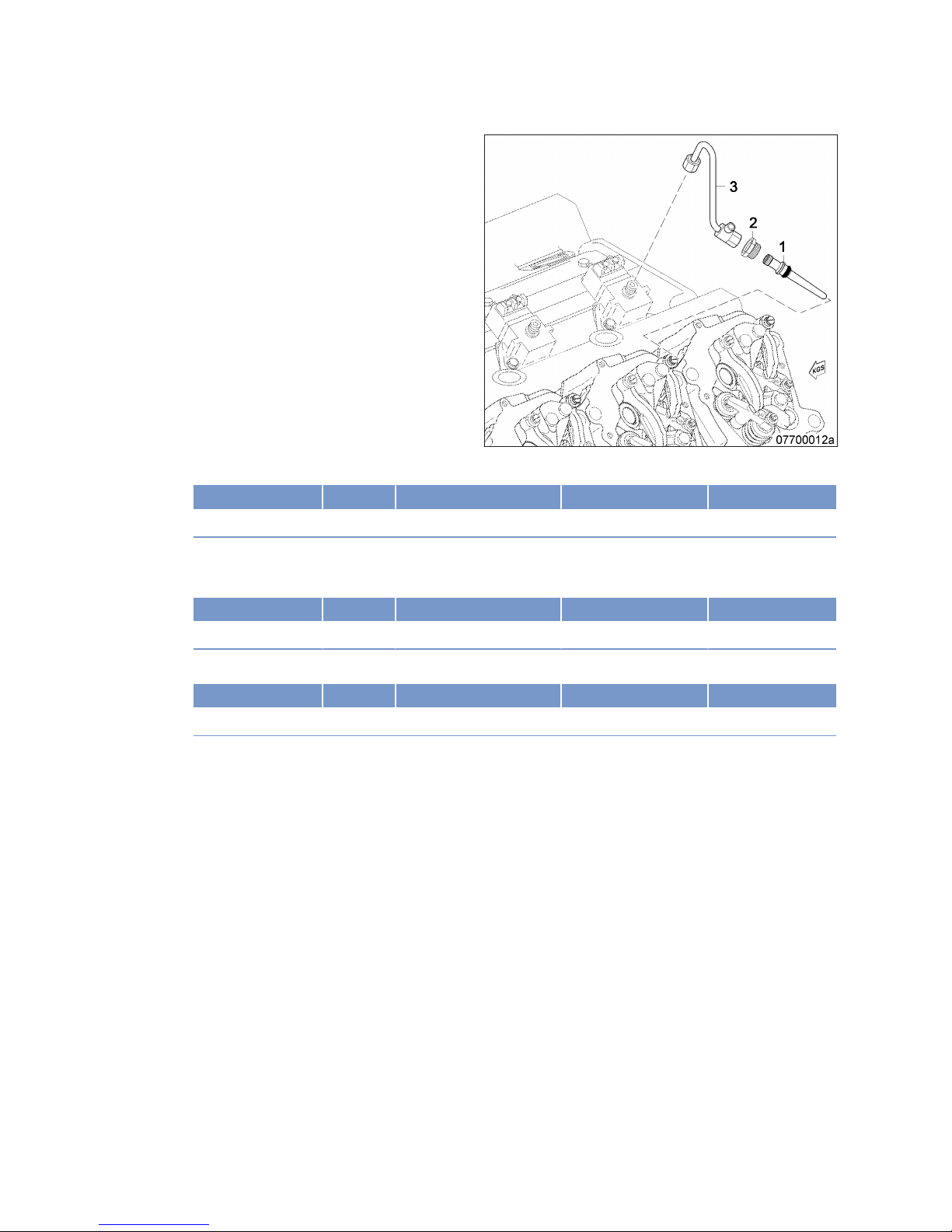
Replacing pressure pipe neck
1. Remove fuel line (3).
2. Remove thrust screw (2).
3. Pull off pressure pipe neck (1).
4. Coat sealing ring with assembly compound
and fit on new pressure pipe neck (1).
5. Blow out fuel line (3) with compressed air.
6. Coat sealing cone of pressure pipe neck with
engine oil.
7. Insert pressure pipe neck into cylinder head
until it is in contact with the sealing ring.
8. Fully press in pressure pipe neck (1) by hand.
9. Tighten thrust screw (2) to specified torque using a torque wrench.
Name Size Type Lubricant Value/Standard
Thrust screw Tightening torque 40 Nm ± 5 Nm
10. Install fuel line (3).
11. Tighten union nut on injection pump to specified torque using a torque wrench.
Name Size Type Lubricant Value/Standard
Union nut Tightening torque 20 Nm + 5 Nm
12. Tighten union nut on pressure pipe neck to specified torque using a torque wrench.
Name Size Type Lubricant Value/Standard
Union nut Tightening torque 20 Nm + 5 Nm
Final steps
1. Install cylinder head cover (→ Page 76).
2. Vent fuel system (→ Page 88).
86 | Task Description | MW15409/04E 2015-08
TIM-ID: 0000004678 - 007
Page 87
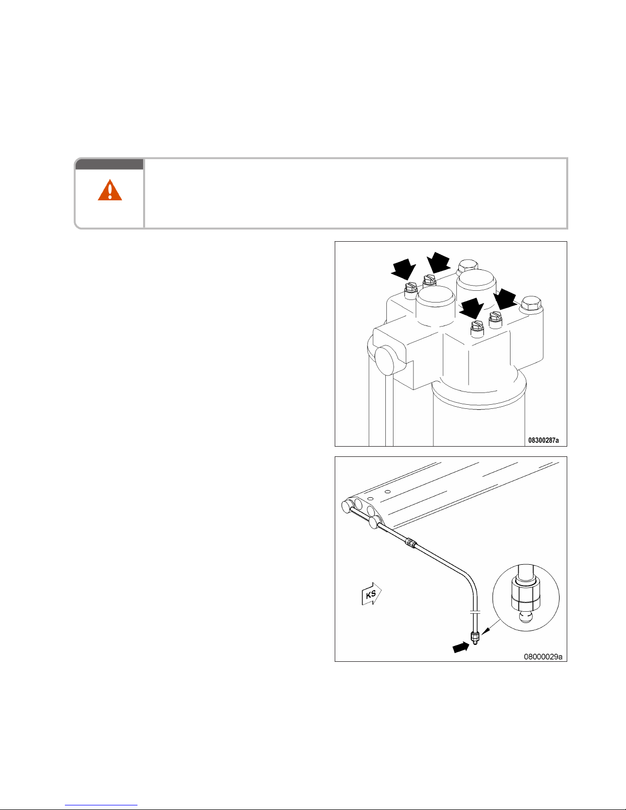
8.7.2 Fuel – Draining
Preconditions
☑ Engine is stopped and starting disabled.
WARNING
Fuels are combustible and explosive.
Risk of fire and explosion!
• Avoid open flames, electrical sparks and ignition sources.
• Do not smoke.
• Wear protective clothing, protective gloves, and safety glasses / facial protection.
Draining fuel
1. Release threaded vent plugs on filter head.
2. Open nipple on fuel line and drain fuel into
appropriate container.
3. When fuel stops emerging from system, close
nipple on fuel line.
4. Close threaded vent plugs on filter head.
MW15409/04E 2015-08 | Task Description | 87
TIM-ID: 0000004703 - 004
Page 88
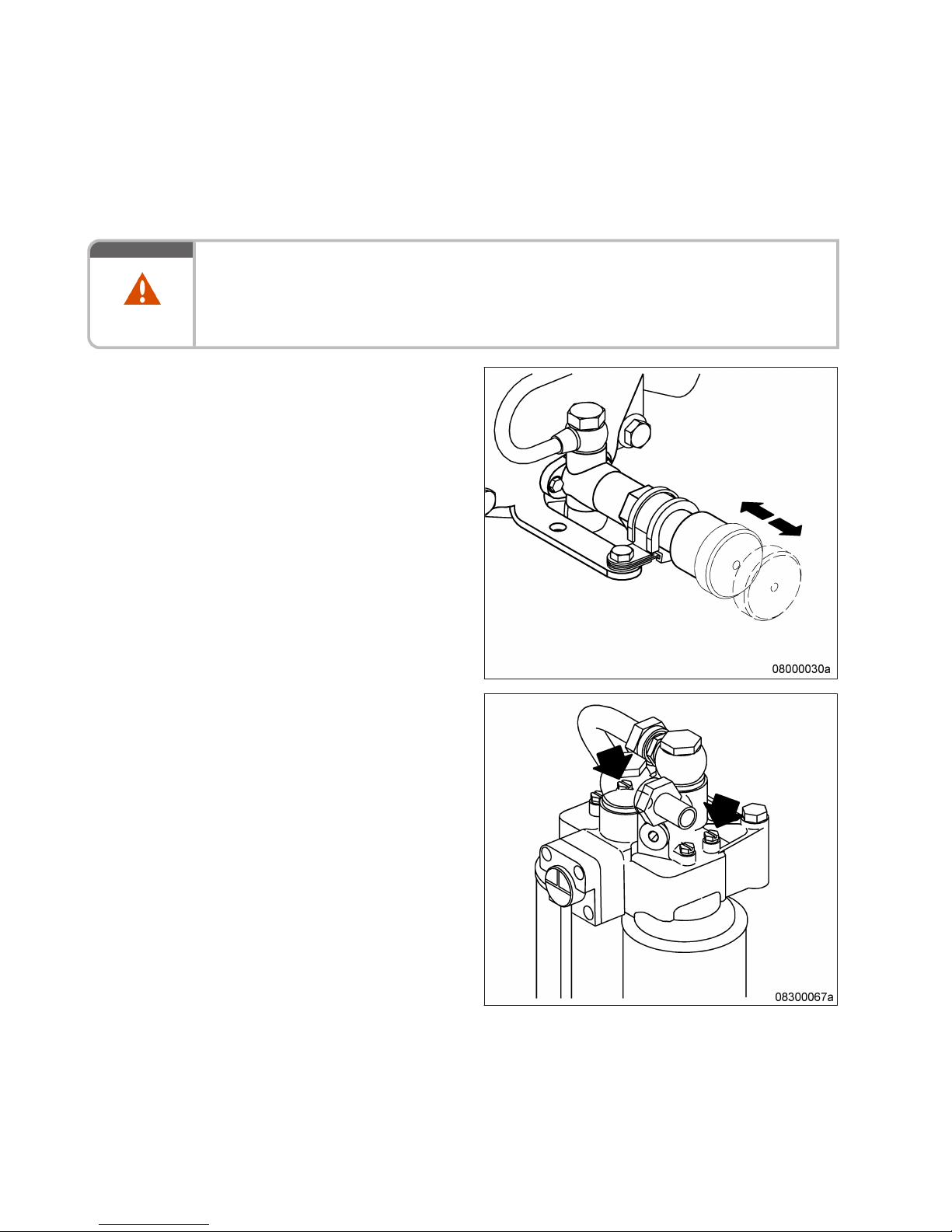
8.7.3 Fuel system – Venting
Preconditions
☑ Engine is stopped and starting disabled.
WARNING
Fuels are combustible and explosive.
Risk of fire and explosion!
• Avoid open flames, electrical sparks and ignition sources.
• Do not smoke.
• Wear protective clothing, protective gloves, and safety glasses / facial protection.
Venting fuel system
1. Unlock fuel priming pump, unscrew handle.
2. Open threaded vent plugs on filter head.
3. Operate the pump with the handle until bubble-free fuel emerges at the threaded vent
plugs.
4. Close threaded vent plugs on filter head.
88 | Task Description | MW15409/04E 2015-08
TIM-ID: 0000004712 - 003
Page 89
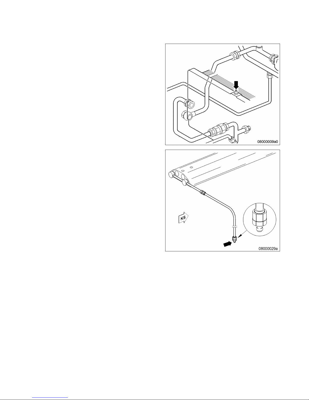
5. Open nipple at fuel heat exchanger.
6. Operate the pump with the handle until bubble-free fuel emerges at the nipple.
7. Close nipple at fuel heat exchanger.
8. Open nipple at fuel line.
9. Operate the pump with the handle until bubble-free fuel emerges at the nipple.
10. Close nipple on fuel line.
11. Lock fuel priming pump, screw in handle.
MW15409/04E 2015-08 | Task Description | 89
TIM-ID: 0000004712 - 003
Page 90
8.8 Fuel Filter
8.8.1 Fuel filter – Replacement
Preconditions
☑ Engine is stopped and starting disabled.
Special tools, Material, Spare parts
Designation / Use Part No. Qty.
Filter wrench
F30379104 1
Fuel
Easy-change filter
(→ Spare Parts Catalog)
Synthetic ring
(→ Spare Parts Catalog)
DANGER
Rotating and moving engine parts.
Risk of crushing, danger of parts of the body being caught or pulled in!
• Only run the engine at low power. Keep away from the engine's danger zone.
WARNING
Fuels are combustible and explosive.
Risk of fire and explosion!
• Avoid open flames, electrical sparks and ignition sources.
• Do not smoke.
• Wear protective clothing, protective gloves, and safety glasses / facial protection.
WARNING
High level of engine noise when the engine is running.
Risk of damage to hearing!
• Wear ear protectors.
NOTICE
Damage to component!
Severe material damage!
• For filter replacement with the engine running, operate the engine at low engine load.
• The filter which is to be replaced must be cut out for a brief period only.
90 | Task Description | MW15409/04E 2015-08
TIM-ID: 0000004911 - 008
Page 91
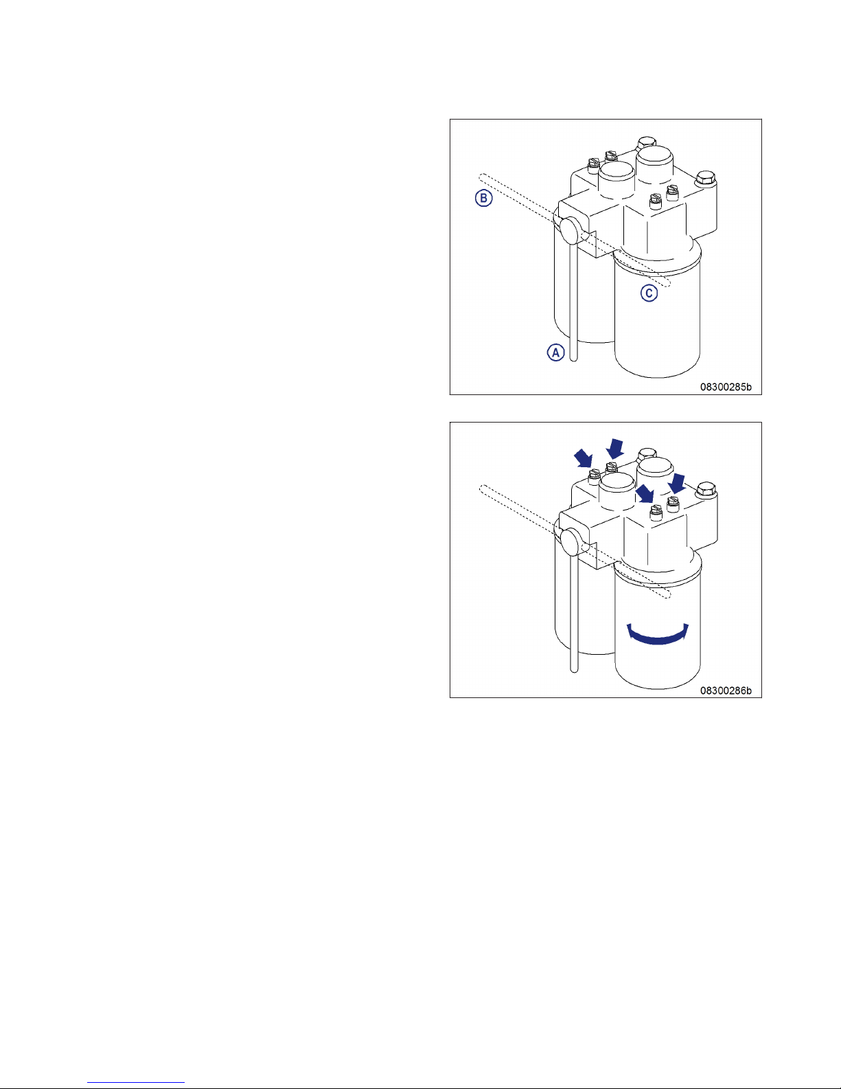
Easy-change fuel filter replacement with the engine stopped
1. Cut out the filter to be replaced.
A Both filters cut in (operating position)
B Left filter cut out
C Right filter cut out
2. Unscrew switched off easy-change filter with
oil filter wrench.
3. Clean sealing surface on filter head.
4. Check seal on new easy-change filter and
moisten with fuel.
5. Fit SOLAS shield (→ Page 21).
6. Install and tighten easy-change filter by hand.
7. Set three-way cock to operating position
(both filters cut in).
8. Replace further fuel filters in the same way.
9. Vent fuel system (→ Page 88).
Easy-change fuel filter replacement with the engine running
1. Cut out the filter to be replaced.
2. Open the threaded vent plugs at the filter
head of the cut-out filter and make sure that
the fuel filter is not pressurized.
3. Close threaded vent plugs.
4. Unscrew switched off easy-change filter with
oil filter wrench.
5. Clean sealing surface on filter head.
6. Check seal on new easy-change filter and
moisten with fuel.
7. Fit SOLAS shield (→ Page 21).
8. Install and tighten easy-change filter by hand.
9. Set three-way cock to operating position
(both filters cut in).
10. Replace further fuel filters in the same way.
MW15409/04E 2015-08 | Task Description | 91
TIM-ID: 0000004911 - 008
Page 92
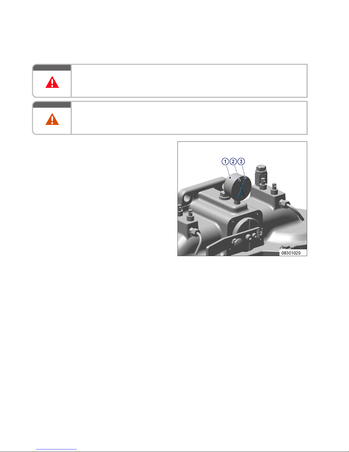
8.8.2 Fuel prefilter – Differential pressure check and adjustment of gauge
DANGER
Rotating and moving engine parts.
Risk of crushing, danger of parts of the body being caught or pulled in!
• Only run the engine at low power. Keep away from the engine's danger zone.
WARNING
High level of engine noise when the engine is running.
Risk of damage to hearing!
• Wear ear protectors.
Setting adjustable pointer of differential pressure gauge
1. After installation of a new filter element, align
adjustable pointer (2) with pressure-indicating pointer (3) of pressure gauge (1).
2. Verify that differential pressure is within the
limit.
Fuel prefilter – checking differential pressure
1. With the engine running at full load or rated power, read off pressure at gauge (1).
2. If differential pressure as indicated between position of adjustable pointer (2) and pressure-indicating pointer (3) of pressure gauge is ≥ 0.3 bar, flush filter element of the cut-in filter (→ Page 95).
92 | Task Description | MW15409/04E 2015-08
TIM-ID: 0000045555 - 001
Page 93
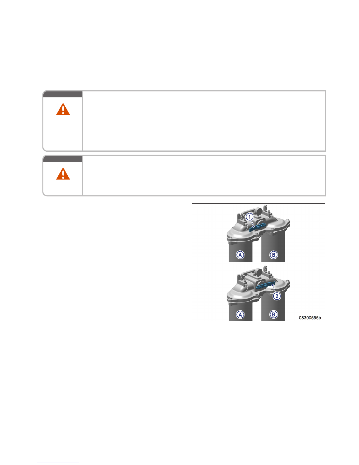
8.8.3 Fuel prefilter – Draining
Preconditions
☑ Engine is stopped and starting disabled.
WARNING
Liquid or gaseous media, e.g. fuel, are poisonous.
Escaping vapors of highly volatile media, e.g. fuel or ether.
Risk of fatal injury through swallowing; risk of poisoning through inhalation; irritation to eyes
and skin!
• Seek medical attention immediately; do not induce vomiting.
• Do not inhale vapors or mist.
• Wear protective clothing, protective gloves, and safety glasses.
• If contact is made with skin, wash off with water and soap.
WARNING
Fuels are combustible and explosive.
Risk of fire and explosion!
• Avoid open flames, electrical sparks and ignition sources.
• Do not smoke.
• Wear protective clothing, protective gloves, and safety glasses / facial protection.
Draining fuel prefilter
1. Switch off filter which is to be drained (A or
B):
1 Filter A cut out
2 Filter B cut out
MW15409/04E 2015-08 | Task Description | 93
TIM-ID: 0000045553 - 004
Page 94
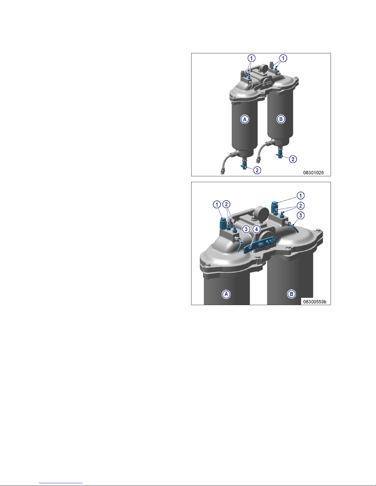
2. Open threaded vent plug (1) of the filter to be
drained.
3. Open drain valve (2).
4. Drain water and contaminants from the filter
until pure fuel emerges.
5. Close drain valve (2).
6. Connect filling pump to filling connection (1)
on the intake side of the filter.
7. Open vent valve (2) and fill with fuel until fuel
emerges from the vent pipe (3).
8. Close vent valve (2).
9. Open rotary slide valve (4) a little (by approx.
30°) and open vent valve(s) (2), until fuel
emerges from the vent pipe (3).
10. Close vent valve(s) (2).
11. Turn rotary slide valve (4) back to locked position.
94 | Task Description | MW15409/04E 2015-08
TIM-ID: 0000045553 - 004
Page 95
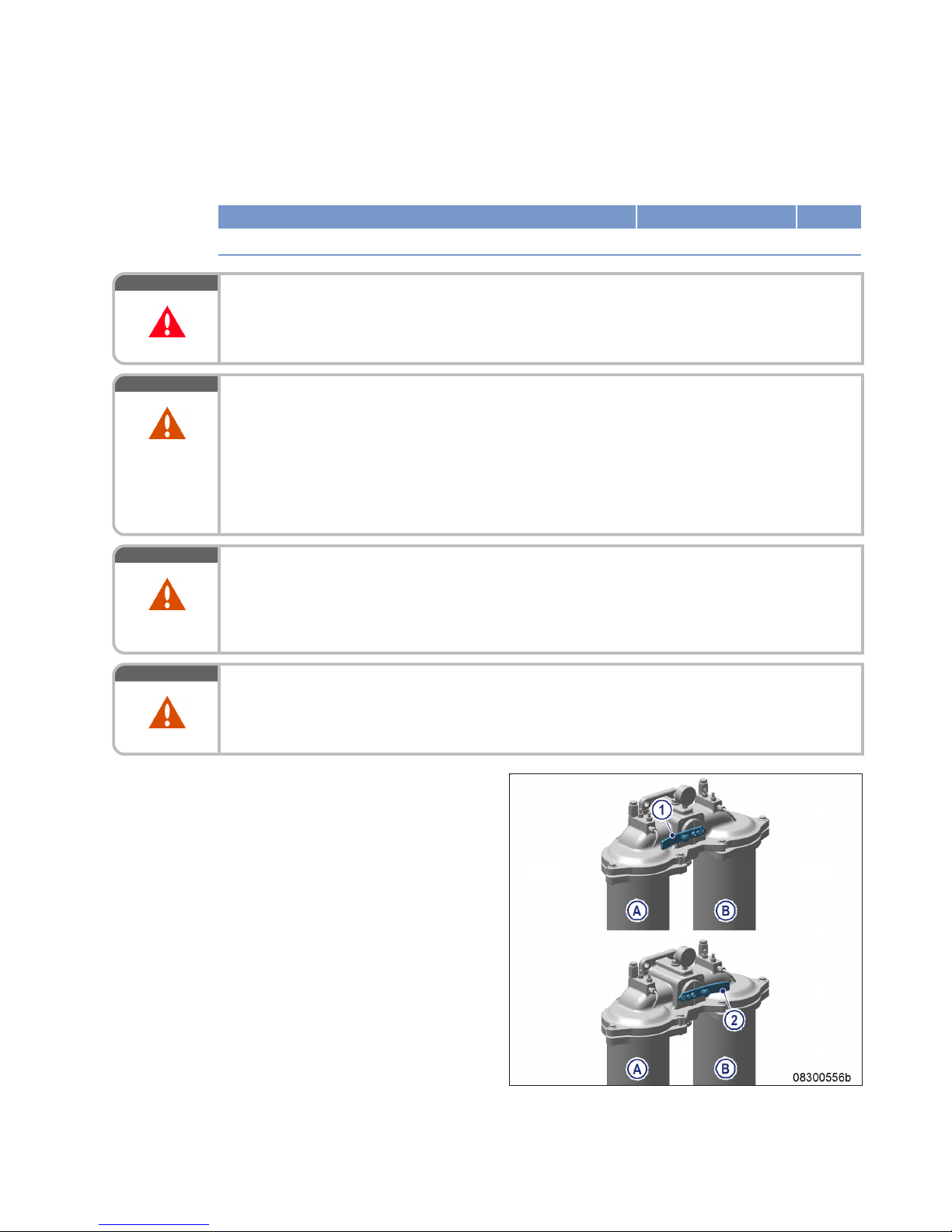
8.8.4 Fuel prefilter – Flushing
Special tools, Material, Spare parts
Designation / Use Part No. Qty.
Diesel fuel
DANGER
Rotating and moving engine parts.
Risk of crushing, danger of parts of the body being caught or pulled in!
• Only run the engine at low power. Keep away from the engine's danger zone.
WARNING
Liquid or gaseous media, e.g. fuel, are poisonous.
Escaping vapors of highly volatile media, e.g. fuel or ether.
Risk of fatal injury through swallowing; risk of poisoning through inhalation; irritation to eyes
and skin!
• Seek medical attention immediately; do not induce vomiting.
• Do not inhale vapors or mist.
• Wear protective clothing, protective gloves, and safety glasses.
• If contact is made with skin, wash off with water and soap.
WARNING
Fuels are combustible and explosive.
Risk of fire and explosion!
• Avoid open flames, electrical sparks and ignition sources.
• Do not smoke.
• Wear protective clothing, protective gloves, and safety glasses / facial protection.
WARNING
High level of engine noise when the engine is running.
Risk of damage to hearing!
• Wear ear protectors.
Fuel prefilter – Flushing
1. Cut out contaminated filter (A or B):
1 Filter A cut out
2 Filter B cut out
MW15409/04E 2015-08 | Task Description | 95
TIM-ID: 0000042959 - 005
Page 96
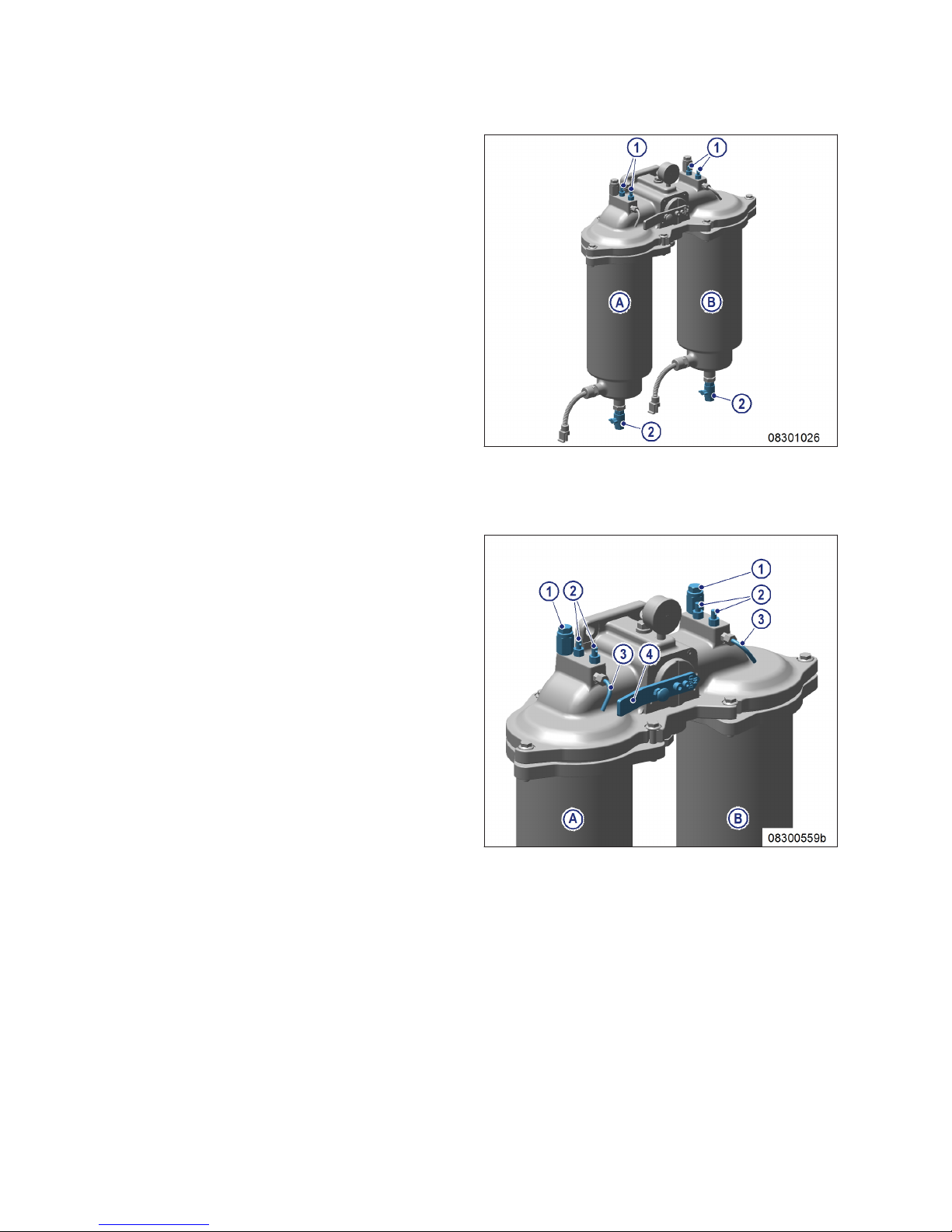
2. Open threaded vent plug (1) of filter to be
flushed.
3. Open drain valve (2) and drain fuel.
Result: Fuel flows from filtered side back to the unfil-
tered side, flushing the filter deposits downwards out of the filter.
4. Close threaded vent plug (1) and drain
valve (2).
Fuel prefilter, filling with fuel
1. Stop engine (→ Page 46) and disable engine start.
2. Connect filling pump to filling connection (1)
on the intake side of the filter.
3. Open vent valve (2) and fill with fuel until fuel
emerges from the vent pipe (3).
4. Close vent valve (2).
5. Open rotary slide valve (4) a little (by approx.
30°) and open vent valve(s) (2), until fuel
emerges from the vent pipe (3).
6. Close vent valve(s) (2).
7. Turn rotary slide valve (4) back to locked position.
8. Check differential pressure (→ Page 92).
Result: If flushing did not improve differential pres-
sure, replace filter element in fuel prefilter
(→ Page 97).
96 | Task Description | MW15409/04E 2015-08
TIM-ID: 0000042959 - 005
Page 97
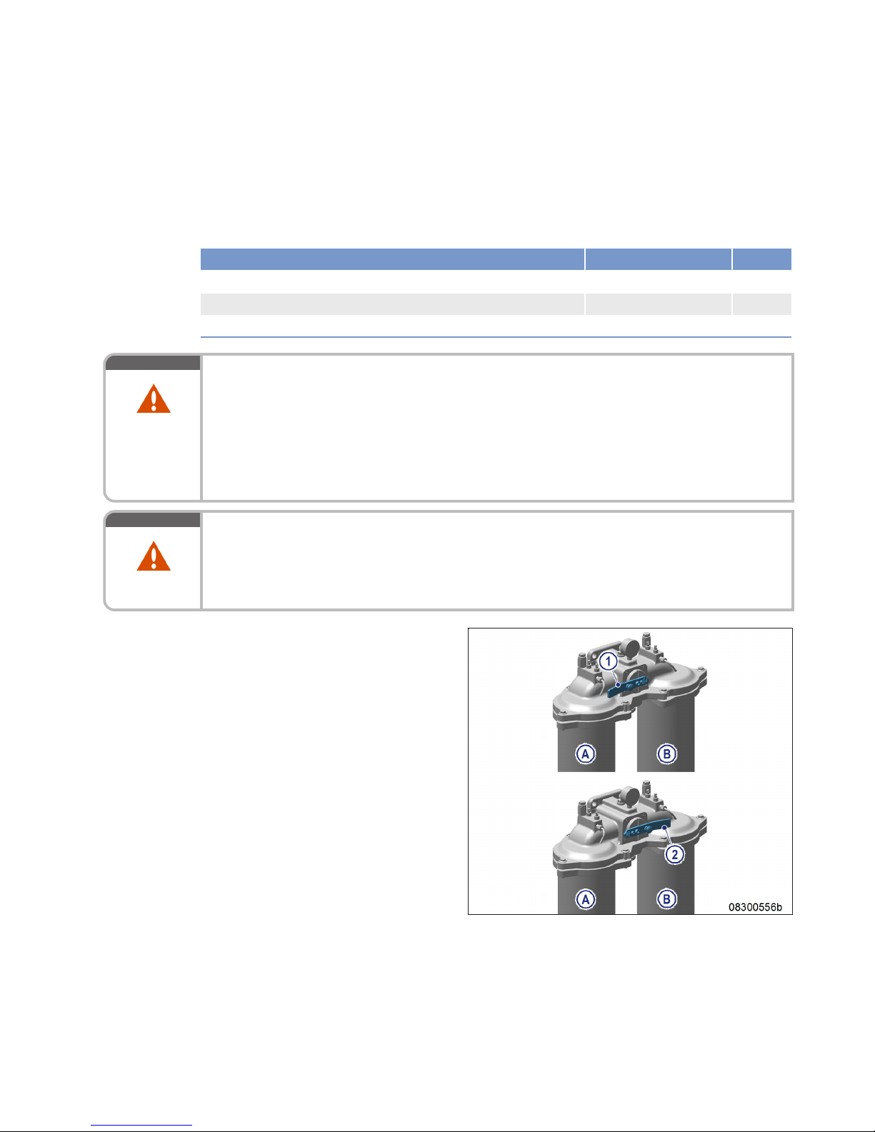
8.8.5 Fuel prefilter – Filter element replacement
Preconditions
☑ Engine is stopped and starting disabled.
Special tools, Material, Spare parts
Designation / Use Part No. Qty.
Diesel fuel
Filter element
(→ Spare Parts Catalog)
Gasket
(→ Spare Parts Catalog)
WARNING
Liquid or gaseous media, e.g. fuel, are poisonous.
Escaping vapors of highly volatile media, e.g. fuel or ether.
Risk of fatal injury through swallowing; risk of poisoning through inhalation; irritation to eyes
and skin!
• Seek medical attention immediately; do not induce vomiting.
• Do not inhale vapors or mist.
• Wear protective clothing, protective gloves, and safety glasses.
• If contact is made with skin, wash off with water and soap.
WARNING
Fuels are combustible and explosive.
Risk of fire and explosion!
• Avoid open flames, electrical sparks and ignition sources.
• Do not smoke.
• Wear protective clothing, protective gloves, and safety glasses / facial protection.
Replacing filter element
1. Cut out the filter to be replaced (A or B).
1 Filter A cut out
2 Filter B cut out
MW15409/04E 2015-08 | Task Description | 97
TIM-ID: 0000045554 - 004
Page 98
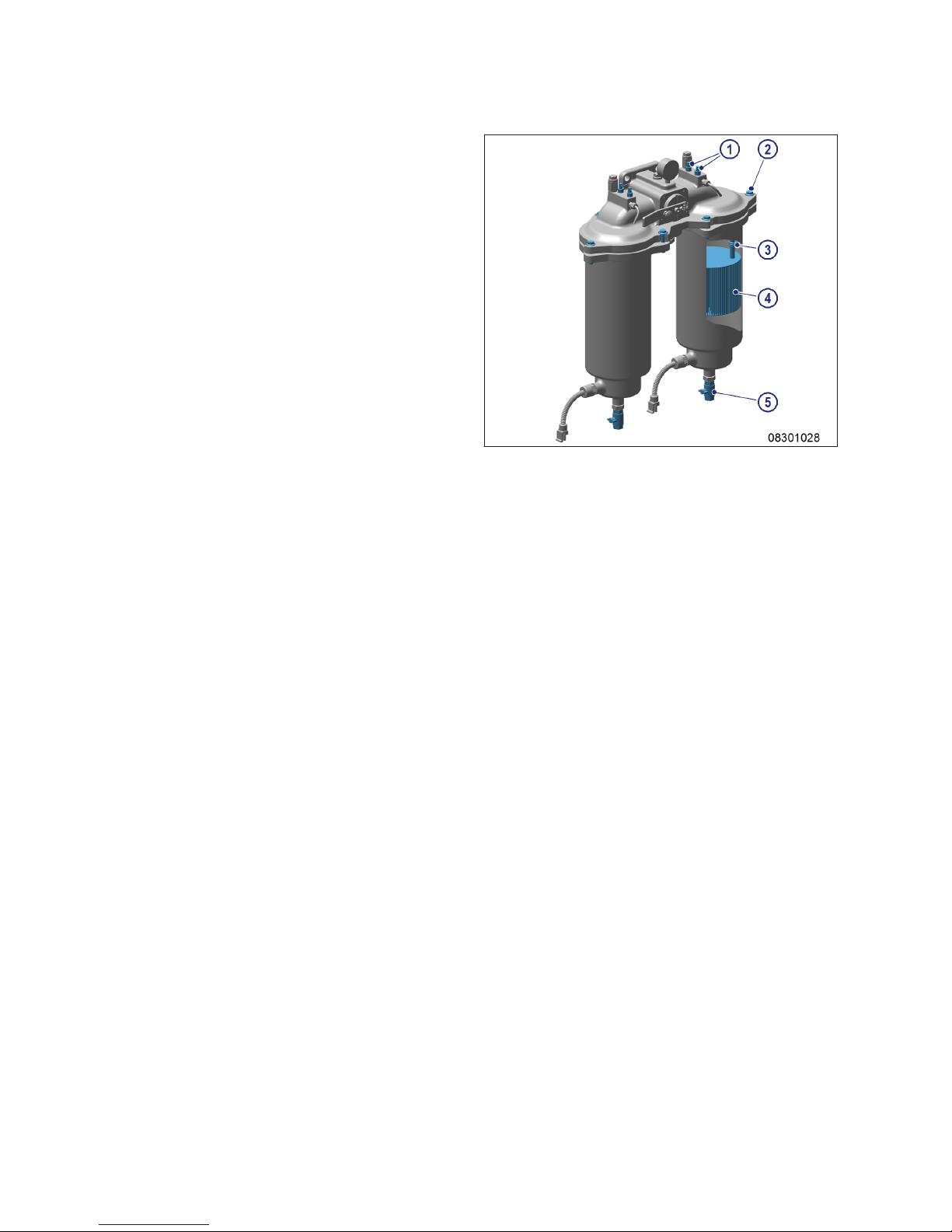
2. Open threaded vent plug (1) of contaminated
filter.
3. Unlock drain valve (5) by pressing toggle and
open it.
4. Drain water and dirt from filter.
5. Close drain valve (5).
6. Remove screws securing cover (2) and take
off cover.
7. Remove spring cartridge (3) and filter element (4).
8. Insert new filter element (4) and spring cartridge (3).
9. Fill filter housing with clean fuel.
10. Place new seal in cover.
11. Fit cover with gasket and secure it with
screws (2).
12. Cut in the cut-out filter again.
13. Close threaded vent plug (1) when fuel
emerges.
14. Set differential pressure display instrument
(→ Page 92).
98 | Task Description | MW15409/04E 2015-08
TIM-ID: 0000045554 - 004
Page 99

8.9 Sensors, Actuators and Injectors on the Engine
8.9.1 Sensors and actuators – Overview
Top view 12V 2000 M
1 B03 (intake air temperature)
2 B10 (charge-air pressure)
3 B09 (charge-air tempera-
ture)
4 B5.2 (lube oil pressure)
5 F25 (lube-oil pressure differ-
ence over filter)
6 B34 (fuel pressure after fil-
ter)
7 B07 (lube oil temperature)
8 B05 (lube oil pressure)
MW15409/04E 2015-08 | Task Description | 99
TIM-ID: 0000012937 - 004
Page 100
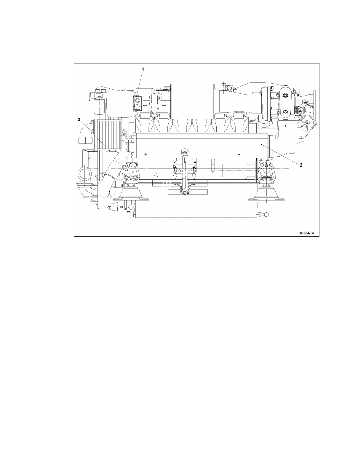
Left engine side 12V 2000 M
1 F33 (coolant level) 2 Y27 (turbocharger control
valve)
3 B21 (raw water pressure)
100 | Task Description | MW15409/04E 2015-08
TIM-ID: 0000012937 - 004
 Loading...