

Page 1

Operating Instructions
Diesel engine
12 V 2000 M84
16 V 2000 M84
MS150063/02E
Page 2

Engine model kW/cyl. Application group
12V2000M84 101.7 kW/cyl. 1D, Continuous operation, variable, medium load
factors
16V2000M84 101.9 kW/cyl. 1D, Continuous operation, variable, medium load
factors
Table 1: Applicability
Printed in Germany
© 2014 Copyright MTU Friedrichshafen GmbH
This publication is protected by copyright and may not be used in any way, whether in whole or in part, without the prior
written consent of MTU Friedrichshafen GmbH. This particularly applies to its reproduction, distribution, editing, translation, microfilming and storage or processing in electronic systems including databases and online services.
All information in this manual was the latest information available at the time of going to print. MTU Friedrichshafen
GmbH reserves the right to change, delete or supplement the information provided as and when required.
Page 3

Table of Contents
1 Safety
1.1 Important requirements for all products 5
1.2 Personnel and organizational requirements 6
1.3 Transport 7
1.4 Safety requirements for startup and
operation 9
1.5 Safety requirements for maintenance and
repair work 10
1.6 Fire prevention and environmental
protection, fluids and lubricants, auxiliary
materials 13
1.7 Standards for safety notices in the text 15
2 General Information
2.1 Tightening specifications for screws, nuts
and bolts 16
2.2 Engine side and cylinder designations 27
2.3 Product description 28
2.4 Engine layout 34
2.5 Sensors and actuators – Overview 36
3 Technical Data
3.1 12V 2000 M84 engine data 41
3.2 16V 2000 M84 engine data 44
3.3 Firing order 47
3.4 Engine – Main dimensions 48
4 Operation
4.1 Putting the engine into operation after
extended out-of-service periods (>3 months) 49
4.2 Engine – Putting into operation after
scheduled out-of-service-period 50
4.3 Tasks after extended out-of-service periods
(>3 weeks) 51
4.4 Checks prior to start-up 52
4.5 Fuel treatment system – Putting into
operation 53
4.6 Operational checks 55
4.7 Fuel treatment system – Switching on 56
4.8 Starting the engine 57
4.9 Engine – Shutdown 58
4.10 Emergency engine stop 59
4.11 After stopping the engine 60
4.12 Fuel treatment system – Shutdown 61
4.13 Plant – Cleaning 62
5 Maintenance
5.1 Maintenance task reference table [QL1] 63
6 Troubleshooting
6.1 Fuel treatment system – Troubleshooting 64
6.2 Troubleshooting 65
7 Task Description
7.1 SOLAS 68
7.1.1 SOLAS shielding as per MTN 5233 –
Installation 68
7.1.2 SOLAS shielding – Installation 69
7.1.3 Installation locations for SOLAS shielding 70
7.2 Engine 75
7.2.1 Engine – Barring manually 75
7.2.2 Engine – Cranking on starting system 76
7.3 Cylinder Liner 77
7.3.1 Cylinder liner – Endoscopic examination 77
7.3.2 Instructions and comments on endoscopic and
visual examination of cylinder liners 79
7.4 Crankcase Breather 81
7.4.1 Crankcase breather – Cleaning oil preseparator element 81
7.4.2 Crankcase breather – Oil separator element
replacement, diaphragm check and
replacement 82
7.5 Valve Drive 84
7.5.1 Valve clearance – Check and adjustment 84
7.5.2 Cylinder head cover – Removal and
installation 86
7.6 Injection Valve / Injector 87
7.6.1 Injector – Replacement 87
7.6.2 Injector – Removal and installation 88
7.7 Fuel System 90
7.7.1 Fuel system – Venting 90
7.8 Fuel Filter 91
7.8.1 Fuel filter – Replacement 91
7.8.2 Fuel prefilter – Differential pressure check
and adjustment of gauge 93
7.8.3 Fuel prefilter – Draining 94
7.8.4 Fuel prefilter – Flushing 96
7.8.5 Fuel prefilter – Filter element replacement 98
7.9 Charge-Air Cooling 100
7.9.1 Intercooler – Checking condensate drain line
for coolant discharge and obstruction 100
7.10 Air Filter 101
MS150063/02E 2014-03 | Table of Contents | 3
DCL-ID: 0000016266 - 002
Page 4

7.10.1 Air filter – Replacement 101
7.10.2 Air filter – Removal and installation 102
7.11 Air Intake 103
7.11.1 Service indicator – Signal ring position check
(optional) 103
7.12 Starting Equipment 104
7.12.1 Starter – Condition check 104
7.13 Lube Oil System, Lube Oil Circuit 105
7.13.1 Engine oil – Level check 105
7.13.2 Engine oil – Change 106
7.14 Oil Filtration / Cooling 107
7.14.1 Engine oil filter – Replacement 107
7.14.2 Centrifugal oil filter and filter sleeve –
Cleaning and replacement 109
7.15 Coolant Circuit, General, High-Temperature
Circuit 112
7.15.1 Drain and venting points 112
7.15.2 Engine coolant – Level check 117
7.15.3 Engine coolant – Change 118
7.15.4 Engine coolant – Draining 119
7.15.5 Engine coolant – Filling 120
7.15.6 HT coolant pump – Relief bore check 121
7.15.7 Engine coolant – Sample extraction and
analysis 122
7.15.8 Coolant filter – Replacement 123
7.16 Raw Water Pump with Connections 124
7.16.1 Raw water pump – Relief bore check 124
7.17 Belt Drive 125
7.17.1 Drive belt – Condition check 125
7.18 Battery-Charging Generator 126
7.18.1 Battery-charging generator drive – Drive belt
replacement 126
7.19 Fuel Supply System 127
7.19.1 Water drain valve – Check 127
7.19.2 Differential pressure gauge – Check 128
7.19.3 Water level probe (3-in-1 rod electrode) –
Check 129
7.19.4 Pump capacity – Check 130
7.19.5 Coalescer filter element – Replacement 131
7.20 Wiring (General) for Engine/Gearbox/Unit 133
7.20.1 Engine wiring – Check 133
7.21 Accessories for (Electronic) Engine
Governor / Control System 134
7.21.1 Engine governor and connectors – Cleaning 134
7.21.2 EMU and connectors – Cleaning 135
7.21.3 Engine governor plug connections – Check 136
7.21.4 Engine Monitoring Unit EMU 7 – Plug
connection check 137
7.21.5 Interface module EIM plug connections –
Check 138
7.21.6 Engine Control Unit – Self-test 139
7.21.7 Engine Control Unit ECU 7 – Removal and
installation 140
7.21.8 Engine Monitoring Unit – Removal and
installation 141
7.21.9 Engine Interface Module EIM – Removal and
installation 142
7.21.10 Diagnostic features of EIM 143
8 Appendix A
8.1 Abbreviations 146
8.2 MTU contact persons/service partners 148
9 Appendix B
9.1 Special Tools 149
9.2 Index 156
4 | Table of Contents | MS150063/02E 2014-03
DCL-ID: 0000016266 - 002
Page 5

1 Safety
1.1 Important requirements for all products
Nameplate
The product is identified by a nameplate, model designation or serial number which must match the
information on the title page of this manual.
Nameplate, model designation or serial number can be found on the product.
General information
This product may pose a risk of injury or damage in the following cases:
• Improper use
• Operation, maintenance and repair by unqualified personnel
• Changes or modifications
• Noncompliance with the safety instructions and warning notices
Intended use
The product is intended for use in accordance with its contractually-defined purpose as described in the
relevant technical documents only.
Intended use entails operation:
• Within the permissible operating parameters in accordance with the (→ Technical data)
• With fluids and lubricants approved by the manufacturer in accordance with the (→ Fluids and Lubricants Specifications of the manufacturer)
• With spare parts approved by the manufacturer in accordance with the (→ Spare Parts Catalog/MTU
contact/Service partner)
• In the original as-delivered configuration or in a configuration approved by the manufacturer in writing (including engine management/parameters)
• In compliance with all safety regulations and in accordance with all warning notices in this manual
• With maintenance work performed in accordance with the (→ Maintenance Schedule) throughout the
useful life of the product
• In compliance with the maintenance and repair instructions contained in this manual, in particular
with regard to the specified tightening torques
• With the exclusive use of technical personnel trained in commissioning, operation, maintenance and
repair
• By contracting only workshops authorized by the manufacturer to carry out repair and overhaul
Any other use shall be considered non-intended. Such improper use increases the risk of injury and
damage when working with the product. The manufacturer shall not be held liable for any damage resulting from improper, non-intended use.
Changes or modifications
Unauthorized changes to the product represent a contravention of its intended use and compromise
safety.
Changes or modifications shall only be considered to comply with the intended use when expressly authorized by the manufacturer. The manufacturer shall not be held liable for any damage resulting from
unauthorized changes or modifications.
MS150063/02E 2014-03
| Safety | 5
TIM-ID: 0000040530 - 004
Page 6

1.2 Personnel and organizational requirements
Organizational measures of the operator
This manual must be issued to all personnel involved in operation, maintenance, repair or transportation.
Keep this manual handy in the vicinity of the product such that it is accessible to operating, maintenance, repair and transport personnel at all times.
Use this manual as a basis for instructing personnel on product operation and repair, whereby the safety-relevant instructions, in particular, must be read and understood.
This is particularly important in the case of personnel who only occasionally perform work on or around
the product. This personnel must be instructed repeatedly.
Personnel requirements
All work on the product shall be carried out by trained and qualified personnel only.
• Training at the Training Center of the manufacturer
• Qualified personnel specialized in mechanical and plant engineering
The operator must define the responsibilities of the personnel involved in operation, maintenance, repair and transport.
Working clothes and personal protective equipment
Wear proper protective clothing for all work.
When working, always wear the necessary personal protective equipment (e.g. ear protectors, protective gloves, goggles, breathing protection). Observe the information on personal protective equipment
in the respective activity description.
6 | Safety | MS150063/02E 2014-03
TIM-ID: 0000040531 - 002
Page 7
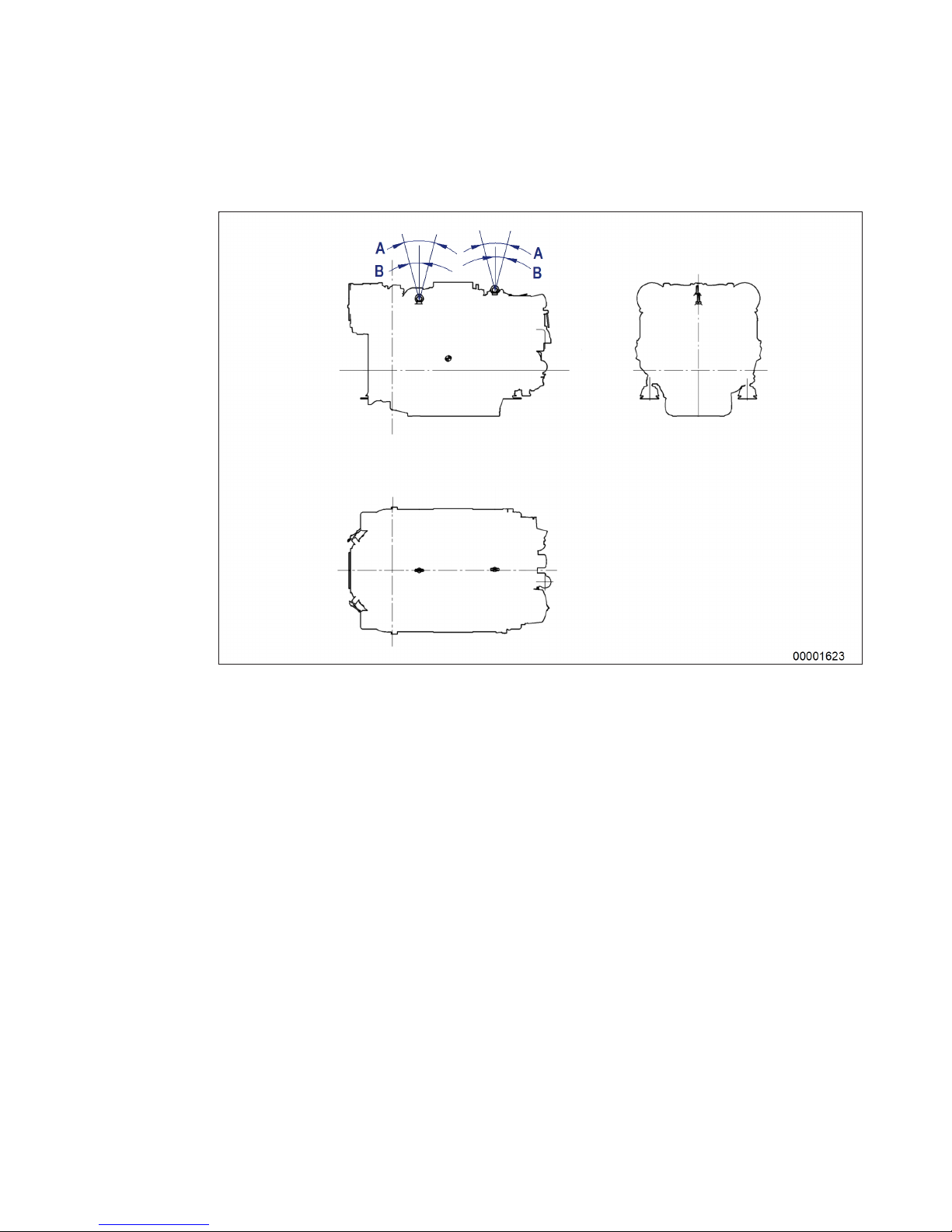
1.3 Transport
Transport without flange-mounted gearbox
A max. permissible diagonal
pull 70°
B max. permissible diagonal
pull 35°
Illustration is valid for 12/16V 2000 M engines
MS150063/02E 2014-03 | Safety | 7
TIM-ID: 0000038133 - 001
Page 8

Transport with flange-mounted gearbox
Illustration is valid for 12/16V 2000 M engines
Lift the engine only with the lifting eyes provided.
The eyebolts mounted at the driving end and on the gearbox must not be used for transporting plants
with flange-mounted gearboxes.
Only use transport and lifting devices approved by MTU.
Take the engine's center of gravity into account.
The engine must only be transported in installation position, max. permissible diagonal pull with flangemounted gearbox is 10°.
If the engine is supplied with special aluminum foil packing, lift the engine at the lifting eyes of the bearing pedestal or use a means of transportation which is appropriate for the given weight (forklift truck).
Install the crankshaft locking device and the locking screws for the engine mounts prior to engine transportation.
Secure the engine against tilting during transport. In particular when going down inclines or ramps, the
engine must be secured against moving and tilting.
Setting the engine down after transport
Only set down engine on a firm, level surface.
Make sure that the consistency and load-bearing capacity of the ground or support surface is adequate.
Never set an engine down on the oil pan unless expressively authorized to do so by MTU on a case-tocase basis.
8 | Safety |
MS150063/02E 2014-03
TIM-ID: 0000038133 - 001
Page 9

1.4 Safety requirements for startup and operation
Safety requirements for startup
The product must be installed and accepted in accordance with manufacturers' specifications prior to
initial startup.
All the requisite regulatory approvals must have been granted and all startup requirements fulfilled prior
to initial startup.
Whenever the product is started, always ensure that:
• All maintenance and repair work has been completed.
• All loose parts have been removed from rotating machine components.
• Wearers of cardiac pacemakers or other active medical implants are well clear.
• The operating room is adequately ventilated.
• Exhaust pipework is leak-tight and routed to atmosphere.
• Battery terminals, generator terminals and cables are guarded to preclude accidental contact.
• All personnel is clear of the danger zone represented by moving parts.
Immediately after putting the product into operation, make sure that all control and display instruments
as well as the monitoring, signaling and alarm systems are working properly.
Safety requirements for operation
The operator must be familiar with the controls and displays.
The operator must be aware of the consequences of any operations he/she performs.
During operation, the display instruments and monitoring units must be constantly observed in regard
of present operating status, limit value violation and warning or alarm messages.
Malfunctions and emergency stop
Emergency procedures, in particular emergency stop, must be practiced on a regular basis.
Take the following steps if a system malfunction is detected or signaled by the system:
• Inform the duty supervisor(s).
• Evaluate the message.
• Respond to the emergency appropriately, e.g. execute an emergency stop.
Operation
Do not stay in the operating room when the product is running unless absolutely necessary and then as
briefly as possible.
Keep a safe distance away from the product whenever possible. Do not touch the product unless expressly instructed to do so.
Do not inhale exhaust gases emitted by the product.
Ensure that the following requirements have been fulfilled before starting the product:
• Ear protectors are worn.
• Mop up any leaked or spilled fluids and lubricants immediately or soak up with a suitable binding
agent.
Operation of electrical equipment
Some components are live (high voltage) when electrical equipment is in operation.
Observe the safety instructions for these appliances.
MS150063/02E 2014-03
| Safety | 9
TIM-ID: 0000040533 - 005
Page 10

1.5 Safety requirements for maintenance and repair work
Safety requirements before commencing maintenance and repair work
Have maintenance or repair work carried out by qualified and authorized personnel only.
Allow the product to cool down to less than 50°C (risk of explosion for oil vapors, fluids and lubricants,
risk of burning).
Relieve pressure in fluid and lubricant systems and compressed-air lines which are to be opened. Use
suitable collection vessels with a sufficient filling volume.
Ensure that the operating room is adequately ventilated when changing the oil or working on the fuel
system.
Do not perform maintenance or repair work when the product is running unless:
• expressly instructed to do so.
• the product is running in the low load range and only for as long as necessary to complete the task.
Lock-out the product to preclude undesired starting, e.g. start interlock.
Tag-out the product with a “Do Not Start” sign in the operation room or on the control facility.
Disconnect the battery. Lock the contactor.
Close the main valve on the compressed-air system and vent the compressed-air line when pneumatic
starters are fitted.
Disconnect the control facility from the product.
For starters with pinions made of copper-beryllium alloy:
• Wear a respirator mask (filter class P3). Do not blow out the interior of the flywheel housing or the
starter with compressed air. Clean the interior of the flywheel housing with a class H dust extractor.
• Observe the safety data sheet.
Safety requirements during maintenance and repair work
Take special care when removing vent plugs or plug screws from the product. Hold a cloth over the
screw or plug to prevent discharge of highly pressurized liquids.
Take care when draining hot fluids and lubricants (risk of burning).
Use suitable and calibrated tools only. Observe the specified tightening torques during assembly or disassembly.
Carry out work only on assembles and/or installations which are properly secured.
Never climb up on the lines.
Keep fuel injection lines and connections clean.
Always seal connections with caps or covers if a line is removed or opened.
Fit new seals when re-installing lines.
Avoid damaging lines, particularly the fuel lines.
Ensure that all retainers and dampers are installed correctly.
Ensure that all fuel injection and pressurized oil lines are installed with enough clearance to prevent
contact with other components. Never route fuel or oil lines in the vicinity of hot components.
Do not touch elastomeric seals (e.g. Viton sealing rings) with your bare hands if they have a carbonized
or resinous appearance.
Observe the cooling time for components which have been heated for installation or removal (risk of
burning!).
Always use suitable ladders and work platforms when working above head-height. Ensure that components or assemblies are placed on stable surfaces.
10 | Safety |
MS150063/02E 2014-03
TIM-ID: 0000040535 - 005
Page 11

Pay particular attention to cleanliness at all times.
Safety requirements after completing maintenance and repair work
Ensure that all personnel is clear of danger zones before cranking.
Check that all access ports/apertures which have been opened to facilitate working are closed again.
Check that all safety equipment has been installed and that all tools and loose parts have been removed (especially the barring gear).
Ensure that no unattached parts have been left in/on the product (e.g. including rags and cable straps).
Welding work
Do not perform welding on the product or its attachments. Cover the product when performing welding
work in the vicinity.
Before commencing welding work:
• Switch off the master power supply switch.
• Disconnect the battery.
• Disconnect electronic and genset grounds.
Do not perform maintenance or repair work on the product when welding is in progress in its vicinity.
Risk of explosion or fire due to oil vapors and highly flammable process materials.
Do not use the product as a grounding terminal.
Do not route the welding cable over or near the wiring harnesses of the product. The welding current
may otherwise induce an interference voltage in the wiring harnesses which could conceivably damage
the electrical system.
Remove components (e.g. exhaust pipe) from the product before performing necessary welding work .
Hydraulic installation and removal
Check function and satisfactory condition of the jigs and fixtures to be used. Use only the specified jigs
and fixtures for hydraulic removal/installation.
Observe the max. permissible force-on pressure specified for the installation/removal jig.
Do not attempt to bend or exert force on HP lines.
Before starting work, pay attention to the following:
• Vent the installation/removal jig, the pumps and the pipework at the relevant designated points.
• For hydraulic installation, screw on the jig with the piston retracted.
• For hydraulic removal, screw on the jig with the piston extended.
For hydraulic installation/removal jigs with central expansion pressure supply, screw the spindle into
the shaft end until correct sealing has been established.
During hydraulic installation and removal, ensure that nobody is standing in the immediate vicinity of
the component to be installed/removed.
Working with batteries
Observe the safety requirements of the battery manufacturer when working with batteries.
Gases released from the battery are explosive. Avoid sparks and naked flames.
Do not allow electrolyte (battery acid) to come into contact with skin or clothing.
Wear goggles and protective gloves.
Do not place tools on the battery.
Check polarity before connecting the cable to the battery. Battery polarity reversal may lead to injury by
the sudden discharge of acid or bursting of the battery unit.
MS150063/02E 2014-03
| Safety | 11
TIM-ID: 0000040535 - 005
Page 12

Working on electrical/electronic assemblies
Always obtain the permission of the duty supervisor before commencing maintenance or repair work or
switching off any part of the electronic system required to do so.
De-energize the appropriate areas prior to working on assemblies.
Avoid damaging cabling during removal. When reconnecting, ensure that cabling cannot be damaged
during operation by:
• Contact with sharp edges
• Chafing on components
• Contact with hot surfaces.
Do not secure cabling to lines bearing fluids.
Do not use cable ties to secure cabling.
Always use connector pliers to tighten union nuts on connectors.
Subject the device and also the product to appropriate function testing whenever repair work has been
completed. In particular, check the function of the emergency stop feature.
Store spare parts properly prior to replacement, i.e. protect them against moisture in particular. Package faulty electronic components or assemblies properly before dispatching for repair:
• Moisture-proof
• Shock-proof
• Wrapped in antistatic foil if necessary.
Working with laser equipment
Always wear special laser-protection goggles when working with laser equipment (danger due to intensely focused radiation).
Laser equipment must be fitted with the protective devices necessary for safe operation according to
type and application.
For conducting light-beam procedures and measurement work, only the following laser devices must be
used:
• Laser devices of classes 1, 2 or 3A.
• Laser devices of class 3B, which have maximum output in the visible wavelength range (400 nm to
700 nm), a maximum output of 5 mW, and in which the beam axis and surface are designed to prevent any risk to the eyes.
Measuring component deviations
Workpieces, components and measuring instruments are within specified tolerances at a reference
temperature of 20°C.
12 | Safety | MS150063/02E 2014-03
TIM-ID: 0000040535 - 005
Page 13

1.6 Fire prevention and environmental protection, fluids and
lubricants, auxiliary materials
Fire prevention
Rectify any fuel or oil leaks immediately. Oil or fuel on hot components can cause fires – therefore always keep the product in a clean condition. Do not leave rags saturated with fluids and lubricants on
the product. Do not store combustible materials near the product.
Do not carry out welding work on pipes and components carrying oil or fuel. Before welding, clean with
a nonflammable fluid.
When starting the engine with an external power source, connect the ground lead last and remove it
first. To avoid sparks in the vicinity of the battery, connect the ground lead from the external power
source to the ground lead of the engine or to the ground terminal of the starter.
Always keep suitable firefighting equipment (fire extinguishers) at hand and familiarize yourself with
their use.
Noise
Noise can lead to an increased risk of accidents if it makes it more difficult to hear audible signals,
warning calls or noises indicating danger.
Wear ear protectors in workplaces with a sound pressure level in excess of 85dB (A).
Environmental protection and disposal
Modification or removal of any mechanical/electronic components or the installation of additional components including the execution of calibration processes that might affect the emission characteristics
of the product are prohibited by emission regulations. Emission control units/systems may only be
maintained, exchanged or repaired if the components used for this purpose are approved by the manufacturer. Noncompliance with these guidelines will invalidate the design type approval issued by the
emissions regulation authorities. The manufacturer does not accept any liability for violations of the
emission regulations. The maintenance schedules of the manufacturer must be observed over the entire
life cycle of the product.
Dispose of used fluids, lubricants and filters in accordance with local regulations.
Within the EU, batteries can be returned free of charge to the manufacturer where they will be properly
recycled.
Fluids and lubricants and auxiliary materials
The Fluids and Lubricants Specifications will be amended or supplemented as necessary. Prior to operation, make sure that the latest version is used. The latest version can be found on the website on the
"Technical Info" or "Spare Parts and Service" tabs at http://www.mtu-online.com.
Consumable fluids and materials may also be hazardous or toxic. When using fluids, lubricants, consumables and other chemical substances, follow the safety regulations that apply to the product. Take special care when using hot, chilled or caustic substances. When using flammable materials, prevent them
coming into contact with ignition sources and do not smoke.
Used oil
Used oil contains combustion residues that are harmful to health.
Rub barrier cream into hands.
Wash hands after contact with used oil.
MS150063/02E 2014-03
| Safety | 13
TIM-ID: 0000040536 - 005
Page 14

Lead
• Adopt suitable measures to avoid the formation of lead dust.
• Switch on extraction system.
• When working with lead or pastes that contain lead, avoid direct contact with the skin. Do not inhale
lead vapors.
• Wash hands after contact with lead or lead-containing substances.
Compressed air
Observe special safety precautions when working with compressed air:
• Unauthorized use of compressed air, e.g. forcing flammable liquids (hazard class AI, AII and B) out of
containers, risks causing an explosion.
• Wear goggles when blowing dirt off workpieces or blowing away swarf.
• Blowing compressed air into thin-walled containers (e.g. containers made of sheet metal, plastic or
glass) for drying purposes or to check for leaks risks bursting them.
• Pay special attention to the pressure in the compressed air system or pressure vessel.
• Assemblies or products to be connected must either be designed for that pressure, or, if the permissible pressure is lower than the system pressure, a pressure reducing valve and safety valve (set to
the permissible pressure) must be connected between the assemblies/products and the system.
• Hose couplings and connections must be securely attached.
• Provide the snout of the air nozzle with a protective disk (e.g. rubber disk).
• First shut off compressed air lines before compressed air device is disconnected from the supply
line, or before device or tool is to be replaced.
• Carry out leak test in accordance with the specifications.
Paints and varnishes
• Observe the relevant safety data sheet for all materials.
• When painting in areas other than spray booths equipped with extractors, ensure good ventilation.
Make sure that neighboring work areas are not adversely affected.
• There must be no naked flames in the vicinity.
• No smoking.
• Observe fire prevention regulations.
• Always wear a mask providing protection against paint and solvent vapors.
Liquid nitrogen
• Observe the relevant safety data sheet for all materials.
• Work with liquid nitrogen may be carried out only by qualified personnel.
• Store liquid nitrogen only in small quantities and always in regulation containers (without gas-tight
caps).
• Avoid body contact (eyes, hands).
• Wear protective clothing, protective gloves, closed shoes and safety goggles.
• Make sure that working area is well ventilated.
• Avoid knocking or jolting the containers, valves and fittings or workpieces in any way.
Acids/alkaline solutions/urea (AdBlue®, DEF)
• Observe the relevant safety data sheet for all materials.
• When working with acids and alkaline solutions, wear goggles or face mask, gloves and protective
clothing.
• Do not inhale vapors.
• If urea solution is swallowed, rinse out mouth and drink plenty of water.
• If spilled onto clothing, remove the affected clothing immediately.
• After contact with skin, rinse affected parts of the body with plenty of water.
• Rinse eyes immediately with eye drops or clean tap water. Seek medical attention as soon as possible.
14 | Safety |
MS150063/02E 2014-03
TIM-ID: 0000040536 - 005
Page 15

1.7 Standards for safety notices in the text
DANGER
In the event of immediate danger.
Consequences: Death, serious or permanent injury!
• Remedial action.
WARNING
In the event of a situation involving potential danger.
Consequences: Death, serious or permanent injury!
• Remedial action.
CAUTION
In the event of a situation involving potential danger.
Consequences: Minor or moderate injuries!
• Remedial action.
NOTICE
In the event of a situation involving potentially adverse effects on the product.
Consequences: Material damage!
• Remedial action.
• Additional product information.
Safety notices
1. This manual with all safety instructions and safety notices must be issued to all personnel involved in
operation, maintenance, repair or transportation.
2. The higher level warning notice is used if several hazards apply at the same time. Warnings related to
personal injury shall be considered to include a warning of potential damage.
MS150063/02E 2014-03 | Safety | 15
TIM-ID: 0000040578 - 003
Page 16

2 General Information
2.1 Tightening specifications for screws, nuts and bolts
Tightening torques for setscrew and stud joints to MTN 5008 standard
This standard applies to setscrews not subject to dynamic loads and the associated nuts according to:
• MMN 384
• DIN 912
• ISO 4014 (DIN 931-1)
• ISO 4017 (DIN 933)
• EN 28765 (DIN 960)
• EN 28676 (DIN 961)
• DIN 6912
This standard applies to studs not subject to dynamic loads and the associated nuts according to:
• DIN 833
• DIN 835
• DIN 836
• DIN 938
• DIN 939
The standard does not apply to heat-resistant screws in the hot component zone.
Tightening torques MA are specified for screws of strength class 8.8 (surface finish bare metal, phosphatized or galvanized) and 10.9 (surface finish bare metal or phosphatized).
The values in the table are based on a friction coefficient µtot = 0.125.
Threads and mating faces of screws and nuts must be coated with engine oil prior to assembly.
When hand-tightening (defined torque), an assembly tolerance of +10% of the figures in the table is permitted.
When machine-tightening, the permissible assembly tolerance is ±15%.
Thread
Hand-tightening Machine-tightening
8.8 MA (Nm) 10.9 MA (Nm) 8.8 MA (Nm) 10.9 MA (Nm)
M6 9 12 8 11
M8 21 31 20 28
M8 x 1 23 32 21 30
M10 42 60 40 57
M10 x 1.25 45 63 42 60
M12 74 100 70 92
M12 x 1.25 80 110 75 105
M12 x 1.5 76 105 72 100
M14 115 160 110 150
M14 x 1.5 125 180 120 170
M16 180 250 170 235
M16 x 1.5 190 270 180 255
M18 250 350 240 330
M18 x 1.5 280 400 270 380
M20 350 500 330 475
M20 x 1.5 390 550 350 520
16 | General Information | MS150063/02E 2014-03
TIM-ID: 0000002333 - 015
Page 17

Thread
Hand-tightening Machine-tightening
8.8 MA (Nm) 10.9 MA (Nm) 8.8 MA (Nm) 10.9 MA (Nm)
M22 480 680 450 650
M22 x 1.5 520 730 490 700
M24 600 850 570 810
M24 x 1.5 680 950 640 900
M24 x 2 660 900 620 850
M27 900 1250 850 1175
M27 x 2 960 1350 900 1275
M30 1200 1700 1100 1600
M30 x 2 1350 1900 1250 1800
MA= tightening torques
Tightening torques for stress bolt connections to MTN 5007 standard
This standard applies to stress pin bolts and stress bolts which are subjected to static and dynamic
load of strength class 10.9 as well as to the associated nuts.
Shank and junction dimensions to MMN 209 standard and material and manufacture to MMN 389
standard (bare metal or phosphatized).
The values in the table are based on a friction coefficient µtot = 0.125.
Threads and mating faces of screws and nuts must be coated with engine oil prior to assembly.
An assembly tolerance of +10% of the figures in the table is permitted due to unavoidable deviations
during the tightening process.
The figures in the table are for hand-tightening using a torque wrench.
Thread
Not torsion-protected MA(Nm) Torsion-protected MA(Nm)
M6 9 12
M8 21 28
M8 x 1 24 30
M10 42 55
M10 x 1.25 46 60
M12 75 93
M12 x 1.5 78 99
M14 120 150
M14 x 1.5 135 160
M16 180 225
M16 x 1.5 200 245
M18 250 315
M18 x 1.5 300 360
M20 350 450
M20 x 1.5 430 495
M22 500 620
M22 x 1.5 560 675
M24 640 790
M24 x 2 700 850
MS150063/02E 2014-03 | General Information | 17
TIM-ID: 0000002333 - 015
Page 18
Thread
Not torsion-protected MA(Nm) Torsion-protected MA(Nm)
M27 900 1170
M27 x 2 1000 1230
M30 1250 1575
*Protect screw shaft from torsion when tightening.
MA= tightening torques
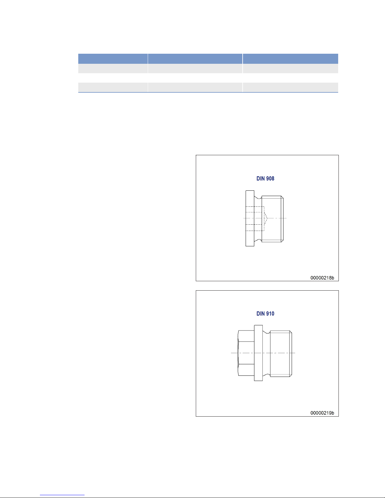
Tightening torques for plug screws to MTN 5183-1 standard
This standard applies to plug screws to DIN 908, DIN 910 and DIN 7604 with threaded end to DIN 3852
Form A (sealed with sealing ring to DIN 7603-Cu).
18 | General Information | MS150063/02E 2014-03
TIM-ID: 0000002333 - 015
Page 19
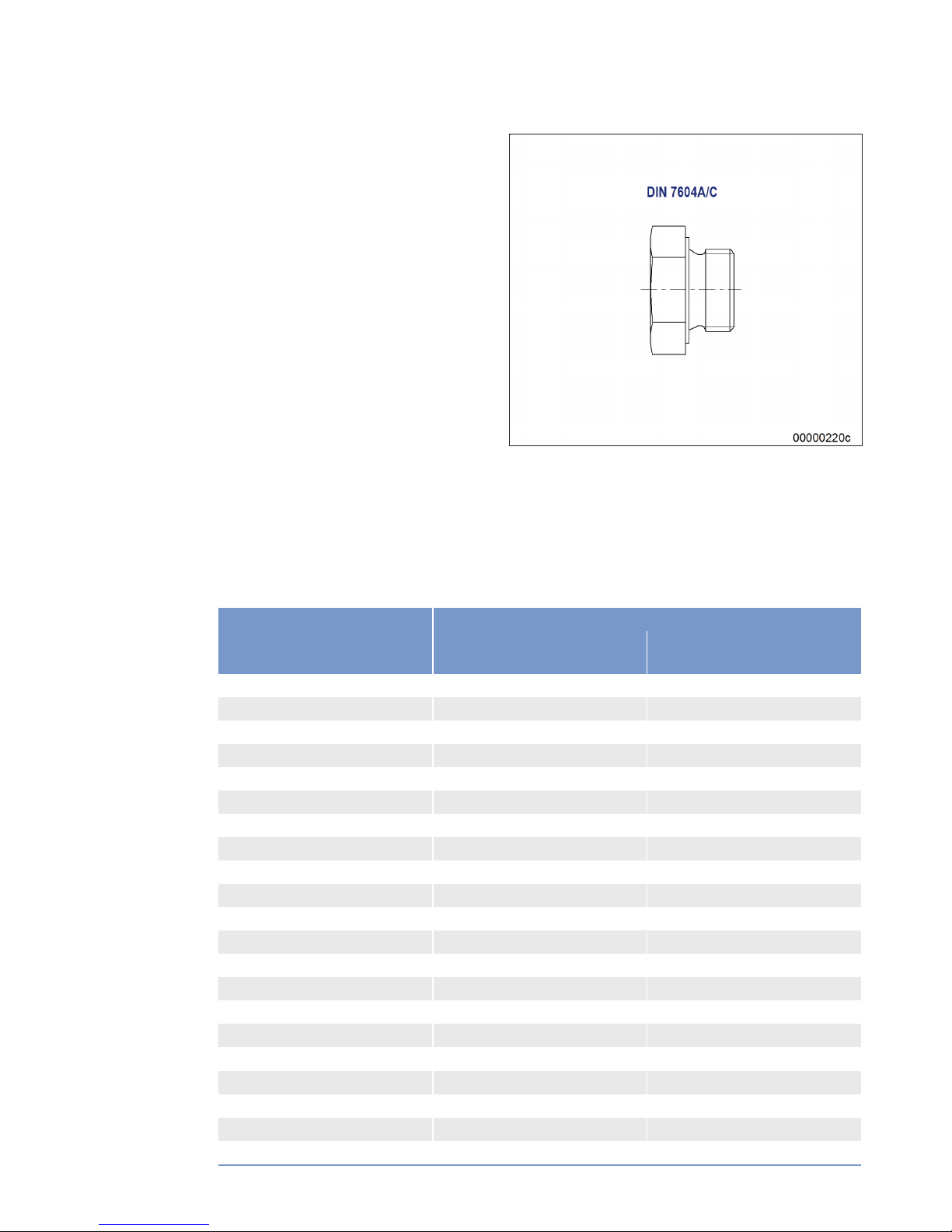
Tightening torques MA are given for screw plugs made of steel (St) with surface protected by a phosphate coating and oiled or galvanized.
Threads and mating faces beneath heads must be coated with engine oil prior to assembly.
An assembly tolerance of +10% of the figures in the table is permitted due to unavoidable deviations
during the tightening process.
Tightening torques for plug screws to DIN 908, DIN 910 and DIN 7604A (with short threaded end).
Thread
Screwed into
Steel/gray cast iron M
A
(Nm)
AI alloy M
A
(Nm)
M10 x 1 15 15
M12 x 1.5 30 25
M14 x 1.5 35 30
M16 x 1.5 40 35
M18 x 1.5 50 40
M20 x 1.5 60 50
M22 x 1.5 70 70
M24 x 1.5 85 80
M26 x 1.5 100 100
M27 x 2 100 100
M30 x 1.5 110 110
M30 x 2 120 120
M33 x 2 160 160
M36 x 1.5 190 180
M38 x 1.5 220 200
M42 x 1.5 260 240
M45 x 1.5 290 270
M48 x 1.5 310 300
M52 x 1.5 325 320
M56 x 2 380 360
M64 x 2 400 400
MS150063/02E 2014-03 | General Information | 19
TIM-ID: 0000002333 - 015
Page 20
MA= tightening torques
Tightening torques for plug screws to DIN 7604C (with long threaded end)
Thread
Screwed into
Steel/gray cast iron M
A
(Nm)
Al alloy M
A
(Nm)
M8 x 1 10 10
M22 x 1.5 80 65
M26 x 1.5 105 90
M30 x 1.5 130 130
M38 x 1.5 140 120
M45 x 1.5 160 140
MA= tightening torques
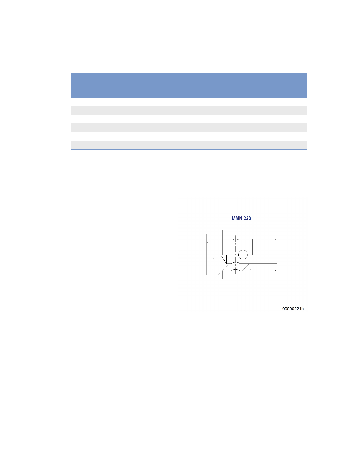
Tightening torques for banjo screws to MTN 5183-2 standard
This standard applies to banjo screws to MMN 223 and N 15011 sealed with sealing ring to DIN 7603Cu.
20 | General Information | MS150063/02E 2014-03
TIM-ID: 0000002333 - 015
Page 21
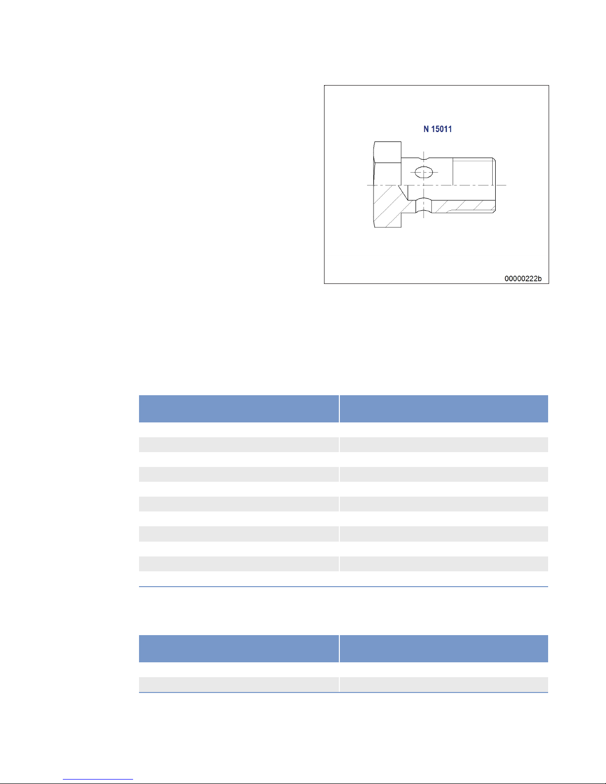
The stated tightening torques MA apply to steel (St) banjo screws with a phosphatized surface coating
and oiled, or galvanized, and to banjo screws made of copper/aluminum alloys.
Threads and mating faces beneath heads must be coated with engine oil prior to assembly.
An assembly tolerance of +10% of the figures in the table is permitted due to unavoidable deviations
during the tightening process.
Tightening torques for steel banjo screws
Thread
Screwed into steel/gray cast iron/Al alloy M
A
(Nm)
M8 x 1 10
M10 x 1 15
M12 x 1.5 20
M14 x 1.5 25
M16 x 1.5 25
M18 x 1.5 30
M22 x 1.5 60
M26 x 1.5 90
M30 x 1.5 130
M38 x 1.5 140
M45 x 1.5 160
MA= tightening torques
Tightening torques for banjo screws made of copper-aluminum alloy
Thread
Screwed into steel/gray cast iron/Al alloy M
A
(Nm)
M10 x 1 15
M16 x 1.5 30
MA= tightening torques
MS150063/02E 2014-03
| General Information | 21
TIM-ID: 0000002333 - 015
Page 22
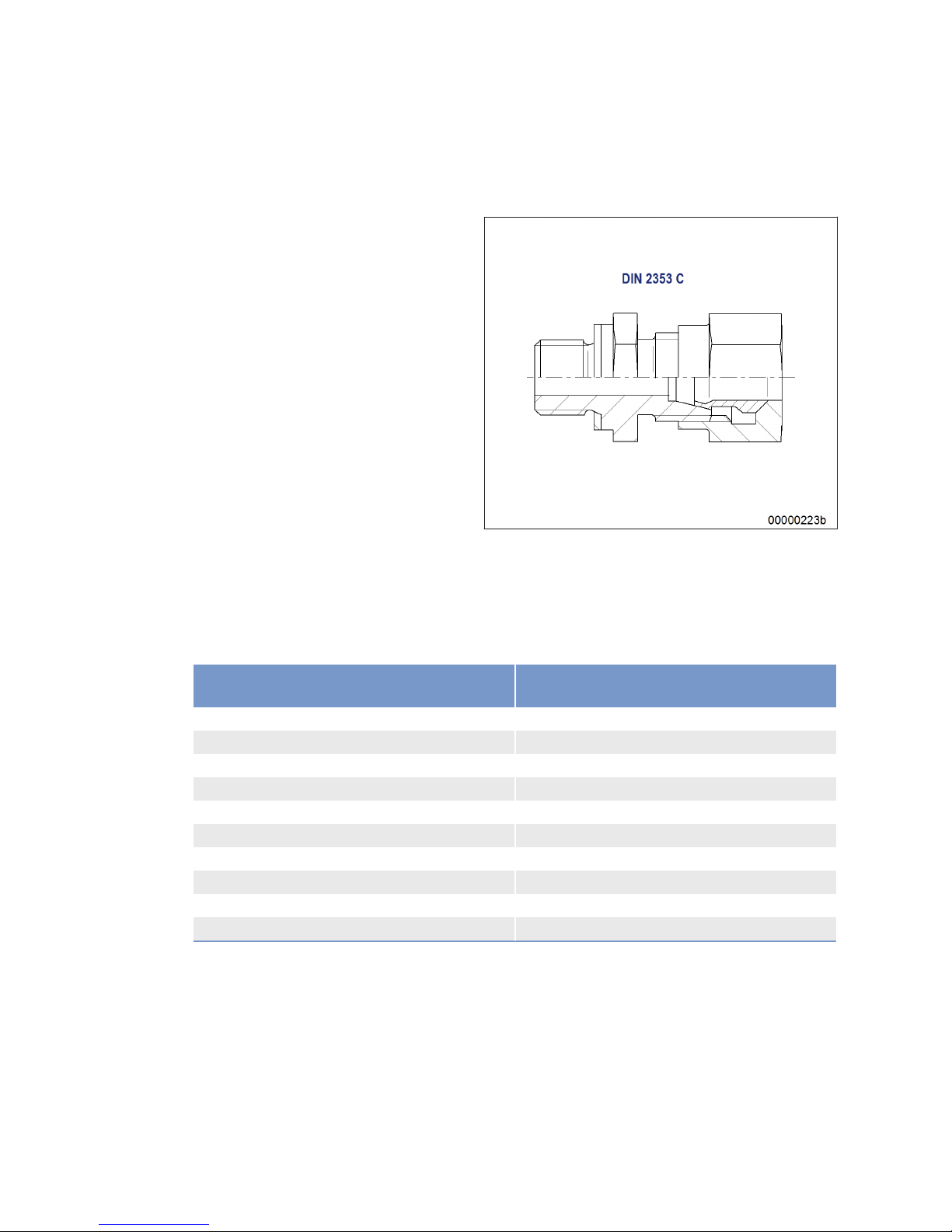
Tightening torques for male unions to MTN 5183-3 standard
This standard applies to male unions to DIN 2353 Series L with threaded end to DIN 3852 Form A
(sealed by sealing ring to DIN 7603-Cu).
Tightening torques MA are given for male unions made of steel (St) with phosphatized surface coating
and oiled, or galvanized.
Threads and mating faces beneath heads must be coated with engine oil prior to assembly.
An assembly tolerance of +10% of the figures in the table is permitted due to unavoidable deviations
during the tightening process.
Thread
Screwed into steel/gray cast iron M
A
(Nm)
M10 x 1 15
M12 x 1.5 20
M14 x 1.5 35
M16 x 1.5 50
M18 x 1.5 60
M22 x 1.5 70
M26 x 1.5 100
M32 x 2 160
M42 x 2 260
M48 x 2 320
MA= tightening torques
22 | General Information |
MS150063/02E 2014-03
TIM-ID: 0000002333 - 015
Page 23
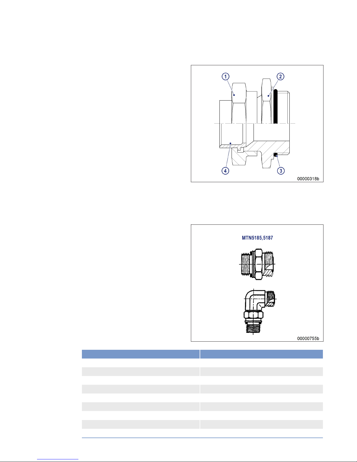
Tightening torques for union nuts to DIN 3859-2
1 Union nut
2 Union body
3 O-ring
4 Ferrule
Union nut: On installing the ball-type union, after tightening the union nut firmly by hand (noticeable
increase in force), it should be tightened another 1/4 turn (90°) past this point.
Tightening torques for spigot unions with O-ring to ISO 6149-2
Thread Torque (Nm) +10%
M8 x 1 10
M10 x 1 20
M12 x 1.5 35
M14 x 1.5 45
M16 x 1.5 55
M18 x 1.5 70
M20 x 1.5
1)
80
M22 x 1.5 100
M27 x 2 170
MS150063/02E 2014-03 | General Information | 23
TIM-ID: 0000002333 - 015
Page 24
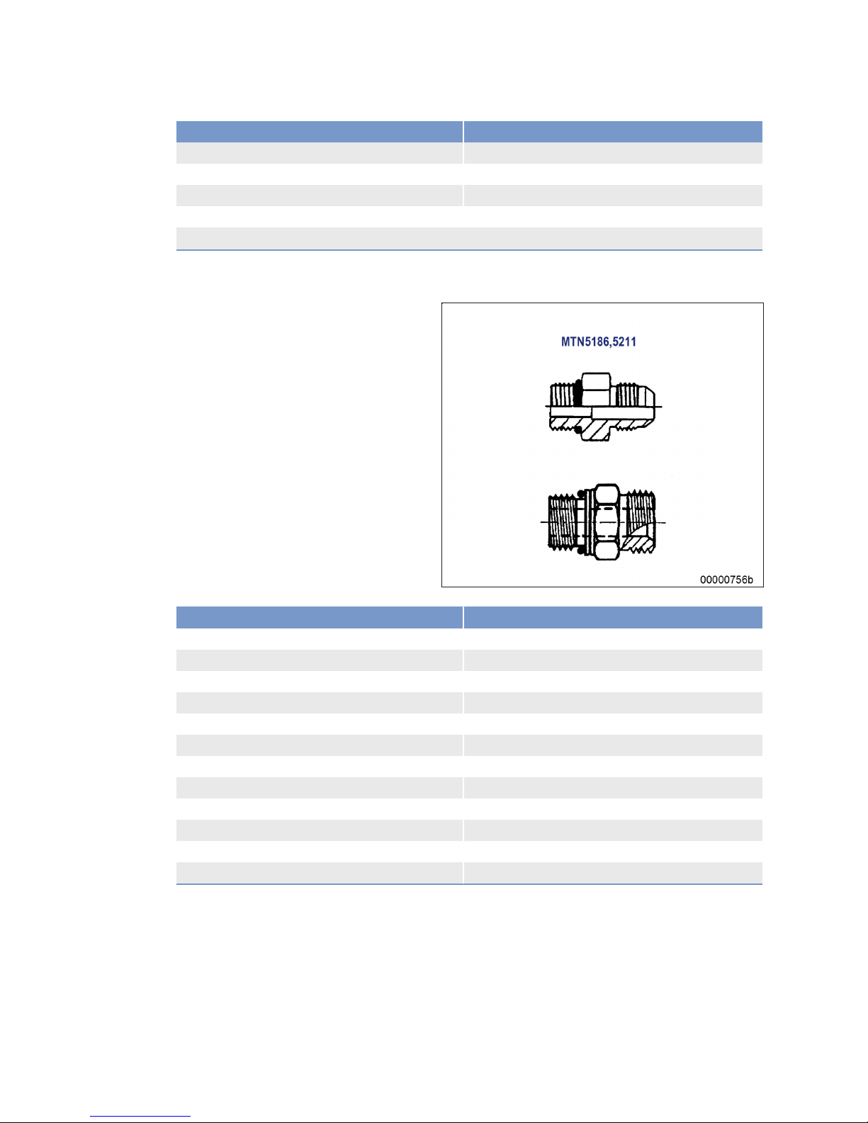
Thread Torque (Nm) +10%
M33 x 2 310
M42 x 2 330
M48 x 2 420
M60 x 2 500
1)
Only for sealing off installation spaces for screw-in valves (see ISO 7789)
Tightening torques for spigot unions with O-ring to ISO 6149-3
Thread Torque (Nm) +10%
M8 x 1 8
M10 x 1 15
M12 x 1.5 25
M14 x 1.5 35
M16 x 1.5 40
M18 x 1.5 45
M22 x 1.5 60
M27 x 2 100
M33 x 2 160
M42 x 2 210
M48 x 2 260
M60 x 2 315
24 | General Information | MS150063/02E 2014-03
TIM-ID: 0000002333 - 015
Page 25
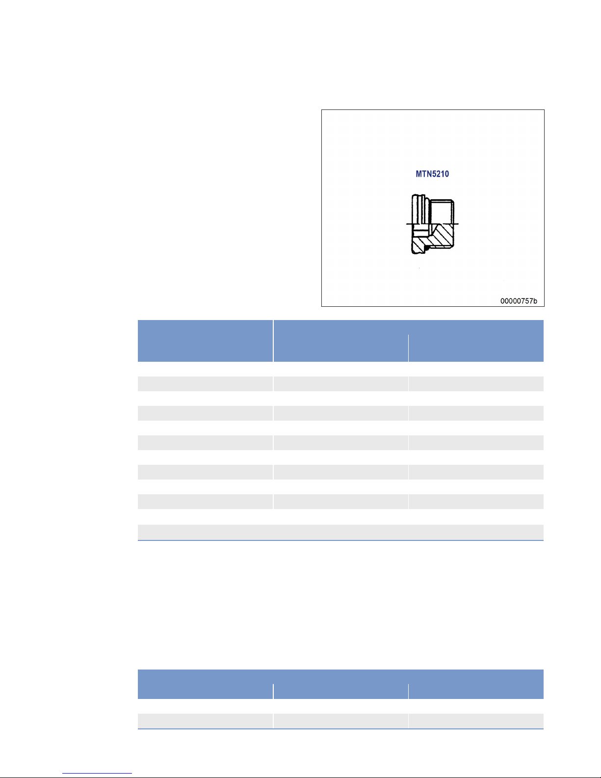
Tightening torques for plug screws to MTN 5183-6
Thread
Screwed into
Steel/gray cast iron M
A
(Nm)
AI alloy M
A
(Nm)
M10 x 1 20 10+ 2
M12 x 1.5 35 14+ 2
M14 x 1.5 45 15+ 3
M16 x 1.5 55 18+ 3
M18 x 1.5 70 23+ 3
M22 x 1.5 100 33+ 4
M27 x 2 170 57+ 5
M33 x 2 310 103+ 10
M42 x 2 330 110+ 11
M48 x 2 420 140+ 14
M60 x 2
1)
200+ 20
1)
Figure not yet determined
Assembly instructions and tightening torques for hose fittings with union nuts
These instructions do not apply to ORFS fittings. In contrast to the instructions for pipe unions, hose
fittings with sealing heads and the matching adapters must be fitted and connected as follows.
Hose fitting forming metallic seal with union nut: tighten union nut by hand then tighten a further
max. 1/4 of a turn with a wrench.
Hose fitting with O-ring and union nut: tighten union nut by hand then tighten a further max. 1/2 of a
turn with a wrench.
Hoses must be properly aligned before tightening the union nuts.
Sealing head/sealing cone with metric union nut
Metric thread Pipe outer dia. Torque (Nm)
M12 x 1.5 6 20
M14 x 1.5 8 38
MS150063/02E 2014-03 | General Information | 25
TIM-ID: 0000002333 - 015
Page 26

Sealing head/sealing cone with metric union nut
Metric thread Pipe outer dia. Torque (Nm)
M16 x 1.5 8
10
45
M18 x 1.5 10
12
51
M20 x 1.5 12 58
M22 x 1.5 14
15
74
M24 x 1.5 16 74
M26 x 1.5 18 105
M30 x 2 20
22
135
M36 x 2 25
28
166
M42 x 2 30 240
M45 x 2 35 290
M52 x 2 38
42
330
Sealing head with BSP union nut
BSPP thread Torque (Nm)
G1/4 20
G3/8 34
G1/2 60
G5/8 69
G3/4 115
G1 140
G1.1/4 210
G1.1/2 290
G2 400
26 | General Information | MS150063/02E 2014-03
TIM-ID: 0000002333 - 015
Page 27

2.2 Engine side and cylinder designations
Engine sides are always designated as viewed from the driving end (KS) (4).
For designation of the cylinders (to DIN ISO 1204) the letter "A" (1) is used to refer to the cylinders on
the left-hand side of the engine and the letter "B" (3) to refer to the cylinders on the right-hand side. The
cylinders of each bank are numbered consecutively, starting with No. 1 at the driving end.
The numbering of other engine components also starts with no. 1 at the driving end.
1 Left-hand side of engine
2 Free end
3 Right-hand side of engine
4 Driving end
MS150063/02E 2014-03 | General Information | 27
TIM-ID: 0000002185 - 012
Page 28

2.3 Product description
Description of the engine
Engine
The engine is a liquid-cooled four-stroke diesel engine with c.c.w. direction of rotation, direct injection,
sequential turbocharging and charge-air cooling.
An electronic management system provides engine control and monitoring.
Fuel system with Common Rail injection
Controlled by the electronic engine management system, the common rail injection system determines
injection pressure, injection timing and injection quantity independently of the engine speed.
Injection pressures up to 1800 bar ensure optimum fuel injection and combustion conditions.
Turbocharging system
The charging system comprises charge-air system, exhaust system and sequential turbocharging.
The exhaust system is equipped with triple-walled, water-cooled exhaust lines.
The triple-walled design permits
• low surface temperature,
• reduced thermal load,
• absolute gas-tightness.
Lube oil system
Wet-sump forced-feed lubrication system
Components supplied with oil:
• Bearings
• Piston cooling
• Control and actuating elements of the sequential turbocharging system
Cooling system
• Two separate cooling circuits:
– Engine coolant
– Raw water
• Coolant cooling by raw water-cooled plate-core heat exchanger
• Thermostat-controlled coolant system
• Coolant-cooled / preheated charge-air
• Coolant-cooled fuel return
Electronic system
Electronic control and monitoring system with integrated safety and test system with interfaces to the
Remote Control System (RCS) and to the Monitoring and Control System (MCS).
Connection box EIM (Engine Interface Module)
The Engine Interface Module (EIM) is the central connection box on the engine. It covers the entire minimum scope of a Series marine engine. It has no controls or parts requiring maintenance.
28 | General Information |
MS150063/02E 2014-03
TIM-ID: 0000002177 - 004
Page 29

Functions:
• Starter control (start repetition, tooth alignment, starter protection)
• Generator monitoring
• Open bus interface to the plant (SAE J1939)
• Emergency stop function with line break monitoring
• Redundant power supply
• Optional control of emergency air-shutoff flaps
• Key switch logic
• Interface to ECU and EMU
• MCS5 dialog interface
• Control of an MTU lube-oil priming pump (power components in separate MTU PPC Box)
• Connection facility for an MTU Local Operating Station (LOS)
Serial RS422 interface for diagnosis
The engine interface is divided into two parts. The first part is integrated in the engine wiring harness
via the 62-pole Tyco connector X52. The second part is formed by those signals involving a higher current. Such signals are routed out via M threaded pins and are also integrated in the engine wiring harness.
Functions
• ECU supply
• EMU supply
• Plant signals (ECU7 connector X1)
• Bus interface (2x MCS5 CAN)
• CAN dialog output (1x MCS5 CAN)
• ECU and EMU emergency stop
• Electric starter
• Terminal 45 starter A/B (engaged)
• Pneumatic starter
• Starting air pressure valve
• Starting air pressure sensor
• Barring gear (Barring Gear 1 and 2)
• Generator (with exciter control)
• Optional emergency air-shutoff flaps
• Activation of SDAF 1+2
• Feedback from SDAF 1+2
Electronic engine control unit (ECU)
Closed-loop control:
• Engine speed
• Fuel HP
Open-loop control:
• Injection (fuel pressure, injection timing, injection duration, operating status)
• Sequential turbocharging (cutting-in and out) with secondary turbocharger
• Engine protection with multi-stage safety systems:
– Power reduction
– Power limitation
– Emergency stop
MS150063/02E 2014-03
| General Information | 29
TIM-ID: 0000002177 - 004
Page 30
Monitoring:
• Exhaust gas temperature, A side
• Exhaust temperature, B-side
• Engine speed
• Oil pressure
• Differential oil pressure
• Coolant temperature
• Coolant level
• Exhaust turbocharger speed
• Leak fuel level
• Oil temperature
• Coolant pressure
• Fuel pressure after filter
Monitoring in engine room
Engine control and monitoring unit (LOP)
Functions:
• Engine speed, oil pressure and coolant temperature are monitored and displayed
• Integrated safety system
• Integrated Test System
• Redundant CAN bus interface to governor and higher-level control and monitoring system
• 24 V DC supply
SOLAS – Fire protection specifications
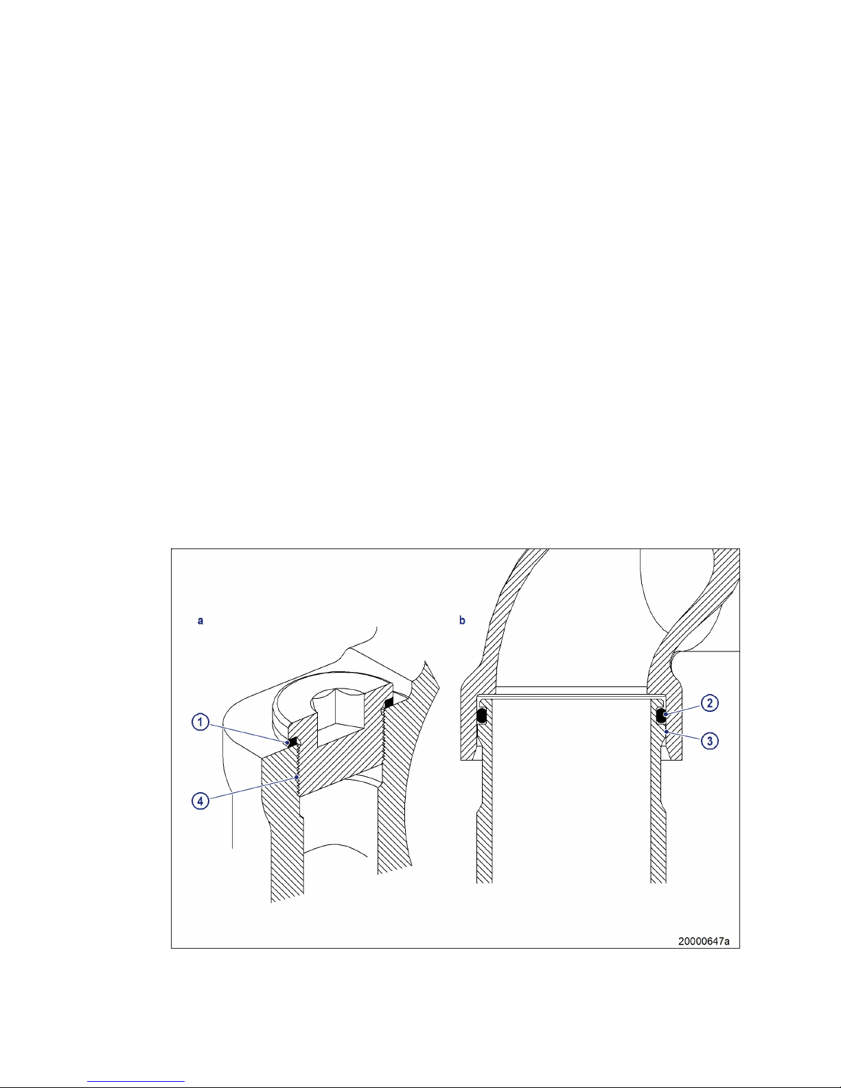
Special connections
In case of leakage, the connection types shown above are spray-protected even without a cover and
have been confirmed compliant with SOLAS by GL and DNV.
30 | General Information |
MS150063/02E 2014-03
TIM-ID: 0000002177 - 004
Page 31
Plug-in pipe union
The sleeve (3) covers the joint to prevent lateral spray.
Only leak-off along the line is possible, the pressure decreases significantly if an O-ring (2) fault occurs.
The connection is confirmed as compliant with SOLAS by DNV and GL.
Plugs and sensors
Screw-in plugs (4) are sealed toward the outside either with a copper sealing ring (1), according to DIN,
or an O-ring (ISO).
In case of a loose thread or a faulty sealing ring (1), the liquid first has to pass the thread.
The pressure is so greatly reduced by this and the faulty sealing ring (1) that any leakage is not under
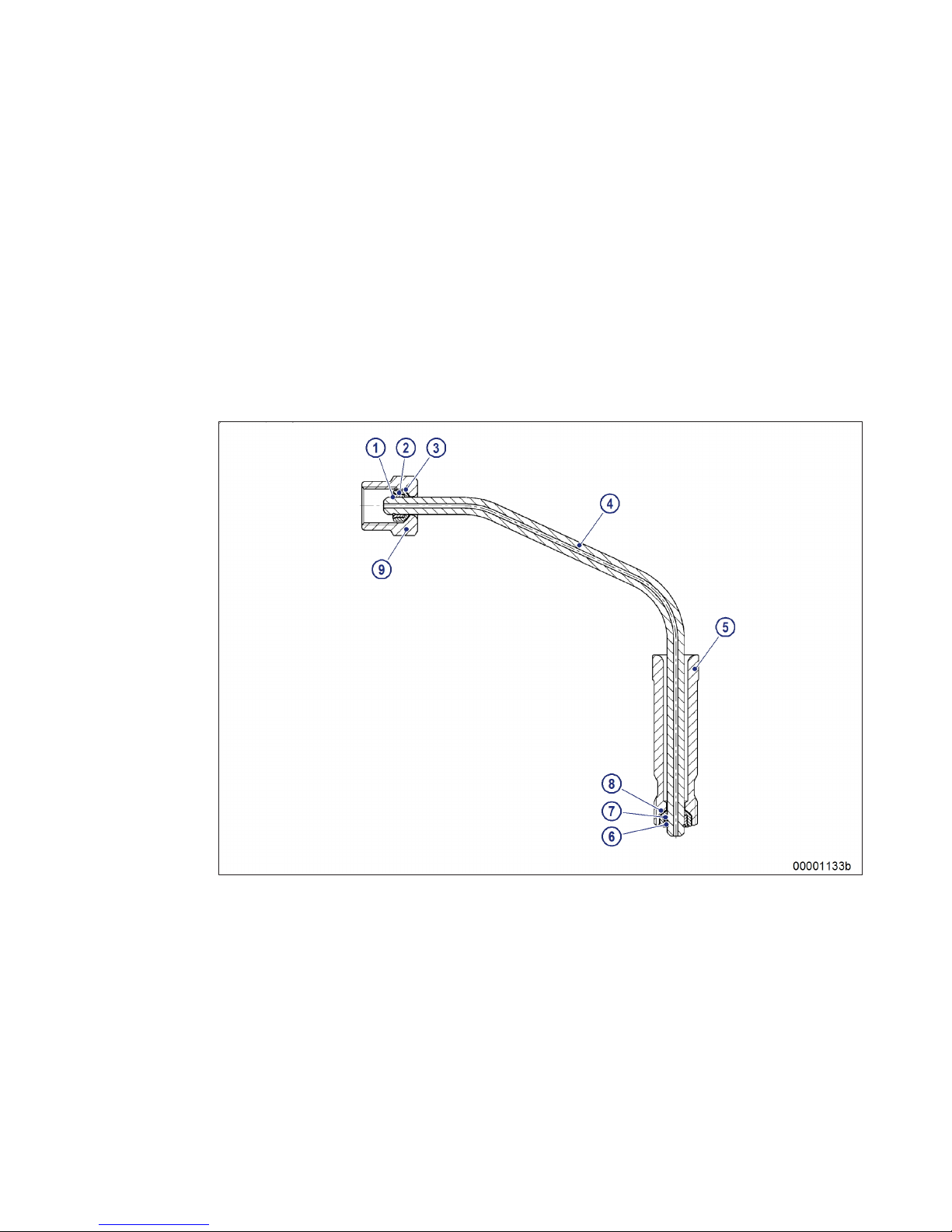
pressure.
HP line between fuel injector and HP accumulator
1 Support ring
2 V-ring
3 Thrust ring
4 HP line
5 Thrust screw
6 Support ring
7 Thrust ring
8 V-ring
9 Union nut
MS150063/02E 2014-03 | General Information | 31
TIM-ID: 0000002177 - 004
Page 32
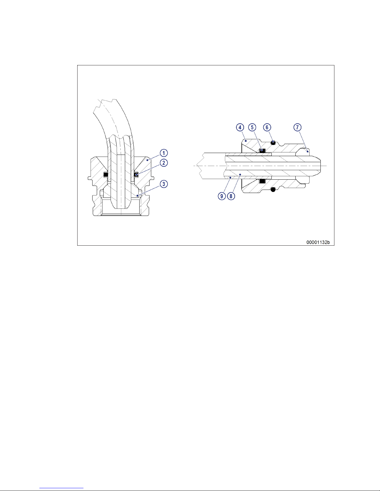
HP line between distributor and HP accumulator
1 Union nut
2 O-ring
3 Thrust ring
4 Thrust screw
5 O-ring
6 O-ring
7 Thrust ring
8 Pressure pipe
9 Jacket pipe
32 | General Information | MS150063/02E 2014-03
TIM-ID: 0000002177 - 004
Page 33
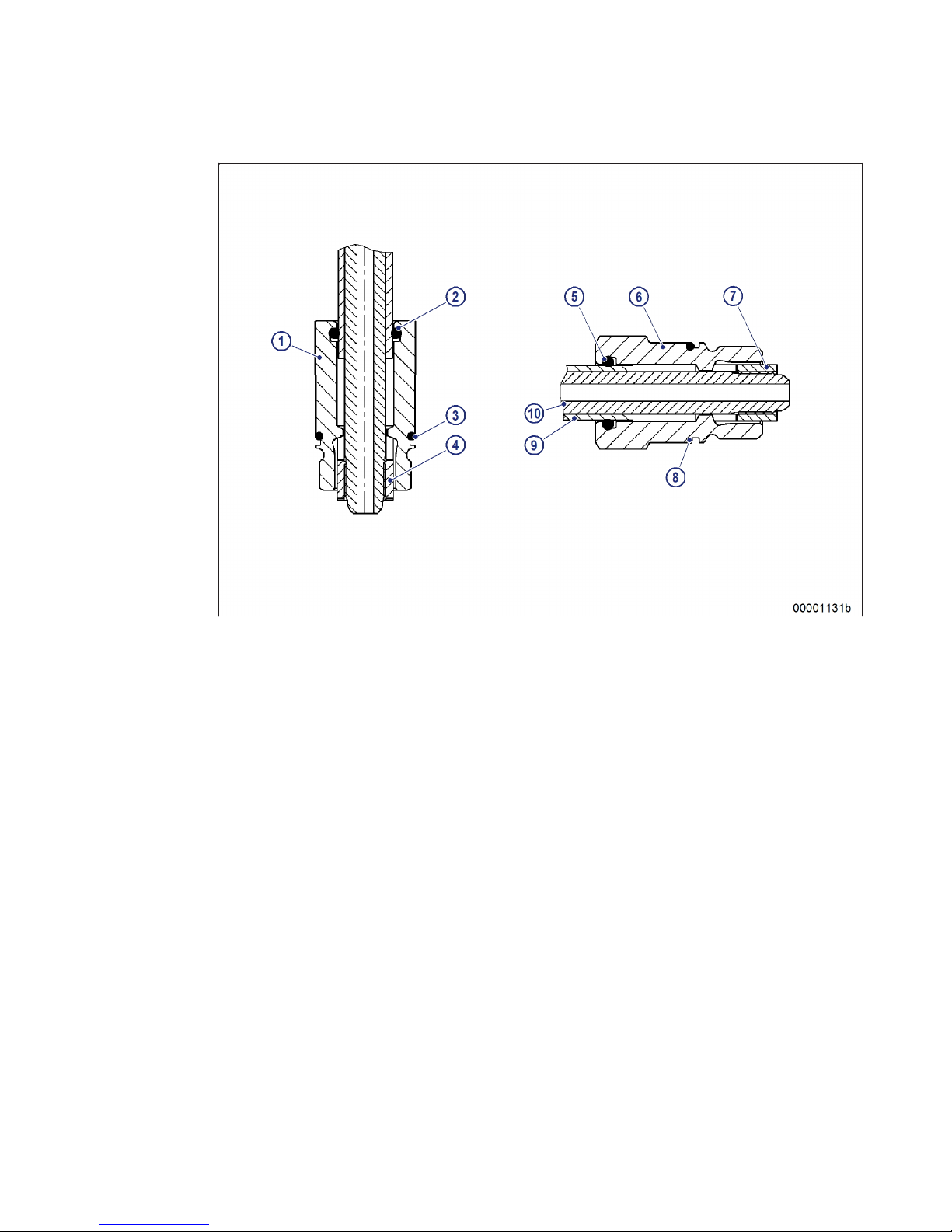
HP line between distributor and HP accumulator
1 Jacket pipe
2 O-ring
3 O-ring
4 Thrust ring
5 O-ring
6 Thrust screw
7 Thrust ring
8 O-ring
9 HP line
10 Pressure pipe
Leak-off fuel caused by leakages from the sealing cones or the HP lines is returned to the HP pump,
from where it is routed at atmospheric pressure into a level-monitored leak-fuel tank.
MS150063/02E 2014-03 | General Information | 33
TIM-ID: 0000002177 - 004
Page 34
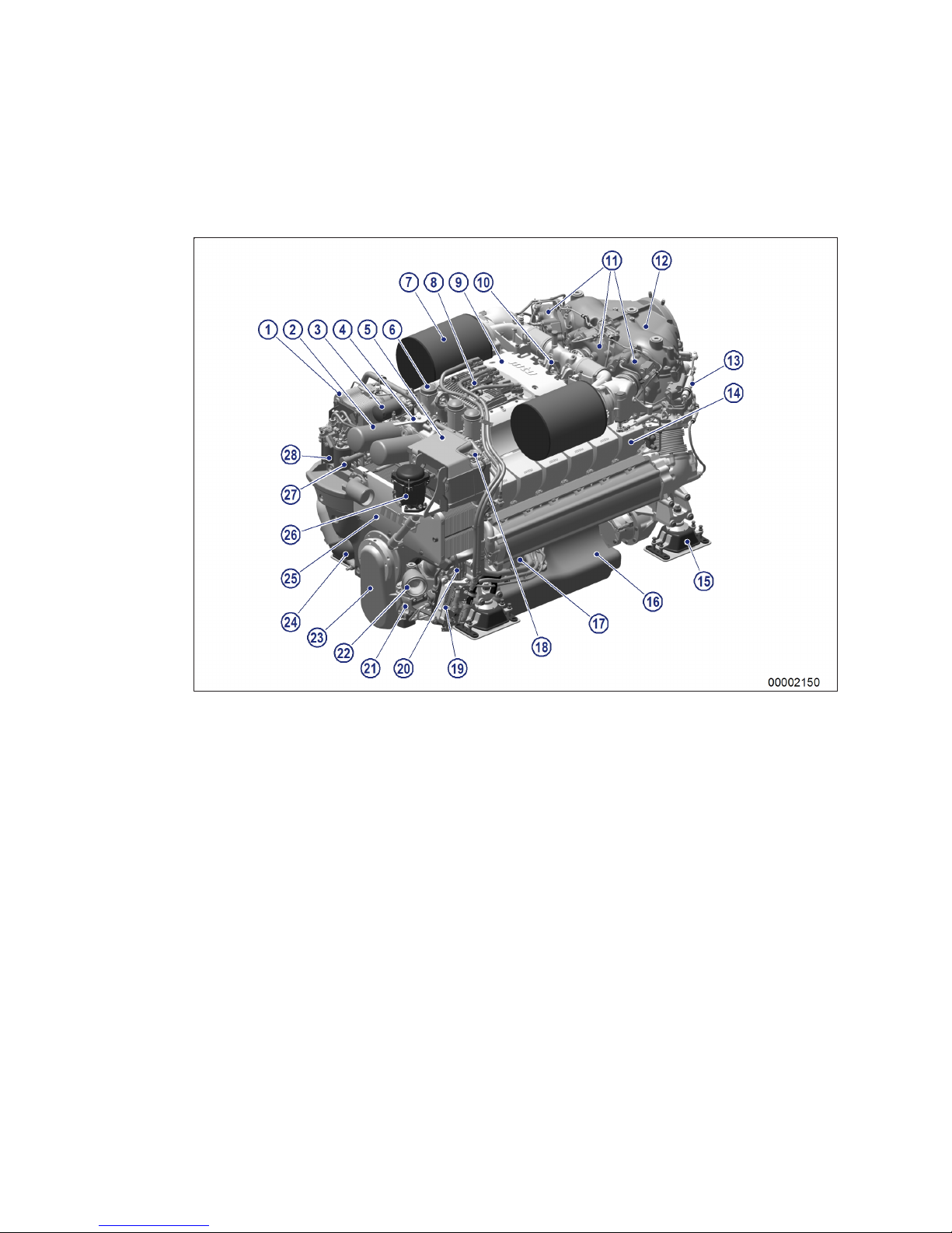
2.4 Engine layout
View on free end
Also valid for 16V engines
1 Engine oil heat exchanger
2 Engine oil filter
3 Coolant filter
4 Diverter lever for engine
oil filter
5 Coolant distribution hous-
ing with integrated expansion tank
6 Oil separator
7 Air filter (air intake)
8 Engine governor
9 Air collecting housing
10 Engine lifting eyes
11 Exhaust turbocharger
12 Actuating cylinder for ex-
haust flap
13 Carrier housing
14 Cylinder head cover
15 Engine mounting
16 Oil pan
17 Battery-charging generator
18 Coolant filler neck
19 Engine Interface Module
EIM
20 Raw water connection to
gearbox cooling system
21 Raw water pump
22 Raw water connection
from sea
23 Protective cover (belt pul-
ley)
24 Coolant pump
25 Plate-core heat exchanger
26 Centrifugal oil filter
27 Fuel priming pump
28 Fuel filter
KGS = engine free end
34 | General Information | MS150063/02E 2014-03
TIM-ID: 0000009987 - 005
Page 35
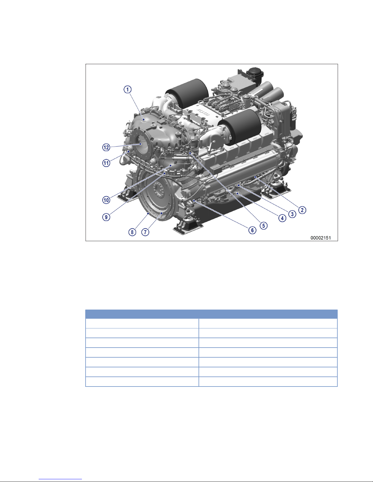
View on driving end
1 Carrier housing upper sec-
tion
2 HP fuel pump
3 Oil filler neck
4 Oil dipstick
5 4/2-way directional con-
trol valve
6 Electric starter
7 Drive flange
8 Flywheel housing
9 Carrier housing lower sec-
tion
10 Carrier housing middle
section
11 Relief valve
12 Exhaust outlet
KS = engine driving end
Engine model designation
Key to the engine model designation 12V/16V 2000 Mxyz
12/16 Number of cylinders
V Cylinder arrangement: V engine
2000 Series
M Application
x Application segment (4, 5, 6, 7, 9)
y Design index (0,1, 2,...)
z Special features
MS150063/02E 2014-03 | General Information | 35
TIM-ID: 0000009987 - 005
Page 36

2.5 Sensors and actuators – Overview
Engine plan view
Deviations from illustrations are insignificant.
Also applies similarly to 12V.
Item Designation Monitoring of
1 B3 Intake air temperature
2 B9 Charge-air temperature
3 B7 Lube oil temperature
4 B10 Charge-air pressure
5 B44 Turbocharger speed
36 | General Information | MS150063/02E 2014-03
TIM-ID: 0000008412 - 005
Page 37
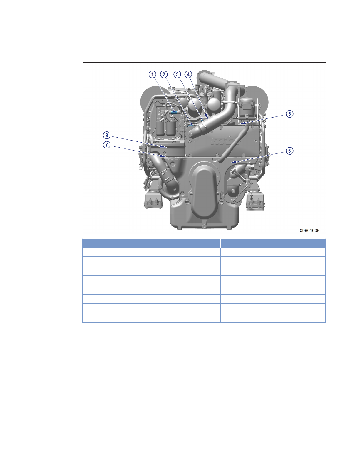
Engine free end
Item Designation Monitoring of
1 B34 Fuel pressure after filter
2 B5.3 (optional) Lube oil pressure before filter
3 B5.1 Lube oil pressure after filter
4 B5.2 (optional) Lube oil pressure after filter
5 F33 Engine coolant level, expansion tank
6 B21 (optional) Raw water pressure
7 B6.2 (optional) Coolant temperature
8 B6.1 Coolant temperature
MS150063/02E 2014-03 | General Information | 37
TIM-ID: 0000008412 - 005
Page 38
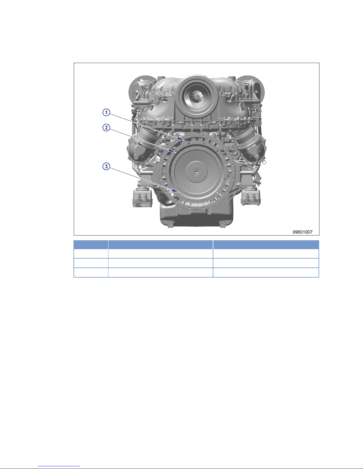
Engine driving end
Item Designation Monitoring of
1 B1 (ECU) Camshaft speed
2 B13.2 (optional EMU) Crankshaft speed
3 B13 (ECU) Crankshaft speed
38 | General Information | MS150063/02E 2014-03
TIM-ID: 0000008412 - 005
Page 39

Engine, right side
Item Designation Monitoring of
1 F41 2-2-directional control valve
2 YB33 Fuel temperature
3 B48 Fuel pressure (in rail)
4 B16 (optional) Coolant pressure
5 F46 Leak fuel level
6 Y27.2 4-2-directional control valve, B-side
7 B4.22 Exhaust temperature, B-side
MS150063/02E 2014-03 | General Information | 39
TIM-ID: 0000008412 - 005
Page 40

Engine, left side
Item Designation Monitoring of
1 B4.21 Exhaust gas temperature, A-side
2 Y27.1 4-2-directional control valve, A-side
3 B54 (optional) Lube oil pressure, replenishment pump
System sensors
These sensors are fitted outside the engine.
Designation Monitoring of
B19 Starting-air pressure
B70 Fuel prefilter water level
B41 Exhaust back pressure
S37 Start interlock, switching status
40 | General Information | MS150063/02E 2014-03
TIM-ID: 0000008412 - 005
Page 41
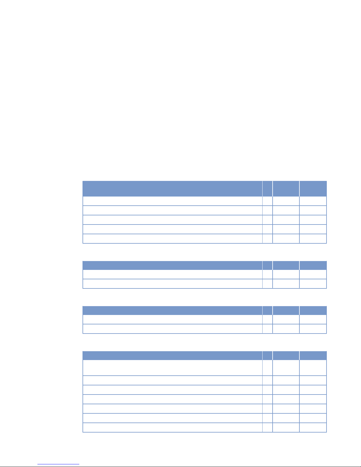
3 Technical Data
3.1 12V 2000 M84 engine data
Explanation:
DL Ref. value: Continuous power
BL Ref. value: Fuel stop power
A Design value
G Guaranteed value
R Guideline value
L Limit value, up to which the engine can be operated, without change (e.g. of power setting)
N Not yet defined value
- Not applicable
X Applicable
Reference conditions
Engine model 12V2000
M84
Application group 1D
Intake air temperature °C 25
Raw water inlet temperature °C 25
Barometric pressure mbar 1000
Site altitude above sea level m 100
Power-related data (power ratings are net brake power as per ISO 3046)
Number of cylinders 12
Rated engine speed A rpm 2450
Fuel stop power ISO 3046 A kW 1220
General conditions (for maximum power)
Number of cylinders 12
Intake depression (new filter) A mbar 15
Intake depression, max. L mbar 30
Model related data (basic design)
Number of cylinders 12
Cylinder arrangement: V angle Degrees
(°)
90
Bore mm 135
Stroke mm 156
Cylinder displacement Liters 2.23
Total displacement Liters 26.76
Number of inlet valves per cylinder 2
Number of exhaust valves per cylinder 2
MS150063/02E 2014-03 | Technical Data | 41
TIM-ID: 0000010851 - 002
Page 42
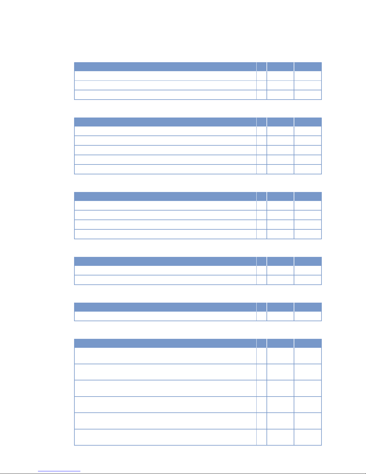
Raw water circuit (open circuit)
Number of cylinders 12
Raw water pump: Inlet pressure, min. L bar -0.4
Raw water pump: inlet pressure, max. L bar +0.5
Pressure loss in engine-external raw water system, max. L bar 0.7
Lube oil system
Number of cylinders 12
Lube oil operating temperature before engine, from R °C 82
Lube-oil operating temperature before engine, to R °C 90
Lube oil operating pressure before engine, from R bar 7.5
Lube oil operating pressure before engine, to R bar 8.5
Lube oil operating pressure (low idle) (meas. point: before engine) R bar 3
Fuel system
Number of cylinders 12
Fuel pressure at engine inlet connection, min. (when engine is starting) L bar -0.3
Fuel pressure at engine inlet connection, min. (during engine operation) L bar -0.3
Fuel pressure at engine inlet connection, max. (when engine is starting) L bar +0.25
Fuel supply flow, max. R liters/min 6.3
General operating data
Number of cylinders 12
Firing speed, from R rpm 100
Firing speed, to R rpm 120
Starter (electric)
Number of cylinders 12
Rated starter voltage (standard design) R V= 24
Inclinations - standard oil system (reference: waterline)
Number of cylinders 12
Longitudinal inclination, continuous max. driving end down (Option: max. operating inclinations)
L Degrees
(°)
15
Longitudinal inclination, temporary max. driving end down (Option: max. operating inclinations)
L Degrees
(°)
22.5
Longitudinal inclination, continuous max. driving end up (Option: max. operating inclinations)
L Degrees
(°)
0
Longitudinal inclination, temporary max., driving end up (Option: max. operating inclinations)
L Degrees
(°)
10
Transverse inclination, continuous max. (Option: max. operating inclinations) L Degrees
(°)
22.5
Transverse inclination, temporary max. (Option: max. operating inclinations) L Degrees
(°)
32.5
42 | Technical Data | MS150063/02E 2014-03
TIM-ID: 0000010851 - 002
Page 43

Capacities
Number of cylinders 12
Engine coolant, engine side (with cooling system) R Liters 125
Engine oil capacity, initial filling (standard oil system) (Option: max. operating
inclinations)
R Liters 123
Oil change quantity, max. (standard oil system) (Option: max. operating inclinations)
R Liters 113
Oil pan capacity at dipstick mark “min.” (standard oil system) (Option: max.
operating inclinations)
L Liters 87
Oil pan capacity at dipstick mark “max.” (standard oil system) (Option: max.
operating inclinations)
L Liters 105
Weights / main dimensions
Number of cylinders 12
Engine dry weight (with attached standard accessories, without coupling) R kg 2780
Acoustics
Number of cylinders 12
Exhaust noise, unsilenced - BL (free-field sound pressure level Lp, 1m distance, ISO 6798, +3dB(A) tolerance)
R dB(A) 108
Engine surface noise with attenuated intake noise (filter) - BL (free-field sound
power level Lp, 1 m distance, ISO 6798, +2dB(A) tolerance)
R dB(A) 103
MS150063/02E 2014-03 | Technical Data | 43
TIM-ID: 0000010851 - 002
Page 44

3.2 16V 2000 M84 engine data
Explanation:
DL Ref. value: Continuous power
BL Ref. value: Fuel stop power
A Design value
G Guaranteed value
R Guideline value
L Limit value, up to which the engine can be operated, without change (e.g. of power setting)
N Not yet defined value
- Not applicable
X Applicable
Reference conditions
Engine model 16V2000
M84
Application group 1D
Intake air temperature °C 25
Raw water inlet temperature °C 25
Barometric pressure mbar 1000
Site altitude above sea level m 100
Power-related data (power ratings are net brake power as per ISO 3046)
Number of cylinders 16
Rated engine speed A rpm 2450
Fuel stop power ISO 3046 A kW 1630
General conditions (for maximum power)
Number of cylinders 16
Intake depression (new filter) A mbar 15
Intake depression, max. L mbar 30
Model related data (basic design)
Number of cylinders 16
Cylinder arrangement: V angle Degrees
(°)
90
Bore mm 135
Stroke mm 156
Cylinder displacement Liters 2.23
Total displacement Liters 35.68
Number of inlet valves per cylinder 2
Number of exhaust valves per cylinder 2
44 | Technical Data | MS150063/02E 2014-03
TIM-ID: 0000010886 - 002
Page 45

Raw water circuit (open circuit)
Number of cylinders 16
Raw water pump: Inlet pressure, min. L bar -0.4
Raw water pump: inlet pressure, max. L bar +0.5
Pressure loss in engine-external raw water system, max. L bar 0.7
Lube oil system
Number of cylinders 16
Lube oil operating temperature before engine, from R °C 75
Lube-oil operating temperature before engine, to R °C 94
Lube oil operating pressure before engine, from R bar 6.0
Lube oil operating pressure before engine, to R bar 7.5
Lube oil operating pressure (low idle) (meas. point: before engine) R bar 2.5
Fuel system
Number of cylinders 16
Fuel pressure at engine inlet connection, min. (when engine is starting) L bar -0.3
Fuel pressure at engine inlet connection, min. (during engine operation) L bar -0.3
Fuel pressure at engine inlet connection, max. (when engine is starting) L bar +0.25
Fuel supply flow, max. R liters/min 7.3
General operating data
Number of cylinders 16
Firing speed, from R rpm 100
Firing speed, to R rpm 120
Starter (electric)
Number of cylinders 16
Rated starter voltage (standard design) R V= 24
Inclinations - standard oil system (reference: waterline)
Number of cylinders 16
Longitudinal inclination, continuous max. driving end down (Option: max. operating inclinations)
L Degrees
(°)
15
Longitudinal inclination, temporary max. driving end down (Option: max. operating inclinations)
L Degrees
(°)
22.5
Longitudinal inclination, continuous max. driving end up (Option: max. operating inclinations)
L Degrees
(°)
0
Longitudinal inclination, temporary max., driving end up (Option: max. operating inclinations)
L Degrees
(°)
10
Transverse inclination, continuous max. (Option: max. operating inclinations) L Degrees
(°)
22.5
Transverse inclination, temporary max. (Option: max. operating inclinations) L Degrees
(°)
32.5
MS150063/02E 2014-03 | Technical Data | 45
TIM-ID: 0000010886 - 002
Page 46

Capacities
Number of cylinders 16
Engine coolant, engine side (with cooling system) R Liters 135
Engine oil capacity, initial filling (standard oil system) (Option: max. operating
inclinations)
R Liters 168
Oil change quantity, max. (standard oil system) (Option: max. operating inclinations)
R Liters 155
Oil pan capacity at dipstick mark “min.” (standard oil system) (Option: max.
operating inclinations)
L Liters 115
Oil pan capacity at dipstick mark “max.” (standard oil system) (Option: max.
operating inclinations)
L Liters 138
Weights / main dimensions
Number of cylinders 16
Engine dry weight (with attached standard accessories, without coupling) R kg 3337
Acoustics
Number of cylinders 16
Exhaust noise, unsilenced - BL (free-field sound pressure level Lp, 1m distance, ISO 6798, +3dB(A) tolerance)
R dB(A) 109
Engine surface noise with attenuated intake noise (filter) - BL (free-field sound
power level Lp, 1 m distance, ISO 6798, +2dB(A) tolerance)
R dB(A) 106
46 | Technical Data | MS150063/02E 2014-03
TIM-ID: 0000010886 - 002
Page 47

3.3 Firing order
Firing order
12 V A1-B5-A5-B3-A3-B6-A6-B2-A2-B4-A4-B1
16 V A1-B5-A3-A5-B2-B8-A2-A8-B3-A7-B4-B6-A4-A6-B1-B7
MS150063/02E 2014-03 | Technical Data | 47
TIM-ID: 0000038135 - 001
Page 48
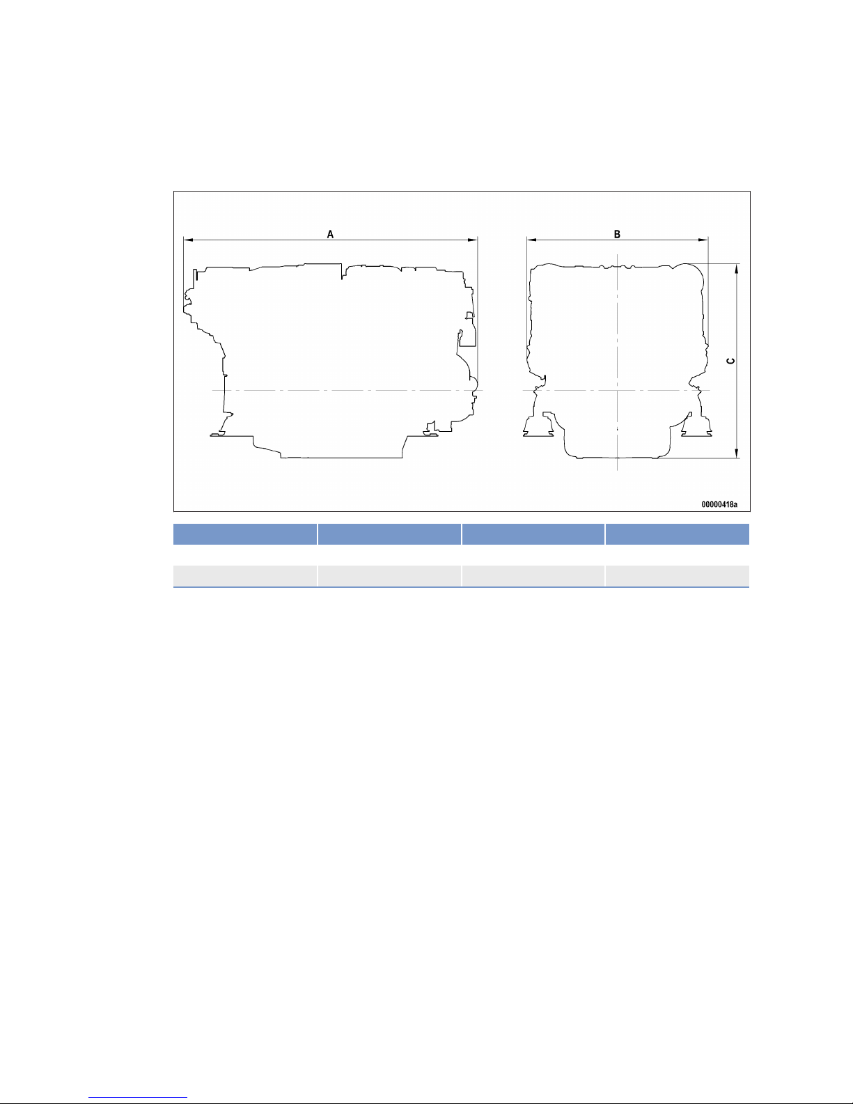
3.4 Engine – Main dimensions
Main dimensions
Engine model Length (A) Width (B) Height (C)
12V 2000 M84 approx. 2094 mm approx. 1295 mm approx. 1350 mm
16V 2000 M84 approx. 2511 mm approx. 1295 mm approx. 1390 mm
48 | Technical Data | MS150063/02E 2014-03
TIM-ID: 0000050223 - 001
Page 49

4 Operation
4.1 Putting the engine into operation after extended out-of-service
periods (>3 months)
Preconditions
☑Engine is stopped and starting disabled.
☑MTU Preservation and Represervation Instructions (A001070/..) available.
Putting the engine into operation (out-of-service period > 3 months)
Item Action
Engine Depreserve (→ MTU Preservation and Represervation Instructions
A001070/..).
Lube oil system Check engine oil level (→ Page 105).
Fuel prefilter Fill with fuel (→ Page 98).
Fuel prefilter, pressure gage Align adjustable pointer with position of pressure indicator (→ Page 93).
Fuel system Vent (→ Page 90).
Raw water pump (if located
above waterline)
Prime (approx. 3 to 4 liters).
Filling point (→ Page 112).
Coolant circuit If engine is out of service for more than one year, change engine coolant
(→ Page 118).
Coolant circuit Check coolant level (→ Page 117).
Coolant circuit Heat engine coolant with coolant preheating unit.
Engine Control Unit ECU Check plug connections (→ Page 136).
Engine Interface Module EIM Check plug connections (→ Page 138).
Engine Monitoring Unit EMU Check plug connections (→ Page 137).
MS150063/02E 2014-03 | Operation | 49
TIM-ID: 0000002213 - 004
Page 50

4.2 Engine – Putting into operation after scheduled out-of-serviceperiod
Preconditions
☑Engine is stopped and starting disabled.
Putting into operation
Item Action
Lube oil system Check engine oil level (→ Page 105).
Coolant circuit Check coolant level (→ Page 117).
Coolant circuit Heat engine coolant with coolant preheating unit.
Fuel prefilter Drain water and contaminants (→ Page 94).
Battery-charging generator
drive
Check condition of drive belt (→ Page 125).
Engine Control Unit ECU Check plug connections (→ Page 136).
Engine Interface Module EIM Check plug connections (→ Page 138).
Engine Monitoring Unit EMU Check plug connections (→ Page 137).
50 | Operation | MS150063/02E 2014-03
TIM-ID: 0000002689 - 003
Page 51

4.3 Tasks after extended out-of-service periods (>3 weeks)
Tasks after extended out-of-service periods (>3 weeks)
Note: Operate fuel treatment system for at least 5 minutes.
1. Start up fuel treatment system (→ Page 53).
2. Shut down fuel treatment system (→ Page 61).
MS150063/02E 2014-03 | Operation | 51
TIM-ID: 0000007730 - 005
Page 52

4.4 Checks prior to start-up
Checks prior to start-up
1. Check tank and the entire pipework for cleanness. If microorganisms are detected:
a) Clean affected components.
b) Disinfect affected components with biocides (→ MTU Fluids and Lubricants Specifications
A001061/..).
2. Close drain valves on housing.
3. Open all supply and discharge valves.
4. Switch on fuel treatment system (→ Page 56).
5. Check direction of rotation of pump.
6. Vent bypass and fuel lines of the system.
a) Open ball valve for pressure tank.
b) Open ball valve for overflow tank.
c) Close ball valve at the inlet to the fuel treatment system.
Result: Bypass line is vented via the overflow tank.
d) Open ball valve at the inlet to the fuel treatment system.
7. Check the fuel treatment system for leaks.
Result: The fuel treatment system is ready for operation.
52 | Operation | MS150063/02E 2014-03
TIM-ID: 0000007736 - 005
Page 53
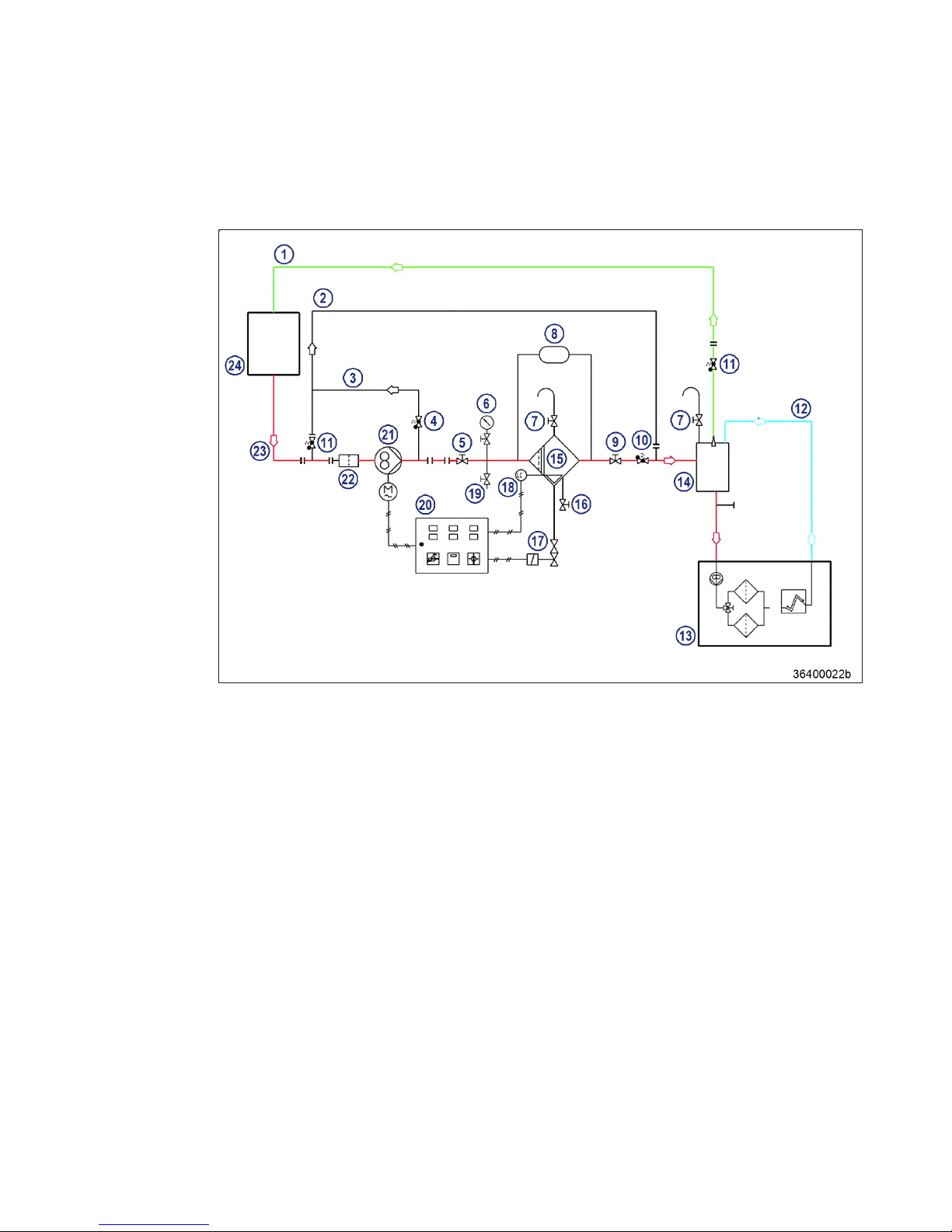
4.5 Fuel treatment system – Putting into operation
Fuel treatment system – Overview
1. Switch on fuel treatment system (→ Page 56).
2. Check the differential pressure at differential pressure gauge (8). Differential pressure in a new system:
0.1 bar to 0.3 bar.
Result: If no differential pressure is measured, the coalescer filter element is probably being bypassed.
1. Remove coalescer filter element (→ Page 131).
2. Check sealing faces on coalescer filter element and in the pressure tank.
Initial operation: HAT
1. Replace fuel filter on engine (→ Page 91).
Note: Determine the suction pressure upstream of the engine-mounted fuel delivery pump.
2. Install a pressure gauge in the fuel supply line from the shipyard-side fuel system to the engine.
3. Switch on fuel treatment system and operate it for some minutes (→ Page 56).
Result: Fuel is sucked from the tank, dirt particles and water are filtered and separated, then the fuel is deliv-
ered via the overflow tank back to the tank. Water which has settled in the tank is separated.
4. Start engine (→ Page 57).
5. Run engine at idling speed.
6. Check suction pressure (see technical data of the engine) at the engine-mounted fuel delivery pump.
Note: If the suction pressure is within the permissible limits and engine operation is satisfactory.
7. Increase engine speed to 1000 rpm and monitor suction pressure.
8. Check suction pressure at the engine-mounted fuel delivery pump.
Result: If the values are within the limits specified by the manufacturer, the system is ready to start filter re-
placement simulation with the engine running as part of the Harbor Acceptance Tests.
MS150063/02E 2014-03
| Operation | 53
TIM-ID: 0000007738 - 006
Page 54

Simulation of filter replacement with the engine running: HAT
1. Switch on fuel treatment system (→ Page 56).
2. Start engine (→ Page 57).
3. Run engine at idling speed.
4. Close ball cock (5) at the inlet to the fuel treatment system.
Result: The pressure upstream of the fuel treatment system increases until the overflow valve at the pump unit
opens and fuel flows through bypass (3) and bypass (2).
5. Open ball cock (19).
Result: Fuel emerges. If no fuel emerges:
• Open ball cock (5) at the inlet to the fuel treatment system.
• No function of bypasses (2) and (3); carry out functional test of bypasses (2) and (3) .
6. Check suction pressure (see technical data of the engine) at the fuel delivery pump.
Note: If the suction pressure is within the permissible limits and engine operation is satisfactory.
7. Increase engine speed to 1000 rpm and monitor suction pressure.
Result: If all engine operating values are within the specified limits, open ball cock (5) at the inlet to the fuel
treatment system.
Simulation of power failure (emergency): HAT
1. Switch on fuel treatment system (→ Page 56).
2. Start engine (→ Page 57).
3. Run engine at idling speed.
4. Switch off pump (21) on switch cabinet.
Result: The engine-mounted fuel delivery pump sucks fuel via bypass (2) directly from the tank.
5. Check suction pressure at the engine-mounted fuel delivery pump.
Note: If the suction pressure is within the permissible limits and engine operation is satisfactory.
6. Increase engine speed to 1000 rpm and monitor suction pressure.
Result: If the suction pressure is within the specified limits, simulation was successful.
Simulation of power failure (emergency): SAT
1. Switch on fuel treatment system (→ Page 56).
2. Start engine (→ Page 57).
3. Run engine at idling speed.
4. Switch off pump (21) on switch cabinet.
Result: The engine-mounted fuel delivery pump sucks fuel via bypass (2) directly from the tank.
5. Check suction pressure at the engine-mounted fuel delivery pump.
Note: If the suction pressure is within the permissible limits and engine operation is satisfactory.
6. Operate engine at full load and monitor suction pressure.
Result: If the suction pressure is within the specified limits, simulation was successful.
54 | Operation | MS150063/02E 2014-03
TIM-ID: 0000007738 - 006
Page 55
4.6 Operational checks
DANGER
Rotating and moving engine parts.
Risk of crushing, danger of parts of the body being caught or pulled in!
• Only run the engine at low power. Keep away from the engine's danger zone.
WARNING
High level of engine noise when the engine is running.
Risk of damage to hearing!
• Wear ear protectors.
Operational checks
Item Action
Engine under load
Engine at nominal speed
Visually inspect engine for leaks and general condition;
Check for abnormal running noises and vibration;
Check exhaust color (→ Page 65).
Fuel prefilter Check if suction-side pressure indicated at the fuel prefilter is within the limit
(→ Page 93).
Drain water and contaminants (→ Page 94).
Air filter Check signal ring position of contamination indicator (→ Page 103).
Replace air filter (→ Page 101), if the signal ring is completely visible in the
service indicator observation window.
HT coolant pump Check relief bore for oil and coolant discharge and contamination
(→ Page 121).
Raw water pump Check relief bore for oil and water discharge and contamination
(→ Page 124).
Intercooler Check condensate drain (if applicable) (→ Page 100).
Engine oil Check engine oil level (→ Page 105).
MS150063/02E 2014-03 | Operation | 55
TIM-ID: 0000002274 - 006
Page 56
4.7 Fuel treatment system – Switching on
Preconditions
☑The on-board power supply is switched on.
NOTICE
Risk of damage to engine/system.
Risk of severe damage to property!
• Before switching on, ensure that the engine/system is ready for operation.
• Before switching on, ensure that all housings are closed.
• Before switching on, ensure that no work is in progress anywhere on the entire system.
Fuel treatment system – Switching on
1. Carry out checks prior to start-up (→ Page 52).
2. Switch on master switch on switchgear cabinet.
Result: Signal lamp “Control voltage present” lights up.
3. Switch on switch for pump.
Result: Signal lamp “Pump running” lights up.
56 | Operation | MS150063/02E 2014-03
TIM-ID: 0000007731 - 006
Page 57
4.8 Starting the engine
Preconditions
☑External start interlock is not active.
☑Emergency air shut-off flaps (if fitted) are open.
DANGER
Rotating and moving engine parts.
Risk of crushing, danger of parts of the body being caught or pulled in!
• Before cranking the engine with starter system, make sure that there are no persons in the engine's danger zone.
WARNING
High level of engine noise when the engine is running.
Risk of damage to hearing!
• Wear ear protectors.
The engine can be started from the following points
Item Action
Control stand (→ Operating instructions for electronic system)
Local Operating Panel LOP (→ Operating instructions for electronic system)
Local Operation Station LOS (→ Operating instructions for electronic system)
CCU (→ Operating instructions for electronic system)
MS150063/02E 2014-03 | Operation | 57
TIM-ID: 0000002240 - 004
Page 58

4.9 Engine – Shutdown
Preconditions
☑Engine is running in Local mode
NOTICE
Stopping the engine when it is running at full load causes extreme stress to the engine.
Risk of overheating, damage to components!
• Before shutting down, disengage gear and run the engine at idle speed for at least 10 minutes
until engine temperatures have dropped and constant values are displayed.
The engine can be stopped from the following points
Item Action
Control stand (→ Operating instructions for electronic system)
Local Operating Panel LOP (→ Operating instructions for electronic system)
Local Operation Station LOS (→ Operating instructions for electronic system)
CCU (→ Operating instructions for electronic system)
58 | Operation | MS150063/02E 2014-03
TIM-ID: 0000002298 - 003
Page 59

4.10 Emergency engine stop
NOTICE
An emergency stop causes extreme stress to the engine plant.
Risk of overheating, damage to components!
• Initiate emergency stop only in emergency situations.
An emergency engine stop can be initiated from the following points
Item Action
Control stand (→ Operating instructions for electronic system)
Local Operating Panel LOP (→ Operating instructions for electronic system)
Local Operation Station LOS (→ Operating instructions for electronic system)
CCU (→ Operating instructions for electronic system)
MS150063/02E 2014-03 | Operation | 59
TIM-ID: 0000002312 - 003
Page 60

4.11 After stopping the engine
Preconditions
☑MTU Fluids and Lubricants Specifications (A001061/..) are available.
After stopping the engine
Item Measure
Coolant circuit Drain coolant (→ Page 119) if:
•
freezing temperatures are expected and the engine is to remain out of
service for an extended period, but engine coolant has no antifreeze
additive;
•
the engine room is not heated;
•
the coolant is not kept at a suitable temperature;
•
the antifreeze concentration is insufficient for the engine-room temperature;
•
antifreeze concentration is 50 % and engine-room temperature is below -40°C.
Raw water Drain
•
if freezing temperatures are to be expected and the engine is to remain out of service for an extended period.
Engine control system Switch off.
Air intake and exhaust system
Out-of-service-period > 1 week
•
Seal engine's air and exhaust sides.
Engine Out-of-service-period > 1 month
•
Depreserve engine (→ MTU Preservation and Represervation Specifications A001070/..)
60 | Operation | MS150063/02E 2014-03
TIM-ID: 0000002324 - 008
Page 61

4.12 Fuel treatment system – Shutdown
Shutting down fuel treatment system
1. Press the illuminated pushbutton "Water drain" on the switch cabinet until water discharge from the
outlet stops.
2. Switch off fuel treatment system.
3. Close ball valve at the inlet to the fuel treatment system.
4. Close ball valve at the outlet of the fuel treatment system.
5. Open drain valve until pressure has escaped from fuel treatment system.
MS150063/02E 2014-03 | Operation | 61
TIM-ID: 0000007732 - 005
Page 62

4.13 Plant – Cleaning
Preconditions
☑Engine is stopped and starting disabled.
☑Operating voltage is not applied.
Special tools, Material, Spare parts
Designation / Use Part No. Qty.
Steam jet cleaner
- 1
Cleaner (Hakupur 312)
30390 1
WARNING
Compressed air gun ejects a jet of pressurized air.
Risk of injury to eyes and damage to hearing, risk of rupturing internal organs!
• Never direct air jet at people.
• Always wear safety goggles/face mask and ear defenders.
WARNING
Steam jet cleaner ejects jet of pressurized water.
Risk of injury to eyes and scalding!
• Never direct water jet at people.
• Wear protective clothing, protective gloves and safety goggles/face mask.
NOTICE
Cleaning agents should not be left to take effect for too long.
Damage to components is possible!
• Observe manufacturer's instructions.
NOTICE
Blowing down product with compressed air.
Entry of dirt and damage to components is possible!
• Do not aim compressed air gun directly at seals or electronic components such as connectors
or ECUs.
Plant – Cleaning
1. Carry out plant cleaning only in areas where an appropriate oil separator is provided (environmental
protection).
2. Prior to putting the cleaning unit into operation, read the Operating Instructions of the water/steam jet
unit carefully and observe the safety precautions.
3. For external cleaning of the plant with water or steam-jet cleaners:
• The pressure of the high-pressure jet (cleaning jet) must not exceed 50 bar.
• A minimum distance between spray nozzle and plant of 1 m must be observed.
• The temperature of the cleaning medium must not exceed 80°C.
4. For external cleaning with high-pressure jet, use a flat-mouth nozzle only.
Note: Never aim compressed air directly at electronic components.
5. Carry out external cleaning as follows:
a) Seal all openings in a suitable way.
b) Remove coarse dirt.
c) Spray on cleaner sparingly and leave it for 1 to 5 minutes.
d) Use the high-pressure jet to remove the loosened dirt.
e) Dry engine with compressed air.
62 | Operation |
MS150063/02E 2014-03
TIM-ID: 0000010171 - 028
Page 63

5 Maintenance
5.1 Maintenance task reference table [QL1]
The maintenance tasks and intervals for this product are defined in the Maintenance Schedule. The
Maintenance Schedule is a stand-alone publication.
The task numbers in this table provide reference to the maintenance tasks specified in the Maintenance
Schedule.
Task Maintenance tasks
W0500 Check engine oil level. (→ Page 105)
W0501 Visually inspect engine for leaks and general condition. (→ Page 55)
W0502 Check intercooler drain(s). (→ Page 55)
W0503 Check service indicator of air filter. (→ Page 55)
W0505 Check relief bores of coolant pump(s). (→ Page 55)
W0506 Check engine for abnormal running noises, exhaust color and
vibrations.
(→ Page 55)
W0507 Drain water and contaminants from fuel prefilter. (→ Page 55)
W0508 Check reading on differential pressure gage of fuel prefilter. (→ Page 55)
W1001 Replace fuel filter or fuel filter element. (→ Page 91)
W1002 Check valve clearance. (→ Page 84)
W1005 Replace air filter. (→ Page 101)
W1006 Replace fuel injectors. (→ Page 87)
W1008 Replace engine oil filter when changing engine oil, or when the
interval (years) is reached, at the latest.
(→ Page 107)
W1009 Check layer thickness of oil residue, clean and replace filter
sleeve, at every oil change, at the latest.
(→ Page 109)
W1011 Perform endoscopic examination. (→ Page 77)
W1036 Replace coolant filter. (→ Page 123)
W1140 Clean wire meshes of crankcase breather. (→ Page 81)
W1244 Check function of rod electrode. (→ Page 129)
W1245 Check alarm function of differential pressure gauge. (→ Page 128)
W1246 Check pump capacity. (→ Page 130)
Table 2: Maintenance task reference table [QL1]
MS150063/02E 2014-03 | Maintenance | 63
TIM-ID: 0000043946 - 001
Page 64

6 Troubleshooting
6.1 Fuel treatment system – Troubleshooting
Illuminated pushbutton “water alarm” is lit.
Cause Corrective action
When the maximum water level
is reached, the water level
electrode opens the water drain
valve and water is discharged. If
the opening period of the valve
exceeds a pre-set limit
(4 minutes), the pump will
switch off and an alarm is
initiated.
1. Press illuminated pushbutton “Water alarm” to acknowledge.
2. In addition to the automatic water drain function, water can also
be drained manually. To do so, press the illuminated pushbutton
“Water drain” to open the drain valve.
Signal lamp “Pump fault” is lit.
Cause Corrective action
The drive motor is equipped with
an overload protection. If the
maximum permissible current
consumption is exceeded, e.g. in
case of a blockage or dryrunning, the motor protection
relay triggers and the pump is
switched off.
u Reset motor protection relay.
Signal lamp “Warning filter” is lit.
Cause Corrective action
The differential pressure
exceeded 1.3 bar.
u Replace coalescer filter element (→ Page 131).
Illuminated pushbutton “Replace filter element” is lit.
Cause Corrective action
The max. permissible differential
pressure of 1.5 bar was
exceeded. If the coalescer filter
element is not replaced,
pressure will increase further
and the safety valve will open.
Fuel will be led via the bypass
directly into the overflow tank.
1. Replace coalescer filter element (→ Page 131).
2. Press illuminated pushbutton “Replace filter element” to
acknowledge.
64 | Troubleshooting | MS150063/02E 2014-03
TIM-ID: 0000028607 - 001
Page 65

6.2 Troubleshooting
Engine does not turn when starter is actuated
Cause Corrective action
Battery low or faulty u Charge or replace (see manufacturer's documentation).
Battery: Cable connections
faulty
u Check if cable connections are properly secured (see
manufacturer's documentation).
Engine cabling or starter faulty u Check firm seating of cable connections, contact Service.
Engine cabling defective u Check (→ Page 133).
Loose plug connections on
Engine Control Unit
u Check plug connections (→ Page 136).
Loose plug connections on
Engine Interface Module (EIM)
u Check plug connections (→ Page 138).
Fuse F1 in engine wiring harness
defective (fuse lamp on EIM
flashes with relevant flashing
code)
u Check fuse (replace if required) and re-start the system by
actuating the key switch.
Running gear blocked (engine
cannot be barred manually)
u Contact Service.
Engine turns on starting but does not fire
Cause Corrective action
Poor rotation by starter: Battery
low or faulty
u Charge or replace battery (see manufacturer's documentation).
Engine cabling defective u Check (→ Page 133).
Air in fuel system u Vent fuel system (→ Page 90).
Engine Control Unit defective u Contact Service.
Engine fires unevenly
Cause Corrective action
Injector faulty u Replace (→ Page 87).
Engine cabling defective u Check (→ Page 133).
Air in fuel system u Vent fuel system (→ Page 90).
Engine Control Unit defective u Contact Service.
Engine does not reach nominal speed
Cause Corrective action
Fuel prefilter clogged u Replace (→ Page 98).
Easy-change fuel filter clogged u Replace (→ Page 91).
Air supply: Air filter clogged u Check signal ring position of service indicator (→ Page 103).
Fuel injection: Injector faulty u Replace (→ Page 87).
Engine cabling defective u Check (→ Page 133).
Engine: Overload u Contact Service.
MS150063/02E 2014-03 | Troubleshooting | 65
TIM-ID: 0000044001 - 001
Page 66

Engine speed not steady
Cause Corrective action
Fuel injection: Injector faulty u Replace (→ Page 87).
Speed transmitter defective u Contact Service.
Air in fuel system u Vent fuel system (→ Page 90).
Engine Control Unit defective u Contact Service.
Charge-air temperature too high
Cause Corrective action
Incorrect coolant concentration u Check (MTU test kit).
Intercooler dirty u Contact Service.
Engine room: Air-intake
temperature too high
u Check fans and air supply/ventilation ducts.
Charge-air pressure too low
Cause Corrective action
Air supply: Air filter clogged u Check signal ring position of service indicator (→ Page 103).
Intercooler dirty u Contact Service.
Exhaust turbocharger defective u Contact Service.
Coolant leaks at intercooler
Cause Corrective action
Intercooler leakíng, major
coolant discharge
u Contact Service.
Black exhaust gas
Cause Corrective action
Air supply: Air filter clogged u Check signal ring position of service indicator (→ Page 103).
Fuel injection: Injector faulty u Replace (→ Page 87).
Engine: Overload u Contact Service.
Blue exhaust gas
Cause Corrective action
Too much oil in engine u Drain engine oil (→ Page 106).
Oil separator or oil-preseparator
of crankcase breather clogged
1. Clean preseparator (→ Page 81).
2. Replace oil separator element (→ Page 82).
Exhaust turbocharger, cylinder
head, piston rings, cylinder liner
defective
u Contact Service.
66 | Troubleshooting | MS150063/02E 2014-03
TIM-ID: 0000044001 - 001
Page 67

White exhaust gas
Cause Corrective action
Engine is not at operating
temperature
u Run engine to reach operating temperature.
Water in fuel u Drain fuel prefilter (→ Page 94).
Intercooler leaking u Contact Service.
MS150063/02E 2014-03 | Troubleshooting | 67
TIM-ID: 0000044001 - 001
Page 68
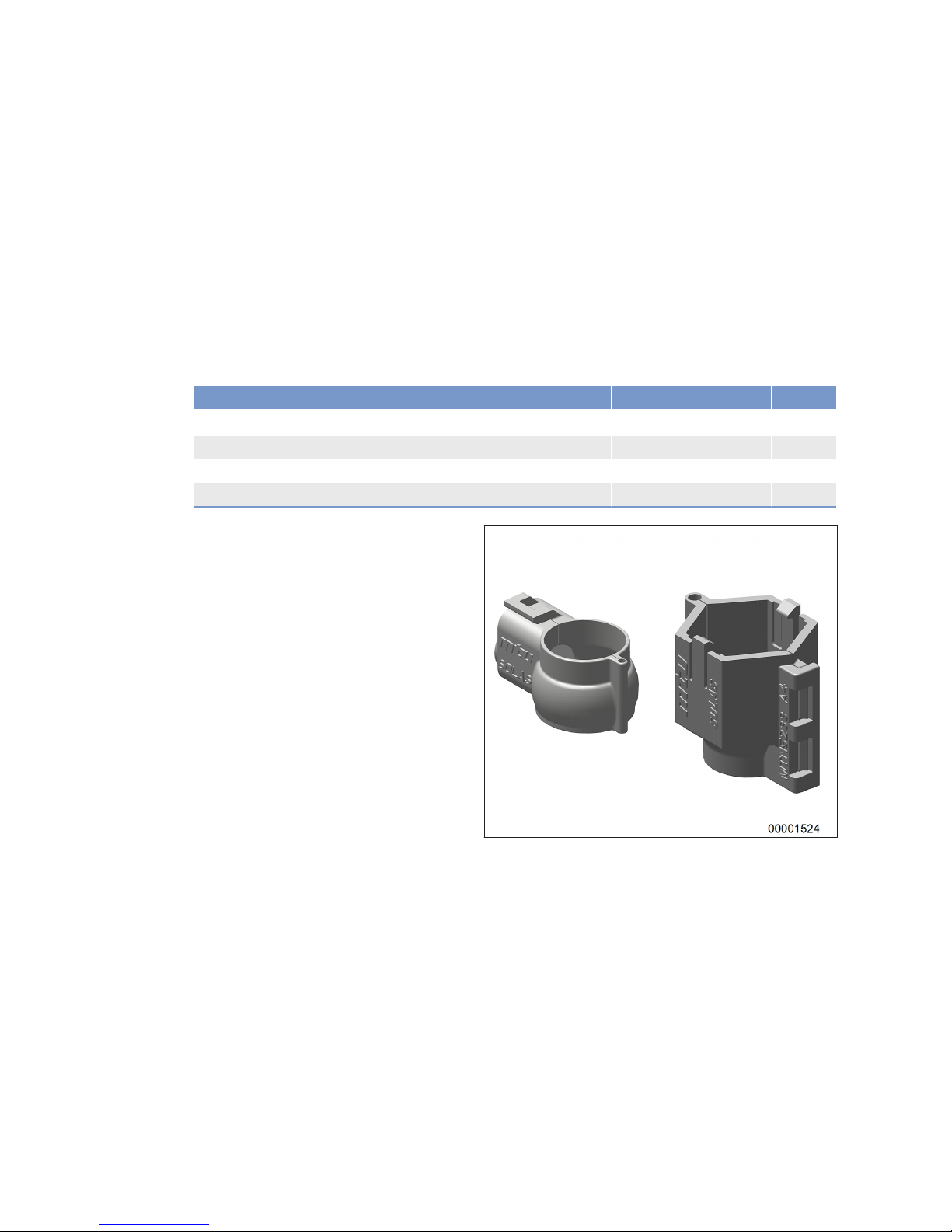
7 Task Description
7.1 SOLAS
7.1.1 SOLAS shielding as per MTN 5233 – Installation
Preconditions
☑Engine is stopped and starting disabled.
Special tools, Material, Spare parts
Designation / Use Part No. Qty.
Shield A4
735233000100 10
Shield A5
735233000101 14
Shield A7
735233000103 6
Shield A8
735233000104 2
SOLAS shielding – Installation
1. Pinpoint installation location (→ Page 70).
2. Install suitable shielding.
3. Press shielding until locked.
68 | Task Description | MS150063/02E 2014-03
TIM-ID: 0000010550 - 003
Page 69
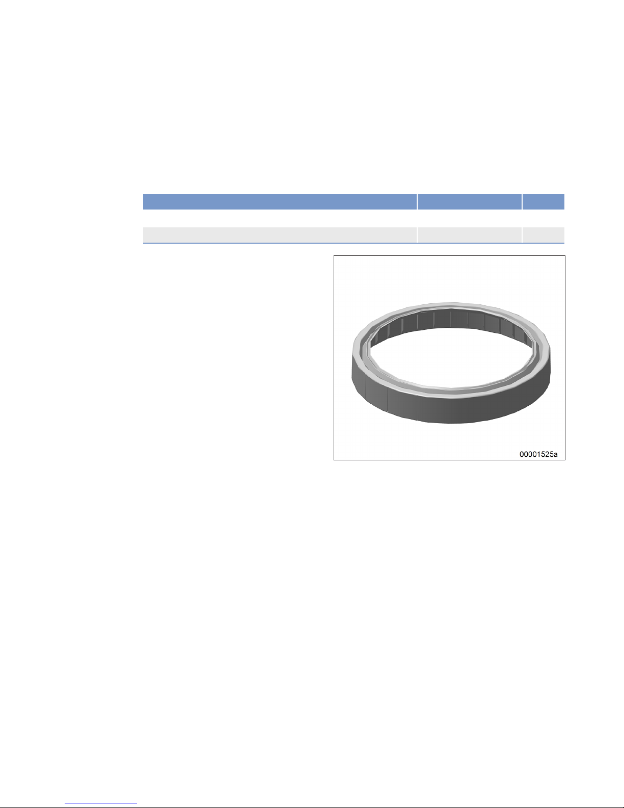
7.1.2 SOLAS shielding – Installation
Preconditions
☑Engine is stopped and starting disabled.
☑Engine is cooled down to ambient temperature.
Special tools, Material, Spare parts
Designation / Use Part No. Qty.
Oil filter shield
X00009628
Fuel filter shield
X00009654
Installing SOLAS shield on oil filter and fuel filter
1. Pinpoint installation location (→ Page 70).
2. Install suitable shielding.
MS150063/02E 2014-03 | Task Description | 69
TIM-ID: 0000010702 - 005
Page 70
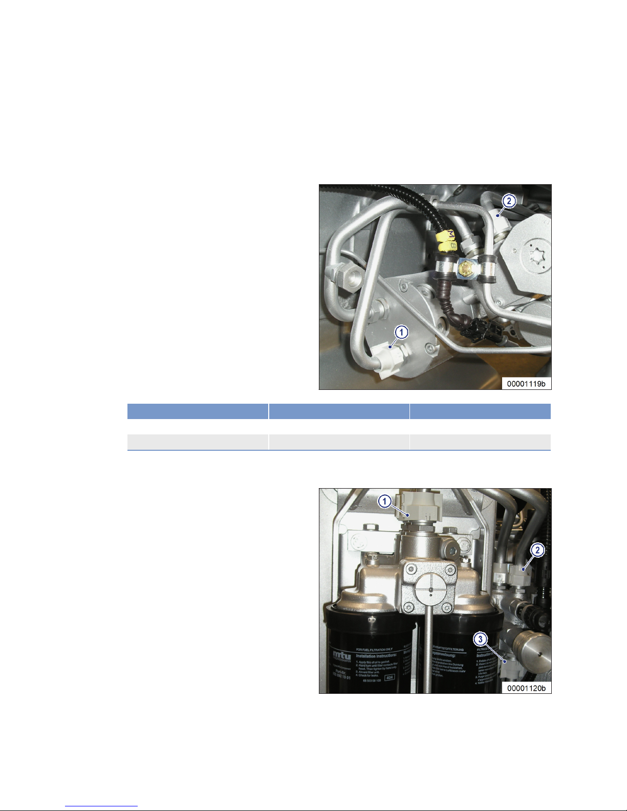
7.1.3 Installation locations for SOLAS shielding
General information
Primarily fit SOLAS shielding as per MTN 5233 (→ Page 68).
Free end B-side
Item Type of shielding Comments
1 (free end, B-side) Shield (A7) On fuel delivery pump
2 (free end, B-side) Shield (A7) On HP fuel pump
Free end
70 | Task Description | MS150063/02E 2014-03
TIM-ID: 0000010064 - 006
Page 71
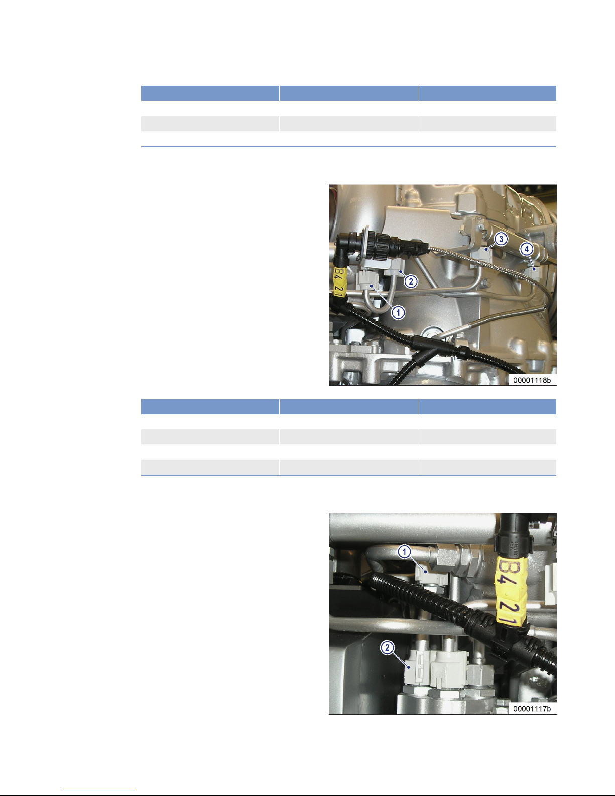
Item Type of shielding Comments
1 (free end) Shield (A8) On fuel filter
2 (free end) Shield (A7) Above fuel priming pump
3 (free end) Shield (A7) Below fuel priming pump
Driving end A-side
Item Type of shielding Comments
1 (Driving end, A-side) Shield (A5) On air flap
2 (driving end, A-side) Shield (A4) On brazed-on union
3 (driving end, A-side) Shield (A5) On turbocharger flap
4 (driving end, A-side) Shield (A5) On turbocharger flap
Driving end A-side
MS150063/02E 2014-03 | Task Description | 71
TIM-ID: 0000010064 - 006
Page 72

Item Type of shielding Comments
1 (Driving end, A-side) Shield (A5) To turbocharger lubrication
2 (driving end, A-side) Shield (A5) On valve plate
Driving end
Item Type of shielding Comments
1 (driving end) Shield (A4) Turbocharger lubrication, left side
2 (driving end) Shield (A4) Turbocharger lubrication, center
Driving end
Item Type of shielding Comments
1 (driving end) Shield (A4) Turbocharger lubrication, right
side
72 | Task Description | MS150063/02E 2014-03
TIM-ID: 0000010064 - 006
Page 73
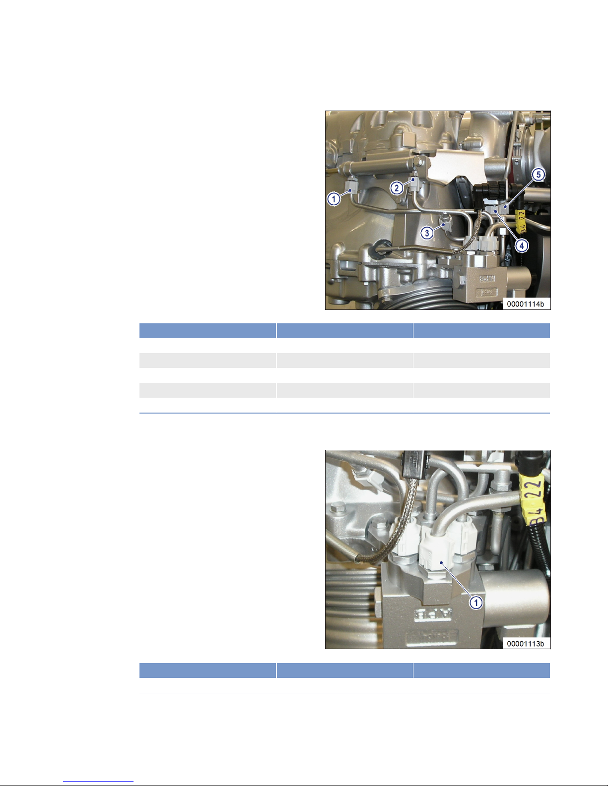
Driving end B-side
Item Type of shielding Comments
1 (driving end, B-side) Shield (A5) Turbocharger flap
2 (driving end, B-side) Shield (A5) Turbocharger flap
3 (driving end, B-side) Shield (A4) On brazed-on union
4 (driving end, B-side) Shield (A5) On air flap
5 (driving end, B-side) Shield (A4) To turbocharger lubrication
Driving end B-side
Item Type of shielding Comments
1 (driving end, B-side) Shield (A5) On valve plate
MS150063/02E 2014-03 | Task Description | 73
TIM-ID: 0000010064 - 006
Page 74
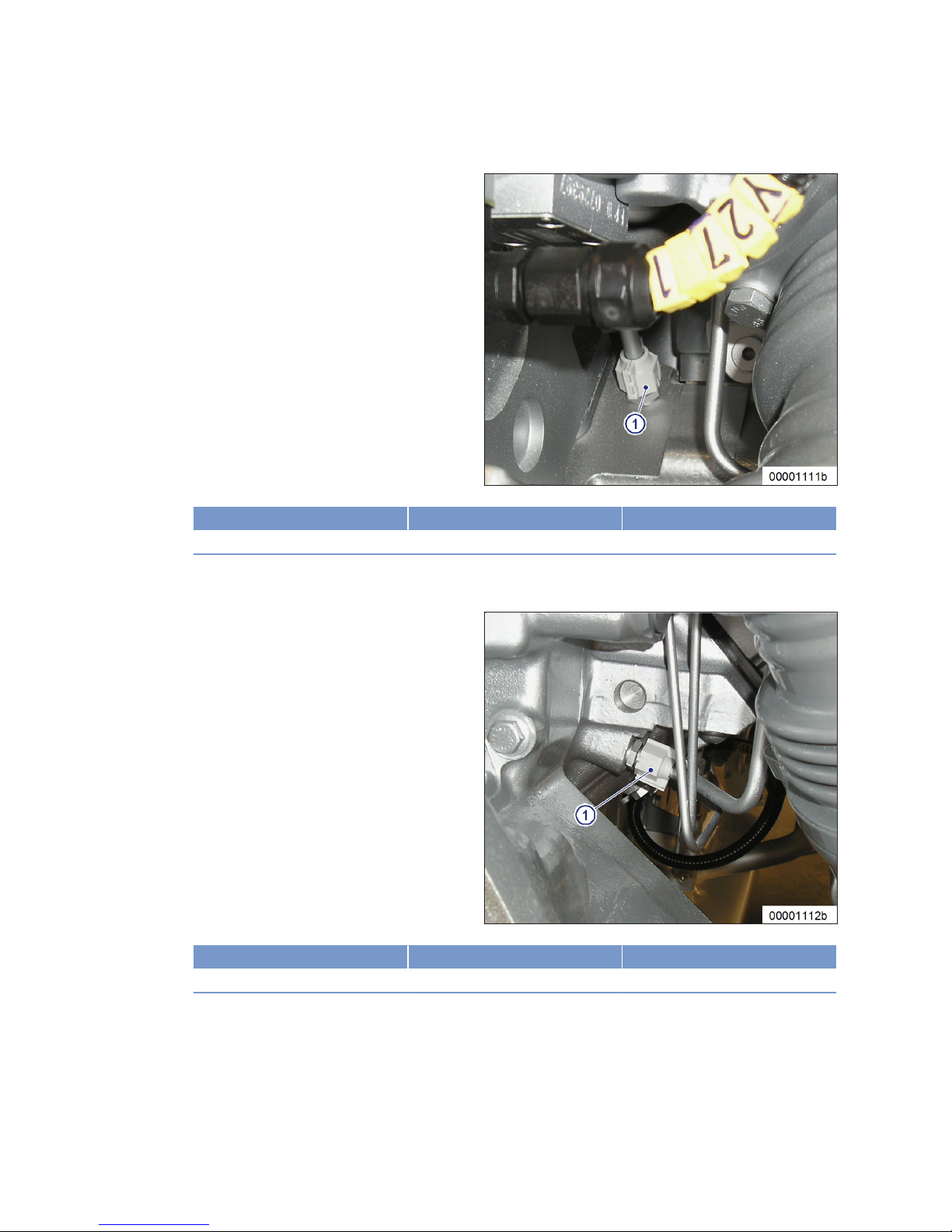
Driving end A-side
Item Type of shielding Comments
1 (Driving end, A-side) Shield (A5) To flap control
Driving end B-side
Item Type of shielding Comments
1 (driving end, B-side) Shield (A5) To flap control
74 | Task Description | MS150063/02E 2014-03
TIM-ID: 0000010064 - 006
Page 75

7.2 Engine
7.2.1 Engine – Barring manually
Preconditions
☑Engine is stopped and starting disabled.
Special tools, Material, Spare parts
Designation / Use Part No. Qty.
Engine barring gear
F6783914 1
Ratchet
F30006212 1
DANGER
Rotating and moving engine parts.
Risk of crushing, danger of parts of the body being caught or pulled in!
• Before barring the engine, make sure that there are no persons in the engine's danger zone.
• After finishing work on the engine, make sure that all safety devices are put back in place and all
tools are removed from the engine.
Barring engine manually
1. Fit ratchet with barring gear on barring gear connection at the vibration damper on engine free end.
2. Rotate crankshaft in engine direction of rotation. Apart from the normal compression resistance, there
should be no resistance.
Result: If the resistance exceeds the normal compression resistance, contact Service.
MS150063/02E 2014-03 | Task Description | 75
TIM-ID: 0000002527 - 004
Page 76
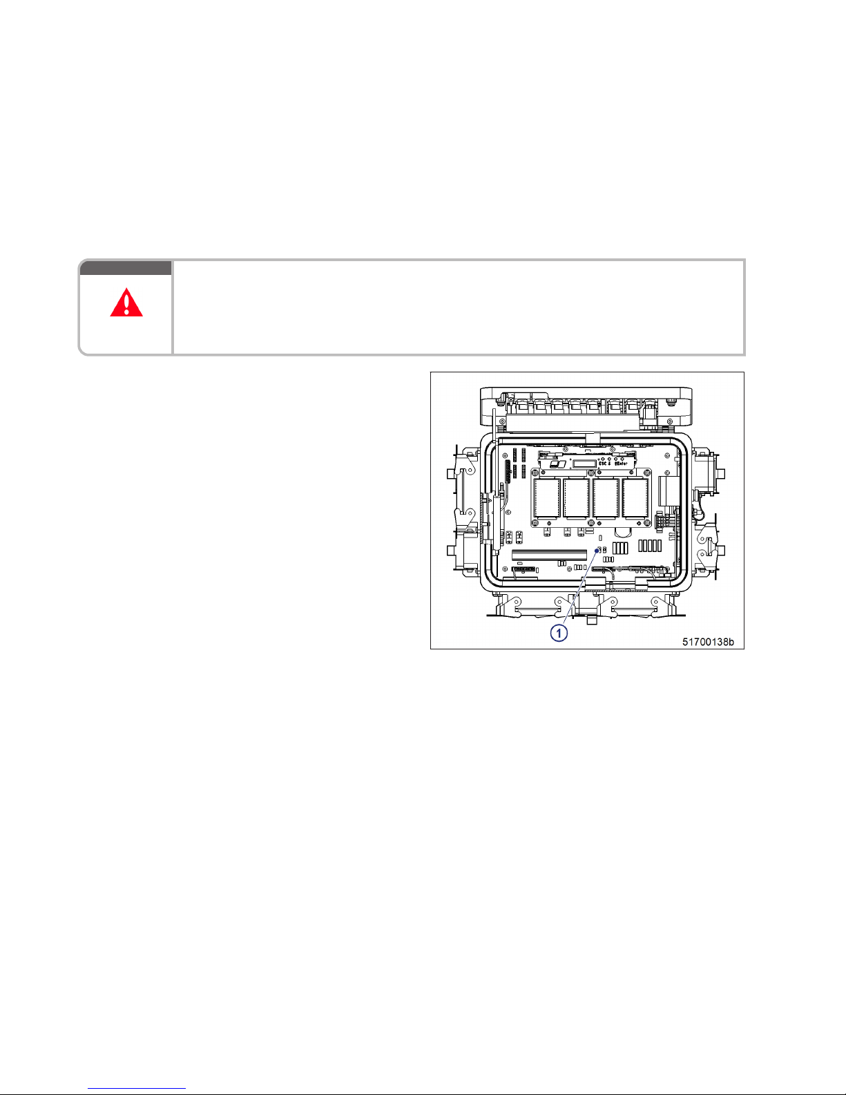
7.2.2 Engine – Cranking on starting system
Preconditions
☑Clutch is disengaged.
☑Engine start is disabled.
☑LOP is accessible and open.
DANGER
Rotating and moving engine parts.
Risk of crushing, danger of parts of the body being caught or pulled in!
• Before barring the engine, make sure that there are no persons in the engine's danger zone.
• After finishing work on the engine, make sure that all safety devices are put back in place and all
tools are removed from the engine.
Turning
1. Press and hold down TURN pushbutton on
LMB motherboard of LOP.
Result: Engine is cranked on starter for max.
20 seconds.
2. Release TURN button.
76 | Task Description | MS150063/02E 2014-03
TIM-ID: 0000002788 - 002
Page 77

7.3 Cylinder Liner
7.3.1 Cylinder liner – Endoscopic examination
Preconditions
☑Engine is stopped and starting disabled
Special tools, Material, Spare parts
Designation / Use Part No. Qty.
Rigid endoscope
Y20097353 1
Preparatory steps
1. Remove cylinder head cover (→ Page 86).
2. Remove injector (→ Page 88).
Positioning crankshaft at BDC
1. Using barring gear, turn crankshaft until crankshaft journal of the cylinder to be inspected has reached
BDC.
2. Insert endoscope into cylinder liner through injector seat.
Cylinder liner – Endoscopic examination
Findings Task
•
Thin carbon coating around circumference of carbon scraper ring
•
Slight localized additive deposits at top edge
•
Localized smooth areas at bottom edge
•
Carbon deposits around circumference between top piston ring and
bottom edge of carbon scraper ring
•
First signs of marks left by top piston ring
•
Bright mark around circumference
•
Faultless, even honing pattern
•
First signs of marks left by lower cooling bores
•
Running pattern seems darker
No action required.
•
Darker areas of even or varying color intensity
•
Beginning and end of the discoloration are not sharply defined and
do not cover the entire stroke area
•
Dark areas in the upper section of the cooling bore, remaining circumference cannot be faulted
•
Piston rings faultless
Further endoscopic examination required as part of maintenance work.
•
On the entire circumference not only bright discoloration (not critical for operation) clearly visible darker stripes that begin at the top
piston ring
•
Heat discoloration in the direction of stroke and honing pattern
damage
•
Heat discoloration of piston rings
Cylinder liner must be replaced,
contact Service.
1. Compile endoscopy report using the table.
2. Use technical terms for description of the liner surface (→ Page 79).
3. Depending on findings:
• Do not take any action or
• Carry out further endoscopic examination as part of maintenance work or
• Contact Service; cylinder liner must be replaced.
MS150063/02E 2014-03
| Task Description | 77
TIM-ID: 0000000015 - 016
Page 78

Final steps
1. Install injector (→ Page 88).
2. Install cylinder head cover (→ Page 86).
78 | Task Description | MS150063/02E 2014-03
TIM-ID: 0000000015 - 016
Page 79

7.3.2 Instructions and comments on endoscopic and visual examination of cylinder
liners
Terms used for endoscopic examination
Use the terms listed below to describe the condition of the cylinder-liner surface in the endoscopic examination report.
Findings Explanations/Action
Minor dirt scores Minor dirt scores can occur during the assembly of a new engine (honing products,
particles, broken-off burrs). Removed cylinders clearly show such scoring on the
running surface under endoscope magnification. Cannot be felt with the fingernail.
Findings not critical.
Single scores Clearly visible scores caused by hard particles. They usually start in the TDC area
and cross through the hone pattern in the direction of stroke.
Findings not critical.
Scored area These areas consist of scores of different length and depth next to one another. In
most cases, they are found at the 6-o'clock and 12-o'clock positions (inlet/
exhaust) along the transverse engine axis.
Findings not critical.
Smoothened area Smoothened areas are on the running surface but almost the whole honing pattern
is still visible. Smoothened areas appear brighter and more brilliant than the surrounding running surface.
Findings not critical.
Bright area Bright areas are on the running surface and show local removal of the honing pat-
tern. Grooves from honing process are not visible any more.
Discoloration This is caused by oxidation (surface discoloration through oil or fuel) and tempera-
ture differences around the liner. It appears rather darker within the honed structure in contrast to the bright metallic running surface. The honing pattern is undisturbed. Discolorations extend in stroke direction and may be interrupted.
Findings not critical.
Corrosion fields /
spots
Corrosion fields / spots result from water (condensed water) with the valves in the
overlap (open) position. They are clearly visible due to the dark color of the honing
groove bottom.
This corrosion is not critical unless there is corrosion pitting.
Black lines Black lines are a step towards heat discoloration. They are visible as a clear discol-
oration from TDC to BDC in the running surface and the start of localized damage
to the honing pattern.
Cylinder liners with a large number of black lines around the running surface have
limited service life and should be replaced.
Burn mark This is caused by a malfunction in the liner / ring tribosystem. Usually they run
over the whole ring-travel area (TDC/BDC), starting at the first TDC-ring and becoming more visible from the second TDC-ring 2 onwards and less pronounced
from TDC-ring 1. The honing pattern is usually no longer visible and displays a
clearly defined (straight) edge to the undisturbed surface. The damaged surface is
usually discolored. The circumferential length varies.
Liners with burn marks, or heat discoloration, starting in TDC-ring 1 have to be replaced.
Seizure marks, scuffing
Irregular circumference lengths and depths. Can be caused either by the piston
skirt or the piston crown. Material deposits on the liner (smear), heavy discoloration. Severe, visible scoring.
Replace liner.
MS150063/02E 2014-03 | Task Description | 79
TIM-ID: 0000000014 - 015
Page 80

Evaluation of findings and further measures
The findings in the start phase of oxidation discoloration and heat discoloration are similar. A thorough
investigation and compliance with the above evaluation criteria allow an unambiguous evaluation. To
avoid unnecessary disassembly work, it is recommended that another inspection be carried out after
further operation of the engine.
80 | Task Description | MS150063/02E 2014-03
TIM-ID: 0000000014 - 015
Page 81

7.4 Crankcase Breather
7.4.1 Crankcase breather – Cleaning oil pre-separator element
Preconditions
☑Engine is stopped and starting disabled.
WARNING
Fuels are combustible.
Risk of fire and explosion!
• Avoid open flames, electrical sparks and ignition sources.
• Do not smoke.
WARNING
Compressed air gun ejects a jet of pressurized air.
Risk of injury to eyes and damage to hearing, risk of rupturing internal organs!
• Never direct air jet at people.
• Always wear safety goggles/face mask and ear defenders.
Crankcase breather – Cleaning
oil pre-separator element
1. Remove cover (5) from housing (4).
2. Take off oil pre-separator element (1), gasket (3) and O-ring (2).
3. Wash oil pre-separator element (1) and
housing (4) in fuel and blow out with compressed air.
4. Moisten oil pre-separator element (1) with
engine oil.
5. Position oil pre-separator element (1) with
new gasket (3) and O-ring (2) on housing
(4) and install cover (5).
6. Clean other oil pre-separator elements in
the same way.
MS150063/02E 2014-03 | Task Description | 81
TIM-ID: 0000011545 - 005
Page 82

7.4.2 Crankcase breather – Oil separator element replacement, diaphragm check and
replacement
Preconditions
☑Engine is stopped and starting disabled.
Special tools, Material, Spare parts
Designation / Use Part No. Qty.
Torque wrench, 6-50 Nm
F30027336 1
Ratchet
F30027340 1
Engine oil
Filter element
(→ Spare Parts Catalog)
Diaphragm
(→ Spare Parts Catalog)
Gasket
(→ Spare Parts Catalog)
WARNING
Hot oil.
Oil can contain combustion residues which are harmful to health.
Risk of injury and poisoning!
• Wear protective clothing, gloves, and goggles / safety mask.
• Avoid contact with skin.
• Do not inhale oil vapor.
Replacing oil separator element
1. Remove cover (2) with O-ring (3).
2. Remove filter element (1) from housing (4).
3. Insert new filter element in housing (4).
4. Install cover (2) with new O-ring.
5. Use torque wrench to tighten the screws of cover (2) to the specified torque.
Name Size Type Lubricant Value/Standard
Screw Tightening torque (Engine oil) 10 Nm −2 Nm
6. Replace further oil separator elements in the same way.
82 | Task Description |
MS150063/02E 2014-03
TIM-ID: 0000000017 - 008
Page 83

Checking diaphragm
1. Remove cover (4).
2. Remove spring (5), gasket (2) and diaphragm (3).
3. Check diaphragm (3) for damage, fit new
diaphragm if used one is damaged.
4. Install diaphragm (3) on housing (1).
5. Install new seal (2) and spring (5) together
with cover (4).
6. Use torque wrench to tighten the screws of cover (4) to the specified torque.
Name Size Type Lubricant Value/Standard
Screw Tightening torque (Engine oil) 10 Nm −2 Nm
7. Check diaphragms in further oil separators in the same way.
MS150063/02E 2014-03 | Task Description | 83
TIM-ID: 0000000017 - 008
Page 84

7.5 Valve Drive
7.5.1 Valve clearance – Check and adjustment
Preconditions
☑Engine is stopped and starting disabled.
☑Engine coolant temperature is max. 40 °C.
☑Valves are closed.
Special tools, Material, Spare parts
Designation / Use Part No. Qty.
Feeler gage
Y4345893 1
Engine barring gear
F6783914 1
Ratchet
F30006212 1
Double-head box wrench
F30002800 1
Offset screwdriver
F30002816 1
Socket wrench
F30030450 1
Torque wrench, 10-60 Nm
F30510423 1
Measuring instrument
Y4345888 1
Preparatory steps
1. Remove air filter (→ Page 102).
2. Remove cylinder head cover (→ Page 86).
Positioning piston of cylinder A1
at TDC
Note: With cylinder head and valve gear installed.
1. Insert preloaded dial gage (2) into measuring device (4) and secure using screw (1).
2. Install measuring device (4) in cylinder
head and secure using knurled-head
screw (3).
3. Zero dial gage (2).
4. Turn engine using barring gear until piston
A1 reaches firing TDC.
Result: The piston is at firing TDC when both rock-
er arms are unloaded, i.e. have clearance.
84 | Task Description | MS150063/02E 2014-03
TIM-ID: 0000050016 - 001
Page 85

Checking valve clearance at two crankshaft positions
1. Check TDC position of piston in cylinder A1:
• If the rocker arms are unloaded on cylinder A1, the piston is in firing TDC.
• If the rocker arms are loaded on cylinder A1, the piston is in overlap TDC.
2. Check valve clearance with cold engine:
• Inlet (I) = 0.3 mm;
• Exhaust (X) = 0.4 mm.
3. Check all valve clearances at two crankshaft positions (firing TDC and overlap TDC) according to the
table below.
Position Cylinder 1 2 3 4 5 6 7 8 9 10
12V
Firing TDC in cylinder A1 Bank A I X I – – X I – – X – –
Bank B I – – – – X I – I X – X
Overlap TDC in cylinder A1 Bank A – – – X I – – X I – I X
Bank B – X I X I – – X – – I –
16V
Firing TDC in cylinder A1 Bank A I X – X I X I – – X I – – – – –
Bank B I – – X – – I – I X I – I X – X
Overlap TDC in cylinder A1 Bank A – – I – I – – X I – – X I X I X
Bank B – X I – I X I X – – – X – – I –
I
Inlet: Inlet valve adjustment admissible
X
eXhaust: Exhaust valve adjustment admissible
–
Valve adjustment inadmissible
4. Use feeler gage to determine the distance between valve bridge and rocker arm.
5. If the deviation from the reference value exceeds 0.1 mm, adjust valve clearance.
Adjusting valve clearance
1. Loosen locknut (1) and unscrew adjusting
screw (2) by a few threads.
2. Insert feeler gage (3) between valve bridge
and rocker arm.
3. Readjust adjusting screw (2) so that the
feeler gage (3) just passes through the gap.
4. Tighten locknut (1) to the specified tightening torque of 50 Nm using a torque wrench
while holding the adjusting screw (2) with
an Allen key.
5. Check that the feeler gage (3) just passes
through between valve bridge and rocker
arm.
Result: If not, adjust valve clearance.
Final steps
1. Remove barring gear.
2. Install cylinder head cover (→ Page 86).
3. Install air filter (→ Page 102).
MS150063/02E 2014-03
| Task Description | 85
TIM-ID: 0000050016 - 001
Page 86
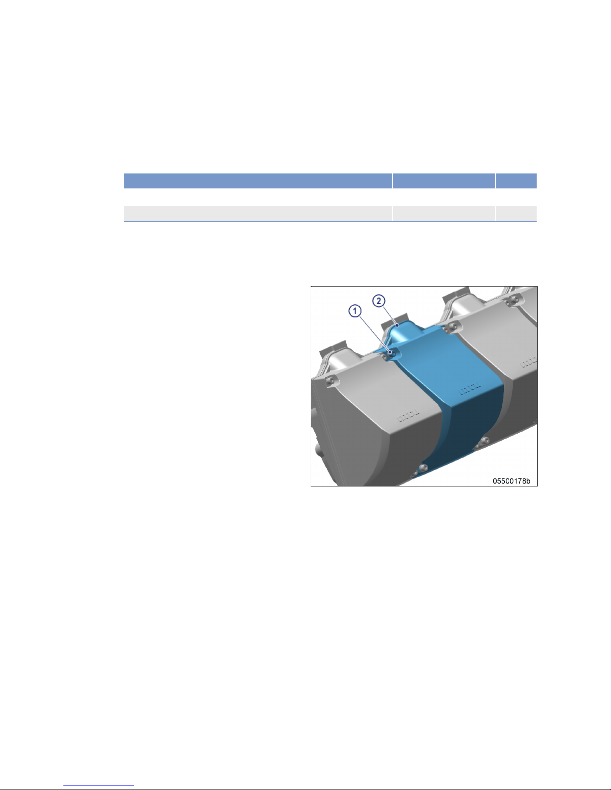
7.5.2 Cylinder head cover – Removal and installation
Preconditions
☑Engine is stopped and starting disabled.
Special tools, Material, Spare parts
Designation / Use Part No. Qty.
Centering jig
F6783025 1
Sealing
(→ Spare Parts Catalog)
Preparatory steps
1. Remove air filter (→ Page 102).
2. Remove air guide housing.
Removing and installing cylinder head cover
1. Remove screws (1).
2. Remove cylinder head cover (2) with gasket from cylinder head.
3. Clean installation surface.
4. Check condition of gasket of cylinder head
cover.
Result: Replace damaged seals.
5. Align cylinder head cover (2) with centering
jig.
6. Tighten screws (1) to specified torque
20 Nm using a torque wrench.
Final steps
1. Install air filter (→ Page 102).
2. Install air guide housing.
3. Check cylinder head covers for leaks.
86 | Task Description | MS150063/02E 2014-03
TIM-ID: 0000004470 - 002
Page 87

7.6 Injection Valve / Injector
7.6.1 Injector – Replacement
Special tools, Material, Spare parts
Designation / Use Part No. Qty.
Injector
(→ Spare Parts Catalog)
Remove injector and install new one.
u (→ Page 88)
MS150063/02E 2014-03 | Task Description | 87
TIM-ID: 0000004642 - 002
Page 88

7.6.2 Injector – Removal and installation
Preconditions
☑Engine is stopped and starting disabled.
Special tools, Material, Spare parts
Designation / Use Part No. Qty.
Socket wrench
0005896803/00 1
Puller
F6790629 1
Double-head box wrench
F30011450 1
Open-end wrench bit
F30025897 1
Box wrench
F30451199 1
Alignment device
F6790507 1
Grease(Kluthe Hakuform 30-11C)
X00059351 1
Engine oil
WARNING
Fuels are combustible.
Risk of fire and explosion!
• Avoid open flames, electrical sparks and ignition sources.
• Do not smoke.
Preparatory steps
1. Close off fuel supply to engine.
2. Remove cylinder head cover (→ Page 86).
Removing injector
1. Remove HP line (5) using socket wrench.
2. Disconnect injector cable (4).
3. Remove screw (2).
4. Take off hold-down clamp (3).
5. Remove injector (1) with puller.
6. Remove O-rings from injector.
7. Mask all connections and bores or seal
with suitable plugs.
88 | Task Description | MS150063/02E 2014-03
TIM-ID: 0000004650 - 003
Page 89

Installing injector
1. Prior to installation, remove all blanking plugs.
2. Fit new O-rings onto injector and coat with grease.
3. Fit new sealing ring with grease on injector, observe installation position of sealing ring.
4. Clean sealing surface on cylinder head and protective sleeve.
5. Insert injector (1) in cylinder head, ensuring that it is correctly aligned with the HP line connection.
6. Fit hold-down clamp (3) in correct installation position, coat screw (2) with engine oil.
7. Screw in screw (2) and tighten by hand.
8. Coat thread and sealing cone of HP line (5) and injector (1) with engine oil.
9. Align injector (1) and HP line (5) with alignment jig.
10. Connect HP line (5) to HP accumulator and tighten by hand.
11. Connect HP line (5) to injector (1) and tighten by hand.
12. Tighten screw of hold-down clamp (3) with a box wrench adapter and a torque wrench to specified
tightening torque.
Name Size Type Lubricant Value/Standard
Screw M10 x 85 Tightening torque (Engine oil) 40 Nm + 4 Nm
13. Use socket wrench and torque wrench to tighten HP line (5) to the specified torque.
Name Size Type Lubricant Value/Standard
HP line Tightening torque (Engine oil) 30 Nm + 5 Nm
14. Attach cable (4).
Final steps
1. Install cylinder head cover (→ Page 86).
2. Open up fuel supply to engine.
MS150063/02E 2014-03 | Task Description | 89
TIM-ID: 0000004650 - 003
Page 90
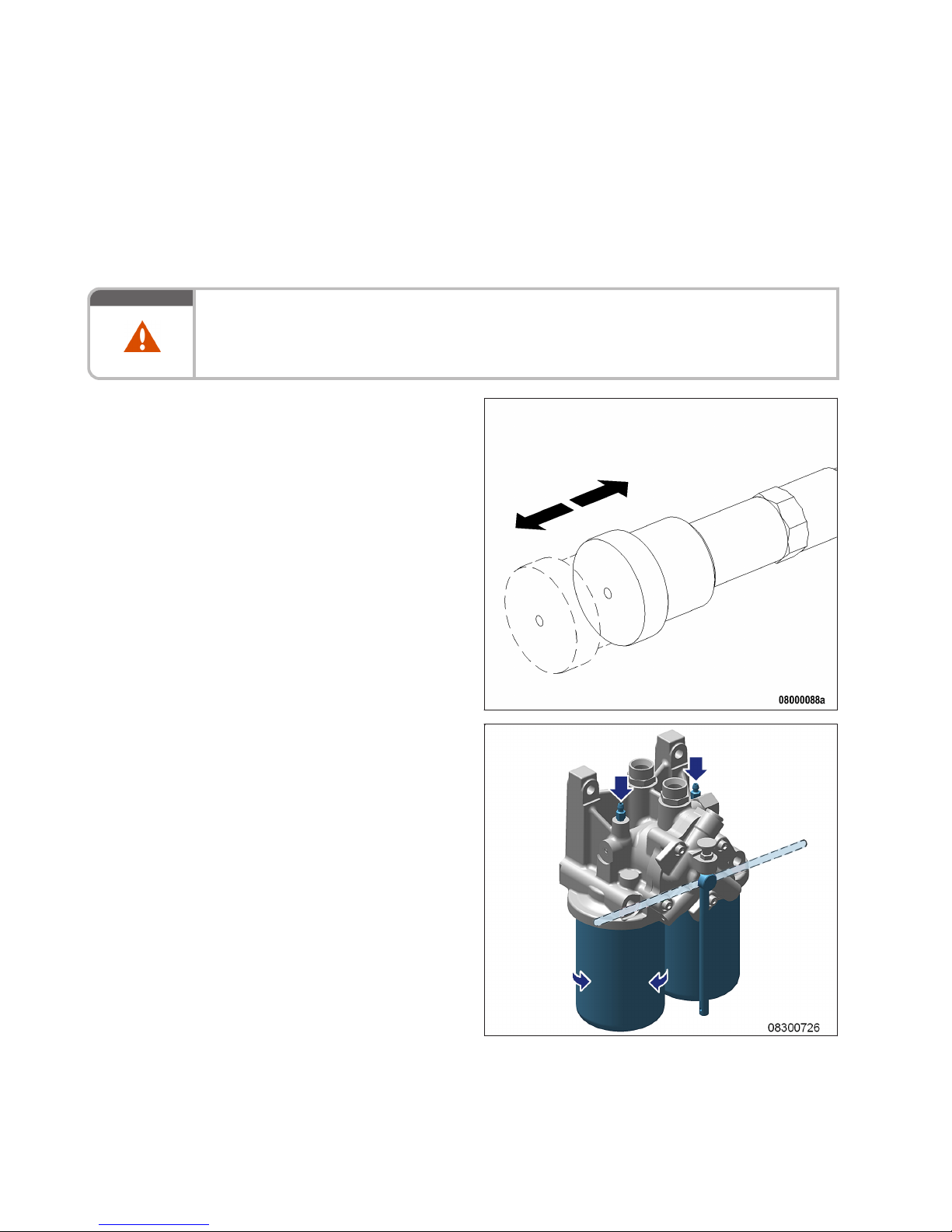
7.7 Fuel System
7.7.1 Fuel system – Venting
Preconditions
☑Engine is stopped and starting disabled.
WARNING
Fuels are combustible.
Risk of fire and explosion!
• Avoid open flames, electrical sparks and ignition sources.
• Do not smoke.
Venting fuel system
1. Unlock fuel priming pump, unscrew handle.
2. Open vent plugs on filter head.
Note: New version has two threaded vent plugs,
old version has four threaded vent plugs.
3. Operate the pump with the handle until fuel
without bubbles comes out of the vent
plugs and the nipples.
4. Close vent plugs on filter head.
5. Operate the pump with the handle until fuel
without bubbles comes out of the nipple.
6. Lock fuel priming pump, screw in handle.
90 | Task Description | MS150063/02E 2014-03
TIM-ID: 0000004716 - 002
Page 91
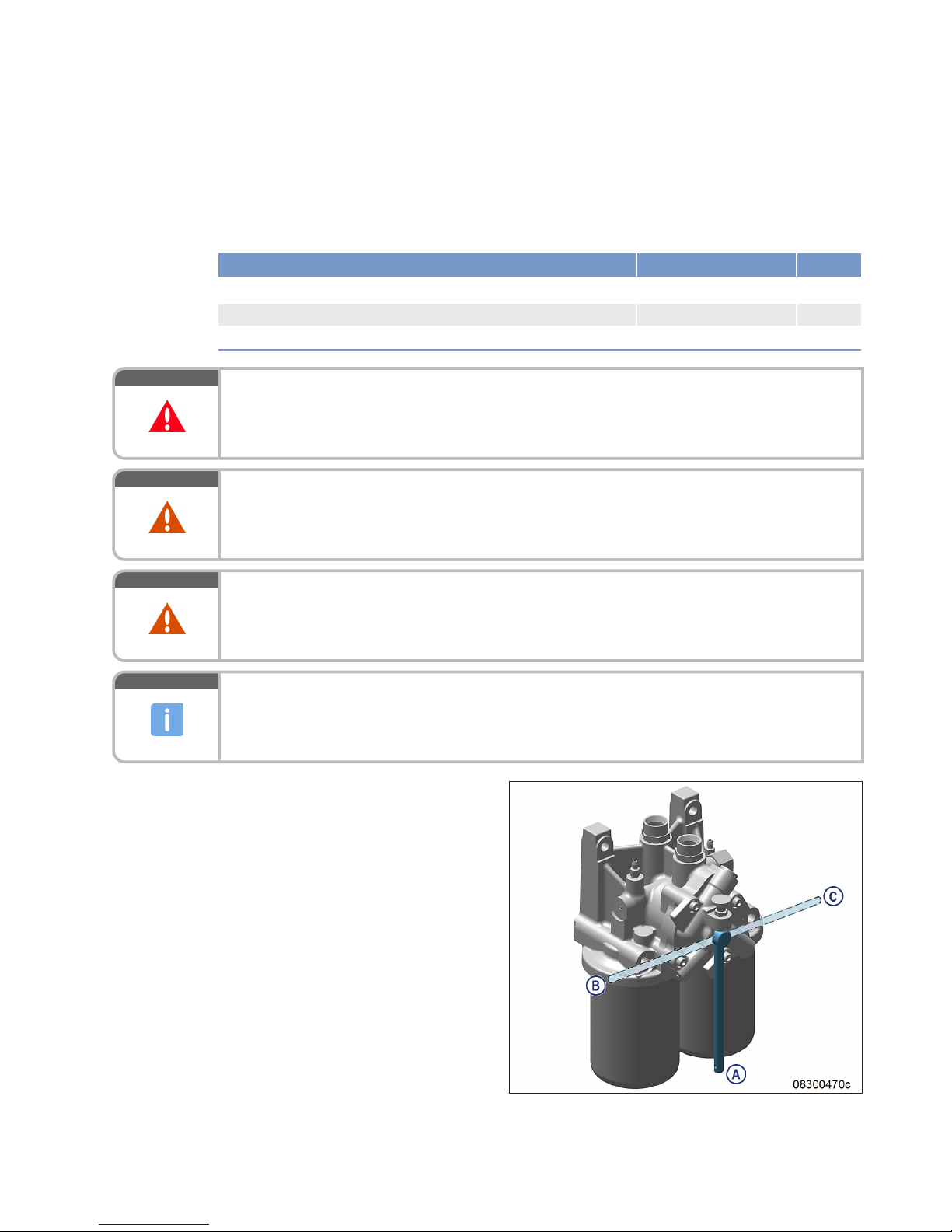
7.8 Fuel Filter
7.8.1 Fuel filter – Replacement
Special tools, Material, Spare parts
Designation / Use Part No. Qty.
Oil filter wrench
F30379104 1
Diesel fuel
Easy-change filter
(→ Spare Parts Catalog)
DANGER
Rotating and moving engine parts.
Risk of crushing, danger of parts of the body being caught or pulled in!
• Only run the engine at low power. Keep away from the engine's danger zone.
WARNING
Fuels are combustible.
Risk of fire and explosion!
• Avoid open flames, electrical sparks and ignition sources.
• Do not smoke.
WARNING
High level of engine noise when the engine is running.
Risk of damage to hearing!
• Wear ear protectors.
NOTICE
Damage to component!
Severe material damage!
• For filter replacement with the engine running, operate the engine at low engine load.
• The filter which is to be replaced must be cut out for a brief period only.
Replacing easy-change fuel filter
replacement with the engine
stopped
1. Stop engine and disable engine start.
2. Cut out the filter to be replaced.
B Left filter is cut out
C Right filter is cut out
3. Remove cut-out easy-change filter using
the oil filter wrench.
4. Clean sealing surface on filter head.
5. Check sealing ring of the new easy-change
filter and coat it with fuel.
6. Fit SOLAS shield (→ Page 68).
7. Screw on easy-change filter and tighten by
hand.
8. Set three-way cock to operating position
(A) so that both filters are cut in (operating
position).
9. Replace further fuel filters in the same way.
10. Vent fuel system (→ Page 90).
MS150063/02E 2014-03 | Task Description | 91
TIM-ID: 0000004914 - 005
Page 92

Replacing easy-change fuel filter
with the engine running
1. Cut out the filter to be replaced.
2. Open the threaded vent plugs at the filter
head of the cut-out filter and make sure
that the fuel filter is not pressurized.
Note: New version has two threaded vent plugs,
old version has four threaded vent plugs.
3. Close threaded vent plugs.
4. Remove cut-out easy-change filter using
the oil filter wrench.
5. Clean sealing surface on filter head.
6. Check sealing ring of the new easy-change
filter and coat it with fuel.
7. Fit SOLAS shield (→ Page 68).
8. Screw on easy-change filter and tighten by
hand.
9. Set three-way cock to operating position
(both filters cut in).
10. Replace further fuel filters in the same way.
92 | Task Description | MS150063/02E 2014-03
TIM-ID: 0000004914 - 005
Page 93
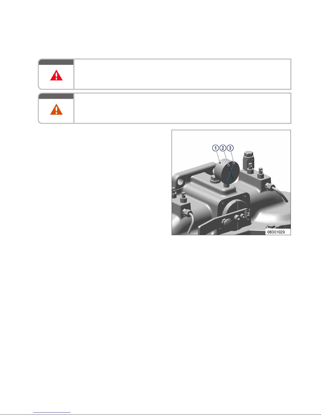
7.8.2 Fuel prefilter – Differential pressure check and adjustment of gauge
DANGER
Rotating and moving engine parts.
Risk of crushing, danger of parts of the body being caught or pulled in!
• Only run the engine at low power. Keep away from the engine's danger zone.
WARNING
High level of engine noise when the engine is running.
Risk of damage to hearing!
• Wear ear protectors.
Setting adjustable pointer of differential pressure gauge
1. After installation of a new filter element,
align adjustable pointer (2) with pressureindicating pointer (3) of pressure gauge (1).
2. Verify that differential pressure is within
the limit.
Fuel prefilter – checking differential pressure
1. With the engine running at full load or rated power, read off pressure at gauge (1).
2. If differential pressure as indicated between position of adjustable pointer (2) and pressure-indicating
pointer (3) of pressure gauge is ≥ 0.3 bar, flush filter element of the cut-in filter (→ Page 96).
MS150063/02E 2014-03 | Task Description | 93
TIM-ID: 0000045555 - 001
Page 94
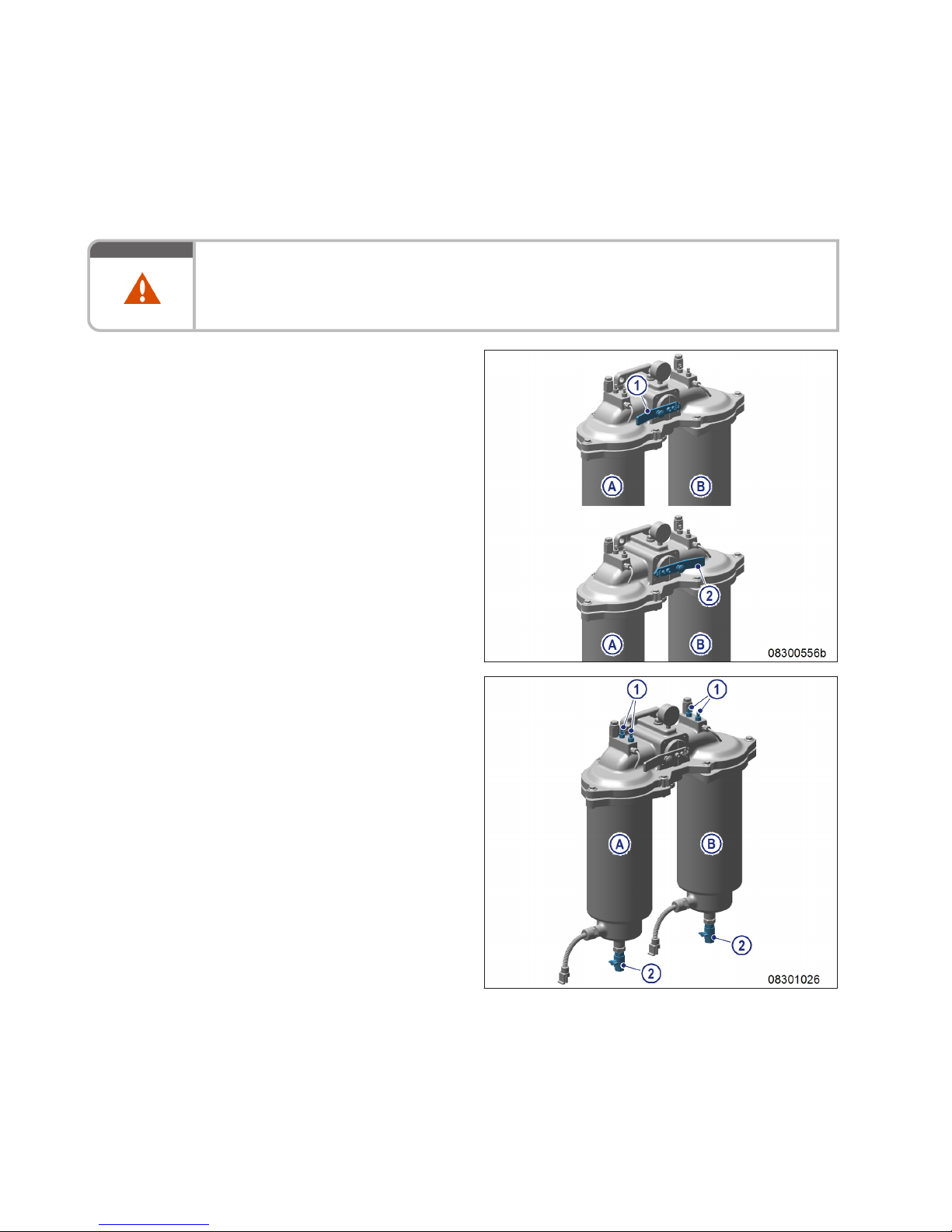
7.8.3 Fuel prefilter – Draining
Preconditions
☑Engine is stopped and starting disabled.
WARNING
Fuels are combustible.
Risk of fire and explosion!
• Avoid open flames, electrical sparks and ignition sources.
• Do not smoke.
Draining fuel prefilter
1. Switch off filter which is to be drained (A or
B):
1 Filter A switched off
2 Filter B switched off
2. Open threaded vent plug (1) of the filter to
be drained.
3. Open drain valve (2).
4. Drain water and contaminants from the filter until pure fuel emerges.
5. Close drain valve (2).
94 | Task Description | MS150063/02E 2014-03
TIM-ID: 0000045553 - 002
Page 95

6. Connect filling pump to filling connection
(1) on suction side of filter.
7. Open vent valve (2) and fill with fuel until it
emerges from the vent pipe (3).
8. Close vent valve (2).
9. Turn slide (4) a little (approx. 30°) and
open vent valve(s) (2) until fuel emerges
from the vent pipe (3).
10. Close vent valve(s) (2).
11. Turn slide (4) back to the locked position.
MS150063/02E 2014-03 | Task Description | 95
TIM-ID: 0000045553 - 002
Page 96

7.8.4 Fuel prefilter – Flushing
Special tools, Material, Spare parts
Designation / Use Part No. Qty.
Diesel fuel
DANGER
Rotating and moving engine parts.
Risk of crushing, danger of parts of the body being caught or pulled in!
• Only run the engine at low power. Keep away from the engine's danger zone.
WARNING
Fuels are combustible.
Risk of fire and explosion!
• Avoid open flames, electrical sparks and ignition sources.
• Do not smoke.
WARNING
High level of engine noise when the engine is running.
Risk of damage to hearing!
• Wear ear protectors.
Flushing fuel prefilter
1. Cut out contaminated filter (A or B):
1 Filter A cut out
2 Filter B cut out
96 | Task Description | MS150063/02E 2014-03
TIM-ID: 0000042959 - 003
Page 97
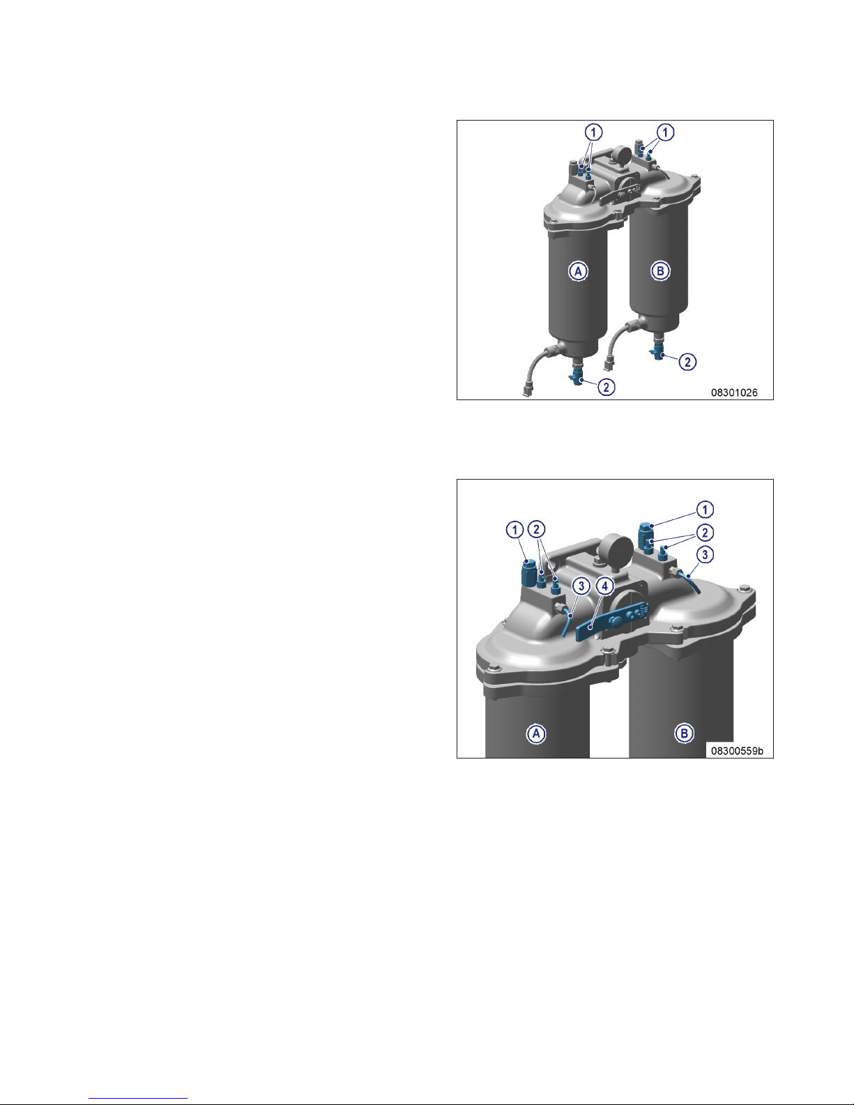
2. Open threaded vent plug (1) of filter to be
flushed.
3. Open drain valve (2) and drain fuel.
Result: Fuel flows from filtered side back to the un-
filtered side, flushing the filter deposits
downwards out of the filter.
4. Close threaded vent plug (1) and drain
valve (2).
Filling fuel prefilter with fuel
1. Stop engine (→ Page 58) and disable engine start.
2. Connect filling pump to filling connection (1) on the intake side of the filter.
3. Open vent valve (2) and fill with fuel until
fuel emerges from the vent pipe (3).
4. Close vent valve (2).
5. Open rotary slide valve (4) a little (by approx. 30°) and open vent valve(s) (2), until
fuel emerges from the vent pipe (3).
6. Close vent valve(s) (2).
7. Turn rotary slide valve (4) back to locked
position.
8. Check differential pressure (→ Page 93).
Result: If flushing did not improve differential pres-
sure, replace filter element in fuel prefilter
(→ Page 98).
MS150063/02E 2014-03 | Task Description | 97
TIM-ID: 0000042959 - 003
Page 98

7.8.5 Fuel prefilter – Filter element replacement
Preconditions
☑Engine is stopped and starting disabled.
Special tools, Material, Spare parts
Designation / Use Part No. Qty.
Diesel fuel
Filter element
(→ Spare Parts Catalog)
Sealing
(→ Spare Parts Catalog)
WARNING
Fuels are combustible.
Risk of fire and explosion!
• Avoid open flames, electrical sparks and ignition sources.
• Do not smoke.
Replacing filter element
1. Switch off filter which is to be changed (A
or B):
1 Filter A switched off
2 Filter B switched off
98 | Task Description | MS150063/02E 2014-03
TIM-ID: 0000045554 - 002
Page 99
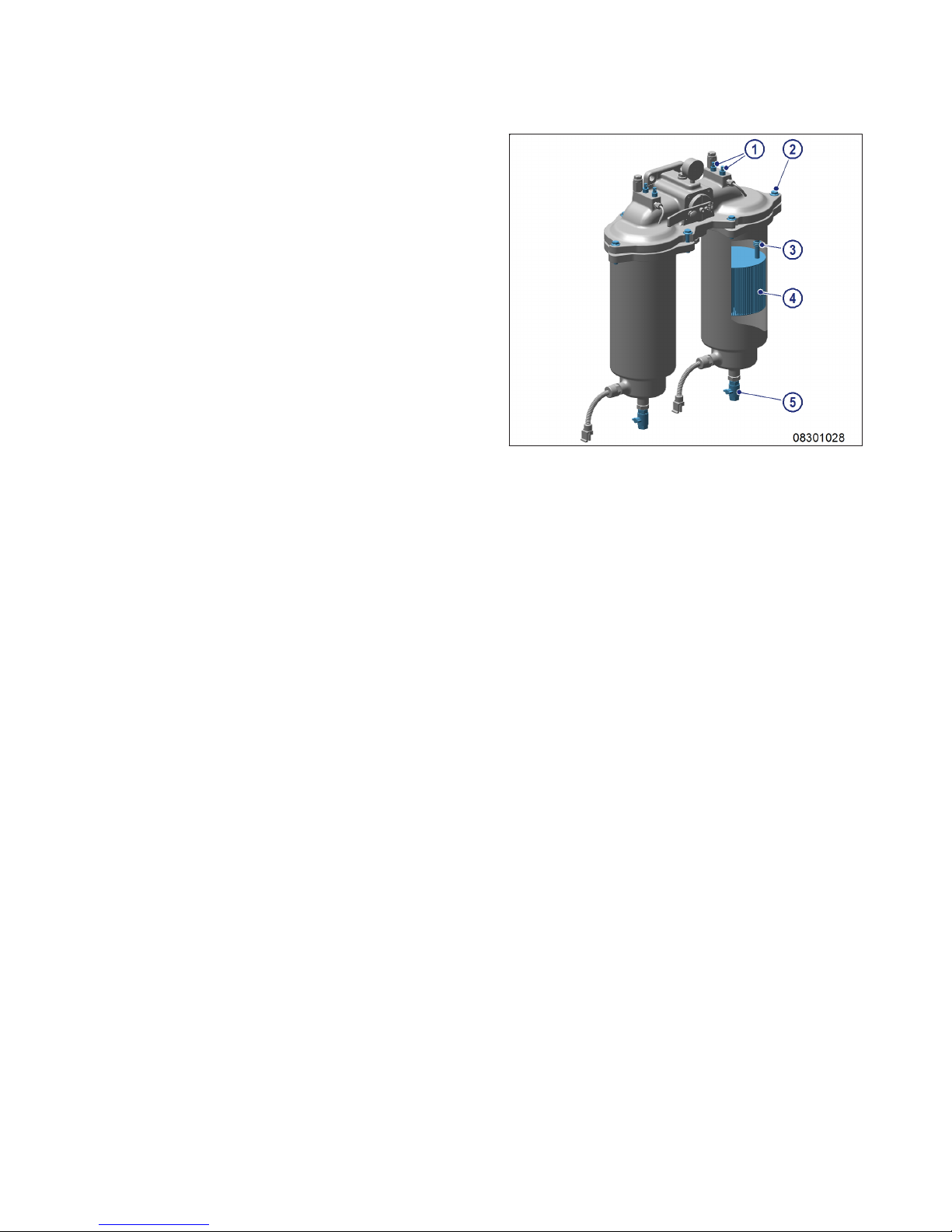
2. Open threaded vent plug (1) of contaminated filter.
3. Unlock drain valve (5) by pressing toggle
and open it.
4. Drain water and dirt from filter.
5. Close drain valve (5).
6. Remove screws securing cover (2) and take
off cover.
7. Remove spring cartridge (3) and filter element (4).
8. Insert new filter element (4) and spring cartridge (3).
9. Fill filter housing with clean fuel.
10. Place new seal in cover.
11. Fit cover with gasket and secure it with
screws (2).
12. Cut in the cut-out filter again.
13. Close threaded vent plug (1) when fuel
emerges.
14. Set adjustable pointer of differential pressure gage (→ Page 93).
MS150063/02E 2014-03 | Task Description | 99
TIM-ID: 0000045554 - 002
Page 100

7.9 Charge-Air Cooling
7.9.1 Intercooler – Checking condensate drain line for coolant discharge and
obstruction
DANGER
Rotating and moving engine parts.
Risk of crushing, danger of parts of the body being caught or pulled in!
• Only run the engine at low power. Keep away from the engine's danger zone.
WARNING
High level of engine noise when the engine is running.
Risk of damage to hearing!
• Wear ear protectors.
WARNING
Compressed air gun ejects a jet of pressurized air.
Risk of injury to eyes and damage to hearing, risk of rupturing internal organs!
• Never direct air jet at people.
• Always wear safety goggles/face mask and ear defenders.
Intercooler – Checking condensate drain line for coolant discharge and obstruction
1. Check drain line for water discharge and
obstruction when the engine is running
idle.
2. If no air emerges, remove condensate drain
line and blow out with compressed air.
3. Replace obstructed drain line by new one.
4. Install condensate drain line.
5. If a large amount of coolant is continuously
discharged, the intercooler is leaking. Contact Service.
Emergency measures prior to engine start with a leaking intercooler
1. Remove injectors (→ Page 87).
2. Bar engine manually (→ Page 75).
3. Crank engine on starting system to blow out combustion chambers (→ Page 76).
4. Install injectors (→ Page 88).
100 | Task Description |
MS150063/02E 2014-03
TIM-ID: 0000027574 - 004
 Loading...