

Page 1

Operation Manual
TFIR-31LAN series
TFIR-31LAN / -31LAN-H
Fixed mount 1D/2D Image Reader
2012/06/13
1st Edition
Page 2

Update Information
Edition
Date Update Contents
1
st
edition 2012/06/13 New release
Page 3

- 1 -
Page 4

- 2 -
Introduction
Thank you for purchasing this product.
This manual explains the specifications, setup, Installation, features, operation, and
system configuration, of the TFIR-31LAN series image reader.
In order to use the product properly, please read this manual carefully.
If any problems are encountered during normal use, please document it carefully to
ensure our support team can accurately reproduce the situation.
The contents of this manual may change without notice. Please check our website
for the most current version.
Safety notices
DO NOT disassemble. Disassembly will void the warranty and could cause damage
or personal injury.
Ensure to follow all warnings or notices displayed by the host computer.
If smoke or odors begin to emit from the product, stop using and disconnect the unit
immediately.
Page 5
- 3 -
DO NOT use AC adapters other than the one recommended. Adapters with differing
voltage or polarity may damage the unit.
MARS TOHKEN SOLUTION products are not designed or intended for the use as a
component in life support appliances or as surgical implants nor in any other
application where failure of the product could cause personal injury or death. The
use of
MARS TOHKEN SOLUTION products shall indemnify and hold harmless to
MARS TOHKEN SOLUTION’s and its shareholders against any claims of injury or
death associated with unintended authorized use.
Handle with care
¾ DATA BACKUP
This product has a memory backup function. This backup data restoration cannot be
guaranteed if repair, reconstruction, or upgrades are performed on this product.
¾ DO NOT use this product at temperature or humidity ranges beyond that documented
in the product specifications, or in direct sunlight.
¾ DO NOT expose this product to water, moisture, oil, etc.
¾ This product may be damaged in environments containing corrosive gas.
¾ DO NOT use any chemicals when cleaning.
To clean the reading window, please follow the steps below:
- Wipe lightly with cloth or swab (may be damp with alcohol).
- Wipe off any residual alcohol using a dry cloth.
Page 6

- 4 -
¾ This is a high-precision optical device, avoid exposing this product to excessive force
such as that sustained by a drop.
Do not install electrical wiring or plugin/unplug of cable (except LAN cable) when this
product is powered on. These may result in an electrical damage to this product.
Locations for operation and storage
Avoid the following locations that could cause an accident or damage to the product.
- Exposed to ambient temperature outside the rating
- Exposed to relative humidity outside the rating
- Exposed to rapid temperature fluctuations (causing condensation)
- Exposed to direct sunlight or near heaters
- Exposed to direct vibration or shock
- In the presence of dust, salt, or iron particles
- In environments where static electricity can build into siginificant charges
- In the presence of flammable or explosive gases
- In the presence of corrosive gas
Long-term storage
Store away from direct sunlight and direct vibration or shock for long term storage.
Do not store this product at temperature or humidity ranges beyond that documented
in the product specifications.
Page 7

- 5 -
Unpacking
Before unpacking the TFIR-31LAN series image reader check that there has been
no damage to the packaging.
Check that the box includes the items listed below. If any items are missing or
damaged, please contact your local sales representative.
Included items
Item Qty
TFIR-31LAN series image reader 1 pcs
Page 8

- 6 -
Table of Contents
INTRODUCTION......................................................................................................................... 2
SAFETY NOTICES...................................................................................................................... 2
HANDLE WITH CARE................................................................................................................3
LOCATIONS FOR OPERATION AND STORAGE .................................................................... 4
LONG-TERM STORAGE............................................................................................................. 4
UNPACKING ............................................................................................................................... 5
1 OVERVIEW........................................................................................................................... 9
1.1 SUPPORTED SYMBOLOGIES........................................................................................... 10
1.2 PRODUCT DESCRIPTION ............................................................................................... 11
2 CONFIGURATION............................................................................................................. 17
2.1 PREPARATION ............................................................................................................... 17
2.2 READING FLOW............................................................................................................. 18
2.3 COMMUNICATION PORT SELECTION (RS232C, LAN) ................................................... 19
2.4 CONFIGURATION........................................................................................................... 19
2.5 TRANSFER IMAGE DATA ................................................................................................ 19
3 OPERATION MODE .......................................................................................................... 20
3.1 SINGLE READING MODE ............................................................................................... 21
3.2 READING TIMEOUT MODE ............................................................................................ 23
3.3 EXTERNAL TRIGGER MODE .......................................................................................... 27
3.4 CONTINUOUS READING MODE ..................................................................................... 29
3.5 TEST MODE .................................................................................................................. 29
3.6 CYCLE BUFFER FUNCTION ........................................................................................... 30
3.7 AUTOSENSE MODE ....................................................................................................... 31
4 CONFIGURATION FOR SYMBOL READING................................................................. 36
4.1 CONFIGURATION PARAMETERS..................................................................................... 36
4.2 CAMERA CONTROL MODE............................................................................................. 39
4.3 DETAIL OF TABLE MODE .............................................................................................. 41
5 ADVANCED FUNCTIONS ................................................................................................ 43
5.1 PRESET MODE .............................................................................................................. 43
5.2 OUTPUT ADDITIONAL INFORMATION............................................................................. 47
Page 9

- 7 -
5.3 SAVE IMAGE ................................................................................................................. 52
5.4 OUTPUT TRACE INFORMATION...................................................................................... 55
5.5 AUTOMATIC TUNING FOR CAMERA SETTINGS................................................................ 61
6 LAN(TCP/IP) CONNECTION ............................................................................................ 62
6.1 PREPARATION ............................................................................................................... 62
6.2 CONFIGURE IP ADDRESS .............................................................................................. 62
6.3 DEFAULT SETTINGS ...................................................................................................... 63
6.4 CHECK FOR LAN SETTINGS.......................................................................................... 65
6.5 CONNECT TO LAN........................................................................................................ 66
6.6 MANAGE COMMUNICATION STATUS .............................................................................. 66
6.7 SERIAL COMMAND FOR LAN SETTINGS ........................................................................ 67
6.8 INITIALIZE LAN SETTINGS ........................................................................................... 68
7 SERIAL COMMAND (RS232C, LAN)................................................................................ 69
7.1 COMMUNICATION ......................................................................................................... 70
7.2 SYMBOLOGIES .............................................................................................................. 71
7.3 SYMBOL READING ........................................................................................................ 79
7.4 CAMERA CONTROL (1) (FOR FIXED GAIN AND AUTOMATIC GAIN CONTROL MODE)..... 81
7.5 CAMERA CONTROL (2) (FOR TABLE MODE) .................................................................. 82
7.6 CAMERA CONTROL (3) (FOR TABLE MODE) .................................................................. 82
7.7 DEFAULT TABLE SETTINGS (*)...................................................................................... 83
7.8 IMAGE PREPROCESSING ............................................................................................... 84
7.9 PRESET MODE .............................................................................................................. 85
7.10 CONFIGURATION REFERENCE....................................................................................... 85
7.11 IMAGE OUTPUT, IMAGE SAVE........................................................................................ 85
7.12 LAN SETTINGS............................................................................................................. 86
7.13 GENERAL OPERATION .................................................................................................. 86
7.14 TABLE OF CHARACTER CODE........................................................................................ 87
8 SPECIFICATIONS ............................................................................................................. 88
8.1 DIMENSIONS................................................................................................................. 90
8.2 INTERFACE ................................................................................................................... 91
8.3 READING RANGE .......................................................................................................... 93
9 EXAMPLE OF CONFIGURATION DIAGRAM................................................................. 95
10 TROUBLESHOOTING ................................................................................................... 96
Page 10

- 8 -
10.1 THE READER DOES NOT START UP OR CANNOT COMMUNICATE WITH A PC................... 96
10.2 SYMBOL CANNOT BE DECODED ..................................................................................... 97
10.3 FAIL TO COMMUNICATE THROUGH TCP/IP PROTOCOL ................................................. 98
10.4 AFTER GOOD READ, THE READER EMITS 7 SHORT BEEPS A FEW SECONDS LATER. ....... 98
Page 11

- 9 -
1 Overview
(1) TFIR-31LAN series image reader is fixed mount (stationary type) image reader capable
of reading both linear (1D) bar codes and two-dimensional (2D) codes. These units
incorporate the most innovative digital camera technologies, related image recognition,
and processing software. The image reader can read both 1D and 2D symbols, with auto
discrimination of symbol type and omni-directional (360-degree rotation) reading. This
manual may also refer to 1-dimensional and 2-dimensional barcodes as “symbols”.
(2) The TFIR-31LAN series image reader has RS232C and Ethernet (10BASE-T) interface,
and can be connected easily to a Windows PC.
Windows 2000, Windows XP, Windows Vista and Windows 7 are supported.
z Windows is a registered trademark or trademark of Microsoft Corporation in the United States or
other countries.
z If the image reader does not work in your system environment with Windows PC, please contact
your local sales representative.
(3) The TFIR-31LAN series image reader incorporates functionality to read DPM symbols
(Direct part marking symbols) which are printed directly on objects such as Laser marking
and Dot Peen Marking.
Image Preprocessing:
This function uses MARS TOHKEN SOLUTION’s latest image processing
algorithms to improve deteriorated pictures to provide the user with the best
reading performance.
Table Mode:
Combining multiple functions (Shutter Speed, Gain, Image Processing, etc),
this function executes the image capture and image processing automatically
in the order appointed to maximum of 8 configurations.
(4) If there are any difficulties configuring the input SYNC signal to a proper timing, please
use the MAXIMG function to continuously capture images during the configuration period.
Page 12

- 10 -
(5) The TFIR-31LAN series image reader has two types of internal illumination source as
follows.
TFIR-31LAN-H : Spot illumination source and diffused illumination source
TFIR-31LAN : Spot illumination source A and spot illumination source B
1.1 Supported Symbologies
1D bar codes:
Code39
Code128
EAN128
Codabar
ITF (interleaved 2 of 5)
JAN / EAN / UPC
Code93
RSS
2D codes:
Data Matrix (ECC200)
QR Code, Micro QR
PDF 417, Micro PDF
Maxi Code
Composite
Postal (Japan Post)
Aztec Code
Page 13
- 11 -
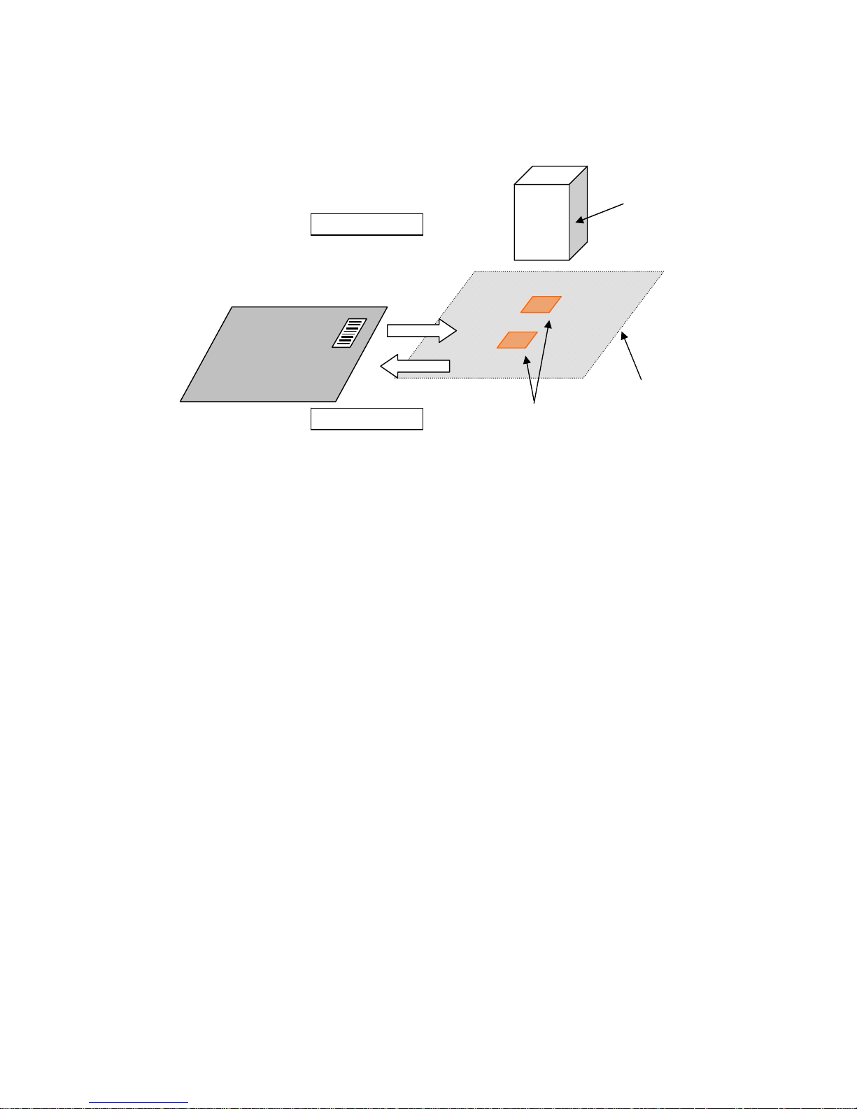
1.2 Product Description
View from rear
MAC xx:xx:xx:xx:xx
DIO connecto
r
MAC address
Interface cable
LAN connector
Product label
Diffused illumination
Diffused illumination
Membrane switch
Spot illumination
Rear panel
Camera lens
TFIR-31LAN
TFIR-31LAN-H
Spot illumination B
Spot illumination A
Spot illumination A
Pointer illumination
Page 14
- 12 -
1.2.1 Monitor LED
1.2.1.1 Function of monitor LED
Note: The function of monitor LED differs in automatic tuning mode for camera
settings. Please refer to section 5.5 for the detailed information.
1.2.2 Teach button
The Teach button is used for automatic tuning (Refer to section 5.5).
1.2.3 Read button
The Read button acts as a trigger for the reader. It is also used for automatic
tuning (Refer to section 5.5).
1.2.4 LAN connector
• LAN interface (LAN)
Send and receive data to/from host device. LAN cable is not included.
LAN indicator (Green): On when the LAN connection is established.
LAN indicator (Red): Blinking when data is being transferred.
LED Color Name Description
A Red Ready Turn on when the reader is ready to work
B Green Sync Turn on when the reader receives SYNC signal
C Green GO Turn on when the reader successfully reads symbol(s)
D Red NG Turn on when the reader fails to read symbol(s)
Detail of membrane switch
CB
A
Teach Read
D
Monitor LED × 4
Read buttonTeach button
LAN indicator (Green) LAN indicator (Red)
RJ-45(LAN) connector
Page 15
- 13 -
1.2.5 DIO connector
• 2 Digital Outputs: GO, NG
Three photo coupler isolated outputs are available.
“GO” and “NG” are used to signal the result of decode. These signals can also
be configured to be “Ready” and “Busy” by the serial command. Refer to section
7.13 General Operation for detailed information.
1.2.5.1 Detail of the GO & NG singnal
Signal name Description
GO signal GO signal is associated with Good Read, which is ON
during the specified time set by the GOOUT command
when the symbol is decoded successfully. And also this
signal is OFF when starting the next reading.
NG signal NG signal is associated with No Read, which is ON
during the specified time set by the NGOUT command
when the symbol is not decoded successfully. And also
this signal is OFF when starting the next reading.
Ready signal Ready signal is ON when the reader is ready for reading.
Busy #1 signal Busy #1 signal is ON while the reader is reading (except
switch chattering delay), and this signal will be OFF after
decoding.
Busy #2 signal Busy #2 signal is ON while the reader is reading (except
switch chattering delay), and this signal will be OFF after
transmission of the decoded data.
In the factory default settings the signals are as below:
GO Æ GO signal, NG Æ NG signal
When changing these parameters, save the settings to the internal flash
memory (using the WSETS command) and turn off the power and on it again.
Using the “Busy #2 signal”, make sure the settings of RSCS=1 and TCPCS=1.
• 1 Digital Input: SYNC
This signal is used to initiate reading.
(Sync signal can be sent by the serial command as well.)
Page 16
- 14 -
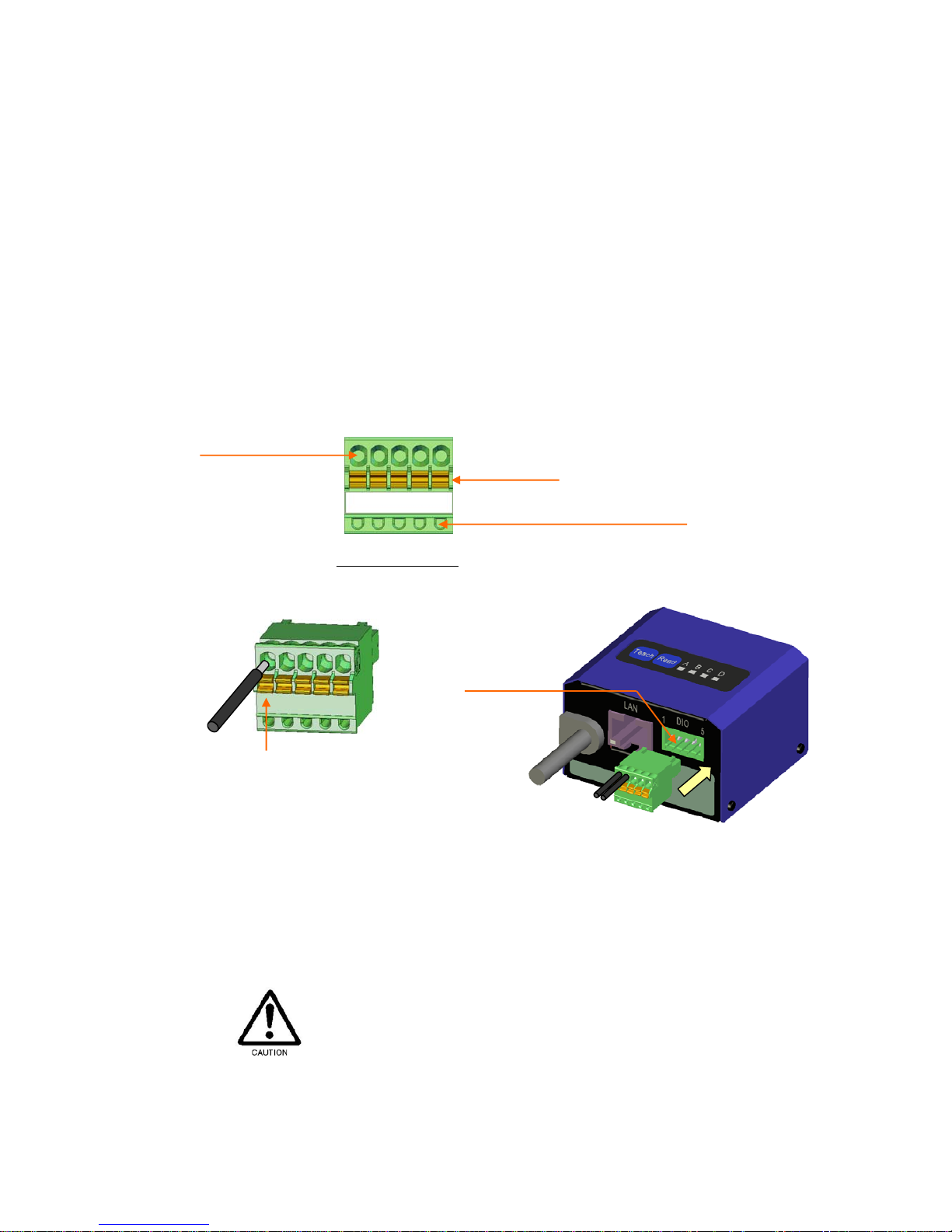
• DIO cable assembly
To interface with external equipment, use an accompanying DIO-plug
connector.
- Stripped off about 8mm in length of the outer jacket of a wire, and then use a
small screwdriver to hold down the small orange tab. After that, insert the
wire into the insertion opening next to the tab of the DIO-plug connector.
- The wire is locked when releasing the tab.
Note: The DIO-plug is attached to the DIO-socket (Factory default).
Applicable wire : AWG#20 to 26
Stripping length : 8mm
DIO connector socket : MC 0,5/ 5-G-2,5(PHOENIX CONTACT)
DIO connector plug : FK-MC 0,5/ 5-ST-2,5(PHOENIX CONTACT)
DO NOT unplug the DIO-plug by grasping the cable. It may cause breaking of wire.
1 2 3 4 5
Orange tab
Continuity check hole (Φ1mm)
Insertion opening
Detail of DIO-plug
Use a small screwdriver to hold down
the small orange tab while you insert the
wire into the insertion opening next to
the tab.
Plug the DIO-plug into the DIO-socket.
DIO-socket
Page 17

- 15 -
1.2.6 Interface cable
RS232C and power input for the reader.
• RS232C interface: RxD, TxD, CTS, RTS
Through RS232C, the reader sends the reading data and status to the host
computer. This interface also receives configuration commands from the host
device.
• DC power jack
5Vdc power is supplied from/through the optional AC adapter.
1.2.7 Internal illumination source
TFIR-31LAN-H
The spot type light source illuminates the central part of the image reader’s field
of view.
The diffused type light source illuminates the entire field of view.
TFIR-31LAN
The spot type-A light source illuminates the peripheral part of the field of view.
The spot type-B light source illuminates the central part of the field of view.
1.2.8 Camera lens
The reader captures images through the lens.
Page 18
- 16 -
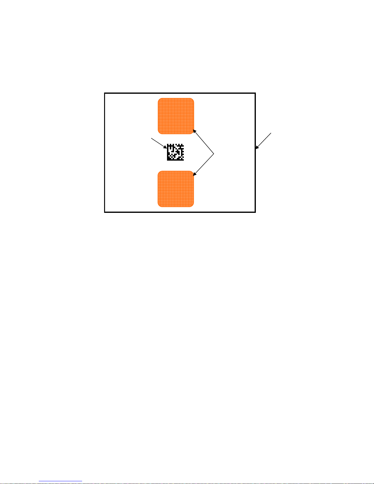
1.2.9 Camera and pointer illumination
Two pointer illuminations (aiming beam) indicate the central area of the image
reader’s field of view.
Symbol
Pointer
illumination
Field of view
Page 19
- 17 -
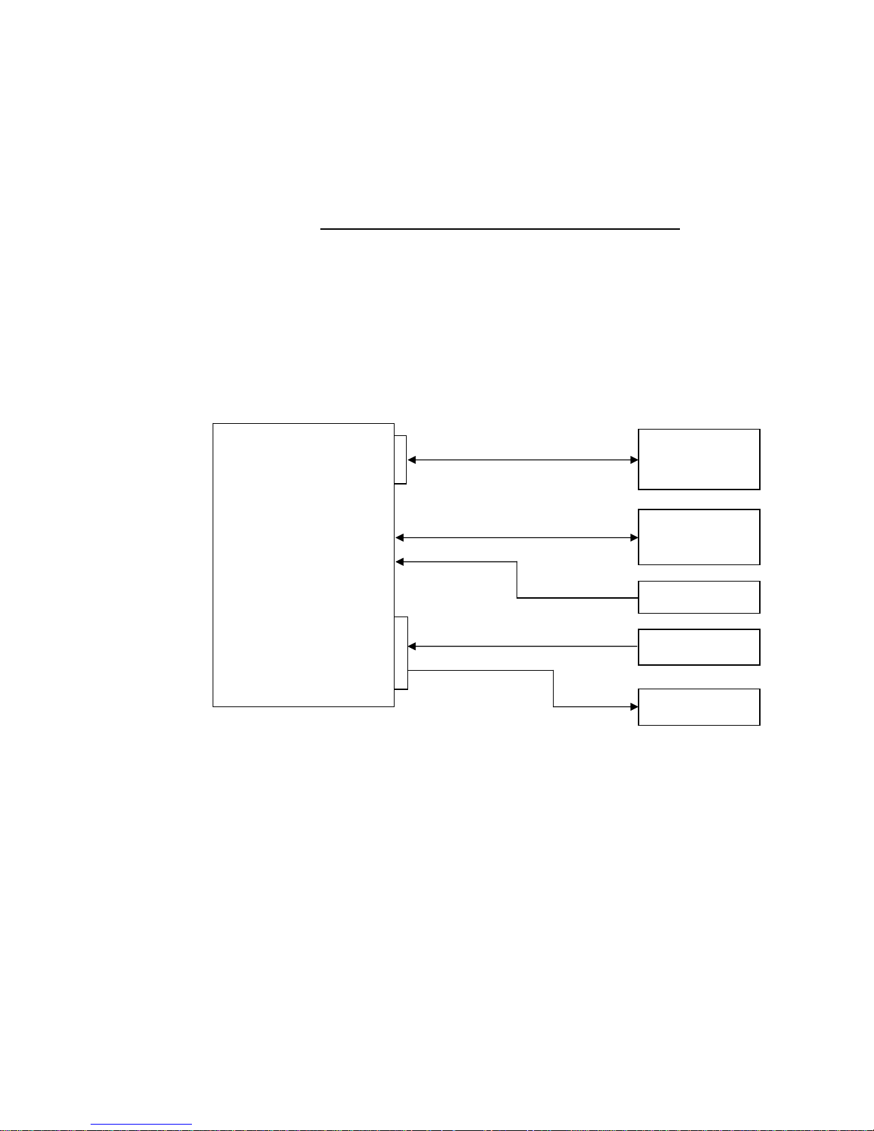
2 Configuration
2.1 Preparation
1- Establish communication between the reader and a host device. Please
refer to section 2.3 Communication port selection (RS232C, LAN)
for
detailed information.
2- Supply power from the interface cable to the reader. The LED-A (Ready)
turns on (red) if the reader is correctly powered. A combination of 2 long
beeps and 3 short beeps will indicate that the reader has started up
correctly.
< Block diagram of TFIR-31LAN’s connection >
Refer to section 9 for example configuration.
TFIR-31LAN
TFIR-31LAN-H
Interface cable
LAN
DIO
Digital input
RS232C
Ethernet
5Vdc
Digital output
AC adapter
Sensor
PLC
PLC
HUB
Host device
Host device
PLC
Page 20

- 18 -
2.2 Reading flow
1. Input a trigger signal that is one of 3 types below:
• Serial command
• Digital input (SYNC input)
• Press the Read button on the membrane switch
The LED-B (SYNC) turns on (green) and the reader start reading.
2. Result of reading
(1) Good Read
• 1 short beep
• Symbol’s data will be sent through the interface (RS232C, LAN).
• Digital output “GO” is ON.
• LED-C (GO) turns on (green).
Note: The activated period of “GO” and the monitor LED-C are configurable
through serial commands.
(2) No Read
• No beep
• Error code will be sent through the interface (RS232C, LAN).
• Digital output “NG” is ON.
• LED-D (NG) turns on (red).
Note: The activated period of “NG” and the monitor LED-D are configurable
through serial commands.
Page 21

- 19 -
2.3 Communication port selection (RS232C, LAN)
The communication port, which can be either RS232C and/or LAN as selected by the
“COMFROM” command, is used for the following purposes:
• Receive serial commands such as reading trigger (SYNC input)
• Send the result of reading.
RS232C interface is selected as default.
Note: With COMFROM=2, the reader needs to send data through both the RS232C and
LAN interfaces. If one or both of them do not receive data correctly, the reader will stop
sending data until the data on the interfaces is cleared. To avoid this situation, turn off
RSCS control (RSCS=0) or establish both connections correctly.
2.4 Configuration
TFIR-31LAN can be configured by sending the serial command through the
communication port selected.
2.5 Transfer image data
Using “TECT for TFIR-317x” software allows the download of images from the
reader. The image size is 752 x 480 pixels and is in BMP format.
The estimated transfer time through RS232C and LAN interfaces are as below:
RS232C : 60 seconds (Baud rate is 115.2Kbps)
LAN (10BASE-T) : Less than 1 second (varies due network conditions)
Command Description
COMFROM=0 Only RS232C (default)
COMFROM=1 Only LAN
COMFROM=2 RS232C and LAN *
Page 22

- 20 -
3 Operation Mode
TFIR-31LAN series image reader can operate in “Operational Mode” or “Diagnostic
Mode”.
Operational Mode Command Description
Single Reading Mode SYNCMODE=0
The reader performs a single read for
each SYNC input.
Reading Timeout Mode
SYNCMODE=1
The reader reads repeatedly for the
duration time, set by “TOTALLIM” after
the SYNC input, or reads until the
decoding is successful. “TOTALLIM” is
set through the serial commands (see
Chapter 4 for more details)
External Trigger Mode
SYNCMODE=2 The reader reads continuously while the
SYNC input is active.
Autosense Mode
SYMCMODE=3
The reader detects a symbol coming into
the field of view automatically and starts
reading it.
“Read” includes capturing and decoding an image.”
Diagnostic Mode Command Description
Normal Mode TEST=0
Use this command to return to Normal
Mode.
Test Mode TEST=1
Use this command to set the reader to
TEST mode. The SYNC signal will start
the test operation.
Continuous Reading Mode continue
Use this command to set the reader to
Continuous Reading Mode. To release
the reader from Continuous Reading
Mode, send a “stop” command.
Diagnostic Mode is used to configure the reader. Do not use the Diagnostic Mode in
normal operation.
Page 23
- 21 -
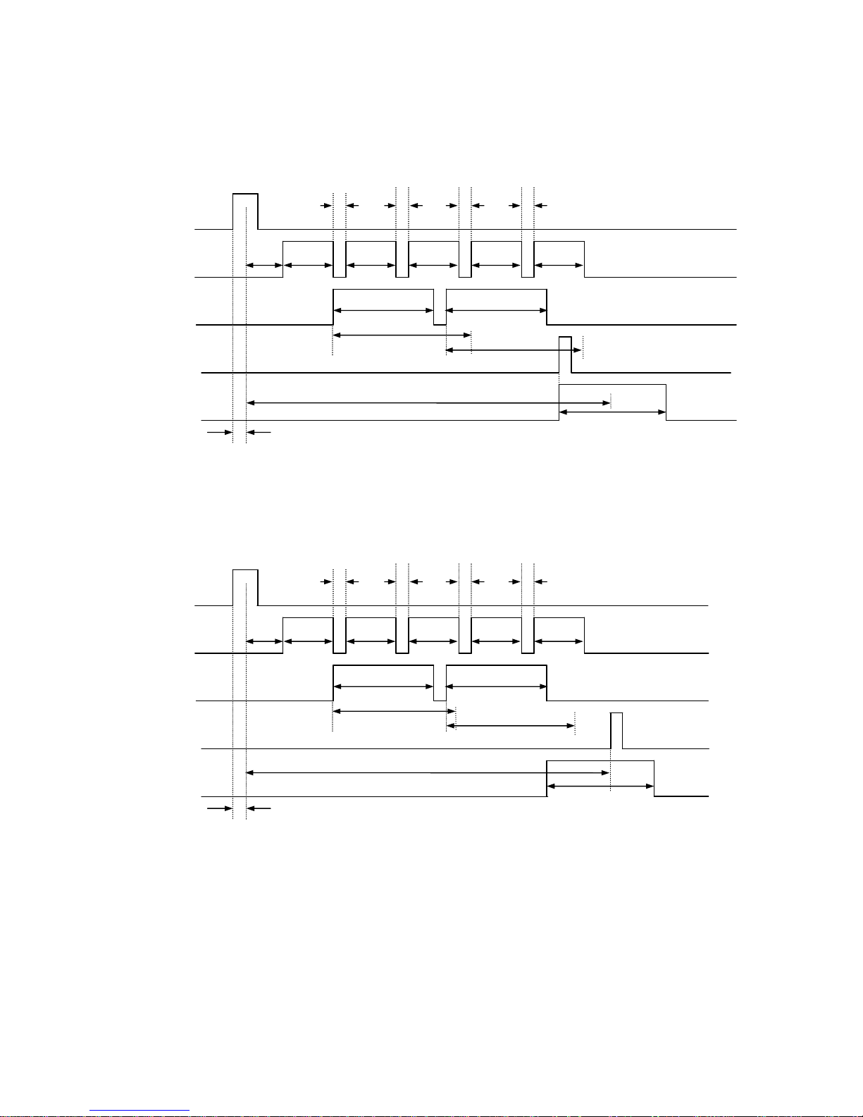
Timing Chart
DELAY: The time from SYNC ON to reading.
CHATT: The time needed for eliminating the chattering.
image: The time duration for capturing an image.
decode: The time duration for decoding.
DECODELIM: The maximum time limit for decoding.
GOOUT: The length of time the GO signal is asserted.
NGOUT: The length of time the NG signal is asserted.
SERIAL: The time the data is output through the serial interface.
MAXIMG: The maximum number of images in the buffer.
WAITIMG: The interval time between capturing images.
3.1 Single Reading Mode
The image reader performs a single read for each SYNC input.
3.1.1 Soft trigger, Good Read, Data transmission: After decode
DELAY
SYNC
IMAGE
DECODE
SERIAL
GOOUT
GOOUT
DECODELIM
decode1
image1
Page 24
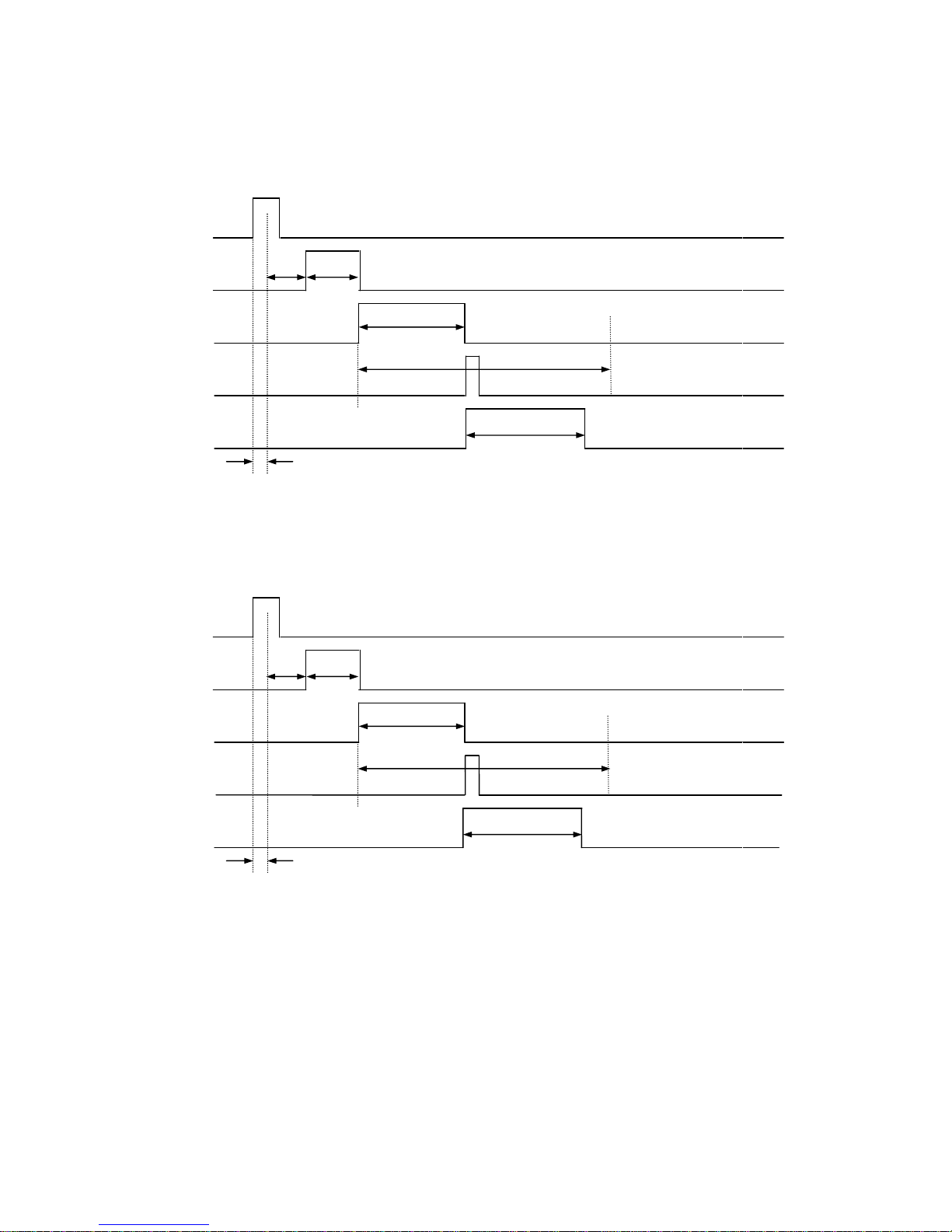
- 22 -
3.1.2 Hard trigger, Good Read, Data transmission: After decode
3.1.3 Hard trigger, No Read, Data transmission: After decode
DELAY
SYNC
IMAGE
DECODE
SERIAL
NGOUT
NGOUT
CHATT
DECODELIM
decode1
image1
DELAY
SYNC
IMAGE
DECODE
SERIAL
GOOUT
GOOUT
CHATT
DECODELIM
decode1
image1
Page 25
- 23 -
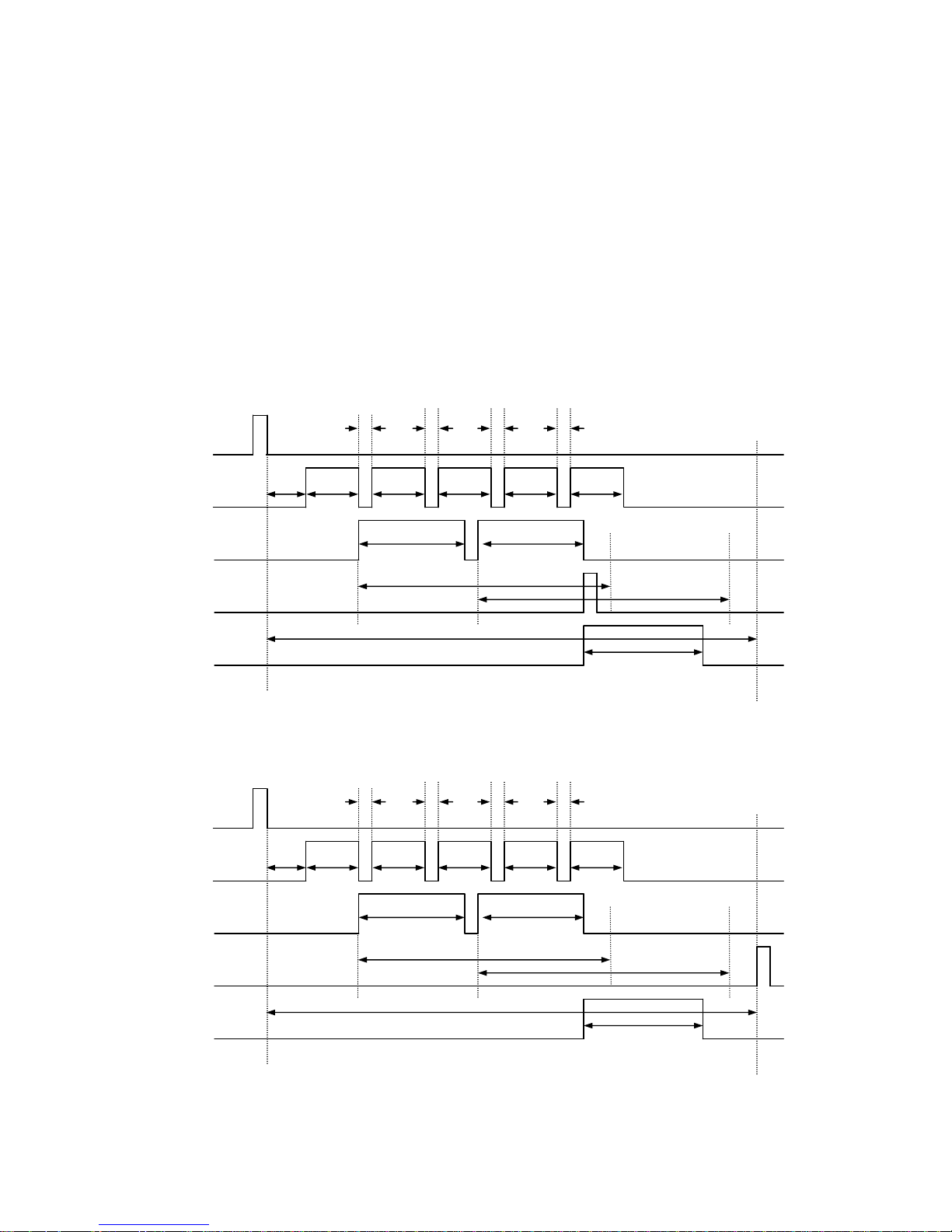
3.2 Reading Timeout Mode
The image reader reads the symbol repeatedly during the specified time, set by
“TOTALLIM” after the SYNC input, or reads until the decodeing is successful. If the
reader cannot decode successfully in the specified time, the reader will stop reading
and send the error code to the host.
Typically MAXIMG is set to a number greater than 1. The reader tries to decode the
image while capturing.
3.2.1 Soft trigger, Good Read, Data transmission: After decode
3.2.2 Soft trigger, Good Read, Data transmission: After SYNC OFF
DELAY
SYNC
IMAGE
DECODE
SERIAL
GOOUT
GOOUT
DECODELIM
DECODELIM
WAITIMG WAITIMG WAITIMG WAITIMG
decode1 decode2
image1 image2 image3 image4 image1
TOTALLIM
DELAY
SYNC
IMAGE
DECODE
SERIAL
GOOUT
GOOUT
DECODELIM
DECODELIM
WAITIMG WAITIMG WAITIMG WAITIMG
decode1 decode2
image1 image2 image3 image4 image1
TOTALLIM
Page 26
- 24 -
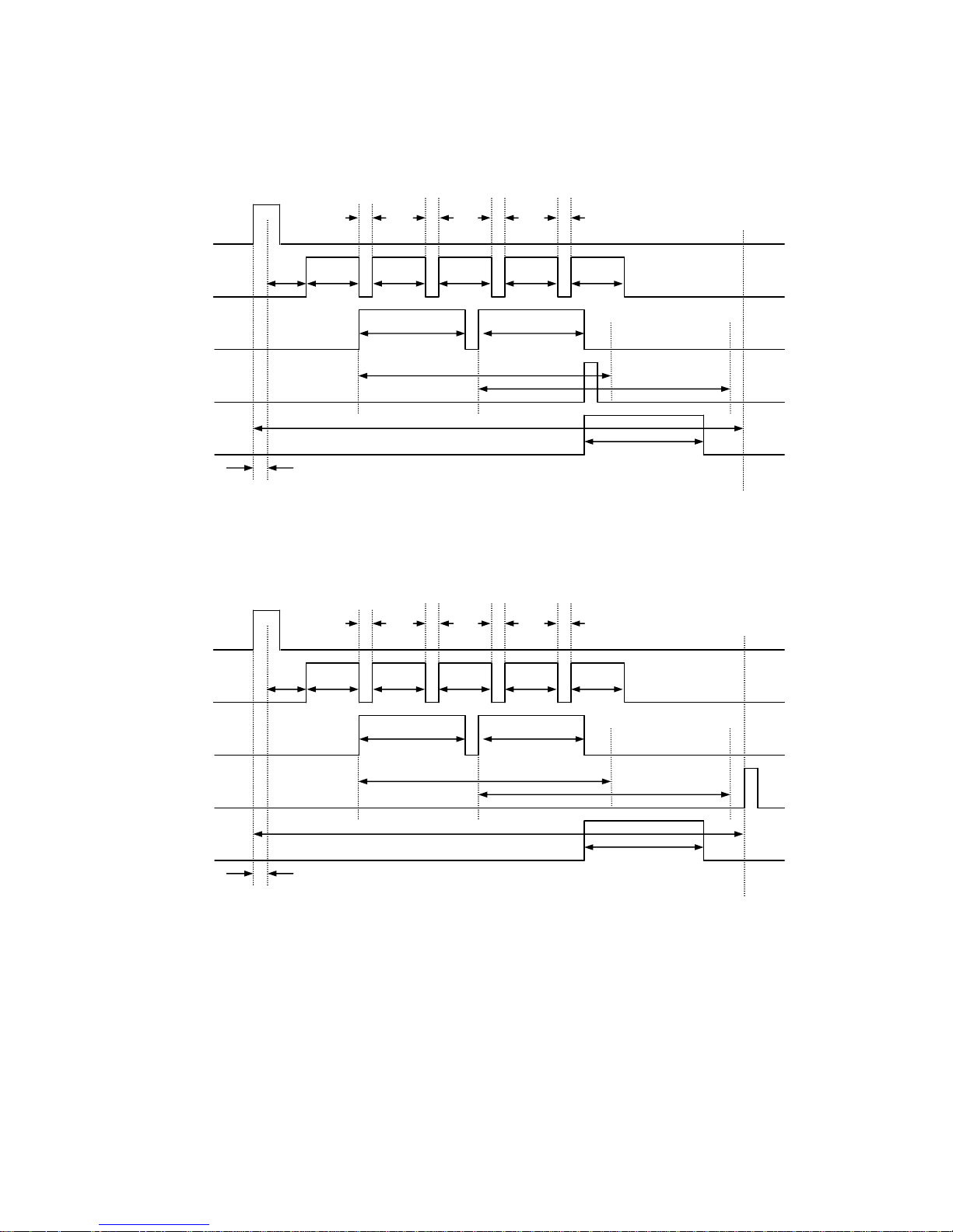
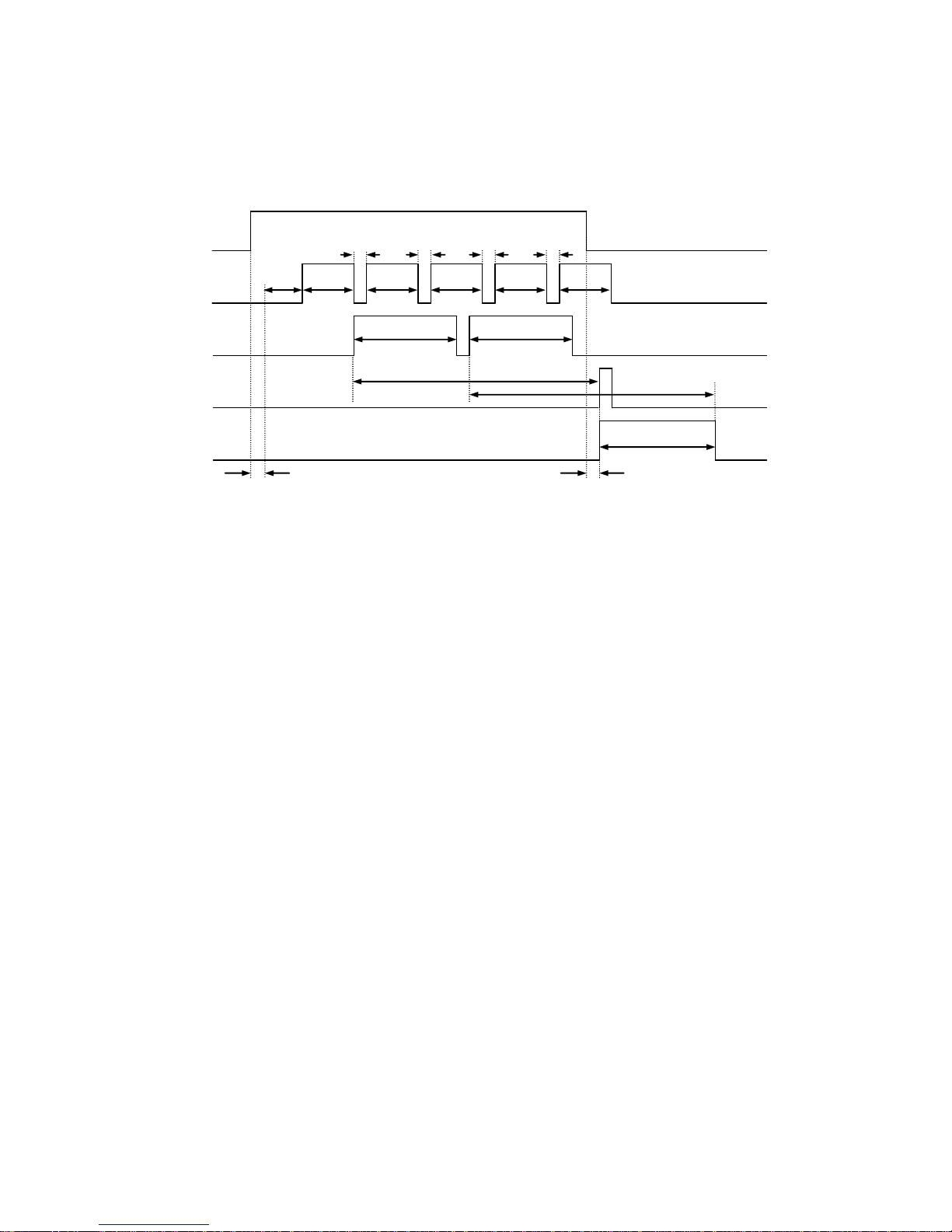
3.2.3 Hard trigger, Good Read, Data transmission: After decode
3.2.4 Hard trigger, Good Read, Data transmission: After SYNC OFF
DELAY
SYNC
IMAGE
DECODE
SERIAL
GOOUT
GOOUT
CHATT
DECODELIM
DECODELIM
WAITIMG WAITIMG WAITIMG WAITIMG
decode1 decode2
image1 image2 image3 image4 image1
TOTALLIM
DELAY
SYNC
IMAGE
DECODE
SERIAL
GOOUT
GOOUT
CHATT
DECODELIM
DECODELIM
WAITIMG WAITIMG WAITIMG WAITIMG
decode1 decode2
image1 image2 image3 image4 image1
TOTALLIM
Page 27
- 25 -
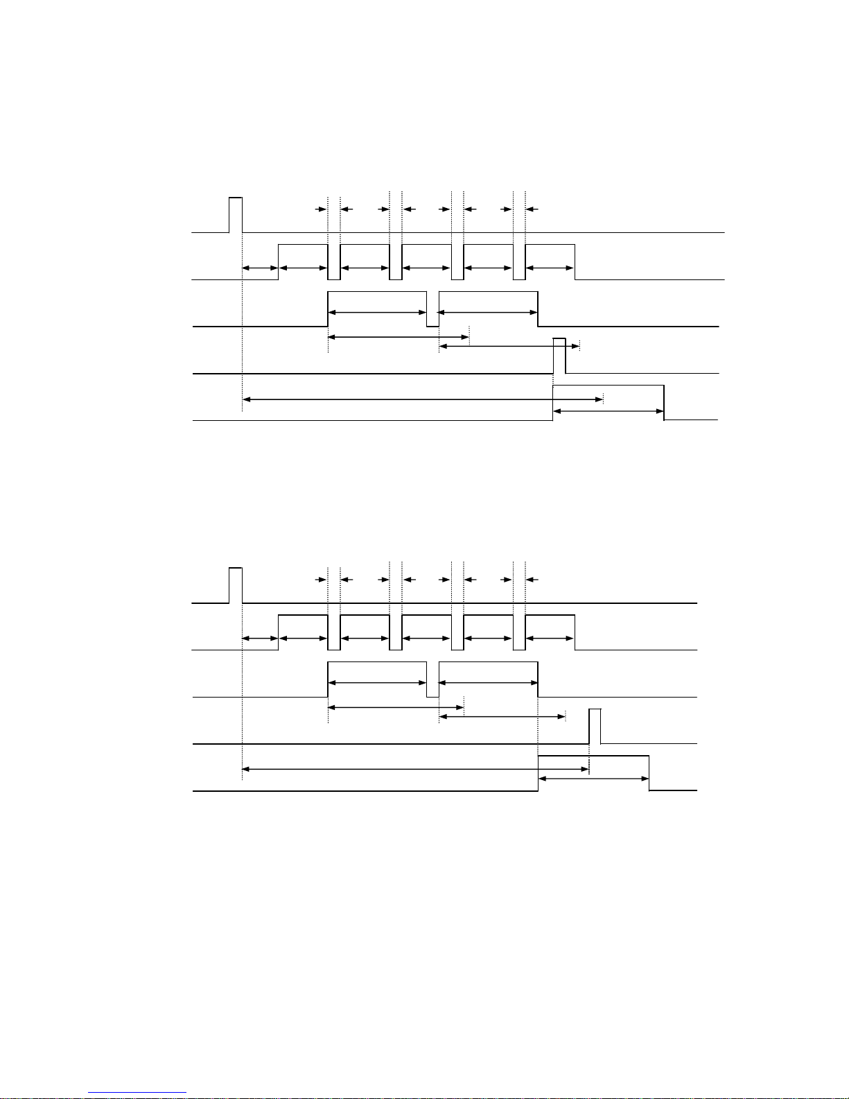
3.2.5 Soft trigger, No Read, Data transmission: After decode
3.2.6 Soft trigger, No Read, Data transmission: After SYNC OFF
SYNC
DELAY
IMAGE
WAITIMG WAITIMG WAITIMG WAITIMG
image1 image2 image3 image4 image1
DECODE
DECODELIM
DECODELIM
decode1 decode2
SERIAL
NGOUT
NGOUT
TOTALLIM
SYNC
WAITIMG WAITIMG WAITIMG WAITIMG
DELAY
IMAGE
image1 image2 image3 image4 image1
DECODE
DECODELIM
DECODELIM
decode1 decode2
NGOUT
NGOUT
TOTALLIM
SERIAL
Page 28
- 26 -
3.2.7 Hard trigger, No Read, Data transmission: After decode
3.2.8 Hard trigger, No Read, Data transmission: SYNC OFF
CHATT
DELAY
IMAGE
image1 image2 image3 image4 image1
SERIAL
SYNC
WAITIMG WAITIMG WAITIMG WAITIMG
DECODE
DECODELIM
DECODELIM
decode1
dcode2
NG-OUT
NGOUT
TOTALLIM
DELAY
SYNC
IMAGE
WAITIMG WAITIMG WAITIMG WAITIMG
image1 image2 image3 image4 image1
SERIAL
NG-OUT
NGOUT
CHATT
TOTALLIM
DECODE
DECODELIM
DECODELIM
decode1
dcode2
Page 29
- 27 -
3.3 External Trigger Mode
The image reader reads continuously while the SYNC input is active.
Typically MAXIMG is set to a number greater than 1. The reader tries to decode the
image while capturing.
3.3.1 Hard trigger, Good Read, Data transmission: After decode
3.3.2 Hard trigger, Good Read, Data transmission: After SYNC OFF
DELAY
SYNC
IMAGE
DECODE
SERIAL
GO-OUT
GOOUT
CHATT
DECODELIM
DECODELIM
WAITIMG WAITIMG WAITIMG WAITIMG
decode1 decode2
image1 image2 image3 image4 image1
CHATT
DELAY
SYNC
IMAGE
DECODE
SERIAL
GO-OUT
GOOUT
CHATT
DECODELIM
DECODELIM
WAITIMG WAITIMG WAITIMG WAITIMG
decode1 decode2
image1 image2 image3 image4 image1
CHATT
Page 30
- 28 -
3.3.3 Hard trigger, No Read, Data transmission: After decode or SYNC OFF
DELAY
SYNC
IMAGE
DECODE
SERIAL
NGOUT
NGOUT
CHATT
DECODELIM
DECODELIM
WAITIMG WAITIMG WAITIMG WAITIMG
decode1 decode2
image1 image2 image3 image4 Image1
Page 31

- 29 -
3.4 Continuous Reading Mode
In Continuos Reading Mode the reader read repeatedly. It is used for camera
adjustments.
To put the reader in Continuous Reading Mode, send the serial command “continue”
to the reader, and then send the serial command “g” to start reading.
To exit the Continuous Reading Mode, send the serial command “stop” to the reader.
3.5 Test Mode
In Test Mode the reader can measure the reading ratio. It is used for checking of the
reading condition and stability.
To put the reader in Test Mode and start reading, send the serial command
“TEST=1” to the reader.
To exit the Test Mode, send the serial command “TEST=0” to the reader.
With Test Mode, the reader will output an asterisk (*) to the host for each 10% of total
number of reading. The reader will stop the Test Mode after output an asterisk 10
times.
(Example output)
*** TEST MODE ***
1 2 3 4 5 6 7 8 9 10
* * * * * * * * * *
NG 1:OK 99/SYNC 100
NG 1.00%:OK 99.00%
(Output format)
NGaaaaa:OKbbbbb/SYNCccccc[CR]
NGddd.dd%:Okeee.ee%[CR]
aaaaa : NG Count (0 - 65535, maximum number is 65535)
bbbbb : OK Count (0 - 65535, maximum number is 65535)
ccccc : SYNC Input (NOT displayed more than 65535 )
ddd.dd: NG Rate (0.00-100.00,
Displayed to the second decimal place)
eee.ee: OK Rate (0.00-100.00,
Displayed to the second decimal place)
Page 32

- 30 -
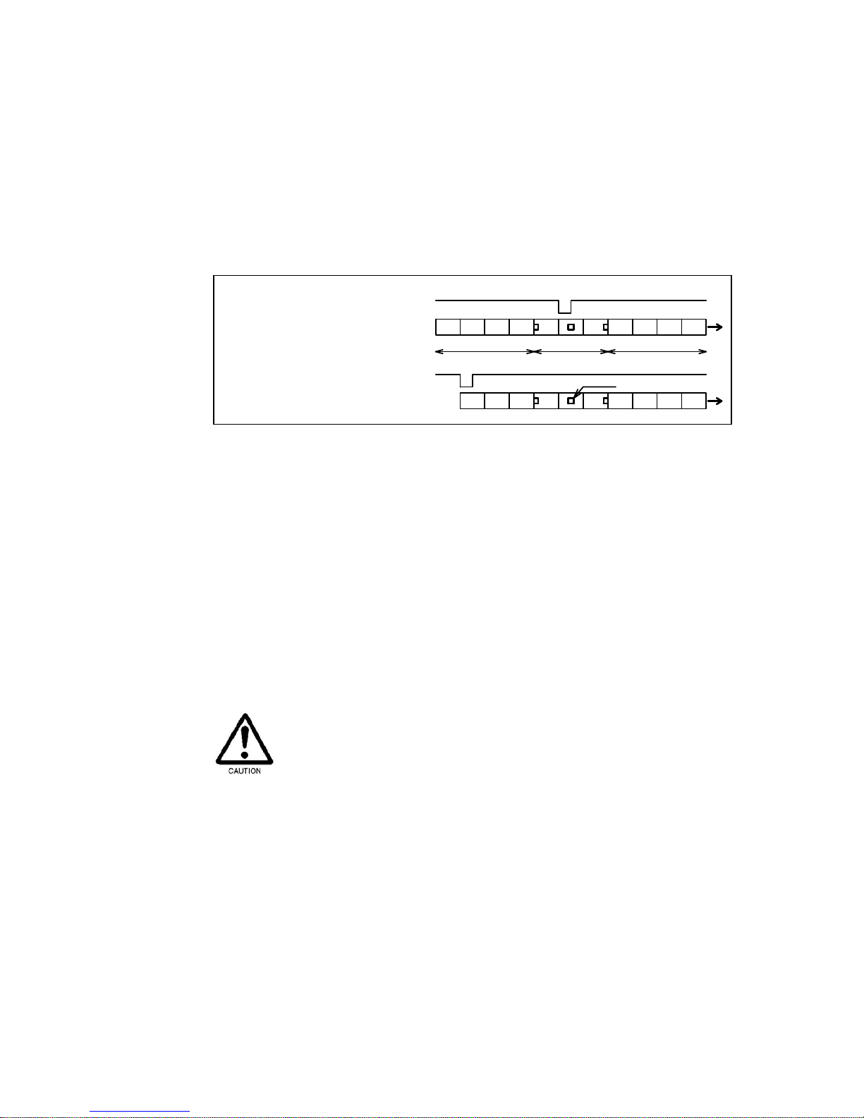
3.6 Cycle Buffer Function
In SYNCMODE=1 (Reading Timeout Mode) or SYNCMODE=2 (External Trigger
Mode), the Cycle Buffer Function is enabled when the MAXIMG number is greater
than 1 (default is 4). Set with the MAXIMG command. If the Cycle Buffer Function is
enabled, the reader captures multiple images after receiving the SYNC signal and
then stores the images to the buffer memory (up to 4 images). The reader starts
decoding from memory location #1, if it is not successful, the reader will attempt to
decode the image stored in memory location #2. The decoding is attempted during
the interval between capturing images. When the buffer memory reaches the final
location, the next image will be stored into buffer memory location #1 if the reader
has finished decoding that image. If the reader has not finished with that image, it will
wait until the decoding has finished.
1 2 3 4
WAITIMG WAITIMG WAITIMG
11
2
3
4
WAITIMG
1 2
WAITIMG
Decode
Capture
Pause Pause Pause
Check Check Check
Decoding for image #1 Decoding for image #2
Pause
Decoding for image #3 Decoding for image #4
Capture interval Capture interval Capture interval Capture interval Capture interval
Buffer memory
Page 33
- 31 -
How to use
Input the SYNC signal before the symbol comes into the reader’s field of view. If the
decoding is not successful, please adjust the timing of SYNC signal and the interval
(WAITIMG command).
SYNC signal
SYNC signal
Bofore FOV
FOV
After FOV
Symbol
Enable cycle buffer
Disable cycle buffer
3.7 Autosense Mode
In Autosense Mode the TFIR-31LAN can detect and decode symbols automatically.
The TFIR-31LAN detects changes in its field of view, such as changes of
environmental brightness or the motion of an object, the TFIR-31LAN begins
capturing images in an attempt to decode a symbol.
This function is suitable for reading a symbol printed on a document in the case of
inserting it in the field of view manually or reading a symbol without using of any
detection sensors.
With Autosense Mode, neither the trigger input through serial command nor digital
input affects on the reader. Other functions such as capturing an image, receiving a
Hex file and executing a Macro program, and putting the reader in Continuous
Reading Mode or Test Mode are disabled during Autosense Mode. Please turn
Autosense Mode OFF if any of the disabled function are needed.
Page 34
- 32 -
3.7.1 How to use
To put the TFIR-31LAN in Autosense Mode,
send the serial command "SYNCMODE=3" to the reader.
To exit the Autosense Mode,
send the serial command "SYNCMODE=0 (or 1 or 2) " to the reader.
#1 The reader waits for a symbol to come into the field of view.
#2 Place the symbol in the center between the two pointers.
#3 The reader detects the motion of an object in its field of view, it starts
reading the symbol on the object.
#4 In case of Good Read, the reader will send the decoded data and turn on
LED-C (green) and GO signal (digital output).
#5 In case of No Read, the reader will send the error code and turn on LED-D
(red) and NG signal (digital output).
#6 The reader is set in LFVERIFY=1 (double-read prevention), it will not send
decoded data and GO/NG status, and it will not increment the counter of
SYNC signal.
In order to read
Place the symbol in the center
between the two
p
ointers.
After reading
Remove the symbol from the
field of view
Field of view
TFIR-31LAN
Pointer
Page 35

- 33 -
#7 The reader will stop reading if it cannot decode successfully within the
decode timeout (default is 5 sec).
#8 After reading, remove the symbol from the field of view.
#9 When the reader detects the object goes out from the field of view, the
reader goes back to #1. It is the same when the reader detects absence of
the object within the detection ignored time (default is 0.5 second). In case
the object goes out while reading or is left in the field of view after reading,
the reader stops reading when the decode timeout is passed (#7).
3.7.2 In case the reader cannot read symbols in Autosense Mode.
Please remove the object from the field of view and wait until the pointer starts
blinking, and then place it in again (step #1 in section 3.7.1).
3.7.3 Serial command
Please refer to section 7.3 Symbol Reading
for the serial commands related to
Autosense Mode.
3.7.4 Enable/Disable Autosense Mode
Enable : SYNCMODE=3
Disable : SYNCMODE=0 or 1 or 2
3.7.5 Detection ignored time [LFMOVELIM]
In case the object remains at the position beyond the time limit after reading, the
reader will handle as the object goes out from the field of view and start next
reading.
If the time limit is set short, please remove the object from the field of view
immediately. If the reader takes long time to remove it due to large object size,
please set the time limit longer.
Page 36

- 34 -
3.7.6 Decode Timeout [TOTALLIM]
If the reader cannot decode a symbol successfully within the timeout, the reader
will stop decoding. In case the reader takes a long time to decode symbols which
contain a large amount of data, the timeout should be set longer. On the other
hand, in case the data amout is small, the timeout can be set short.
3.7.7 Sensitivity against brightness [VSENSE]
The value of the sensitivity should be set higher in case the reader tends to miss
the object coming into the field of view. On the other hand, the value should be set
lower in case the reader is highly sensitive to detect motion change of the object.
3.7.8 Double-read prevention [LFVERIFY]
When the reader reads the same symbol again within the specified time, the
second read will be ignored.
3.7.9 Double-read prevention time [LFVWAIT]
This setting is for LFVERIFY.
3.7.10 Illumination setting with Autosense Mode [LFLIGHT]
The reader flashes the internal illumination in Autosense Mode if this setting is
enabled.
3.7.11 Output the status of Autosense Mode
?LF[CR] : Output the status of Autosense Mode
(Example of output)
******** STATUS ******** TFIR-31LAN
LFMOVELIM=2 (0:100ms 1:300ms 2:500ms 3:1000ms
4:1500ms 5:2000ms 6:2500ms 7:3000ms)
LFVERIFY=1 (0:OFF 1:ON) LFVWAIT=6 (x500ms 1-40)
LFLIGHT=1(0:OFF 1:ON)
VSENS=2 (0-4)
********* END ********** TFIR-31LAN
System version = M21C-V1.0a
Decode version = M21A-V1.0a
Page 37

- 35 -
Note: TOTALLIM can be checked in the status of ?4.
?4
******** STATUS ******** TFIR-31LAN
MODE=0 0:normal 1:image-out
3:OK,NG 4:OK 5:NG
SYNCMODE=1 0:normal 1:time out 2:hard trig
TEST=0 (0:normal 1:test mode)
TMN=10 TEST=1;n-times(10-1000)
DECODELIM=500 100-10000 step10
TOTALLIM=5000 100-30000
DTTX=0 0:non 1:add(****ms)
[ … ]
POINTER=1 (0:OFF 1:ON)
********* END ********** TFIR-31LAN
System version = M21C-V1.0a
Decode version = M21A-V1.0a
Page 38

- 36 -
4 Configuration for symbol reading
4.1 Configuration parameters
The following parameters are set to get decodable images:
(1) Decode area [DDMwindow]
(2) Illumination control [DDMlight]
(3) Internal illumination [DDMled]
(4) Illumination intensity [DDMbrightness]
(5) Shutter speed [DDMshutt]
(6) Extra gain value [DDMexgain]
(7) Black level adjustment [DDMblack]
(8) Image preprocessing [DDMpreproc]
(9) Mirrored symbol [DDMmirror]
4.1.1 Decode area
(1) Decode area [DDMwindow]
Decode area is used to specify the the area of the image to be decoded
(Shown below). Smaller decode area can lead to a faster decoding speed, but
smaller areas may make it difficult to position the symbol within the smaller
decode area.
Horizontal: 100% (752) 75% (564) 50% (376) 25% (188)
Vertical: 100% (480) 75% (360) 50% (240) 25% (120)
DDMwindow=a,b (a, b=0,1,2,3 0:100%,1:75%,2:50%,3:25%)
a: for Horizontal, b: for Vertical
Generally, a smaller reading area will lead to a shorter decode time. However if
the reading area is too small, the reading ratio could be decreased due to the
smaller margin between code size and the decoding window size.
Sketch of decode area
100%
75%
50%
25%
Page 39

- 37 -
4.1.2 Illumination
(2) Illumination control [DDMlight]
DDMlight=a (a: 2,3)
2: Turn Internal illumination OFF when capturing an image.
3: Turn Internal illumination ON (with pulsed operation) when capturing
an image.
(3) Internal illumination source [DDMled]
DDMled=c,b (c,b: 0,1)
TFIR-31LAN-H
c 0: Disable spot illumination
1: Enable spot illumination
b 0: Disable diffused illumination
1: Enable diffused illumination
TFIR-31LAN
c 0: Disable spot illumination B
1: Enable spot illumination B
b 0: Disable spot illumination A
1: Enable spot illumination A
(4) Illumination Intensity [DDMbrightness]
DDMbrightness=a (a: 0 to 50)
Adjust the illumination intensity from 0 to 50 (0: Off to 50: Brightest).
4.1.3 Shutter speed
(5) Shutter speed [DDMshutt]
Configure the shutter speed of the reader’s camera module. This parameter
affects the brightness of the images taken by the reader. To make the image
brighter, the shutter speed can be lowered, but low shutter speeds may
introduce motion blur into the image.
DDMshutt=a (a: 0 to 8)
0: 1/60 (second),
1: 1/125,
2: 1/250,
3: 1/500,
4: 1/1000,
5: 1/2000,
6: 1/4000,
7: 1/6000,
8: 1/8000
Page 40

- 38 -
4.1.4 Extra gain value
(6) Extra gain value [DDMexgain]
Extra gain value also affects the brightness of the images taken by the reader.
While a higher extra gain value will brighten the image, it could also introduce
noise at the higher settings.
DDMexgain = a (a: 1 to 15)
4.1.5 Black level adjustment
(7) Black level adjustment [DDMblack]
The
black level can improve the contrast of the images taken by the reader
by controlling the black level of the CMOS sensor. Better contrast can lead to a
higher reading ratio. However higher black level will make the image too dark
for optimal decoding.
DDMblack=a (a: -127 to 127)
4.1.6 Image preprocessing
(8) Image preprocessing [DDMpreproc]
Image processing filters are available for difficult to decode symbols. Under
certain circumstances enlarging, black/white reversal, or applying contrast
enhancement will increase the decodability of the images captured. Please
refer to section 7.8 Image Preprocessing
for more imformation.
4.1.7 Mirrored symbol
(9) Mirrored symbol [DDMmirror]
The reader can decode symbols that are mirrored by settings the DDMmirror
command appropriately.
DDMmirror=a (a: 0 to 3)
0: Read only normal type (not mirrored)
1: Read only mirrored type
2: Read normal type and if it fails, try to read it as mirrored type
3: Read mirrored type and if it fails, try to read it as normal type
Page 41

- 39 -
4.2 Camera Control Mode
The TFIR-31LAN series image reader can store multiple settings in TABLE. The
TABLE consists of 9 tables (#0 to #8). In “AGC=D” (Fixed Gain Mode) and
“AGC=E” (Automatic Gain Control Mode), the reader uses Table #0. In “AGC=T”
(Table Mode), the reader uses Table #1 to #“n”. The “n” can be configured by
ENABLEDDMTBL=n command.
■Fixed Gain Mode [AGC=D]
In Fixed Gain Mode, the reader uses only Table #0 settings. The settings in
Table #0 will not be changed automatically.
■Automatic Gain control mode [AGC=E]
In Automatic Gain Control Mode, the reader uses only Table #0 settings and
gain value in Table #0 will be changed automatically through instructions
from decoder. This mode is useful especially for symbols printed on paper.
This mode is effective in Reading Timeout Mode or External Trigger Mode.
Fixed gain: D
Table #0
Table #1
Table #2
Table #3
Table #4
Table #5
Table #6
Table #7
Table #8
Automatic gain: E
Table: T
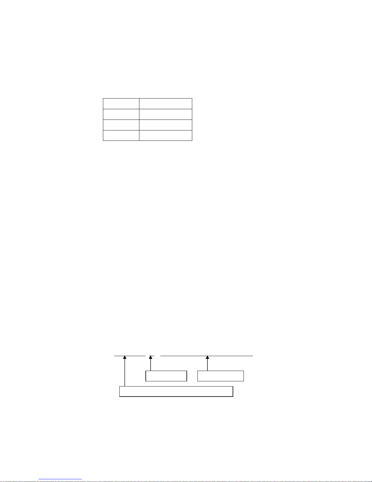
Camera Control Mode TABLE
Page 42

- 40 -
■Table Mode [AGC=T] (Default)
In Table Mode, the reader uses the settings stored in tables. There are eight
tables available, numbered from #1 to #8. The ENABLEDDMTBL command
determines the number of tables to be used when the reader is attempting to
decode a symbol.
This mode is most effective for still objects. To use this mode, select Reading
Timeout Mode or External Trigger Mode.
Page 43

- 41 -
4.3 Detail of Table Mode
Up to 8 tables can be used while the trigger is activated.
ENABLEDDMTBL=a (a: 1 to 8)
e.g.1) Use 3 tables (a=3)
Table #1, #2 and #3 are enabled and Table #4 through #8 will not be used. If
the reader successfully decodes a symbol with Table #1, Table #1 will be used
in the next reading.
If the reader failed to decode a symbol with Table #1, the settings will switch to
Table #2, etc.
If the reader failed to decode with Table #3, the settings will switch back to
Table #1.
e.g.2) Use 1 table (a=1)
Only Table #1 is enabled. Table #2 through #8 will not be used. As the result,
Table #1 is always used every reading.
The
following shows the structure of the Table. Each table has 9 types of
parameters:
(1) Decode area [DDMwindow]
(2) Illumination control [DDMlight]
(3) Internal illumination [DDMled]
(4) Illumination intensity [DDMbrightness]
(5) Shutter speed [DDMshutt]
(6) Extra gain value [DDMexgain]
(7) Black level adjustment [DDMblack]
(8) Image preprocessing [DDMpreproc]
(9) Mirrored symbol [DDMmirror]
Table #0 (1) (2) (3) (4) (5) (6) (7) (8) (9)
Table #1 (1) (2) (3) (4) (5) (6) (7) (8) (9)
Table #2 (1) (2) (3) (4) (5) (6) (7) (8) (9)
Table #3 (1) (2) (3) (4) (5) (6) (7) (8) (9)
Table #4 (1) (2) (3) (4) (5) (6) (7) (8) (9)
Table #5 (1) (2) (3) (4) (5) (6) (7) (8) (9)
Table #6 (1) (2) (3) (4) (5) (6) (7) (8) (9)
Table #7 (1) (2) (3) (4) (5) (6) (7) (8) (9)
Table #8 (1) (2) (3) (4) (5) (6) (7) (8) (9)
Page 44

- 42 -
The following flow chart shows the procedure of Table Mode operation:
< Flow chart of Table mode >
4.3.1 Edit table
1. Set the target Table #.
Send the serial command below to assign the table number to be edited.
EDITDDMTBL=a (a: 1 to 8)
2. Configure the parameters.
Refer to section 4.1 Configuration parameters
for detailed information.
3. Edit another table
Repeat the step 1 & 2.
Read OK?
Yes
Yes
No
Trigger
Use this Table
Increment table number
Read OK?
No
Use the first table in the next reading
Use the next table
Page 45

- 43 -
5 Advanced Functions
5.1 Preset Mode
TFIR-31LAN series image reader has the function of Preset Mode that is used for
verification. The reader compares the decoded data with the preset data (Registered
data) and will output only if the data is matched (It does not compared the type of
symbol).
If the Preset data is “ABCDEFG”, the reader will output the data of Symbol A and B.
e.g.)
Data Symbol type
Symbol A ABCDEFG Data Matrix
Symbol B ABCDEFG Code39
Symbol C ABCDEFGH Data Matrix
This function has two modes, Preset Mode 1 and Preset Mode 2.
PREM=0[CR](*) : Preset Mode 0 (Preset Mode is disabled)
PREM=1[CR] : Preset Mode 1 (Preset data is the first decoded one after power up)
PREM=2[CR] : Preset Mode 2 (Preset data is registered in advance)
To disable Preset Mode, send the command “PREM=0”.
5.1.1 Preset Mode 1
In this mode, the preset data is the first decoded data after power up.
Data comparison is only successful when the code matches completely.
The preset data must be set as every time the reader is powered on because
the data is not saved to internal flash memory.
Setup procedure of Preset Mode 1
1. Send the following commands
PREM=1[CR]
WSETS[CR] : Save the settings to internal flash memory.
2. Power-on reset
3. Read the symbol that contains the data to be used as the preset data.
Page 46

- 44 -
5.1.2 Preset Mode 2
In this mode, the preset data is configured by the serial command. Data
comparison is completed by both complete and partial matching. It is possible to
save the preset data to internal flash memory.
Send the following command to set this mode:
PREM=2[CR]
SET=PREDabcd[CR] : Set the preset data (data is “abcd”)
SET=PRENa[CR] : Set the number of digits (a: 0 to 100)
WSETS[CR] : Save the settings to internal flash memory
e.g.1) Example 1: Only ”12345” is valid
12345 : match
1234 : mismatch
123456 : mismatch
012345 : mismatch
PREM=2[CR]
SET=PRED12345[CR] : Set the preset data (data is “12345”)
SET=PREN5[CR] : Set the number of digits (5 digits)
WSETS[CR] : Save the settings to internal flash memory
e.g.2) Example 2: Valid when first 4 digits are “ABCD”.
ABCD : match
ABCD333 : match
ABCD
777777 : match
ABC : mismatch
DABC333 : mismatch
77ABCD77777 : mismatch
PREM=2[CR]
SET=PREDABCD[CR] : Set the preset data (data is “ABCD”)
SET=PREN0[CR] : Set the number of digits (no count)
WSETS[CR] : Save the settings to internal flash memory
Page 47

- 45 -
e.g.3) Example 3: Valid when the length is 10 digits and the data from 3rd-digits
to 6th-digits are “ALFA”.
00ALFA1234 : match
AAALFAAAAA : match
00ALFA12345 : mismatch
0ALFA12345 : mismatch
PREM=2[CR]
SET=PRED??ALFA????[CR] : Set the preset data (data is “??ALFA????” and “?” is
mask.)
SET=PREN10[CR] : Set the number of digits (10 digits)
WSETS[CR] : Save the settings to internal flash memory
Page 48

- 46 -
5.1.3 Output the status of Preset Mode
?pre[CR] : Output the preset status
(Example output)
PREM=0 (0:non 1:power on 2:saved)
PRESET LENGTH:13
DATA(HEX):
34 39 3F 3F 3F 3F 3F 3F 3F 3F
3F 3F 3F
DATA(ASCII):
49???????????
(Output format)
PREM=a (0:non 1:power on 2:saved)[CR]
PRESET LENGTH:b[CR]
DATA(HEX):[CR]
XX XX XX XX XX XX XX XX XX XX[CR]
XX XX XX XX XX XX XX XX XX XX[CR]
XX XX XX XX [CR]
DATA(ASCII):[CR]
xxxxxxxxxxxxxxxxxxxxxxxx
a : Preset Mode
b : The digit of the length of the preset data
XX XX … : Preset data character (in hex)
xxxxxx… : Preset data character (in ASCII/JIS)
If the preset data include control code, it is transferred to “*”.
Page 49

- 47 -
5.2 Output additional information
5.2.1 ID Number
Add the ID Number (4 digits) at the beginning of the decoded data. It can be
used for multi-configuration with the reader. Host computer can recognize the
data which reader has sent. The ID is set by the serial command “BTID=xxxx”.
“xxxx” is the ID Number. To disable this function, send the command
“BTID=0000” to the reader.
5.2.2 Warning Information
Add the Warning Information for monitoring the decode condition at the
beginning of the reading data. This setting is enabled by sending the serial
command “CHKBCR=a,b”. “a” is for RS232C interface and “b” is for LAN
interface.
e.g.1)
CHKBCR=0,1 : Added only for RS232C.
CHKBCR=1,1 : Added for both interface.
CHKBCR=1 : Same as “CHKBCR=1,1”.
CHKBCR=0 : Same as “CHKBCR=0,0” (Disable).
Output format: (CcccEeeeDddd)
ccc: Contrast Information for the captured image
eee: Unused Error Correction rate
ddd: Decodability margin
e.g.2) Good Read
Data output: (C082D091E100)A123456A
Calculate contrast value of a symbol including quiet zone. The decoder
determines a rectangular area for the symbol and calculates the contrast
value from its brightness level. If there are multiple symbols, the calculated
value is for the first decoded symbol.
e.g.3) No Read
Data output: (C000E000D000)BR
Page 50

- 48 -
“000” is added in case of No Read.
5.2.3 Symbol Type Information
By enabling this setting (SYMBOLTX=1), the reader can add the Symbol Type
Information (symbol identifier) at the beginning of the decoded data. It is not
added in case of No Read.
5.2.4 Decode time
By enabling this setting (DTTX=1), the reader can add decode time at the end of
decoded data.
5.2.5 Total time and number of images captured after trigger input
Add number of images captured after trigger input and Total time from trigger
input to serial data output. It is not added in case of No Read.
Output format: (aa, bbbbbms)
aa: Number of images, bbbbb: Total time [ms]
5.2.6 Contrast Information
Add the Contrast Information of the last decoded image.
1. Good Read
Calculate contrast value of a symbol including quiet zone. The decoder
determines a rectangular area for the symbol and calculates the contrast
value from its brightness level.
If there are multiple symbols, the calculated value is for the first decoded
symbol.
2. No Read
Calculate contrast value for the whole image.
Symbol Type Symbol Identifier Symbol Type Symbol Identifier
Code39 ]A0 Data Matrix ]d1
Code128 ]C0 Maxi Code ]U1
EAN128 ]C1 PDF417 ]L0
Codabar ]F0 QR Code ]Q1
ITF ]I0 Composite ]e0
UPC/EAN/JAN none Customer code none
RSS ]e0 Aztec Code [z3
Code93 ]G0
Page 51

- 49 -
Output format: (aaa, bbb, ccc) 13 bytes
aaa : Maximum value of reflectance (000 to 255)
bbb : Minimum value of reflectance (000 to 255)
ccc : Contrast [%] =100 x (aaa - bbb) / 255 (000 to 100)
5.2.7 Quality Information (Unused Error Correction)
The percentage of the Unused Error Correction codeword of the 2D code is
added to the decoded data.
For example, if the decoder does not use any error correction, this value would
be 100. If the symbol is not decodable, the Quality Information will not be added.
Output format: (QT: ddd) 8 bytes
ddd: Quality (000 to 100)
5.2.8 Symbol Coordinates
The positional data of the symbol in the image is output along with the decoded
data. There are three types of outputs; Barycentric coordinates, Rectangular
coordinates and Barycentric / Rectangular coordinates.
(1) Barycentric coordinates
The origin (000, 000) of the barycentric coordinates is the center of the
field of view.
(Example output)
100000000990703(-122,+024)
Output format: Header + Data + (abbb,accc) + Terminator
a : + or b : x (0 to 999)
c : y (0 to 999)
Page 52
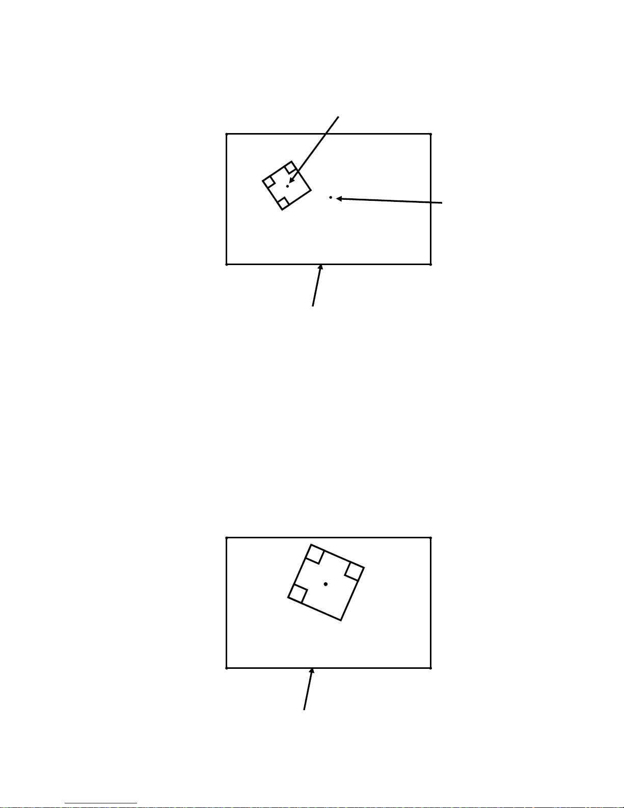
- 50 -
(2) Rectangular coordinates
The origin (000, 000) is the left-top edge of the field of view.
(Example output)
100000000990703(+269,+011)(+455,+086)(+386,+270)(+198,+199)
Output format: Header + Data + (A1) + (A2) + (A3) + (A4) + Terminator
A1 – A4 : (abbb,accc)
a : + or b : x (0 to 999)
c : y (0 to 999)
Barycentric coordinates
(-376,+239) (+375,+239)
(-376,-240) (+375,-240)
Origin
(+000,+000)
Field of view
Origin for rectangular coordinates
(+000,+000) (+751,+000)
(+000,+479) (+751,+479)
A2(+455,+086)
A1(+269,+011)
A3(+386,+270)
A4(+198,+199)
Field of view
Page 53
- 51 -
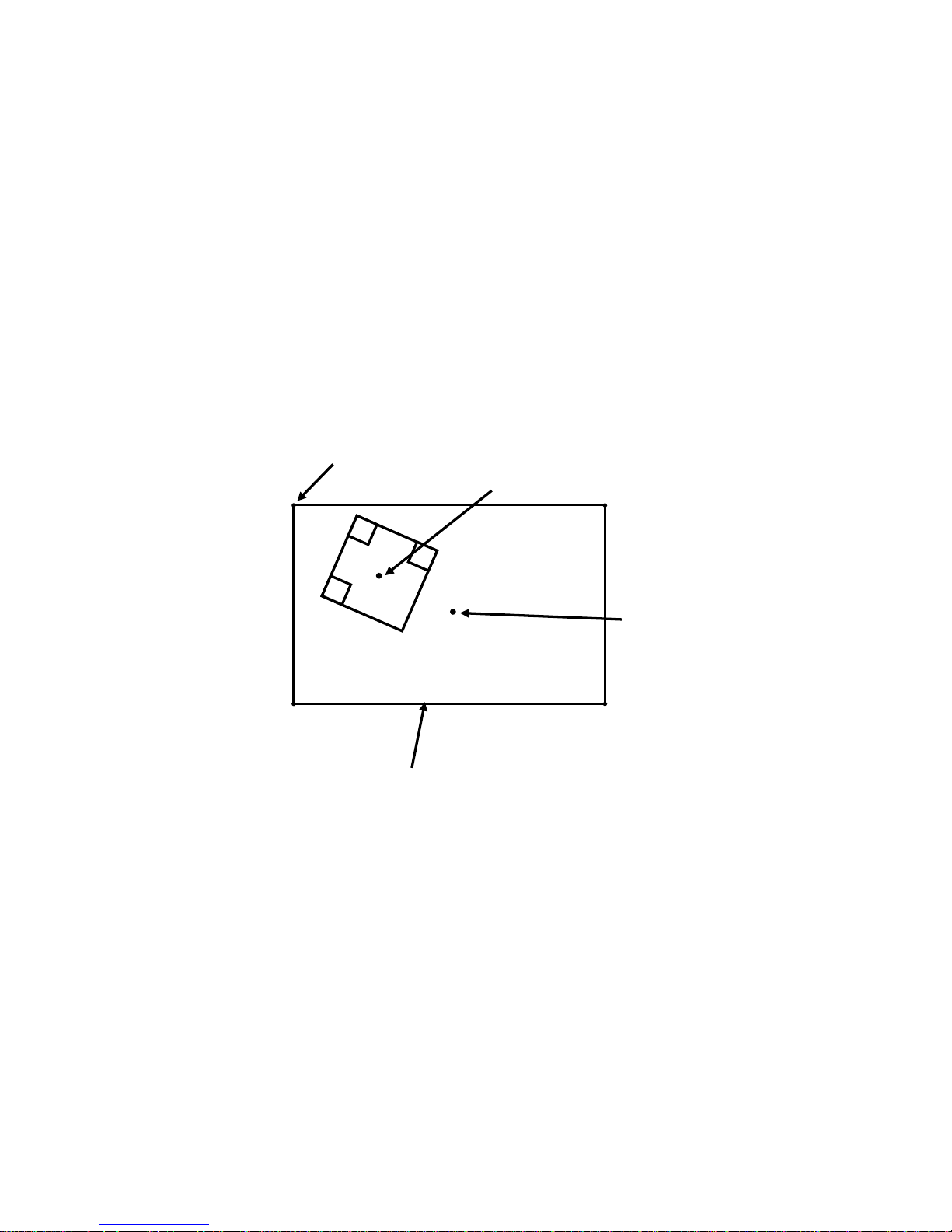
(3) Barycentric / Rectangular coordinates
(Example output)
100000000990703(+007,+103)(+269,+011)(+455,+086)(+386,+270)(+1
98,+199)
Output format: Header + Data + B + (A1) + (A2) + (A3) + (A4) + Terminator
B : The center of a symbol
B, A1 – A4 : (abbb,accc)
a : + or b : x (0 to 999)
c : y (0 to 999)
5.2.9 Table Number
(Example output)
100000000990703(ddmtbl=3)
Output format: Header + Data + (ddmtbl=a) + Terminator
a: Table Number
Field of view
The origin for rectangular coordinates
A2
A1
A3
A4
The origin for barycentric
coordinates
Barycentric coordinates
Page 54

- 52 -
5.3 Save Image
Up to 4 images can be stored to internal memory (Buffer #1 to #4).
The images need to be transferred to a host before turing off the power to the reader.
The images will be deleted from the internal memory when turning the power off.
Select type of image to be saved as follows:
- Image of Good Read
- Image of No Read
- Captured image (Raw image)
- Decoded image (Using the function of image preprocessing.)
Default settings:
IMGSAVE=1[CR] (*) : Save image of No Read.
IMGSEL=1[CR] (*) : Save preprocessed image when this function is enabled.
IMGFULL=1[CR] (*) : After images are stored in buffer from #1 through #4, latest
images will be overwritten in buffer #4.
To delete the image, send the “IMGCLEAR” command to the reader.
5.3.1 Select type of save image
Select type of image to be saved as follows:
IMGSAVE=0[CR] :
Disable this function
IMGSAVE=1[CR] (*) :
Save image of No Read
IMGSAVE=2[CR] :
Save image of Good Read
IMGSAVE=3[CR] :
Save image of Good Read and No Read
5.3.2 Save preprocessed image
IMGSEL=0[CR] : Save captured image (Raw image)
IMGSEL=1[CR] (*) : Save decoded image
In case of “IMGSEL=1”, the flame number used in cycle buffer memory need to be
identified.
OKFRAME=0[CR] (*) : Decoded image
OKFRAME=1 to 4[CR] : The image stored in the specified memory in
case of Good Read.
Page 55

- 53 -
NGFRAME=0[CR] (*) : The last image attempted to decode when No
Read.
NGFRAME=1 to 4[CR] : The image stored in the specified memory in
case of No Read.
5.3.3 Overwrite save
If the number of saved images is more than 4, latest image is stored in buffer #4 or
other #.
IMGFULL=0[CR] : Stored to internal buffer from #1 to #4 in order.
IMGFULL=1[CR] (*) :
After images are stored in buffer from #1 through #4, latest
image will be overwritten in buffer #4.
5.3.4 Preparation for transmitting the saved image
Using “TECT for TFIR-317x” software allows the download of the saved image that
has been completed the preparation of transmission.
IMGVIEW=1[CR] : Preparation for last saved image.
IMGVIEW=2[CR] : Preparation for the 2nd to last saved image
IMGVIEW=3[CR] : Preparation for the 3rd to last saved image
IMGVIEW=4[CR] : Preparation for the 4th to last saved image
If there are images stored in the reader, the reader will output the result of reading
corresponding to the image to be transmitted.
5.3.5 Clear saved image
IMGCLEAR[CR] : Clear all saved image
Page 56

- 54 -
5.3.6 Output the settings of save image (?IMG)
?IMG[CR] : Output the status
(Example output)
******** STATUS ******** TFIR-31LAN
IMODE=0 PX=0 PY=0 WX=752 WY=480
CAPMODE=0,0,752,480
DECMODE=0,0,0,752,480
IMGSAVE=1
IMGFULL=1
SAVEDIMGNUM=0
IMGSEL=1 ( 0:captured image 1:decoded image )
********* END ********** TFIR-31LAN
System version = M21C-V1.0a
Decode version = M21A-V1.0a
(Output format)
******** STATUS ******** TFIR-31LAN[CR]
IMODE=a PX=b PY=c WX=d WY=e[CR]
CAPMODE=f,g,h,i[CR]
DECMODE=j,k,l,m,n[CR]
IMGSAVE=o[CR]
IMGFULL=p[CR]
SAVEDIMGNUM=q[CR]
IMGSEL=r ( 0:captured image 1:decoded image ) [CR]
********* END ********** TFIR-31LAN[CR]
System version = M21C-V1.0a[CR]
Decode version = M21A-V1.0a[CR]
a :
Trimming
b,c,d,e :
Trimming position (Left, Top, Width, Height)
f,g,h,i :
Capture area (Left, Top, Width, Height)
j :
Decoder works in “Capture area” or “Decode area”.
k,l,m,n :
Decode area (Left, Top, Width, Height)
o :
Type of image saved
p :
Overwrite save
q :
Number of saved image
r :
Image type (Captured image, Decoded image)
Page 57
- 55 -
5.4 Output trace information
The TFIR-31LAN series image reader has the function of recording the trace. To get
the trace information, sending the serial command as shown below.
This information can help to analyze the reason of No Read and trouble, etc.
Trace data include the following contents:
1 TCP/IP connections : Connect, Disconnect
2 Change history of settings : Serial command
3 Symbol information : Decoded data (first 20 bytes)
4 Error log : Error log
5 Read score : OK / NG / SYNC
6 No Read : Record only if the number of read symbol less than
“LABELS”.
7 SYNC on/off : External trigger
8 Received data : Received data except serial command
9 Camera settings : Illumination and shutter speed, etc.
10 Membrane switch : Teach and Read button operation
11 Boot log : Mode name, Firmware version
12 Output data : Output of decoded data
13 LAN settings : LAN settings
(Output format)
23.385679 , 3 , ” QR-CODE123”,QR Code, 127ms
Type Command
Boot trace PRNTBOOT[CR]
Log trace PRNTLOG[CR]
Output trace PRNTOUTPUT[CR]
Elapsed time from Power-on reset (second)
Log number Log contents
Page 58

- 56 -
5.4.1 Boot trace and Log trace
(Example output of Boot trace)
PRNTBOOT
7.935205,11, TFIR-31LAN M21C-V1.0a M21A-V1.0a
7.935316,11,Build Version : V1.0a-01
7.947346,11,Successed : Initialize Gpio
8.324616,11,Successed : Initialize Camera
8.529470,11,Successed : Initialize Decode
8.532093,11,IP address : 192.168.209.032
8.532162,11,Sub net mask : 255.255.255.000
8.532216,11,Default gateway : 192.168.209.254
8.532269,11,MAC address : 00:16:fc:01:23:20
8.532441,11,Service port : 27110
8.533362,11,Successed : Initialize RS-232C
8.534169,11,Successed : Initialize TCP
8.534934,11,Successed : Initialize UDP
(Example output of Log trace)
PRNTLOG
7.935205,11, TFIR-31LAN M21C-V1.0a M21A-V1.0a
7.935316,11,Build Version : V1.0a-01
7.947346,11,Successed : Initialize Gpio
8.324616,11,Successed : Initialize Camera
8.529470,11,Successed : Initialize Decode
8.532093,11,IP address : 192.168.209.032
8.532162,11,Sub net mask : 255.255.255.000
8.532216,11,Default gateway : 192.168.209.254
8.532269,11,MAC address : 00:16:fc:01:23:20
8.532441,11,Service port : 27110
8.533362,11,Successed : Initialize RS-232C
8.534169,11,Successed : Initialize TCP
8.534934,11,Successed : Initialize UDP
11.962036, 1,LAN CONNECT COMPLETE.
18.173803, 2,[TCP]Cmd:PRNTLOG
18.174035, 5,NG 0:OK 0/SYNC 0
Page 59

- 57 -
(Example output)
(1) Connection history of TCP/IP connections
Connection: 34.194021 ,1, LAN CONNECT COMPLETE.
Disconnection: 34.194021 ,1, LAN DISCONNECT.
(2) Change history of the settings
Example: “SET=DFT” command is received through RS232C interface
21.436618,2,[232]Cmd:SET=DFT
[232]Cmd : The command via RS232C
[TCP]Cmd : The command via TCP/IP
[UDP]Cmd : The command via UDP
(3) Decoded data
Example: QR Code (Data is QR-CODE123, data size is 10 bytes)
23.385679,3,” QR-CODE123”,QR-Code, 127ms
(4) Error log
e.g.1) Communication failure with the camera
213.512220,4,I2C Communication Error.
e.g.2) Communication failure because CS signal (RS232C) is Low.
123.112903,4, Send Error CS OFF
e.g.3) Communication failure because TCP/IP is in disconnect state
28.561922,4,Send Error Close Port
[Interface] Command
Decoded data (First 20 bytes).
Symbol type Decode time
Page 60

- 58 -
(5) Read score
643.138620,5, OK 935 /NG 65 /SYNC 1000
(6) No Read
212.547732,6,Read NG
(7) SYNC on/off
External trigger on : 16.364451,7, Sync ON
External trigger off : 19.134123,7, Sync OFF
(8) Received data
243.154387,8,[232]RecvData0 “abcedfg”
[232]RecvData : Data via RS232C
[TCP]RecvData : Data via TCP/IP
[UDP]RecvData : Data via UDP
(9) Camera settings
17.580325, 9,SHUTT=4,GCV=5,LIGHT=3
17.580367, 9,brightness=25,led=1,0,black=0
(10) Membrane switch
Read button : 138.373294,10,Sync Membrane READ Key ON
Teach button : 136.761621,10,Sync Membrane TEACH Key ON
(11) Boot log
Model name, firmware version
9.161517,11,TFIR-31LAN M21C-V1.0a M21A-V1.0a
Shutter speed Gain value Illumination
Data: adcdefg
Brightness of light
Internal
illumination setting
Black level
Page 61

- 59 -
Build version
9.161681,11,Build Version :V1.0a-01
GPIO initialization
Success : 9.173982,11,Successed : Initialize Gpio
Failure : 9.173982,11,Failed: Initialize Gpio
Camera initialization
Success : 9.556437,11,Successed : Initialize Camera
Failure : 9.556437,11,Failed: Initialize Camera
Decoder initialization
Success : 9.706128,11,Successed : Initialize Decode
Failure : 9.706128,11,Failed: Initialize Decode
IP address
9.708538,11,IP address : 192.168.209.032
Sub net mask
9.708607,11,Sub net mask : 255.255.255.000
Default gateway
9.708662,11,Default gateway : 192.168.209.254
MAC address
9.708715,11,MAC address : 00:16:fc:01:23:20
TCP service port
9.708891,11,Service port : 27110
RS232C initialization
Success : 9.710568,11,Successed : Initialize RS-232C
Failure : 9.710568,11,Failed: Initialize RS-232C
TCP initialization
Success : 9.712239,11,Successed : Initialize TCP
Failure : 9.712239,11,Failed: Initialize TCP
UDP initialization
Success : 9.713987,11,Successed : Initialize UDP
Failure : 9.713987,11,Failed: Initialize UDP
Page 62

- 60 -
(13) LAN settings
- IP address
148.039127,13,IP address : 192.168.209.034
- Sub net mask
148.039253,13,Sub net mask : 255.255.255.000
- Default gateway
148.039298,13,Default gateway : 192.168.209.254
- MAC address
148.039340,13,MAC address : 00:16:fc:02:22:22
- Service port
148.039387,13,Service port : 27110
5.4.2 Output trace
(12) Output data
e.g.1)
Good Read (data: 1234567890ABCDEFGHIJKLMNOPQRSTUVWXYZ), No
Read, Terminator setting is [CR][LF]
PRNTOUTPUT
525.949514,12,OUTPUT"1234567890ABCDEFGHIJKLMNOPQRSTUVWXYZ
"
547.185818,12,OUTPUT"BR
"
555.483151,12,OUTPUT"1234567890ABCDEFGHIJKLMNOPQRSTUVWXYZ
"
e.g.2)
Good Read (data: QR-CODE1234567890), Terminator setting is [CR][LF]
PRNTOUTPUT
25.128114,12,OUTPUT "QR-CODE1234567890
"
Page 63

- 61 -
5.5 Automatic tuning for camera settings
The TFIR-31LAN series has the function of automatic tuning for camera settings with
simple operation.
5.5.1 Operating procedure
Monitor LED status:
■,■ means LED is on, □ means LED is off
The location of monitor LEDs and buttons are shown below:
1. Enter the setup function by pressing and holding the Teach button until LED-A
(
■) starts blinking.
* It is automatically switch back to stand-by state after a certain period.
2. To start the setup function press the “Read” button once while LED-A is blinking.
The reader will start tuning procedure.
3. After the procedure the reader will indicate the result as below:
Success : LED status (
□■■□), 3 long beeps
Failure : LED status (
■□□□), 7 short beeps
LED indicator is switched back to stand-by state after a certain period.
4. Press the “Read” button once to save new settings if needed while LED indicator
is active. The reader will indicate the status for a certain period as below, and
then will switch back to stand-by state.
LED status (
■■■■), 3 long beeps
DO NOT turn off power during operation.
Page 64

- 62 -
6 LAN(TCP/IP) connection
6.1 Preparation
Configure network setting to use the LAN interface.
6.2 Configure IP address
6.2.1 Configure through RS232C interface
Connect the reader to a PC through a RS232C cable.
Configure IP address and subnet mask by the command below.
* The subnet mask can be omitted (“/24” will be assigned).
Configure the port number by the command below.
Configure the default gateway address by the command below.
* Set the same network as IP address.
Confirm the LAN settings by the command below.
Save the settings to internal flash memory by the command below.
* “Write OK” is sent when the settings are saved.
Turn off power and restart the reader.
WSETS
?LAN
GWADR =192.168.0.1
IPPORT=60000
IPADR=192.168.0.101/24
Page 65

- 63 -
6.2.2 Configure through LAN interface
Configure settings through LAN interface, if the IP address and the port number
of the reader are known. Make sure the IP address of the host computer is set
into the same network as the reader.
- Configuration procedure is same as RS232C.
6.3 Default settings
IP address : 192.168.209.xxx
Sub net mask : /24 (same as 255.255.255.0)
Port number : 27110
Default Gateway address : 192.168.209.254
Note: Default IP address is configured from the MAC address. “xxx” is decimal
number that is converted from the HEX number (The last 2 digits of the MAC
address).
e.g.)
00-16-FC-02-00-0A → xxx=10 (192.168.209.10)
00-16-FC-02-00-10 → xxx=16 (192.168.209.16)
Page 66

- 64 -
Example output
IPADR=192.168.0.101/24
IPPORT=60000
GWADR=192.168.0.1
?LAN
******** STATUS ******** TFIR-31LAN
IP address (IPADR) : 192.168.209.036 [>> 192.168.000.101]
Sub net mask (/n) : 255.255.255.000 [>> 255.255.255.000]
Default gateway (GWADR) : 192.168.209.254 [>> 192.168.000.001]
Service port (IPPORT): 27110 [>> 60000]
MAC address : 00:16:fc:02:00:24
USBCOMPAT : 0
********* END ********** TFIR-31LAN
System version = M21C-V1.0a
Decode version = M21A-V1.0a
These values shown between “[>>” and “]” will be activated after Power-on reset.
Current Settings
IP address : 192.168.209.036
Sub net mask : /24
Default Gateway : 192.168.209.254
Service port : 27110
Settings after Reset
IP address : 192.168.0.101
Sub net mask : /24
Default Gateway : 192.168.0.001
Service port : 60000
Note: Save the settings to internal flash memory by the serial command “WSETS”. These
settings will be activated after Power-on reset.
Page 67

- 65 -
6.4 Check for LAN settings
6.4.1 Through RS232C interface
Confirm the LAN settings by the command below.
The following parameters are sent to the host:
- IP address
- Sub net mask
- Default Gateway
- Port number
6.4.2 Through LAN interface
Communication state can be checked by UDP (User Datagram Protocol), if the
network address is already known.
1. Set IP address of the host into the same network as the reader.
2. Set the UDP settings.
* Remote IP address (TFIR-31LAN) for broadcasting.
e.g.) If remote IP address is “192.168.209.255”, all TFIR-31LAN units
will respond which IP address is “192.168.209.xxx”.
* Port number is always 49460
Confirm the settings by the command below.
The following parameters are output in a line:
- Local IP address (IP address of TFIR-31LAN)
- Local port number (Port number of TCP/IP server of TFIR-31LAN)
- Sub net mask
- Gateway IP address
- MAC address (last 3 bytes)
?who
?LAN
Page 68

- 66 -
6.5 Connect to LAN
TFIR-31LAN series image reader has a RJ-45 connector. Please use a UTP cable of
category 3 or greater. The reader is equipped with automatic negotiation function for
both transfer speed (10Mbps) and communication mode (Full Duplex, Half Duplex).
Ensure to set the host PC’s LAN settings (transfer speed and communication mode)
to automatic if the reader is connected to the PC through a cross-over cable
(peer-to-peer communication).
6.6 Manage communication status
The TFIR-31LAN series image reader supports the TCP/IP and the UDP/IP (for
administration).
[TCP/IP connection]
The reader works as a TCP/IP server whose port number can be set to any
value. Only one client can be connected at a time.
The reader will disconnect in the following situations:
• Receive close request from the client
• Detect transmission error
In the following cases, the reader cannot detect disconnect state:
• A UTP cable was removed before the client sent close request.
• The client aborted the system without sending close request.
To recover the connection, send the command “discon” through RS232C
interface for forced termination, and then retry the connection.
e.g.)
(Command) → discon 27110
(Responce) → disconnected
[UDP/IP connection]
The reader also works as an UDP/IP server whose port number is always 49460.
Multiple units can be connected to a host by UDP/IP protocol.
By using a broadcast address, it is possible to send packets to all units in the
local network at the sametime. Broadcast address can make the followings
Page 69

- 67 -
possible:
- Get a list of all TFIR-31LAN units on the local network.
- Get unknown IP address, TCP/IP port number of connected devices.
By using UDP/IP connections, a host can disconnect TCP/IP connections
forcibly.
6.7 Serial command for LAN settings
?LAN
Get a list of settings for LAN connection
IPADR=<IP address in dotted notation>/<Bit number of subnet mask>
Set IP address and subnet mask of the reader.
GWADR=<IP address in dotted notation>
Set default gateway address of the reader.
IPPORT=<TCP/IP port number> (decimal)
Set TCP/IP port number of the reader.
TCPCS=a (a=0; Disable a=1; Enable)
Set the function of data arrival confirmation. If enabled, the reader will wait to send
the next data until receiving “Ack”, which is associated with the previous data, from
the host.
?who
Get the following status:
• Local IP address (IP address of the reader)
• Local Port number (TCP server port number of the reader)
• Subnet mask
• Gateway IP address
• MAC address (last 3 digits only)
?netstat
Get the following status in a line:
• Local IP address (IP address of the reader)
Page 70

- 68 -
• Local Port number (TCP server port number of the reader)
• Remote IP address (IP address of the connected PC)
• Remote Port number (Port number of the connected PC)
• TCP/IP server socket status
?version
• Local IP address (IP address of the reader)
• Local Port number (TCP server port number of the reader)
• System version
• Decoder version
• Model name
discon<TCP/IP port number>
Shut down TCP/IP connection of the specified port number.
* <TCP/IP port number> should be set in decimal.
e.g.) discon 27110
The command “?who”, “?netstat”, “?version” and “discon” can be used in UDP/IP
connections.
6.8 Initialize LAN settings
If the LAN settings are unknown, the following steps will reset the LAN settings:
- Turn off power of the reader.
- Turn on power pressing the “Teach” button on membrane switch.
Default settings
IP address : 192.168.209.xxx
Sub net mask : /24
Default Gateway : 192.168.209.254
Port : 27110
Page 71

- 69 -
7 Serial Command (RS232C, LAN)
The following serial commands can be used through both RS232C and LAN
(TCP/IP) interface unless otherwise specified.
¾ Serial command format
Serial command + [CR] Default (Backward compatible)
[Header] + Serial command + [Terminator]
¾ To add header and terminator characters to a serial command, send the command
"CMDFORM=1".
The header and terminator characters set by "HEAD=" and "TERM=" command
will be applied to decoded data as well.
¾ To return the default settings of header and terminator characters, send the
command “CMDFORM=0”.
¾ For Code39 and Codabar, should be included start and stop codes if the digit number
is specified.
Page 72

- 70 -
Default: (*)
7.1 Communication
Term Command Description
Baud rate BAUD=aaaa [1200bps] aaaa=1200 [2400bps] aaaa=2400
[4800bps] aaaa=4800 [9600bps (*)] aaaa=9600
[19200bps] aaaa=19200 [38400bps] aaaa=38400
[57600bps] aaaa=57600 [115200bps] aaaa=115200
Frame FRAME=0 7 bits, Odd, Stop bit 1
FRAME=1 7 bits, Odd, Stop bit 2
FRAME=2 7 bits, Even, Stop bit 1
FRAME=3 7 bits, Even, Stop bit 2
FRAME=4
8 bits, None, Stop bit 1 (*)
FRAME=5 8 bits, None, Stop bit 2
FRAME=6 8 bits, Odd, Stop bit 1
FRAME=7 8 bits, Odd, Stop bit 2
FRAME=8 8 bits, Even, Stop bit 1
FRAME=9 8 bits, Even, Stop bit 2
Header HEAD=a Header character
a=0; None (*) a=1; [SX] a=2; [EC]
Terminator TERM=a Terminator character
a=0; None a=1; [EX] a=2; [EX][CR]
a=3; [CR][LF] (*) a=4; [CR] a=5; [CR][TAB]
a=6; [TAB][CR]
Command CMDFORM=0
Command+[CR] or Command+[CR][LF] (*)
Format CMDFORM=1 [Header]+Command+[Terminator]
Separator SEPA=a Character code
a=0; None a=1; &
a=2; , (Comma) (*) a=3; [FS] (1C hex)
a=4; [GS] (1D hex) a=5; [SP] (20 hex)
Prefix PREFIX=a Prefix character
=a,¥bb
a=0; Disable (*) a=1; Enable
=a,c bb; Hexadecimal code c; Character
=a,[dd] dd; ASCII code (¥00 to ¥1F)
When omitting “bb”, “c” and “dd”, those settings will be remained.
Suffix SUFFIX=a Suffix character
=a,¥bb
a=0; Disable (*) a=1; Enable
=a,c bb; Hexadecimal code c; Character
=a,[dd] dd; ASCII code (¥00 to ¥1F)
When omitting “bb”, “c” and “dd”, those settings will be remained.
RS/CS control RSCS=0
Disable RTS/CTS flow control (*)
RSCS=1 Enable RTS/CTS flow control
TCPCS=0
Disable data arrival confirmation (*)
TCP/IP arrival
confirmation
TCPCS=1 Enable data arrival confirmation
COMFROM=0
RS232C only (*)
COMFROM=1 LAN only
COM Port
(Sync command,
Data output)
COMFROM=2 RS232C and LAN
Control Code LABELTX=0
Pass through (*)
LABELTX=1 Change Control code to ASCII code within [hex].
Page 73

- 71 -
Term Command Description
Timeout period TXWAIT=a
Timeout period for decoded data
a=1000 to 2500 [ms]; 10[ms] step 1000[ms] (*)
7.2 Symbologies
Term Command Description
Common SET=#M0 Disable all symbologies
SET=#M1 Enable all symbologies
SYMHEAD=#a Header character for all symbologies
=#a,¥bb
a=0; Disable (*) a=1; Enable
=#a,c bb; Hexadecimal code c; Character
=#a,[dd] dd; ASCII code (¥00 to ¥1F)
When omitting “bb”, “c” and “dd”, those settings will be remained.
SYMFOOT=#a Footer character for all symbologies
=#a,¥bb
a=0; Disable (*) a=1; Enable
=#a,c bb; Hexadecimal code c; Character
=#a,[dd] dd; ASCII code (¥00 to ¥1F)
When omitting “bb”, “c” and “dd”, those settings will be remained.
Code39 SET=AM0 Disable Code39
SET=AM1
Enable Code39, Disable C/D check (*)
SET=AM2 Enable Code39, Enable C/D check, Enable C/D transmission
SET=AM3 Enable Code39, Enable C/D check, Disable C/D transmission
SET=AM4 Enable Code39, Disable C/D check, Enable Full ASCII
SET=AM5
Enable Code39, Enable C/D check, Enable C/D transmission, Enable Full ASCII
SET=AM6
Enable Code39, Enable C/D check, Disable C/D transmission, Enable Full ASCII
C39SS=0
Disable Code39 Start/Stop code transmission (*)
C39SS=1 Enable Code39 Start/Stop code transmission
DIGIT=Ab,c Set minimum (b) and maximum (c) digit numbers of Code39
EDIT=Ab,c Output Code39 data within a range of b-digits to c-digits
SYMHEAD=Aa Set header character of Code39
=Aa,¥bb
a=0; Disable (*) a=1; Enable
=Aa,c bb; Hexadecimal code c; Character
=Aa,[dd] dd; ASCII code (¥00 to ¥1F)
When omitting “bb”, “c” and “dd”, those settings will be remained.
SYMFOOT=Aa Set footer character of Code39
=Aa,¥bb
a=0; Disable (*) a=1; Enable
=Aa,c bb; Hexadecimal code c; Character
=Aa,[dd] dd; ASCII code (¥00 to ¥1F)
When omitting “bb”, “c” and “dd”, those settings will be remained.
Code128 SET=CM0 Disable Code128
SET=CM1
Enable Code128 (*)
DIGIT=Cb,c Set minimum (b) and maximum (c) digit numbers of Code128
EDIT=Cb,c Output Code128 data within a range of b-digits to c-digits
SYMHEAD=Ca Set header character of Code128
=C,¥bb
a=0; Disable (*) a=1; Enable
=C,c bb; Hexadecimal code c; Character
=C,[dd] dd; ASCII code (¥00 to ¥1F)
When omitting “bb”, “c” and “dd”, those settings will be remained.
Page 74

- 72 -
Term Command Description
Code128 SYMFOOT=Ca Set footer character of Code128
=C,¥bb
a=0; Disable (*) a=1; Enable
=C,c bb; Hexadecimal code c; Character
=C,[dd] dd; ASCII code (¥00 to ¥1F)
When omitting “bb”, “c” and “dd”, those settings will be remained.
EAN128 SET=eM0 Disable EAN128
SET=eM1
Enable EAN128 (*)
E128GS=a Set Enable/Disable transmission of Control code [GS]
=a,¥bb
a=0; Disable a=1; Enable (*), Default: [GS]
=a,c bb; Hexadecimal code c; Character
=a,[dd] dd; ASCII code (¥00 to ¥1F)
When omitting “bb”, “c” and “dd”, those settings will be remained.
DIGIT=eb,c Set minimum (b) and maximum (c) digit numbers of EAN128
EDIT=eb,c Output EAN128 data within a range of b-digits to c-digits
SYMHEAD=ea Set header character of EAN128
=ea,¥bb
a=0; Disable (*) a=1; Enable
=ea,c bb; Hexadecimal code c; Character
=ea,[dd] dd; ASCII code (¥00 to ¥1F)
When omitting “bb”, “c” and “dd”, those settings will be remained.
SYMFOOT=ea Set footer character of EAN128
=ea,¥bb
a=0; Disable (*) a=1; Enable
=ea,c bb; Hexadecimal code c; Character
=ea,[dd] dd; ASCII code (¥00 to ¥1F)
When omitting “bb”, “c” and “dd”, those settings will be remained.
Codabar SET=FM0 Disable Codabar
SET=FM1
Enable Codabar, Disable C/D check (*)
SET=FM2 Enable Codabar, Enable C/D check, Enable C/D transmission
SET=FM3 Enable Codabar, Enable C/D check, Disable C/D transmission
CODASS=0 Disable Codabar Start/Stop code transmission
CODASS=1
Enable Codabar Start/Stop code transmission (*)
CODACS=0 Transmit Codabar Start/Stop code in lowecase
CODACS=1
Transmit Codabar Start/Stop code in lowercase in uppercase (*)
CODACHK=a
Codabar Check digit calculation a=0; Modulus 16 (*) a=1; 7DR
DIGIT=Fb,c Set minimum (b) and maximum (c) digit numbers of Codabar
EDIT=Fb,c Output Codabar data within a range of b-digits to c-digits
SYMHEAD=Fa Set header character of Codabar
=Fa,¥bb
a=0; Disable (*) a=1; Enable
=Fa,c bb; Hexadecimal code c; Character
=Fa,[dd] dd; ASCII code (¥00 to ¥1F)
When omitting “bb”, “c” and “dd”, those settings will be remained.
SYMFOOT=Fa Set footer character of Codabar
=Fa,¥bb
a=0; Disable (*) a=1; Enable
=Fa,c bb; Hexadecimal code c; Character
=Fa,[dd] dd; ASCII code (¥00 to ¥1F)
When omitting “bb”, “c” and “dd”, those settings will be remained.
Page 75

- 73 -
Term Command Description
ITF SET=IM0 Disable ITF
SET=IM1
Enable ITF, Disable C/D check (*)
SET=IM2 Enable ITF, Enable C/D check, Enable C/D transmission
SET=IM3 Enable ITF, Enable C/D check, Disable C/D transmission
DIGIT=Ib,c Set minimum (b) and maximum (c) digit numbers of ITF
EDIT=Ib,c Output ITF data within a range of b-digits to c-digits
SYMHEAD=Ia Set header character of ITF
=Ia,¥bb
a=0; Disable (*) a=1; Enable
=Ia,c bb; Hexadecimal code c; Character
=Ia,[dd] dd; ASCII code (¥00 to ¥1F)
When omitting “bb”, “c” and “dd”, those settings will be remained.
SYMFOOT=Ia Set footer character of ITF
=Ia,¥bb
a=0; Disable (*) a=1; Enable
=Ia,c bb; Hexadecimal code c; Character
=Ia,[dd] dd; ASCII code (¥00 to ¥1F)
When omitting “bb”, “c” and “dd”, those settings will be remained.
Code93 SET=GM0 Disable Code93
SET=GM1
Enable Code93 (*)
DIGIT=Gb,c Set minimum (b) and maximum (c) digit numbers of Code93
EDIT=Gb,c Output Code93 data within a range of b-digits to c-digits
SYMHEAD=Ga Set header character of Code93
=Ga,¥bb
a=0; Disable (*) a=1; Enable
=Ga,c bb; Hexadecimal code c; Character
=Ga,[dd] dd; ASCII code (¥00 to ¥1F)
When omitting “bb”, “c” and “dd”, those settings will be remained.
SYMFOOT=Ga Set footer character of Code93
=Ga,¥bb
a=0; Disable (*) a=1; Enable
=Ga,c bb; Hexadecimal code c; Character
=Ga,[dd] dd; ASCII code (¥00 to ¥1F)
When omitting “bb”, “c” and “dd”, those settings will be remained.
UPC/EAN/JAN SET=EM0 Disable UPC/EAN/JAN
SET=EM1
Enable UPC/EAN/JAN (*)
JE13SUM=0
Transmit JAN/EAN (standard) data with Checksum (*)
JE13SUM=1 Transmit JAN/EAN (standard) data without Checksum
JE8SUM=0
Transmit JAN/EAN (short) data with Checksum (*)
JE8SUM=1 Transmit JAN/EAN (short) data without Checksum
UASUM=0
Transmit UPC-A data with Checksum (*)
UASUM=1 Transmit UPC-A data without Checksum
UESUM=0
Transmit UPC-E data with Checksum (*)
UESUM=1 Transmit UPC-E data without Checksum
UPCANS=0
Transmit UPC-A data with Number system (*)
UPCANS=1 Transmit UPC-A data without Number system
UPCENS=0
Transmit UPC-E data with Number system (*)
UPCENS=1 Transmit UPC-E data without Number system
UPCE=0
Transmit UPC-E data in UPC-A format (*)
UPCE=1
Transmit UPC-E data in UPC-E format
UPCTX=0
Add “0” at the beginning of UPC-A formatted data (*)
UPCTX=1 Not added “0” to UPC-A formatted data
Page 76

- 74 -
Term Command Description
UPC/EAN/JAN DIGIT=Eb,c Set minimum (b) and maximum (c) digit numbers of UPC/EAN/JAN
EDIT=Eb,c Output UPC/EAN/JAN data within a range of b-digits to c-digits
SYMHEAD=Ea Set header character of UPC/EAN/JAN
=Ea,¥bb
a=0; Disable (*) a=1; Enable
=Ea,c bb; Hexadecimal code c; Character
=Ea,[dd] dd; ASCII code (¥00 to ¥1F)
When omitting “bb”, “c” and “dd”, those settings will be remained.
SYMFOOT=Ea Set footer character of UPC/EAN/JAN
=Ea,¥bb
a=0; Disable (*) a=1; Enable
=Ea,c bb; Hexadecimal code c; Character
=Ea,[dd] dd; ASCII code (¥00 to ¥1F)
When omitting “bb”, “c” and “dd”, those settings will be remained.
DataMatrix SET=dM0 Disable DataMatrix
SET=dM1 Enable only for square shaped and normal DataMatrix
SET=dM2 Enable only for square shaped and inverse DataMatrix
SET=dM3 Enable only for square shaped and normal/inverse DataMatrix
SET=dM5 Enable only for square/rectangle shaped and normal DataMatrix
SET=dM6 Enable only for square/rectangle shaped and inverse DataMatrix
SET=dM7
Enable all types of DataMatrix (*)
DIGIT=db,c Set minimum (b) and maximum (c) digit numbers of DataMatrix
EDIT=db,c Output DataMatrix data within a range of b-digits to c-digits
SYMHEAD=da Set header character of DataMatrix
=da,¥bb
a=0; Disable (*) a=1; Enable
=da,c bb; Hexadecimal code c; Character
=da,[dd] dd; ASCII code (¥00 to ¥1F)
When omitting “bb”, “c” and “dd”, those settings will be remained.
SYMFOOT=da Set footer character of DataMatrix
=da,¥bb
a=0; Disable (*) a=1; Enable
=da,c bb; Hexadecimal code c; Character
=da,[dd] dd; ASCII code (¥00 to ¥1F)
When omitting “bb”, “c” and “dd”, those settings will be remained.
DMSIZE=a
Set the size of DataMatrix relative to field of view
a=0; Normal (*) a=1; Small a=2; Much smaller
DMGS=a Set Enable/Disable transmission of Control code [GS]
=a,¥bb
a=0; Disable a=1; Enable (*), Default: [GS]
=a,c bb; Hexadecimal code c; Character
=a,[dd] dd; ASCII code (¥00 to ¥1F)
When omitting “bb”, “c” and “dd”, those settings will be remained.
Page 77

- 75 -
Term Command Description
MaxiCode SET=UM00 Disable MaxiCode
SET=UM01 Enable MaxiCode (Mode 0)
SET=UM02 Enable MaxiCode (Mode 1)
SET=UM04 Enable MaxiCode (Mode 2)
SET=UM08 Enable MaxiCode (Mode 3)
SET=UM10 Enable MaxiCode (Mode 4)
SET=UM20 Enable MaxiCode (Mode 5)
SET=UM3F
Enable MaxiCode (All modes ) (*)
MAXIPS=0
Output MaxiCode data even if the data is Primary message only (*)
MAXIPS=1 Do not output MaxiCode data if the data is Primary message only
DIGIT=Ub,c Set minimum (b) and maximum (c) digit numbers of MaxiCode
EDIT=Ub,c Output MaxiCode data within a range of b-digits to c-digits
SYMHEAD=Ua Set header character of MaxiCode
=Ua,¥bb
a=0; Disable (*) a=1; Enable
=Ua,c bb; Hexadecimal code c; Character
=Ua,[dd] dd; ASCII code (¥00 to ¥1F)
When omitting “bb”, “c” and “dd”, those settings will be remained.
SYMFOOT=Ua Set footer character of MaxiCode
=Ua,¥bb
a=0; Disable (*) a=1; Enable
=Ua,c bb; Hexadecimal code c; Character
=Ua,[dd] dd; ASCII code (¥00 to ¥1F)
When omitting “bb”, “c” and “dd”, those settings will be remained.
PDF417 SET=LM0 Disable PDF417
SET=LM1
Enable PDF417 (*)
DIGIT=Lb,c Set minimum (b) and maximum (c) digit numbers of PDF417
EDIT=Lb,c Output PDF417 data within a range of b-digits to c-digits
SYMHEAD=La Set header character of MaxiCode
=La,¥bb
a=0; Disable (*) a=1; Enable
=La,c bb; Hexadecimal code c; Character
=La,[dd] dd; ASCII code (¥00 to ¥1F)
When omitting “bb”, “c” and “dd”, those settings will be remained.
SYMFOOT=La Set footer character of MaxiCode
=La,¥bb
a=0; Disable (*) a=1; Enable
=La,c bb; Hexadecimal code c; Character
=La,[dd] dd; ASCII code (¥00 to ¥1F)
When omitting “bb”, “c” and “dd”, those settings will be remained.
Page 78

- 76 -
Term Command Description
QR-Code SET=QM0 Disable QR-Code
SET=QM1 Enable only for normal QR-Code
SET=QM2 Enable only for inverse QR-Code
SET=QM3
Enable QR-Code (normal/inverse) (*)
DIGIT=Qb,c Set minimum (b) and maximum (c) digit numbers of QR-Code
EDIT=Qb,c Output QR-Code data within a range of b-digits to c-digits
SYMHEAD=Qa Set header character of QR-Code
=Qa,¥bb
a=0; Disable (*) a=1; Enable
=Qa,c bb; Hexadecimal code c; Character
=Qa,[dd] dd; ASCII code (¥00 to ¥1F)
When omitting “bb”, “c” and “dd”, those settings will be remained.
SYMFOOT=Qa Set footer character of QR-Code
=Qa,¥bb
a=0; Disable (*) a=1; Enable
=Qa,c bb; Hexadecimal code c; Character
=Qa,[dd] dd; ASCII code (¥00 to ¥1F)
When omitting “bb”, “c” and “dd”, those settings will be remained.
QRSIZE=a
Set the size of QR-Code relative to field of view
a=0; Normal (*) a=1; Small
RSS
SET=eM00-RSS
Disable RSS (*)
SET=eM01-RSS
Enable RSS Expanded
SET=eM02-RSS
Enable RSS Expanded Stacked
SET=eM04-RSS
Enable RSS Limited
SET=eM08-RSS
Enable RSS-14 and RSS-14 Truncated
SET=eM10-RSS
Enable RSS-14 Stacked and RSS-14 Stacked Omni directional
SET=eM1F-RSS
Enable all types of RSS
DIGIT=eb,c-RSS
Set minimum (b) and maximum (c) digit numbers of RSS
EDIT=eb,c-RSS
Output RSS data within a range of b-digits to c-digits
SYMHEAD Set header character of RSS
=ea,¥bb-RSS
a=0; Disable (*) a=1; Enable
=ea,c-RSS bb; Hexadecimal code c; Character
=ea,[dd]-RSS dd; ASCII code (¥00 to ¥1F)
When omitting “bb”, “c” and “dd”, those settings will be remained.
SYMFOOT Set footer character of QR-Code
=ea,¥bb-RSS
a=0; Disable (*) a=1; Enable
=ea,c-RSS bb; Hexadecimal code c; Character
=ea,[dd]-RSS dd; ASCII code (¥00 to ¥1F)
When omitting “bb”, “c” and “dd”, those settings will be remained.
Page 79

- 77 -
Term Command Description
Composite
SET=eM00-CC
Disable Composite (*)
SET=eM01-CC
Enable UPC Composite
SET=eM02-CC
Enable RSS Composite
SET=eM04-CC
Enable Code128 Composite
SET=eM07-CC
Enable all types of Composite
SET=eM10-CC
Output only the linear components data (select either eM10 or eM20)
SET=eM20-CC
EAN128 symbol emulation mode (select either eM10 or eM20)
DIGIT=eb,c-CC
Set minimum (b) and maximum (c) digit numbers of Composite
EDIT=eb,c-CC
Output Composite data within a range of b-digits to c-digits
SYMHEAD Set header character of Composite
=ea,¥bb-CC
a=0; Disable (*) a=1; Enable
=ea,c-CC bb; Hexadecimal code c; Character
=ea,[dd]-CC dd; ASCII code (¥00 to ¥1F)
When omitting “bb”, “c” and “dd”, those settings will be remained.
SYMFOOT Set footer character of Composite
=ea,¥bb-CC
a=0; Disable (*) a=1; Enable
=ea,c-CC bb; Hexadecimal code c; Character
=ea,[dd]-CC dd; ASCII code (¥00 to ¥1F)
When omitting “bb”, “c” and “dd”, those settings will be remained.
Postal SET=pM0
Disable Postal (*)
(Japan Post)
SET=pM2 Enable Postal
DIGIT=pb,c Set minimum (b) and maximum (c) digit numbers of Postal
EDIT=pb,c Output Postal data within a range of b-digits to c-digits
SYMHEAD Set header character of Postal
=pa,¥bb
a=0; Disable (*) a=1; Enable
=pa,c bb; Hexadecimal code c; Character
=pa,[dd] dd; ASCII code (¥00 to ¥1F)
When omitting “bb”, “c” and “dd”, those settings will be remained.
SYMFOOT Set footer character of Postal
=pa,¥bb
a=0; Disable (*) a=1; Enable
=pa,c bb; Hexadecimal code c; Character
=pa,[dd] dd; ASCII code (¥00 to ¥1F)
When omitting “bb”, “c” and “dd”, those settings will be remained.
Page 80

- 78 -
Term Command Description
Aztec Code SET=zM0 Disable Aztec Code
SET=zM1 Enable only for normal Aztec Code
SET=zM2 Enable only for inverse Aztec Code
SET=zM3
Enable Aztec Code (normal/inverse) (*)
DIGIT=zb,c Set minimum (b) and maximum (c) digit numbers of Aztec Code
EDIT=zb,c Output Aztec Code data within a range of b-digits to c-digits
SYMHEAD Set header character of Aztec Code
=za,¥bb
a=0; Disable (*) a=1; Enable
=za,c bb; Hexadecimal code c; Character
=za,[dd] dd; ASCII code (¥00 to ¥1F)
When omitting “bb”, “c” and “dd”, those settings will be remained.
SYMFOOT Set footer character of Aztec Code
=za,¥bb
a=0; Disable (*) a=1; Enable
=za,c bb; Hexadecimal code c; Character
=za,[dd] dd; ASCII code (¥00 to ¥1F)
When omitting “bb”, “c” and “dd”, those settings will be remained.
Multi-Labels LABELS=a
Number of labels a=1 to 4; a=1(*)
OUTFORM=0
Output in the order of decoding (*)
OUTFORM=1 Output in the order of the specified digit-number
OUTFORM=2 Output in the order of the specified characters
OUTFORM=3 Output in the order of the specified symbologies
SET=$Na-b Set label number and verification digit number
a=1 to 4; Label number
b=0 to 2047; Digit number
SET=$Ca-bbcc Set label number and verification character
a=1 to 4; Label number
bb; The first character in Hexadecimal
cc; The second character inHexadecimal
SET=$Sa-b Set label number and verification symbologies
a=1 to 4; Label number
b; Symbol identifier
Page 81

- 79 -
7.3 Symbol Reading
Term Command Description
Reading g Start Reading
BR=a
No Read message
a=0; None a=1; "BR" (*) a=2; "ERROR" a=3; "?"
DECODELIM=a
Set the time limit for decoding process
a=100 to 10000 [ms], 10[ms] step a=500 [ms] (*)
SYNCMODE=a
a=0; Normal Mode
Operation
Mode
a=1; Reading Timeout Mode (*)
a=2; External Trigger Mode
a=3; Autosense Mode
VOUT=a
Output timing
a=0,1 (0: After decoding (*), 1: After SYNC off)
TOTALLIM=a
Decode timeout
a=XXXX [ms], 10[ms] step a=5000 [ms] (*)
continue Enable Continuous Reading Mode
Continuous
Reading Mode
stop
Stop Continuous Reading Mode (back to Normal Mode) (*)
contintvl=a Set a time interval of reading
a= 0 to 9 [Unit: s] a=1 [s] (*)
a=10 to 999 [Unit: ms]
?contintvl Check the value of contintvl
Test Mode TEST=a
a=0; Normal Mode (*) a=1; Test Mode
TMN=a
Number of reading times in Test Mode
a=10 to 1000, 10 step a=10 (*)
?total
Check number of times for SYNC, Good Read, No Read from Power-on
reset
Reading
Statistics
clrtotal Clear the value of number of times
?dect Check decoding time of Good Read, No Read
clrdect Clear the value of decoding time
ID Number BTID=aaaa
aaaa=0000; Disable (*)
aaaa=XXXX (except 0000); Add ID number
Warning
Information
CHKBCR=a (,b) a=0; Disable addiction for RS232C (*) a=1; Enable addiction for RS232C
b=0; Disable addiction for LAN (*) b=1; Enable addiction for LAN
When omitting “,b”, the value of ‘b’ will be set the same as ‘a’.
Symbology
Information
SYMBOLTX=a
a=0; Disable addiction of SYMBOLTX (*)
a=1; Enable addiction of SYMBOLTX
Decoding time DTTX=a
a=0; Disable addiction of DTTX (*) a=1; Enable addiction of DTTX
Total time of
decoding
TTTX=a
a=0; Disable addiction of TTTX (*) a=1; Enable addiction of TTTX
Swing Value AGCTX=a
a=0; Disable addiction of AGCTX (*)
a=1; Enable addiction of AGCTX
Table Number TBLTX=a (,b)
a=0; Disable addiction for RS232C (*) a=1; Enable addiction for RS232C
b=0; Disable addiction for LAN (*) b=1; Enable addiction for LAN
When omitting “,b”, the value of ‘b’ will be set the same as ‘a’.
CONTTX=a
a=0; Disable addiction of CONTTX (*) a=1; Enable addiction of CONTTX
Contrast
Information
CSX=aaa
X-coordinate point of caluculation (Origin) a=0 to 751 a=0 (*)
CSY=aaa
Y-coordinate point of caluculation (Origin) a=0 to 479 a=0(*)
CWX=aaa
X-coordinate point of caluculation (Width) a=10 to 752 a=752(*)
CWY=aaa
Y-coordinate point of caluculation (Width) a=10 to 480 a=480(*)
Quality
Information
QTTX=a
a=0; Disable addiction of QTTX (*) a=1; Enable addiction of QTTX
Page 82

- 80 -
Term Command Description
MRTX=a
a=0; Disable addiction of MRTX (*) a=1; Enable addiction of MRTX
“MIRROR_ON” is added for mirrored image
Mirrored Image
Information
“MIRROR_OFF” is added for mirrored image
Symbol
Position
Information
XYTX=a
a=0; Disable (*)
a=1; Barycentric coordinates
a=2; Rectangular coordinates
a=3; Barycentric and Rectangular coordinates
Delay Time DELAY=a Delay time between SYNC input and start capturing
a=0 to 30000 [ms], 10ms step a=0 [ms] (*)
MAXIMG=a Number of captured images
a=1 to 4 a=1 (*)
Cycle Buffer
Function
WAITIMG=a Capture interval of time when MAXIMG is greater than 1
a=0 to 1000 [ms] a=100 [ms] (*)
Pointer POINTER=a
Pointer control
a=0; Disable a=1; Enable (*)
Autosense
Mode
LFLIGHT=a
Illumination control (ON/OFF) in Autosense Mode
a=0; OFF a=1; ON (*)
LFMOVELIM=n
Detection ignored time n=0 to 7
0; 100 [ms] 1; 300 2; 500 (*) 3; 1000
4; 1500 5; 2000 6; 2500 7; 3000
LFVERIFY=a
Double-read prevention
a=0; Disable a=1; Enable (*)
LFVWAIT=a
Time limit of LFVERIFY (500 x a [ms])
a=1 to 40 a=6 (*)
VSENS=a
Sensitivity level against brightness a=0 to 4
0; Level 0 (Highest) 1; Level 1 2; Level 2 (Normal) (*)
3; Level 3 4; Level 4 (Lowest)
Page 83

- 81 -
7.4 Camera Control (1) (for Fixed Gain and Automatic Gain Control Mode)
Term Command Description
Camera Control
Mode
AGC=D
AGC=E
Set in Fixed Gain Mode
Set in Automatic Gain Control Mode
Capture area CAPMODE=
Left,
Top,
Width,
Height
Capture area
Left 0 to 751 0 (*)
Top 0 to 479 0 (*)
Width 1 to 752 752 (*)
Height 1 to 480 480 (*)
Decode area DECMODE=
Mode,
Left,
Top,
Width,
Height
Decode area
Mode 0; Disable 1; Enable (*)
Left 0 to 751 0 (*)
Top 0 to 479 0 (*)
Width 1 to 752 752 (*)
Height 1 to 480 480 (*)
Note:
Mode=0; The reader decodes in the Decode area.
Mode=1; The reader decodes in the Capture area.
Illumination
Control
LIGHT=a a=2; Internal illumination is OFF
a=3; Internal illumination is ON (with pulsed operation) when
capturing (*)
Illumination
Intensity
CAMbrightness=a
Brightness level is set in 50 steps
a : 0 to 50 (0 : Off, 50(*) : Brightest)
Internal
Illumination
CAMled=c,b Set the type of internal illumination source
TFIR-31LAN-H
(Both type spot and diffused can be used in reading)
c=0; Disable spot type c=1; Enable spot type
b=0; Disable diffused type b=1; Enable diffused type
TFIR-31LAN
(Both spot type A and B can be used in reading)
c=0; Disable spot type-B c=1; Enable spot type-B
b=0; Disable spot type-A b=1; Enable spot type-A
Shutter Speed SHUTT=a a=0 to 8
0; 1/60 [sec] (*) 1; 1/125 2; 1/250
3; 1/500 4; 1/100 5; 1/2000
6; 1/4000 7; 1/6000 8; 1/8000
Extra gain value GCV=a
a=1 to 15 a=10 (*)
Black Level
adjustment
CAMblack=a a=0 (*); Disable
a=-127 to +127
Image
Preprocessing
IPFUNC0=
a,b,c,d,e
Set the type of preprocessing a,b,c,d,e =0,0,0,0,0 (*)
a,b,c,d,e; (Refer to section 7.8)
Mirrored image MIRROR=a
a=0; Read only normal type (not mirrored) (*)
a=1; Read only mirrored type
a=2; Read normal type and if it fails, try to read it as mirrored type
a=3; Read mirrored type and if it fails, try to read it as normal type
Page 84

- 82 -
7.5 Camera Control (2) (for Table Mode)
Term Command Description
Camera Control
Mode
AGC=T
Set in Table mode (*)
Number of
Tables
ENABLEDDMTB
L=a
a=1 to 8 a=8 (*)
e.g.) Table #1, #2, #3 are enabled and Table #4 through $8 are disabled
in case of a=3. In case of a=1, Table Mode will work the same as
Fixed Gain Mode.
Editing Table
number
EDITDDMTBL=a
a=1 to 8 a=1 (*)
Set the table parameters after the editing Table number should be set.
Copy Table
settings
CPDDMTBL=a,b
or a,b-c
The settings of Table #a are copied to Table #b.
The settings of Table #a are copied from Table #b through Table #c.
7.6 Camera Control (3) (for Table Mode)
Term Command Description
Decode area
DDMwindow=a,b
a=0 to 3 (Horizontal) b=0 to 3 (Vertical)
0 : 100% (H: 752 V: 480) (*)
1 : 75% (H: 564 V: 360)
2 : 50% (H: 376 V: 240)
3 : 25% (H: 188 V: 120)
Illumination
Control
DDMlight=a
a=2; Internal illumination is OFF
a=3; Internal illumination is ON (with pulsed operation) when capturing
(*)
Illumination
Intensity
DDMbrightness=a Brightness level is set in 50 steps
a : 0 to 50 (0 : Off, 50 : Brightest (*))
Internal
Illumination
DDMled=c,b
Set the type of internal illumination source
TFIR-31LAN-H
(Both type spot and diffused can be used in reading)
c=0; Disable spot type c=1; Enable spot type
b=0; Disable diffused type b=1; Enable diffused type
TFIR-31LAN
(Both spot type A and B can be used in reading)
c=0; Disable spot type-B c=1; Enable spot type-B
b=0; Disable spot type-A b=1; Enable spot type-A
Note: Refer to section 7.7 for the default table settings.
Shutter Speed DDMshutt=a
a=0 to 8
0; 1/60 [sec] 1; 1/125 2; 1/250
3; 1/500 4; 1/100 5; 1/2000
6; 1/4000 7; 1/6000 8; 1/8000
Note: Refer to section 7.7 for the default table settings.
Extra gain value DDMexgain=a
a=1 to 15
Note: Refer to section 7.7 for the default table settings.
Black Level
adjustment
DDMblack=a
a=0; Disable
a=-127 to +127
Note: Refer to section 7.7 for the default table settings.
Image
Preprocessing
DDMpreproc=
a,b,c,d,e
Set the type of preprocessing
a,b,c,d,e; (Refer to section 7.8)
Note: Refer to section 7.7 for the default table settings.
Page 85

- 83 -
Term Command Description
Mirrored Image DDMmirror=a
a=0; Read only normal type (not mirrored)
a=1; Read only mirrored type
a=2; Read normal type and if it fails, try to read it as mirrored type
a=3; Read mirrored type and if it fails, try to read it as normal type
Note: Refer to section 7.7 for the default table settings.
7.7 Default Table settings (*)
TFIR-31LAN / -31LAN-H
Table (1) (2) (3) (4) (5) (6) (7) (8) (9)
#0 0,0 3 1,0 50 0 -50 6 0,0,0,0,0 0
#1 0,0 3 1,0 50 0 -50 6 0,0,0,0,0 0
#2 0,0 3 1,0 50 1 0 6 0,0,0,0,0 0
#3 0,0 3 0,1 50 1 0 8 0,0,0,0,0 0
#4 0,0 3 0,1 50 1 -100 7 27,0,0,0,0 0
#5 0,0 3 0,1 50 2 0 5 27,0,0,0,0 0
#6 0,0 3 0,1 50 3 0 5 27,0,0,0,0 2
#7 0,0 3 1,0 50 1 50 6 1,0,0,0,0 0
#8 0,0 3 0,1 50 1 0 8 2,0,0,0,0 0
(1) DDMwindow
(2) DDMlight
(3) DDMled
(4) DDMbrightness
(5) DDMshutt
(6) DDMblack
(7) DDMexgain
(8) DDMproc
(9) DDMmirror
Page 86

- 84 -
7.8 Image Preprocessing
Term Command Description
None 0 No Image Preprocessing
Black Erosion 1 Erosion 2x2
3 Erosion 3x3
5 Erosion 5x5
7 Erosion 2x1 (w)
9 Erosion 1x2 (h)
White Dilation 2 Dilation 2x2
4 Dilation 3x3
6 Dilation 5x5
8 Dilation 2x1 (w)
10 Dilation 1x2 (h)
Reverse 20 Reverse White & Black
Contrast
Enhancement
21
Cont (L12cut): Removes the darkest 12.5% of the gray-scale values from
the image and makes them black. Then stretches the contrast to fill the
entire 256 gray-scale values.
22
Cont (L25cut): Removes the darkest 25% of the gray-scale values from
the image and makes them black. Then stretches the contrast to fill the
entire 256 gray-scale values.
23
Cont (H12cut): Removes the brightest 12.5% of the gray-scale values from
the image and makes them white. Then stretches the contrast to fill the
entire 256 gray-scale values.
24
Cont (H25cut): Removes the brightest 25% of the gray-scale values from
the image and makes them white. Then stretches the contrast to fill the
entire 256 gray-scale values.
25
Cont (LH12cut): Removes the darkest and brightest 12.5% of the
gray-scale values from the image and makes them black/white. Then
stretches the contrast to fill the entire 256 gray-scale values.
26
Cont (LH25cut): Removes the darkest and brightest 25% of the gray-scale
values from the image and makes them black/white. Then stretches the
contrast to fill the entire 256 gray-scale values.
Gamma
Correction
27 Gamma(r=0.5) Perform a Gamma Correction (0.5)
Smoothing
Filter
40 3x3 Smoothing Filter
Median Filter 41 3x3 Median Filter
Down Size 70 Down Size (Quick) in speeding up mode
Down Size 71 Down Size (Average) in brightness averaging mode
Page 87

- 85 -
7.9 Preset Mode
Term Command Description
Preset ?pre Get the status of Preset Mode settings
PREM=0
Disable Preset Mode (*)
PREM=1
Enable Preset Mode 1
Preset data is the first decoded one after power up
PREM=2
Enable Preset Mode 2
Preset data is registered in advance
SET=PRENa
Set the number of digits for comparing
a=0 to 100
a=0; No count
clrpren Initialize number of digits (No count)
SET=PREDa Set the preset data
clrpred Initialize preset data
7.10 Configuration reference
Term Command Description
Status ? Status Transmission (1st page)
?? Status Transmission (2nd page)
??? Status Transmission (3rd page)
?4 Status Transmission (4th page)
?5 Status Transmission (5th page)
?6 Status Transmission (6th page)
?LF Status Transmission (for Autosense mode)
?IMG Status Transmission (for Image ouput and Image save)
?ddmtbl Status Transmission (for Table settings)
7.11 Image output, Image save
Term Command Description
Select type of
image
IMGSEL=a
a=0 to 1
0; Captured image 1; Decoded image (*)
OKFRAME=a
Good Read;
a=0 ; Decoded image (Not specified) (*)
a=1 to 4 ; The specified image stored internal memory
NGFRAME=a
No Read;
a=0 ; Decoded image (Not specified) (*)
a=1 to 4 ; The specified image stored internal memory
Trimming IMODE=a
a=0; Disable (*) a=1; Enable
PX=aaa
The origin of X-coordinate aaa=0 to 751 0 (*)
Trimming
posion
PY=aaa
The origin of Y-coordinate aaa=0 to 479 0 (*)
WX=aaa
The width of X-coordinate aaa=1 to 752 752 (*)
WY=aaa
The width of Y-coordinate aaa=1 to 480 480 (*)
Image save IMGSAVE=a
Storage condition a=0 to 3 a=1 (*)
0; Disable 1; No Read 2; Good Read 3; SYNC input
IMGFULL=a
Overwrite condition a=0 to 1 a=1 (*)
0; Overwrite all stored images
1; Overwrite the image stored in buffer #4
Page 88

- 86 -
Term Command Description
Image save
IMGVIEW=a
Preparation for transmitting the saved image
a=1; Preparation for last saved image (*)
a=2; Preparation for the 2nd to last saved image
a=3; Preparation for the 3rd to last saved image
a=4; Preparation for the 4th to last saved image
IMGCLEAR Clear all stored image
7.12 LAN Settings
Term Command Description
SET=LAN Set to default for all LAN settings
?LAN Get the list of settings for LAN connection
IPADR=aaa.bbb.ccc.ddd/ee
Set IP address and subnet mask.
e.g. IPADR=192.168.101.40/24
IPPORT=aaaaa Set Port number
GWADR =aaa.bbb.ccc.ddd
Set default gateway address
?who Get the status for LAN settings
?netstat Get the status for TCP/IP connection
?version Get the model name and firmware version
LAN settings
discon aaaaa
Disconnect the specified TCP/IP connection forcibly
aaaaa; Port number (Decimal)
7.13 General Operation
Term Command Description
Initialization SET=DFT Reset to factory default
Save WSETS Save settings to internal flash memory
Buzzer buz=a
a=0; Buzzer OFF a=1; Buzzer ON (*)
(Except start-up period)
Digital I/O CHATT=a
Debouncing time
a=0; None (*) a=1; 10ms a=2; 20ms
GOOUT=a a=0; GO output is holded until next SYNC input
a=100 to 20000; GO output time [unit:ms] a=300 (*)
NGOUT=a a=0; NG output is holded until next SYNC input
a=100 to 20000; NG output time [unit:ms] a=300 (*)
DOUT1=a
a=0; Disable a=1; GO(Good Read) (*) a=2; NG(No Read)
a=3; Ready a=4; Busy1 a=5;Busy2
DOUT2=a
a=0; Disable a=1; GO(Good Read) a=2; NG(No Read) (*)
a=3; Ready a=4; Busy1 a=5;Busy2
Log output
PRNTBOOT
Boot trace transmission
PRNTLOG
Log trace transmission
PRNTOUTPUT
Output trace transmission
Page 89
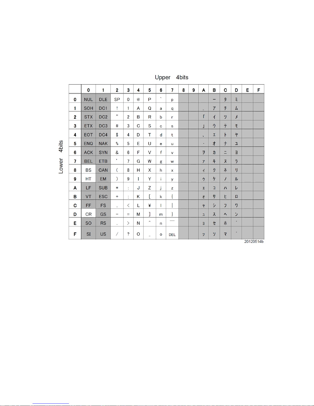
- 87 -
7.14 Table of Character code
Page 90

- 88 -
8 Specifications
Dimensions 35(H) x 55(W) x 50(D) mm
Weight Approx. 130g
Reading angle
PITCH: ± 35°
SKEW: ± 35°
TILT: 360°
Operating temparature 0 to 40°C
Operating humidity 35 to 85%R.H. (non-condensing)
Storage temperature -20 to 65°C
Storage humidity 35 to 85%R.H. (non-condensing)
[TFIR-31LAN] 5Vdc ±10%, Approx.1A Power
(Supply voltage, Power consumption)
[TFIR-31LAN-H] 5Vdc ±10%,
Approx.0.8A
Serial interface RS232C (1200 to 115.2k bps)
LAN interface Ethernet (10Base-T)
Data format ASCII
Image sensor 1/3 inch monochrome CMOS
Image format WVGA (752x480)
Digital input
1 opto-isolated
Input registance: 1kΩ
OFF voltage: 0 to 0.8Vdc
ON voltage: 6 to 28Vdc
Digital output
2 opto-isolated
Maximum rating 30Vdc 50mA
Supported symbols
1D barcode
Code39, Code128, EAN128
Codabar, ITF(Interleaved 2 of 5)
JAN / EAN / UPC, Code93, RSS
2D code
Data Matrix(ECC200), QR Code, Micro QR
PDF 417, Micro PDF, Maxi Code,
Composite, Postal(Japan Post), Aztec Code
Page 91
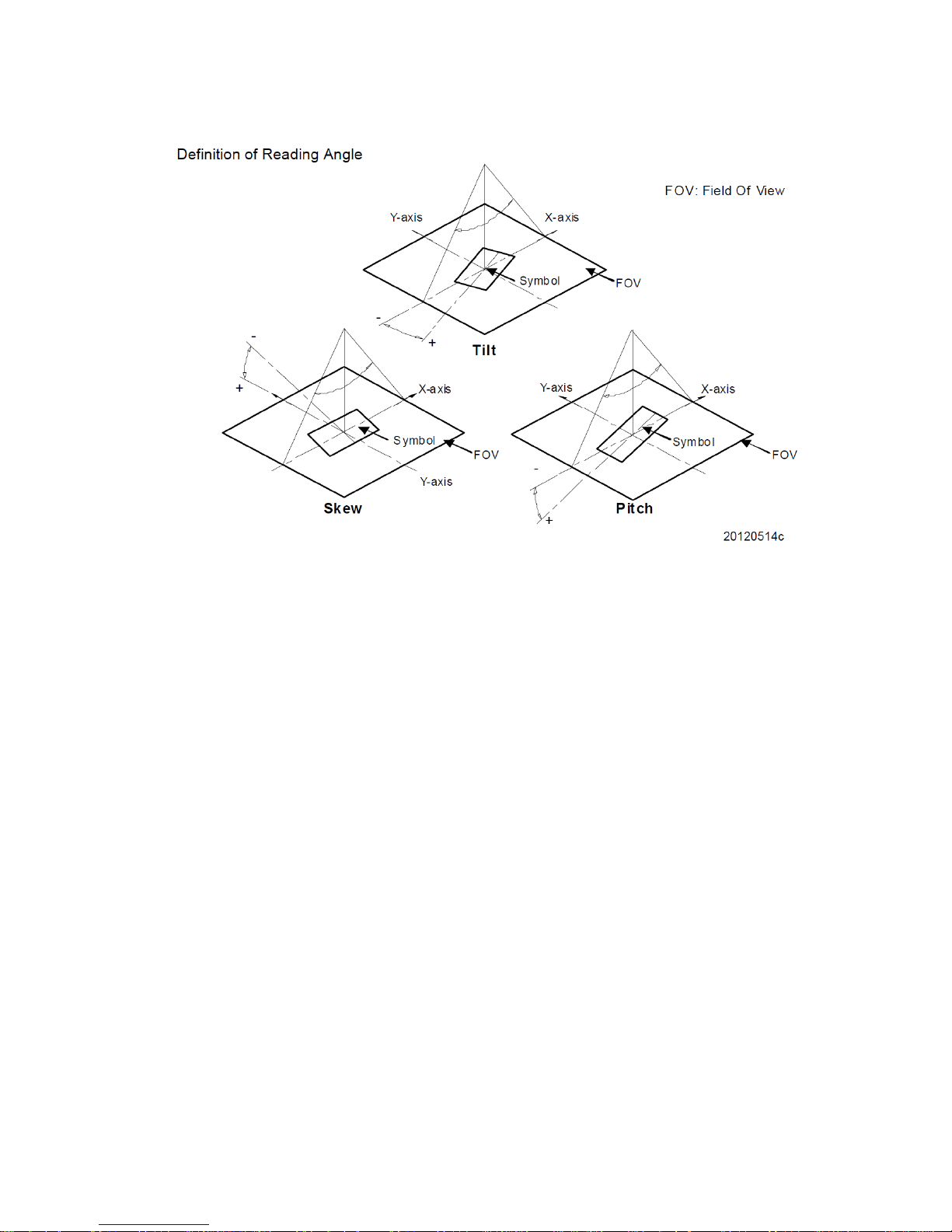
- 89 -
Page 92

- 90 -
8.1 Dimensions
55
50
63.5
17.5
35
45
10
※ ※
Teach
Read
DCBA
[Units: mm]
Mounting threaded hole: 2-M3 tapped holes, depth 5mm
Page 93

- 91 -
8.2 Interface
8.2.1 LAN interface
- Ethernet networks : 10BASE-T
- Maximum data rate : 10M bps
- Connector : RJ-45
Please use a Category 3 or better cable.
8.2.2 Interface cable
Host connector: D-sub 9-pin female connector (4-40 UNC screw locks)
Note: The above is listed realative to the reader (TFIR-31LAN) end of the
INPUT/OUTPUT transactions with the host.
DC power Jack (optional): EIAJ
Pin Name Function Direction
1 NC OPEN
2 SD Transmit data (RS232C) Output
3 RD Receive data (RS232C) Input
4 NC OPEN
5 GND GND
6 NC OPEN
7 CS Clear to send (RS232C) Input
8 RS Request to send (RS232C) Output
9 NC OPEN
Pin. Name
1 VCC (5Vdc)
2 GND
Approx. 5cm
2m
1
9
1: Inner pin
2: Outer tube
6
1 5
Page 94

- 92 -
8.2.3 DIO (Digital Input/Output)
Terminal block (opto-isolated digital input/output)
Internal Circuit Diagram
GO+
4
COM-
SYNC-
1KΩ/1W
SYNC+
NG+
1
2
3
5
Pin Name Function Direction
1 SYNC+ Sync input + Input
2 SYNC- Sync input - Input
3 GO+ OK output + Output
4 NG+ NG output + Output
5 COM- Common - Output
Page 95

- 93 -
8.3 Reading Range
8.3.1 TFIR-31LAN-H
0
10
20
30
10
20
30
2026323743
0
10
20
10
20
05040 60 7030
1316202427
ReadTeach
DCBA
[Units: mm]
Symbologies Cell size Near Far
0.125 36 54
0.167 32 58
Data Matrix
0.25 28 68
0.125 36 54
0.167 32 58
QR Code
0.25 28 68
[Units: mm]
Page 96
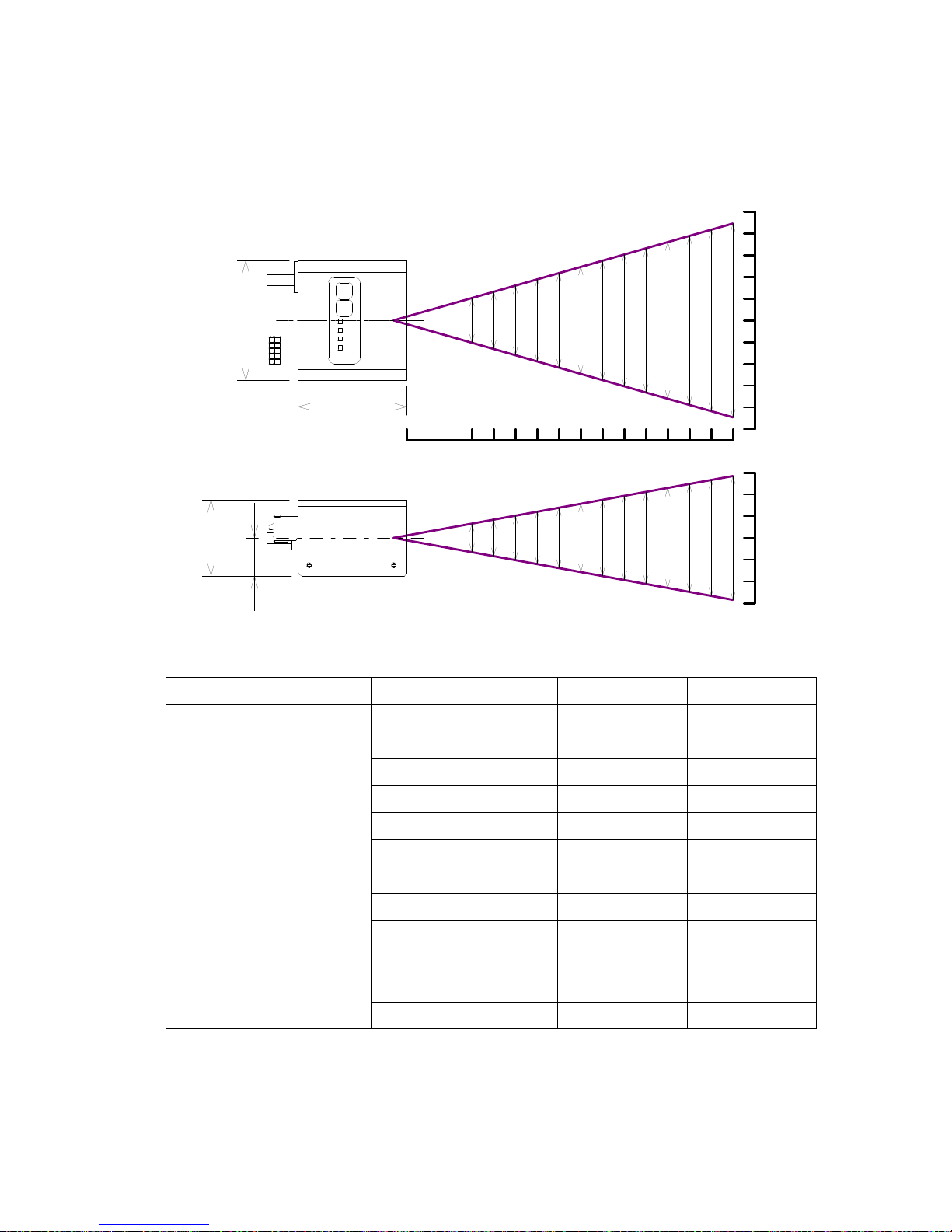
- 94 -
8.3.2 TFIR-31LAN
27
24
20
16
13
56
38
53
49
45
42
35
31
43
37
32
26
20
89
60
77
49
54
668371
0
10
20
10
20
30
30
0
10
20
30
10
20
30
40
50
40
50
05040 60 7030 80 90 100 110 120 130 140 150
55
50
35
17.5
ReadTeach
DCBA
[Units: mm]
Symbologies Cell size Near Far
0.125 50 74
0.167 43 85
0.25 40 95
0.33 30 115
0.42 25 130
Data Matrix
0.5 25 135
0.125 50 73
0.167 45 85
0.25 35 95
0.33 30 110
0.42 30 130
QR Code
0.5 30 135
[Units: mm]
Page 97
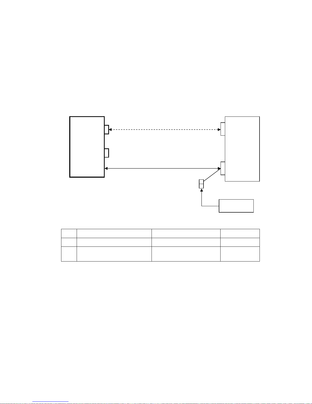
- 95 -
9 Example of configuration diagram
The followings are the conditions that are used for this configuration:
■ Reading trigger must be input by serial command
■ Does not use digital output (GO and NG)
No. Product name Model name Note
(1) AC adapter (5Vdc) KSAC0500160W1UV-1 Optional
(2) LAN cable (cross over)
Not specified (greater than
category 3)
Optional
Note: While a LAN cable is optional, the setup time of the image reader can be
reduced with its fast transfer speed.
LAN cable (cross over)
(2)
Host device
LAN
RS232C
(DSUB9P male)
(Interface cable)
AC adapter
(1)
TFIR-31LAN / -31LAN-H
DIO
LAN
Page 98

- 96 -
10 Troubleshooting
10.1 The reader does not start up or cannot communicate with a PC.
■ Is power supply voltage within the specifications?
Power supply voltage should be DC 5V ± 10%.
If the DC voltage is not within the specified range, the reader may not work
properly and there is a possibility of damaging the reader.
■ Is the host port settings the same as the reader port settings?
Make sure the connection and the communication settings (e.g. Baud rate,
Character format, COM port number for RS232C settings).
The reader port is set by the serial command “COMFROM”. If the port is set to
RS232C (COMFROM=0), both way LAN data communication between the
reader and the host would not work.
■ Is the format of serial command correct?
Serial commands input are effective in stand-by state.
Add a carriage return code [CR] at the end of the serial command.
Push the Enter key at the end to input the serial command by typing on
Terminal software.
Transmit the serial command ”WSETS” to save the settings to internal flash
memory. If the reader is turned off the power without saving settings, the reader
will start up in the previous settings next time.
An interval of 500ms between each command will avoid unwanted error during
Page 99

- 97 -
settings.
10.2 Symbol cannot be decoded
■ Is the symbol-code settings correct?
Make sure that the symbologies and the digit number are set up correctly. If the
settings differ from the input symbologies, the reader would not decode the
image.
■ Are the reading distance and the print quality suitable?
To ensure the reading distance from the code to the reading window must be
within the specified reading distance.
If the code is damaged or the print quality is low, it may not be decodable even if
the reading depth requirements have been met.
■ Is the reading window clean?
The quality of captured image is affected by the condition of the reading window.
Dust, dirt, etc. on the reading window may alter the reading performance. Clean
with a lens cleaner or similar non-abrasive method.
■ Is the print quality of the symbol good?
Make sure the quality of the symbol (1D: Module width and
Wide/Narrow bar
width ratio
, 2D: Cell size) meet the standards.
Page 100

- 98 -
■ Is ITF set to a fixed length?
When using ITF (Interleaved 2 of 5) it is possible that the number of digits read
will be less than the actual digits encoded in the barcode. We recommend
setting the specific digit length for ITF.
10.3 Fail to communicate through TCP/IP protocol
Fail to communicate through TCP/IP protocol due to accidental unplug/plugin of
the LAN cable while the reader is in working mode.
■ Retry the connection process after disconnection.
To recover the connection, send the command “discon” through RS232C
interface for forced termination, and then retry the connection.
10.4 After Good Read, the reader emits 7 short beeps a few seconds later.
Communication error can be caused by the following reasons:
- The reader is set to COMFROM=0 or 2, but a serial cable is not connected.
- The reader is set to COMFROM=1 or 2, but a LAN cable is not connected.
 Loading...