

MTS Systems Temposonics GB, Temposonics GB-J, Temposonics GB-K, Temposonics GB-N, Temposonics GB-S Brief Instructions
Page 1
Temposonics
Magnetostrictive Linear Position Sensors
Temposonics® GB-Series
Brief Instructions
®
Page 2

Temposonics® GB-Series
Brief Instructions
Table of contents
1. Introduction ..........................................................................................................................................................................3
2. Safety instructions ...............................................................................................................................................................4
2.1 Intended use ..................................................................................................................................................................4
2.2 Forseeable misuse .........................................................................................................................................................4
2.3 Installation, commissioning and operation ....................................................................................................................5
2.4 Safety instructions for use in explosion-hazardous areas ..............................................................................................5
2.5 Warranty ........................................................................................................................................................................5
2.6 Return ............................................................................................................................................................................5
2.7 Maintenance & removal .................................................................................................................................................5
3. Identification ........................................................................................................................................................................6
3.1 Temposonics
3.2 Temposonics
4. Installation & mounting .......................................................................................................................................................7
4.1 Sensor installation .........................................................................................................................................................7
4.2 Magnet installation .........................................................................................................................................................7
4.3 Mounting dimensions of GB-Series ...............................................................................................................................8
5. Electrical connection ...........................................................................................................................................................9
5.1 Analog ............................................................................................................................................................................9
5.2 SSI ...............................................................................................................................................................................10
®
GB-Series GB-J / GB-K / GB-N / GB-S (rod sensor with pressure fit flange) ..........................................6
®
GB-Series GB-M / GB-T (rod sensor with threaded flange) ....................................................................6
I 2 I
Page 3

Temposonics® GB-Series
NOTICE
Brief Instructions
1. Introduction
1.1 Purpose and use of this manual
®
Before starting the operation of Temposonics
read this documentation thoroughly and follow the safety
information. Keep the manual for future reference!
The content of this technical documentation is intended to
provide information on mounting, installation and commissioning by qualified automation personnel
service technicians who are familiar with the project planning
and dealing with Temposonics
®
sensors.
1.2 Used symbols and warnings
Warnings are intended for your personal safety and for avoidance of damage to the described product or connected devices. In this documentation, safety information and warnings to
avoid danger that might affect the life and health of operating
or service personnel or cause material damage are highlighted by the preceding pictogram which is defined below.
Symbol Meaning
This symbol is used to point to situations
that may lead to material damage, but not
to personal injury.
sensors
1
or instructed
1/ The term qualified technical personnel characterizes
persons who:
• are familiar with the safety concepts of automation
technology applicable to the particular project
• are competent in the field of electromagnetic
compatibility (EMC)
• have received adequate training for commissioning and
service operations
• are familiar with the operation of the device and know the
information required for correct operation provided in the
product documentation.
I 3 I
Page 4
Temposonics® GB-Series
Brief Instructions
2. Safety instructions
2.1 Intended use
This product may be used only for the applications defined
under item 1 only in conjunction with the third-party devices
and components recommended or approved by MTS
Sensors. As a prerequisite of proper and safe operation the
product requires correct transport, storage, mounting and
commissioning and must be operat ed with utmost care.
1. The sensor systems of all Temposonics
intended exclu sively for measurement tasks encountered
in industrial, commercial and laboratory applications.
The sensors are considered as system accessories and
must be connected to suitable evaluation electron ics,
e.g. a PLC, IPC, indicator or other electronic control unit.
2.2 Forseeable misuse
Forseeable misuse Consequence
Wrong sensor connection The sensor does not work
Operate the sensor out off
the operating temperature
Power supply is out of the
defined range
Position measurement is
influenced by an external
magnetic field
Cables are damaged Short circuit – the sensor can
Spacers are missing /
are installed in a wrong order
Wrong connection
of ground / shield
Use of a magnet that is not
certified by MTS Sensors
properly or will be destroyed
No signal output
The sensor can be damaged
Signal output is wrong /
no signal output /
the sensor will be damaged
Signal output is wrong
be destroyed / sensor does
not respond
Error in position
measurement
Signal output is disturbed
The electronics can be
damaged
Error in position
measurement
®
series are
Do not reprocess the sensor afterwards.
The sensor might be damaged.
Do not step on the sensor.
The sensor might be damaged.
Manuals, Software & 3D Models available at:
www.mtssensors.com
I 4 I
Page 5

Temposonics® GB-Series
Brief Instructions
2.3 Installation, commissioning and operation
The position sensors must be used only in technically safe
condition. To maintain this condition and to ensure safe
operation, installation, connection and service, work may
be performed only by qualified technical personnel.
If danger of injury to persons or of damage to operating
equipment is caused by sensor failure or malfunction,
additional safety measures such as plausibility checks,
limit switches, EMERGENCY STOP systems, protective
devices etc. are required. In the event of trouble, shut
down the sensor and protect it against accidental operation.
Safety instructions for commissioning
To maintain the sensor’s operability, it is mandatory to follow
the instructions given below.
1. Protect the sensor against mechanical damage during
installation and operation.
2. Do not open or dismantle the sensor.
3. Connect the sensor very carefully and pay attention
to the polarity of connections and power supply.
4. Use only approved power supplies.
5. It is indispensable to ensure that the specified
permissible limit values of the sensor for operating
voltage, environmental conditions, etc. are met.
6. Check the function of the sensor regularly and provide
documentation of the checks.
7. Before applying power, ensure that nobody’s safety
is jeopardized by starting machines.
2.4 Safety instructions for use in explosion-hazardous areas
The sensors are not suitable for operation in explosionhazardous areas.
2.5 Warranty
MTS Sensors grants a warranty period for the Temposonics
®
position sensors and supplied accessories relating to
material defects and faults that occur despite correct use in
accordance with the intended application
2
. The MTS Sensors
obligation is limited to repair or replacement of any defective
part of the unit. No warranty can be provided for defects
that are due to improper use or above average stress of the
product, as well as for wear parts. Under no circumstances
will MTS Sensors accept liability in the event of offense
against the warranty rules, no matter if these have been
assured or expected, even in case of fault or negligence of
the company.
MTS Sensors explicitly excludes any further warranties.
Neither the company’s representatives, agents, dealers nor
employees are authorized to increase or change the scope
of warranty.
2.6 Return
For diagnostic purposes, the sensor can be returned to MTS
Sensors. Any shipment cost is the responsibility of the send-
2
er
. For a corresponding form, see detailed operation manual
(available at: www.mtssensors.com).
2.7 Maintenance & removal
Maintenance
The sensor is maintenance-free.
Repair
Repairs on the sensor may be performed only by MTS Sensors
or a repair facility explicitly authorized by MTS Sensors.
List of spare parts
No spare parts are available for this sensor.
2/ See also applicable MTS Sensors sales and supply
conditions, e.g. at www.mtssensors.com
Transport and storage
The conditions of transport and storage of the sensor match
the operating conditions mentioned in this document.
Removal from service / dismantling
The product contains electronic components and must be
disposed of in accordance with the local regulations.
I 5 I
Page 6

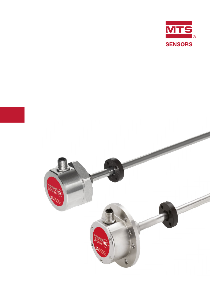
Temposonics® GB-Series
Stroke length (e.g. 850 mm)
rod (Ø 10 mm / Ø 12.7 mm)
Brief Instructions
3. Identification
Nameplate (e.g. GB-Series GB-S Analog)
Sensor model
Part no.
Output
Production no.
3.1 Temposonics® GB-Series with pressure fit flange (GB-J / GB-K / GB-N / GB-S)
Connector or
cable outlet
GBS0850MD601A0SC
4 - 20 mA
FNr. 1601 0376
1601037616010376160103761601
Position magnet
(Ring or U-magnet)
Pressure fit flange Ø 18 mm / Ø 21 mm
Fastened via 6 machine
screws M6 (ISO 4762)
Fastening torque: 6 Nm
Connection type
Output
version
Year
Week
Pressure-proof
with sensor
element
Approvals and certificates
You will find approvals and certificates in the sensor specific
operation manuals.
Available outputs:
• Analog
• SSI
3.2 Temposonics® GB-Series GB-M / GB-T with threaded flange (GB-M / GB-T)
Position magnet
Connector or
cable outlet
(Ring or U-magnet)
Pressure-proof
rod (Ø 10 mm)
with sensor
element
Threaded flange
(M18×1.5-6g or
¾"-16 UNF-3A)
Fastened with 3 screws DIN 915 M4×6 A2
Fastening torque: 1.6 Nm
Manuals, Software & 3D Models available at:
www.mtssensors.com
I 6 I
Available outputs:
• Analog
• SSI
Page 7

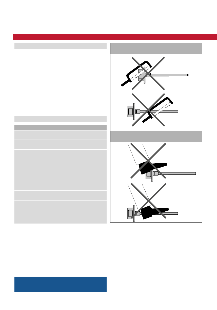
Concentric mounting
4. Installation & mounting
4.1 Sensor installation
General
• Seat the flange contact surface completely on the cylinder
mounting surface.
• The cylinder manufacturer determines the pressureresistant gasket (copper gasket, O-ring, etc.).
• The position magnet should not grind on the sensor rod.
• The piston rod drilling (≥ Ø 13 mm / for GB-J and GB-K
sensors: ≥ Ø 16 mm) depends on the pressure and piston
speed.
• Adhere to the information relating to operating pressure.
• Protect the sensor rod against wear.
4.2 Magnet installation
Typical use of magnets
• Rotationally symmetrical magnetic field
Ring magnet
• The magnet can be lifted off
U-magnet
• Height tolerances can be compensated
Temposonics® GB-Series
Brief Instructions
GB-Series with pressure fit flange
Mount the sensor via the fitting flange through the bores
in the sensor electronics housing with 6 machine screws
M6×16 A2-70 (ISO 4762). Note the fastening torque of 6 Nm.
The hydraulic sealing requires the use of a supplied O-ring
15 × 2 mm (GB-J: 17 x 2 mm).
GB-Series with threaded flange
Mount the sensor via the threaded flange M18×1.5-6g or
¾"-16 UNF-3A. Note the fastening torque of 50 Nm.
Notice for sensors with stroke lengths ≥ 1 meter
Support horizontally installed sensors with a stroke length
from 1 meter mechanically at the rod end. Without the use of
a support, rod and position magnet may be damaged. A false
measurement is also possible. Longer rods require evenly
distributed mechanical support over the entire length. Use an
U-magnet for measurement.
Sensor support (for sensors with stroke length ≥ 1 meter)
U-magnet
Sensor rod
Non-magnetic fixing clip
NOTICE
For detailed mounting instructions see operation manual.
Install the magnet using non-magnetic material for mounting
device, screws, spacers etc.. The magnet must not grind on
the sensor rod. Alignment errors are compensated via the
air gap.
• Max. permissible surface pressure: 40 N/mm
• Fastening torque for M4 screws: 1 Nm; use washers,
if necessary
• Minimum distance between position magnet and any
magnetic material has to be 15 mm.
• If no other option exists and magnetic material is used,
observe the specified dimensions.
2
NOTICE
Mount the ring magnet and U-magnet concentrically.
The maximum permissible air gap must not be exceeded.
Concentric mounting of U-magnet
M4
2
1
of U-magnet
Air gap
Part no. 251 416-2:
1.75 ±1 (0.07 ±0.04)
1
U-magnet
2
Non-magnetic mounting device and screws
All dimensions in mm
Manuals, Software & 3D Models available at:
www.mtssensors.com
I 7 I
Page 8

Temposonics® GB-Series
A B
Brief Instructions
Magnet mounting with magnetic material
Magnetic
1
material
2
Magnet
Null zone, depends on sensor model
1
Distance between position magnet and any magnetic
2
material (≥ 15 mm)
Non-magnetic spacer (≥ 5 mm) –
3
Recommendation: 8 mm
Magnet mounting with magnetic material
A. If the position magnet aligns with the drilled piston rod
B. If the position magnet is set further into the drilled piston
rod, install another non-magnetic spacer above the magnet
3 3
Magnet
4.3 Mounting dimensions of GB-Series
GB-Series with pressure fit flange
with ring / U-magnet
Reference edge of mounting
Start position
40 Stroke length 63.5
GB-Series with threaded flange with ring / U-magnet
Reference edge of mounting
Start position
40 Stroke length 63.5
NOTICE
On all sensors, the areas left and right of the active stroke
length are provided for mounting and damping of the measuring signal. They could not be used for measurement,
but the active stroke length can be exceeded.
Manuals, Software & 3D Models available at:
www.mtssensors.com
All dimensions in mm
I 8 I
Page 9

5. Electrical connection
on the sensor’s electromagnetic compatibility (EMC). Hence
correct installation of this active electronic system and the
EMC of the entire system must be ensured by using suitable
metal connectors, shielded cables and grounding. Overvoltages or faulty connections can damage its electronics despite
protection against wrong polarity.
NOTICE
Never connect / disconnect the sensor when voltage is
applied.
Instructions for connection
• Use low-resistant twisted pair and shielded cables and
connect the shield to ground externally via the controller
equipment.
• Keep control and sign leads separate from power cables
and sufficiently far away from motor cables, frequency
inverters, valve lines, relays, etc..
• Use only connectors with metal housing and connect the
shielding to the connector housing.
• Keep the connection surface at both shielding ends as
large as possible.
• Keep all non-shielded leads as short as possible.
• Keep the earth connection as short as possible with a
large cross section. Avoid ground loops.
• With potential differences between machine and electronics
earth connections, no compensating currents are allowed
to flow across the cable shielding.
Recommendation:
Install potential compensating leads with large cross
section, or use cables with separate double shielding,
and connect only one end of the shield.
• Use only stabilized power supplies in compliance with
the specified connecting values.
Temposonics® GB-Series
Brief Instructions
5.1 AnalogPlacement of installation and cabling have decisive influence
D34 (for outputs: V0, A0, A1, A2, A3 in order code)
Signal + power supply
M12 male connector
(A-coded)
2
345
View on sensor
* Connection necessary for programming with hand or cabinet
programmer
D34 (for output: A4 in order code)
Signal + power supply
M12 male connector
(A-coded)
2
345
View on sensor
* Connect the fi rst output (4…20 mA) at low-resistance,
if you only use the second output (20…4 mA)
Pin Voltage Current
+24 VDC
1
(−15 / +20 %)
2 0…10 VDC
1
3 DC Ground (0 V) DC Ground (0 V)
4 10…0 VDC Not connected
5 DC Ground DC Ground
Pin Current
1 +24 VDC (−15 / +20 %)
*
1
2 4…20 mA
3 DC Ground (0 V)
4 20…4 mA
5 DC Ground
+24 VDC
(−15 / +20 %)
4(0)…20 mA or
20… 4(0) mA
*
NOTICE
Do not mount the sensors in an area of strong magnetic or
electric noise fields.
NOTICE
Connect the sensor electronics housing to the machine
ground via pressure fit flange respectively via threaded
flange.
I 9 I
Page 10

Temposonics® GB-Series
Brief Instructions
D60 (for outputs: V0, A0, A1, A2, A3 in order code)
Signal + power supply
M16 male connector Pin Voltage Current
*
4(0)…20 mA or
20… 4(0) mA
+24 VDC
(−15 / +20 %)
1 0…10 VDC
1
2
6
3
4
View on sensor
* Connection necessary for programming with hand or cabinet
programmer
D60 (for output: A4 in order code)
Signal + power supply
M16 male connector Pin Current
1
2
6
3
4
View on sensor
* Connect the fi rst output (4…20 mA) at low-resistance,
if you only use the second output (20…4 mA)
2 DC Ground DC Ground
3 10…0 VDC Not connected
5
4 DC Ground DC Ground
+24 VDC
5
(−15 / +20 %)
6 DC Ground (0 V) DC Ground (0 V)
1 4…20 mA
2 DC Ground
3 20…4 mA
5
4 DC Ground
5 +24 VDC (−15 / +20 %)
6 DC Ground (0 V)
HXX / TXX / VXX (for outputs: V0, A0, A1, A2, A3 in order code)
Signal + power supply
Cable Color Voltage Current
GY 0…10 VDC
PK DC Ground DC Ground
*
* Connection necessary for programming with hand or cabinet
programmer
HXX / TXX / VXX (for output: A4 in order code)
Signal + power supply
Cable Color Current
* Connect the fi rst output (4…20 mA) at low-resistance,
if you only use the second output (20…4 mA)
YE 10…0 VDC Not connected
GN DC Ground DC Ground
+24 VDC
BN
(−15 / +20 %)
WH DC Ground (0 V) DC Ground (0 V)
GY 4…20 mA
PK DC Ground
YE 20…4 mA
GN DC Ground
BN +24 VDC (−15 / +20 %)
WH DC Ground (0 V)
*
4(0)…20 mA or
20… 4(0) mA
+24 VDC
(−15 / +20 %)
*
I 10 I
NOTICE
DANGER OF SHORT-CIRCUIT!
Insulate the conductors of the second output (yellow,
green), if you only use the first output. We recommend
providing terminals for the second output in the
control cabinet, since the leads are required for sensor
programming.
Page 11

5.2 SSI
D84
Signal + power supply
M12 male connector
(A-coded)
2
3
1
4
8
7
5
6
View on sensor
D70
Signal + power supply
M16 male connector Color Function
6
1
7
4
3
2
5
View on sensor
Pin Function
1 Clock (+)
2 Clock (−)
3 Data (+)
4 Data (−)
5 Not connected
6 Not connected
7 +24 VDC (−15 / +20 %)
8 DC Ground (0 V)
1 Data (−)
2 Data (+)
3 Clock (+)
4 Clock (−)
5 +24 VDC (−15 / +20 %)
6 DC Ground (0 V)
7 Not connected
Temposonics® GB-Series
Brief Instructions
GB with cable outlet (HXX / TXX / VXX)
Signal + power supply
Cable Color Function
GY Data (−)
PK Data (+)
YE Clock (+)
GN Clock (−)
BN +24 VDC (−15 / +20 %)
WH DC Ground (0 V)
NOTICE
Connect the sensor electronics housing to the machine
ground via fitting flange respectively via threaded flange.
I 11 I
Page 12

Reg.-No. 003095-QM08
Temposonics® GB-Series
Brief Instructions
Notes
The sensor is also available with Bluetooth
connection. For more information see document:
“Programming & Configuration via Bluetooth
®
®
”
Document part number for GB-Series analog: 551595
Document part number for GB-Series SSI: 551649
I 12 I
Page 13

UNITED STATES
Reg.-No. 003095-QM08
MTS Systems Corporation
Sensors Division
GERMANY
MTS Sensor Technologie
GmbH & Co. KG
ITALY
Branch Offi ce
FRANCE
Branch Offi ce
3001 Sheldon Drive
Cary, N.C. 27513
Phone: +1 919 677-0100
E-mail: info.us@mtssensors.com
Auf dem Schüffel 9
58513 Lüdenscheid
Phone: +49 2351 9587-0
E-mail: info.de@mtssensors.com
Phone: +39 030 988 3819
E-mail: info.it@mtssensors.com
Phone: +33 1 58 4390-28
E-mail: info.fr@mtssensors.com
Document Part Number
551727 Revision C (EN) 07/2018
GREAT BRITAIN
Branch Offi ce
Branch Offi ce
Branch Offi ce
Phone: +44 79 44 15 03 00
E-mail: info.uk@mtssensors.com
Phone: +86 21 6485 5800
CHINA
E-mail: info.cn@mtssensors.com
Phone: +81 42 707 7710
JAPAN
E-mail: info.jp@mtssensors.com
www.mtssensors.com
MTS, Temposonics and Level Plus are registered trademarks of MTS Systems Corporation in the United States; MTS SENSORS and the MTS SENSORS logo are trademarks of MTS Systems Corporation within the
United States. These trademarks may be protected in other countries. All other trademarks are the property of their respective owners. Copyright © 2018 MTS Systems Corporation. No license of any intellectual
property rights is granted. MTS reserves the right to change the information within this document, change product designs, or withdraw products from availability for purchase without notice. Typographic and
graphics errors or omissions are unintentional and subject to correction. Visit www.mtssensors.com for the latest product information.
 Loading...