

Page 1

R-Series V EtherNet/IP™
Operation Manual
Temposonics
®
Magnetostrictive Linear Position Sensors
GENERATION
I AM
V
THE NEW
Page 2

Temposonics® R-Series V EtherNet/IP™
Operation Manual
Table of contents
1. Introduction ..................................................................................................................................................... 3
1.1 Purpose and use of this manual ................................................................................................................................................................ 3
1.2 Used symbols and warnings ..................................................................................................................................................................... 3
2. Safety instructions ............................................................................................................................................. 3
2.1 Intended use .............................................................................................................................................................................................. 3
2.2 Foreseeable misuse ................................................................................................................................................................................... 3
2.3 Installation, commissioning and operation ................................................................................................................................................ 4
2.4 Safety instructions for use in explosion-hazardous areas .......................................................................................................................... 4
2.5 Warranty .................................................................................................................................................................................................... 4
2.6 Return ....................................................................................................................................................................................................... 4
3. Identification.................................................................................................................................................... 5
3.1 Order code of Temposonics
®
R-Series V RP............................................................................................................................................. 5
3.2 Order code of Temposonics
®
R-Series V RH ............................................................................................................................................ 6
3.3 Nameplate ................................................................................................................................................................................................. 7
3.4 Approvals .................................................................................................................................................................................................. 7
3.5 Scope of delivery ....................................................................................................................................................................................... 7
4. Product description and commissioning ................................................................................................................... 8
4.1 Functionality and system design ............................................................................................................................................................... 8
4.2 Styles and installation of Temposonics
®
R-Series V RP ........................................................................................................................... 9
4.3 Styles and installation of Temposonics
®
R-Series V RH ......................................................................................................................... 10
4.4 Magnet installation .................................................................................................................................................................................. 13
4.5 Replacement of sensor ............................................................................................................................................................................ 16
4.6 Electrical connections .............................................................................................................................................................................. 17
4.7 Frequently ordered accessories ............................................................................................................................................................... 19
5. Operation.......................................................................................................................................................22
5.1 LED Status ............................................................................................................................................................................................... 22
6. Programming and configuration ............................................................................................................................ 23
6.1 IP address Configuration ......................................................................................................................................................................... 23
6.2 Setting the IP address of the sensor ........................................................................................................................................................ 23
7. Integration in RSLogix 5000 ................................................................................................................................25
7.1 Install the MTS EtherNet/IP™ EDS file ..................................................................................................................................................... 25
7.2 Add sensor to I/O configuration using EDS file ....................................................................................................................................... 27
7.3 Add sensor to I/O configuration without using EDS file ........................................................................................................................... 28
7.4 Set Module RPI ....................................................................................................................................................................................... 29
7.5 Verify Generic EtherNet Module ............................................................................................................................................................... 29
7.6 Verify Generic Ethernet Module ............................................................................................................................................................... 30
7.7 Controller tags input data ........................................................................................................................................................................ 32
8. Maintenance and troubleshooting .........................................................................................................................33
8.1 Error conditions, troubleshooting ............................................................................................................................................................ 33
8.2 Maintenance ............................................................................................................................................................................................ 33
8.3 Repair ...................................................................................................................................................................................................... 33
8.4 List of spare parts ................................................................................................................................................................................... 33
8.5 Transport and storage .............................................................................................................................................................................33
9. Removal from service / dismantling ....................................................................................................................... 33
10. Technical data ...............................................................................................................................................34
9.1 Technical data Temposonics
®
R-Series V RP .......................................................................................................................................... 34
9.2 Technical data Temposonics
®
R-Series V RH ......................................................................................................................................... 35
11. Appendix I ....................................................................................................................................................36
12. Appendix II ...................................................................................................................................................37
Page 3

Temposonics® R-Series V EtherNet/IP™
Operation Manual
I 3 I
1. Introduction
1.1 Purpose and use of this manual
Before starting the operation of Temposonics
®
position sensors,
read this documentation thoroughly and follow the safety
information. Keep this manual for future reference!
Symbol Meaning
NOTICE
This symbol is used to point to situations
that may lead to material damage, but not
to personal injury.
1/ The term "qualified technical personnel" characterizes persons who
• are familiar with the safety concepts of automation technology applicable
to the particular project and
• are competent in the field of electromagnetic compatibility (EMC) or
• have received adequate training for commissioning and service operations or
• and are familiar with the operation of the device and know the information required
for correct operation provided in the product documentation
2. Safety instructions
2.1 Intended use
This product may be used only for the applications defined under item
1 and only in conjunction with the third-party devices and components
recommended or approved by MTS Sensors. As a prerequsite of
proper and safe operation the product requires correct transport,
storage, mounting and commissioning and must be operat ed with
utmost care.
1. The sensor systems of all Temposonics
®
series are intended
exclu sively for measurement tasks encountered in industrial,
commercial and laboratory applications. The sensors are
considered as system accessories and must be connected
to suitable evaluation electron ics, e.g. a PLC, IPC, indicator
or other electronic control unit.
Foreseeable misuse Consequence
Wrong sensor connection
The sensor will not work
properly or can be damaged
Operate the sensor out of the
operating temperature range
No signal output
The sensor can be damaged
Power supply is out of the
defi ned range
Signal output is wrong /
no signal output /
the sensor can be damaged
Position measurement is
infl uenced by an external
magnetic fi eld
Signal output is wrong
Cables are damaged
Short circuit – the sensor can
be destroyed / sensor does not
respond
Spacers are missing /
are installed in the wrong order
Error in position measurement
Wrong connection
of ground / shield
Signal output is disturbed
The electronics can be damaged
Use of a magnet that is not
certifi ed by MTS Sensors
Error in position measurement
Do not alter the sensor afterwards.
The sensor might be damaged.
Do not step on the sensor.
The sensor might be damaged.
2.2 Foreseeable misuse
The content of this technical documentation and of its appendix
is intended to provide information on mounting, installation and
commissioning by qualified automation personnel
1
or instructed
service technicians who are familiar with the project planning and
dealing with Temposonics
®
sensors.
1.2 Used symbols and warnings
Warnings are intended for your personal safety and for avoidance
of damage to the described product or connected devices. In this
documentation, safety information and warnings to avoid danger
that might affect the life and health of operating or service personnel
or cause material damage are highlighted by the pictogram defined
below.
Page 4

Temposonics® R-Series V EtherNet/IP™
Operation Manual
I 4 I
2.3 Installation, commissioning and operation
The position sensors must be used only in technically safe conditions.
To maintain this condition and to ensure safe operation, installation,
connection and service, work may be performed only by qualified
technical personnel.
If danger of injury to persons or of damage to operating equipment
is caused by sensor failure or malfunction, additional safety measures
such as plausibility checks, limit switches, EMERGENCY STOP
systems, protective devices etc. are required. In the event of trouble,
shut down the sensor and protect it against accidental operation.
Safety instructions for commissioning
To maintain the sensor's operability, it is mandatory to follow
the instructions given below.
1. Protect the sensor against mechanical damage during
installation and operation.
2. Do not open or dismantle the sensor.
3. Connect the sensor very carefully and pay attention to the
polarity of connections and power supply.
4. Use only approved power supplies.
5. Ensure the sensor is operating within the defined limits for supply
voltage, environmental conditions, etc.
6. Check the function of the sensor regularly and provide
documentation of the checks.
7. Before applying power, ensure that nobody’s safety
is jeopardized by starting machines.
2.4 Safety instructions for use in explosion-hazardous areas
The sensor is not suitable for operation in explosion-hazardous areas.
2/ See also applicable MTS Sensors terms of sales and delivery on:
www.mtssensors.com
2.5 Warranty
MTS Sensors grants a warranty period for the Temposonics
®
position sensors and supplied accessories relating to material
defects and faults that occur despite correct use in accordance with
the intended application
2
. The MTS Sensors obligation is limited to
repair or replacement of any defective part of the unit. No warranty
can be provided for defects that are due to improper use or above
average stress of the product, as well as for wear parts. Under no
circumstances will MTS Sensors accept liability in the event of offense
against the warranty rules, no matter if these have been assured or
expected, even in case of fault or negligence of the company.
MTS Sensors explicitly excludes any further warranties. Neither
the company’s representatives, agents, dealers nor employees are
authorized to increase or change the scope of warranty.
2.6 Return
For diagnostic purposes, the sensor can be returned to MTS Sensors
or a repair facility explicitly authorized by MTS Sensors. Any shipment
cost is the responsibility of the sender
2
. For a corresponding form,
see chapter "11. Appendix I" on page 36.
Page 5

Temposonics® R-Series V EtherNet/IP™
Operation Manual
I 5 I
3.1 Order code of Temposonics® R-Series V RP
3. Identification
1 2 3 4 5 6 7 8 9 10 11 12 13 14 15 16 17 18 19 20
R P 5 D 5 1 U 2
a b c d e f g h
b Design
G
Magnet slider, backlash free (part no. 253 421)
L
Block magnet L (part no. 403 448)
M
U-magnet, OD33 (part no. 251 416-2)
N
Magnet slider, longer ball-jointed arm (part no. 252 183)
O
No position magnet
S
Magnet slider, joint at top (part no. 252
182)
V
Magnet slider, joint at front (part no. 252
184)
a Sensor model
R P
5
Profile
*/ Non standard stroke lengths are available; must be encoded in 5 mm / 0.1 in. increments
d Stroke length
X X X X M
0025…6350 mm
X X X X
U
001.0…250.0 in.
Standard stroke length (in.)* Ordering steps
1 … 20 in. 1 in.
20…100 in. 2 in.
100…200 in. 4 in.
200…250 in. 10 in.
.
Standard stroke length (mm)* Ordering steps
25 … 500 mm 25 mm
500…2500 mm 50 mm
2500…5000 mm 100 mm
5000…6350 mm 250 mm
c Mechanical options
A
Standard
V
Fluorelastomer seals for the electronics housing
g System
1
Standard
f Connection type
D 5 6
2 × M12 female connectors (5 pin),
1 × M8 male connector (4 pin)
D 5 8
2 × M12 female connectors (5 pin),
1 × M12 male connector (4 pin)
h Output
U 2 0 1
EtherNet/IP™, position and velocity
(1…20 positions)
U 2 1 1
EtherNet/IP™, position and velocity,
internal linearization (1…20 positions)
e Number of magnets
X X
01…20 Position(s) (1…20 magnet(s))
NOTICE
• For applications using more than 1 magnet, order the
additionalmagnets separately.
• The number of magnets is limited by the stroke length.
The minimum allowed distance between magnets (i.e. front face
of one to the front face of the next one) is 75 mm (3 in.).
• Use magnets of the same type for multi-position measurement,
e.g. 2 × U-magnets (part no. 251 416-2).
Page 6
Temposonics® R-Series V EtherNet/IP™
Operation Manual
I 6 I
3.2 Order code of Temposonics® R-Series V RH
a Sensor model
R H 5 Rod
1 2 3 4 5 6 7 8 9 10 11 12 13 14 15 16 17 18 19 20
R H 5
D 5 1
U
2
a b c d e f g
h
b Design
B
Base unit (only for replacement)
J
Threaded flange M22×1.5-6g (rod Ø 12.7 mm, 800 bar)
M
Threaded flange M18×1.5-6g (standard)
S
Threaded flange ¾"×16UNF - 3A (standard)
T
Threaded flange ¾"×16UNF - 3A (with raised-face)
c Mechanical options
A Standard
B Bushing on rod end (only for flange option »M«, »S« & »T«)
M Thread M4 at rod end (only for flange option »M«, »S« & »T«)
V Fluorelastomer seals for the electronics housing
Standard stroke length (in.)* Ordering steps
1 … 20 in. 0.2 in.
20 … 30 in. 0.4 in.
30 … 40 in. 1.0 in.
40…100 in. 2.0 in.
100…200 in. 4.0 in.
200…300 in. 10.0 in.
d Stroke length
X X X X M
0025…7620 mm
X X X X
U
001.0…300.0 in.
.
Standard stroke length (mm)* Ordering steps
25 … 500 mm 5 mm
500 … 750 mm 10 mm
750…1000 mm 25 mm
1000…2500 mm 50 mm
2500…5000 mm 100 mm
5000…7620 mm 250 mm
g System
1
Standard
*/ Non standard stroke lengths are available; must be encoded in 5 mm / 0.1 in. increments
f Connection type
D 5 6
2 × M12 female connectors (5 pin),
1 × M8 male connector (4 pin)
D 5 8
2 × M12 female connectors (5 pin),
1 × M12 male connector (4 pin)
h Output
U 2 0 1
EtherNet/IP™, position and velocity
(1…20 positions)
U
2
1 1
EtherNet/IP™, position and velocity,
internal linearization (1…20 positions)
e Number of magnets
X X
01…20 Position(s) (1…20 magnet(s))
NOTICE
• For applications using more than 1 magnet, order the
additionalmagnets separately.
• The number of magnets is limited by the stroke length.
The minimum allowed distance between magnets (i.e. front face
of one to the front face of the next one) is 75 mm (3 in.).
• Use magnets of the same type for multi-position measurement,
e.g. 2 × U-magnets (part no. 251 416-2).
Page 7
Temposonics® R-Series V EtherNet/IP™
Operation Manual
I 7 I
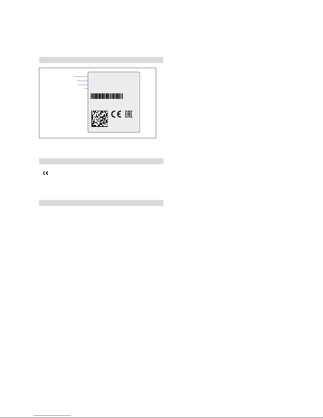
3.3 Nameplate
Fig. 1: Example of nameplate of a R-Series V RH5 sensor with EtherNet/IP™ output
3.4 Approvals
•
certified
• EAC certified
• ODVA certified
3.5 Scope of delivery
RP5 (profile sensor):
• Sensor
• Position magnet
• 2 mounting clamps up to 1250 mm (50 in.) stroke length +
1 mounting clamp for each 500 mm (20 in.) additional stroke length
RH5 (rod sensor):
• RH5-B: Base unit, 3 socket screws M4
• RH5-J/M/S/T: Sensor, O-ring
RH5SA0080U01D561U201
MAC: 00-03-CA-00-58-F6
S/N: 15030203
12JAN2018
Order code
MAC address
Date of Production
Serial number
Page 8
Temposonics® R-Series V EtherNet/IP™
Operation Manual
I 8 I
4. Product description and commissioning
4.1 Functionality and system design
Product designation
• Position sensor Temposonics® R-Series V
Sensor model
• Temposonics® R-Series V RP (profile sensor)
• Temposonics
®
R-Series V RH (rod sensor)
Stroke length
• Temposonics® R-Series V RP 25…6350 mm (1…250 in.)
• Temposonics
®
R-Series V RH 25…7620 mm (1…300 in.)
Output signal
• EtherNet/IP™
Application
The Temposonics
®
position sensors are used for measurement and
conversion of the length (position) variable in the fields of automated
systems and mechanical engineering.
Principle of operation and system construction
The absolute, linear position sensors provided by MTS Sensors
rely on the company’s proprietary Temposonics
®
magnetostrictive
technology, which can determine position with a high level of precision
and robustness. Each Temposonics
®
position sensor consists of a
ferromagnetic waveguide, a position magnet, a strain pulse converter
and supporting electronics. The magnet, connected to the object in
motion in the application, generates a magnetic field at its location on
the waveguide. A short current pulse is applied to the waveguide.
This creates a momentary radial magnetic field and torsional strain
on the waveguide. The momentary interaction of the magnetic
fields releases a torsional strain pulse that propagates the length
of the waveguide. When the ultrasonic wave reaches the end of the
waveguide it is converted into an electrical signal. Since the speed
of the ultrasonic wave in the waveguide is precisely known, the time
required to receive the return signal can be converted into a linear
position measurement with both high accuracy and repeatability.
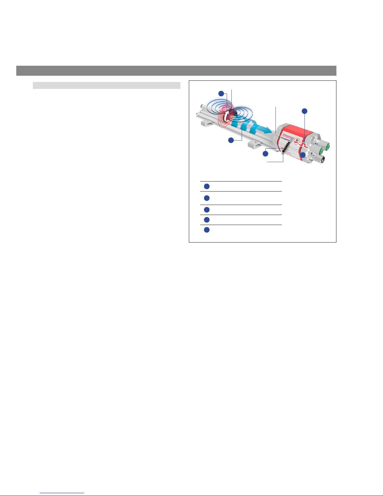
Fig. 2: Time-based magnetostrictive position sensing principle
Modular mechanical and electronic construction
• The sensor rod or profile protects the inner sensor element.
• The sensor electronics housing, a rugged aluminum construction,
contains the complete electronic interface with active signal
conditioning. Double shielding ensures high safety of operation and
optimum EMC (Electromagnetic Compatibility).
• The external position magnet is a permanent magnet. Mounted on
the mobile machine part, it travels along the sensor rod or profile
and triggers the measurement through the sensor rod wall.
• The sensor can be connected directly to a control system.
Its electronics generates a strictly position-proportional signal
output between start and end position.
5
3
1
Measurement Cycle
1 Current pulse generates magnetic eld
2
Interaction with position magnet eld
generates torsional strain pulse
3 Torsional strain pulse propagates
4 Strain pulse detected by converter
5 Time-of- ight converted into position
Sensing element (Waveguide)
Position magnet (Magnetic eld)
Torsional strain pulse converter
2
4
Page 9
Temposonics® R-Series V EtherNet/IP™
Operation Manual
I 9 I
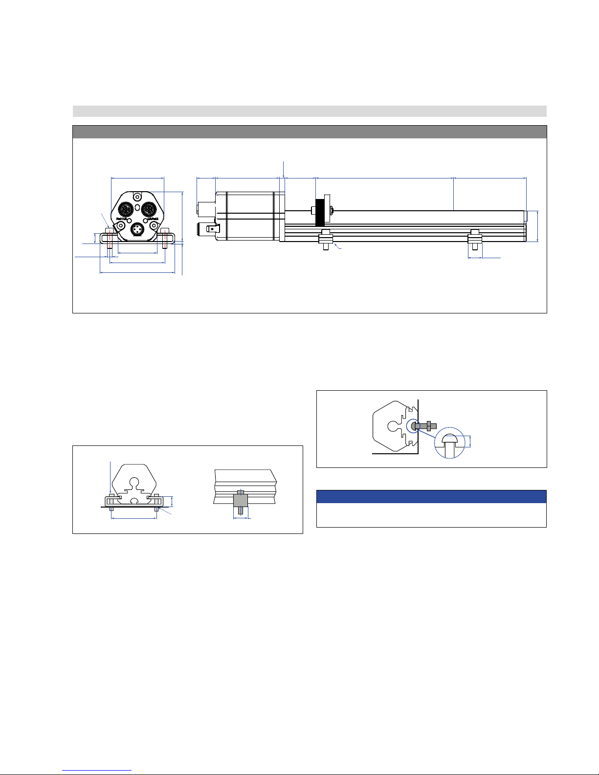
4.2 Styles and installation of Temposonics® R-Series V RP
Fig. 3: Temposonics® RP5 with U-magnet
RP5-M (connection type D58)
45 (1.77)
9.5 (0.37)
48 (1.89)
50 (1.97)
68 (2.68)
Sensor electronics housing
58
(2.28)
17
(0.67)
Null zone
28 (1.1)
Dead zone
66 / 71*
(2.6 / 2.8*)
2 (0.08)
Ø 5.5
(Ø 0.22)
35.6 (1.4)
* Stroke length > 5000 mm (196.9 in.)
28
(1.1)
14.5
(0.57)
Adjustable mounting clamp
e.g. for
M5 or
#10 screws
5
(0.2)
Magnet
Stroke length
25…6350
(1…250)
Controlling design dimensions are in millimeters and measurements in ( ) are in inches
Controlling design dimensions are in millimeters and measurements in ( ) are in inches
Installation of RP5
The position sensor can be installed in any position. Normally,
the sensor is firmly installed and the position magnet is fastened
to the mobile machine part. Thus it can travel along the sensor profile.
The sensor is fitted on a flat machine surface using the mounting
clamps (Fig. 4). A length-dependent number of these clamps are
delivered with the sensor and must be distributed over the profile
at regular distances. For fastening use M5×20 screws to DIN 6912
that should be tightened with a fastening torque of 5 Nm.
Fig. 4: Mounting clamps (part no. 400 802) with cylinder screw M5×20
Fig. 5: T-slot nut M5 (part no. 401 602)
NOTICE
Take care to mount the sensor in an axially parallel position to
avoid damage to magnet and sensor.
≤ 5
(≤
0.2)
M5
Alternative:
If only limited space is available, the profile sensor can be mounted
also via the T-rail in the profile bottom using an T-slot nut M5
(part no. 401 602) or a sliding block (Fig. 5).
Fastening torque: 5 Nm
50
(1.97)
9.5
(0.38)
Bore Ø 5.5
(Ø 0.27)
14.5
(0.57)
Page 10
Temposonics® R-Series V EtherNet/IP™
Operation Manual
I 10 I
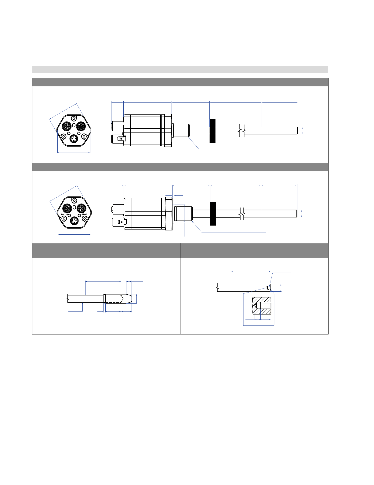
4.3 Styles and installation of Temposonics® R-Series V RH
Controlling design dimensions are in millimeters and measurements in ( ) are in inches
Fig. 6: Temposonics
®
RH5 with ring magnet, part 1
RH5-M/S-A/-V – RH5 with threaded flange M18×1.5 or ¾"×16UNF (connection type D58)
Port 1 L/A L/A Port 2
A/F 46
48
(1.89)
17
(0.67)
Sensor electronics housing
68
(2.68)
Null zone
51
(2.01)
Threaded flange »M«: M18×1.5-6g
Threaded flange »S«: ¾"-16 UNF-3A
Magnet
Dead zone
63.5 / 66*
(2.5 / 2.6*)
Stroke length
25…7620
(1…300)
Ø 10 ±0.13
(Ø 0.39 ±0.01)
* Stroke length > 5000 mm (196.9 in.)
RH5-T-A/-V – RH5 with threaded, raised face flange ¾“×16UNF (connection type D58)
A/F 46
48
(1.89)
17
(0.67)
Ø 25.4
(Ø 1)
Threaded flange »T«: ¾"-16 UNF-3A
Stroke length
25…7620
(1…300)
Sensor electronics housing
65.11
(2.56)
Null zone
51
(2.01)
Magnet
* Stroke length > 5000 mm (196.9 in.)
Dead zone
63.5 / 66*
(2.5 / 2.6*)
Ø 10 ±0.13
(Ø 0.39 ±0.01)
2.5
(0.1)
Optional bushing on rod end for threaded flange M18×1.5 or
¾“×16UNF
Optional thread M4 at rod end for threaded flange M18×1.5 or
¾“×16UNF
Dead zone
63.5 / 66*
(2.5 / 2.6*)
22
(0.87)15(0.59)
3
(0.12)
8
(0.31)
Ø 12.8 ±0.1
(Ø 0.5 ±0.004)
Ø 10
(Ø 0.39)
* Stroke length > 5000 mm (196.9 in.)
Dead zone
70 / 72.5*
(2.76 / 2.85*)
3.5
(0.14)6(0.24)
M4 thread
Ø 10 ±0.13
(Ø 0.39 ±0.01)
* Stroke length > 5000 mm (196.9 in.)
Page 11
Temposonics® R-Series V EtherNet/IP™
Operation Manual
I 11 I
Controlling design dimensions are in millimeters and measurements in ( ) are in inches
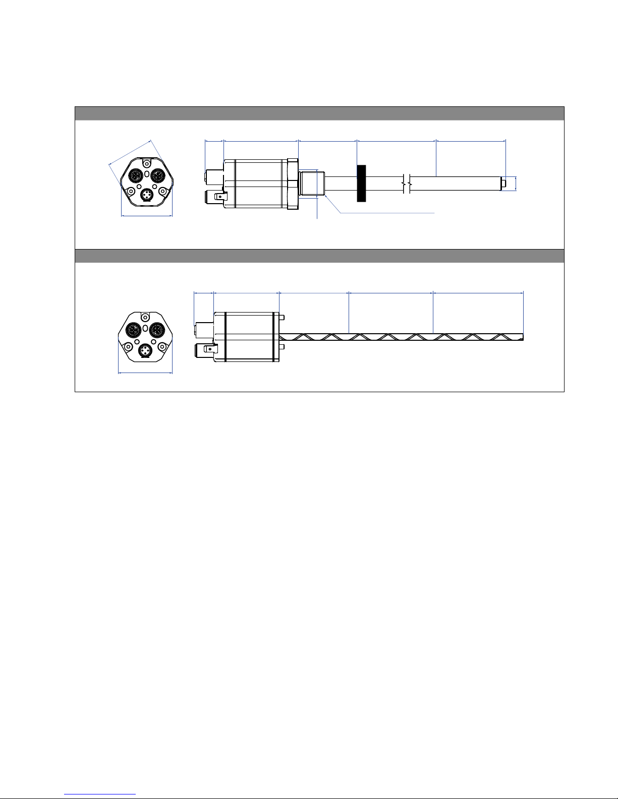
Fig. 7: Temposonics
®
RH5 with ring magnet, part 2
RH5-J-A/-V – RH5 with threaded flange M22×1.5 and Ø 12.7 mm rod (connection type D58)
Port 1 L/A L/A Port 2
A/F 46
48
(1.89)
17
(0.67)
Sensor electronics housing
68
(2.68)
Null zone
51
(2.01)
Stroke length
25…7620
(1…300)
Ø 25.4
(Ø 1)
Threaded flange »J«: M22×1.5-6g
Magnet
Ø 12.7 ±0.13
(Ø 0.5 ±0.01)
Dead zone
73.6
(2.9)
RH5-B-A/-V – RH5 base unit for replacement (connection type D58)
Port 1 L/A L/A Port 2
48
(1.89)
17
(0.67)
Sensor electronics
housing
58
(2.28)
Null zone
61
(2.4)
Stroke length
25…7620
(1…300)
Dead zone
52 / 54 / 57**
(2.05 / 2.13 / 2.24)
* Stroke length 25…1575 (1…62): 52 (2.05) dead zone
Stroke length 1576…5000 (62.05…196.9): 54 (2.13) dead zone
Stroke length 5001…7620 (196.9…300): 57 (2.24) dead zone
Page 12
Temposonics® R-Series V EtherNet/IP™
Operation Manual
I 12 I
Hydraulics sealing
There are two ways to seal the flange contact surface (Fig. 10):
1. A sealing by using an O-ring (e.g. 22.4 × 2.65 mm (0.88 × 0.1 in.),
25.07 × 2.62 mm (0.99 × 0.1 in.)) in a cylinder bottom groove.
2. A sealing by using an O-ring in the undercut.
For threaded flange (¾"-16 UNF-3A):
O-ring 16.4 × 2.2 mm (0.65 × 0.09 in.) (part no. 560 315)
For threaded flange (M18×1.5-6g):
O-ring 15.3 × 2.2 mm (0.60 × 0.09 in.) (part no. 401 133)
For threaded flange (M22×1.5-6g):
O-ring 19.2 × 2.2 mm (0.76 × 0.09 in.) (part no. 561 337)
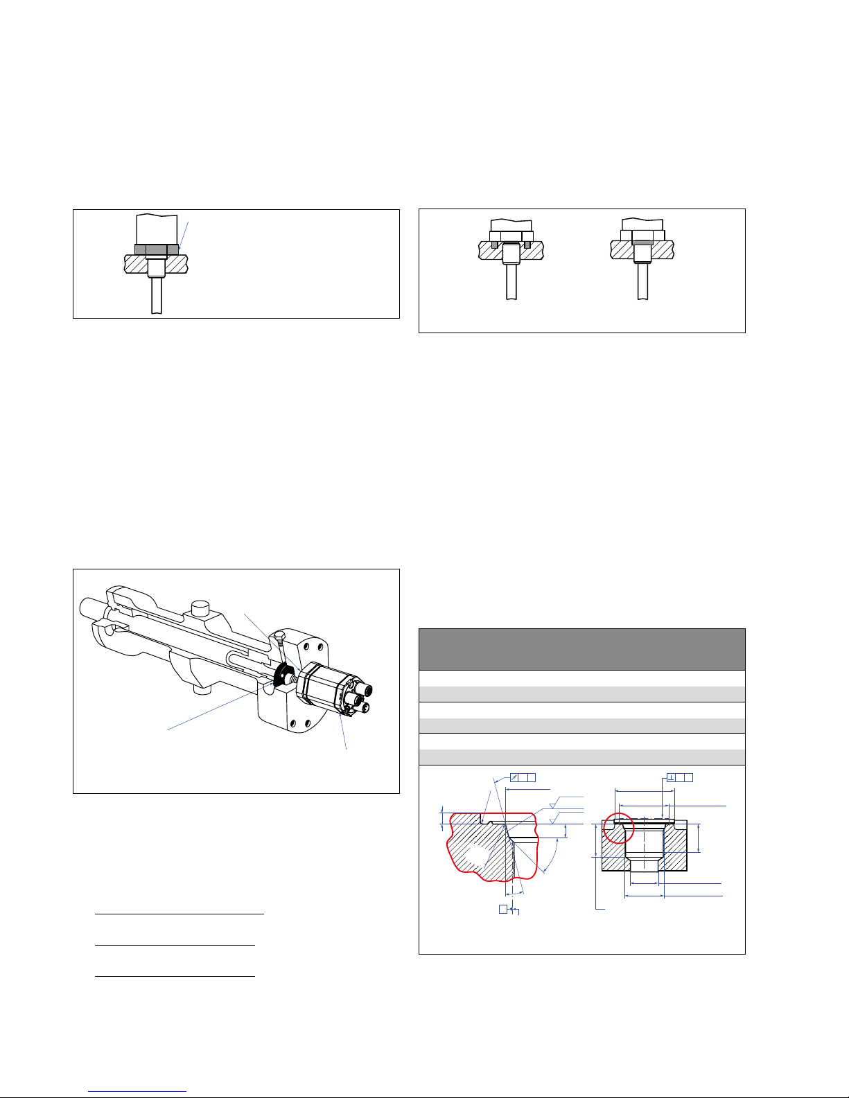
Installation of RH5 with threaded flange
Fix the sensor rod via threaded flange M18×1.5-6g, M22×1.5-6g or
¾"-16 UNF-3A.
In the event of servicing, the sensor rod
with flange remains in the cylinder
Position magnet
Base unit
The sensor electronics housing
with sensing element can be replaced
Installation in a fluid cylinder
The rod-style version has been developed for direct stroke
measurement in a fluid cylinder. Mount the sensor via threaded flange
or a hex nut.
• Mounted on the face of the piston, the position magnet travels
over the rod without touching it and indicates the exact position
through the rod wall – independent of the hydraulic fluid.
• The pressure resistant sensor rod is installed into a bore in the
piston rod.
• The base unit is mounted by means of only two screws. It is the
only part that needs to be replaced if servicing is required, i.e. the
hydraulic circuit remains closed. For more information see chapter
"4.5 Replacement of sensor" on page 16.
Fig. 8: Mounting example of threaded flange
Fig. 9: Sensor in cylinder
3/ RH5-B is for replacement (see Step 4.5)
In the case of threaded flange M18×1.5-6g or M22×1.5-6g, provide
a screw hole based on ISO 6149-1 (Fig. 11). See ISO 6149-1 for further
information.
Controlling design dimensions are in millimeters
Sealing via O-ring
in the flange undercut
Sealing via O-ring
in cylinder end cap groove
Notice for metric threaded flanges
Thread
(d
1
×P)
d2d3d4d
5
+0.1
0
L
1
+0.4
0
L2L3L4Z°
±1°
RH5-M-A/V/M
M18×1.5-6g 55 ≥ 13 24.5 19.8 2.4 28.5 2 26 15°
RH5-M-B
M18×1.5-6g 55 ≥ 16 24.5 19.8 2.4 28.5 2 26 15°
RH5-J-A/V
M22×1.5-6g 55 ≥ 16 27.5 23.8 2.4 28.5 2 26 15°
Ød
5
Ra 3.2
Ra 3.2
Pitch diameter
A
A
Thread
(d1 × P)
Ød
3
(Reference)
A
Ød
2
Ød
4
(Gauging)
This dimension applies when
tap drill cannot pass through
entire boss.
≤ R0.4
R0.3
R0.1
Z°
4
5
°
±
5
°
L
3
L
1
L
2
L
4
A0.1 A0.2
• Note the fastening torque of:
RH5-M /-S / -T: 50 Nm
RH5-J: 125 Nm
• Seat the flange contact surface completely on the cylinder
mounting surface.
• The cylinder manufacturer determines the pressure-resistant
gasket (copper gasket, O-ring, etc.).
• The position magnet should not grind on the sensor rod.
• The piston rod drilling
(RH5-M/S/T-A/V with rod Ø 10 mm: ≥ Ø 13 mm (≥ Ø 0.51 in.);
RH5-M/S/T-A/B with rod Ø 10 mm: ≥ Ø 16 mm (≥ Ø 0.63 in.);
RH5-J-A/V with rod Ø 12.7 mm: ≥ Ø 16 mm (≥ Ø 0.63 in.))
depends on the pressure and piston speed.
• Adhere to the information relating to operating pressure.
• Protect the sensor rod against wear.
Fig. 10: Possibilities of sealing
Fig. 11: Notice for metric threaded flange M18×1.5-6g / M22×1.5-6g based on DIN ISO 6149-1
Fastening torque
RH5-M / -S / -T: 50 Nm
RH5-J: 125 Nm
Page 13

Temposonics® R-Series V EtherNet/IP™
Operation Manual
I 13 I
4.4 Magnet installation
Sensors with stroke lengths ≥ 1 meter (3.3 ft.)
Support horizontally installed sensors with a stroke length from 1 meter
(3.3 ft.) mechanically at the rod end. Without the use of a support, rod
and position magnet may be damaged. A false measurement result is
also possible. Longer rods require evenly distributed mechanical support
over the entire length (e.g. part no. 561 481). Use an U-magnet (Fig. 16)
for measurement.
NOTICE
Mount ring magnets and U-magnets concentrically.
Mount block magnets centrically over the sensor rod or the sensor
profile. The maximum permissible air gap must not be exceeded
(Fig. 13 / Fig. 14).
Take care to mount the primary sensor axis in parallel to the magnet
path in order to avoid damage to the carriage, magnet and sensor
rod.
Controlling design dimensions are in millimeters and measurements in ( ) are in inches
Fig. 12: Typical use of magnets
M4
2
1
8 ±2
(0.31 ±0.08)
Sensor element
Air gap: 3 ±2
(0.12 ±0.08)
Concentric mounting
of block magnet
1
Block magnet
2
Non-magnetic mounting plate
Magnet Typical sensors Benefits
Ring magnets
Rod model
(RH5)
• Rotationally symmetrical
magnetic field
U-magnets
Profile &
rod models
(RP5, RH5)
• The magnet can be lifted off
(RP5)
• Height tolerances can be
compensated
Block magnets
Profile &
rod models
(RP5, RH5)
• The magnet can be lifted off
(RP5)
• Height tolerances can be
compensated
Magnet sliders
Profile models
(RP5)
• The magnet is guided by the
profile
• The distance between the
magnet and the waveguide is
strictly defined
• Easy coupling via the
ball joint
Mounting ring magnets, U-magnets & block magnets
Install the magnet using non-magnetic material for mounting
device, screws, spacers etc.. The magnet must not grind on
the sensor rod. Alignment errors are compensated via the air gap.
• Permissible surface pressure: Max. 40 N/mm
2
(only for ring
magnets and U-magnets)
• Fastening torque for M4 screws: 1 Nm; use washers, if necessary
• Minimum distance between position magnet and any magnetic
material has to be 15 mm (0.6 in.) (Fig. 15).
• If no other option exists and magnetic material is used,
observe the specified dimensions (Fig. 15).
Magnet mounting with magnetic material
When using magnetic material the dimensions of Fig. 15 must
be observed.
A. If the position magnet aligns with the drilled piston rod
B. If the position magnet is set further into the drilled piston rod,
install another non-magnetic spacer (e.g. part no. 400 633) above
the magnet.
Fig. 13: Mounting of U-magnet (part no. 251 416-2 or part no. 201 553)
Fig. 14: Mounting of block magnet (part no. 403
448)
Fig. 15: Installation with magnetic material
U-magnet
Sensor rod
Non-magnetic fixing clip
Magnet
Magnet
1
2
3
A B
Magnetic
material
3
1
Null zone, depends on sensor model (see Fig. 16 / 17)
2
Distance between position magnet and any magnetic material
(≥ 15 mm (≥ 0.6 in.))
3
Non-magnetic spacer (≥ 5 mm (≥ 0.2 in.)) –
Recommendation: 8 mm (0.31 in.)
M4
1
2
Air gap
Concentric mounting
of U-magnet
Part no. 201 553:
3 ±1 (0.12 ±0.04)
Part no. 251 416-2:
1.75 ±1 (0.07 ±0.04)
1
U-magnet
2
Non-magnetic mounting plate and fasteners
Fig. 16: Example of sensor support (part no. 561 481)
Page 14

Temposonics® R-Series V EtherNet/IP™
Operation Manual
I 14 I
Start- and end positions of the position magnets
Consider the start and end positions of the position magnets during the installation. To ensure that the entire stroke length is electrically usable,
the position magnet must be mechanically mounted as follows.
RP5 with U-magnet
Reference edge of mounting
Sensor electronics housing
Start position
28 (1.1)
End position
66 / 71* (2.6 / 2.8*)
* Stroke length > 5000 mm (196.9 in.)
RP5 with magnet slider “S”, “N”, “V”, “G”
Sensor electronics housing
Reference edge of mounting
Start position
12 (0.47)
End position
82 / 87* (3.23 / 3.43*)
* Stroke length > 5000 mm (196.9 in.)
RP5 with block magnet
Reference edge of mounting
Sensor electronics housing
* Stroke length > 5000 mm (196.9 in.)
End position
68.5 / 73.5* (2.7 / 2.9*)
Start position
25.5 (1)
RH5 with ring magnet / U-magnet
Sensor electronics housing
Reference edge of mounting
Start position
51 (2.01)
End position
63.5 / 66* (2.5 / 2.6*)
* Stroke length > 5000 mm (196.9 in.)
RH5 with block magnet
Sensor electronics housing
Reference edge of mounting
Start position
48.5 (1.91)
End position
66 / 68.5* (2.6 / 2.7*)
* Stroke length > 5000 mm (196.9 in.)
Fig. 17: Start- & end positions of magnets, part 1
Controlling design dimensions are in millimeters and measurements in ( ) are in inches
Fig. 18: Start- & end positions of magnets, part 2
NOTICE
On all sensors, use only the active measurement stroke, which is
between the start and end positions. The magnet may move beyond
these positions.
Page 15

Temposonics® R-Series V EtherNet/IP™
Operation Manual
I 15 I
NOTICE
Use magnets of the same type (e.g. 2 ring magnets ) for
multi-position measurement.
The minimum allowed distance between magnets (i.e. front face of
one to the front face of the next one) is 75 mm (3 in.). for multiposition measurement.*
*/ Contact MTS Sensors if you need a magnet distance, which is smaller than 75 mm (3 in.).
Controlling design dimensions are in millimeters and measurements in ( ) are in inches
Multi-position measurement
The minimum distance between the magnets is 75 mm (3 in.).
RP5 with U-magnet
≥ 75 (≥ 3)
RP5 with magnet sliders
≥ 75 (≥ 3)
RP5 with block magnets
≥ 75 (≥ 3)
RH5 with ring magnets / U-magnets
≥ 75 (≥ 3)
RH5 with block magnets
≥ 75 (≥ 3)
Fig. 19: Minimum distance for multi-position measurement
Page 16

Temposonics® R-Series V EtherNet/IP™
Operation Manual
I 16 I
Fig. 20: Replacement of the base unit (e.g. RH5 sensor), part 1
NOTICE
• Secure the base unit screws, e.g. using Loctite 243, before
re-installing.
NOTICE
In the event the R-Series V is replacing the R-Series 2004 the plastic
tube must also be remove.
Base unit
Sensor electronics housing
Plastic tube with inner
sensor element
1. Loosen the screws.
3 × socket head screw
M4 (A/F 2.5)
2. Pull out the base unit.
4.5 Replacement of sensor
The base unit of the sensor models RH (RH5-B) is replaceable as
shown in Fig. 20 and Fig. 21. The sensor can be replaced without
interrupting the hydraulic circuit.
3. Insert the new base unit.
Mount the ground lug on a screw.
Tighten the screws.
Fastening torque
1.3 Nm
Fig. 21: Replacement of the base unit (e.g. RH5 sensor), part 2
Page 17

Temposonics® R-Series V EtherNet/IP™
Operation Manual
I 17 I
4.6 Electrical connections
Placement of installation and cabling have decisive influence on
the sensor‘s electromagnetic compatibility (EMC). Hence correct
installation of this active electronic system and the EMC of the entire
system must be ensured by using suitable metal connectors, shielded
cables and grounding. Overvoltages or faulty connections can damage
its electronics despite protection against wrong polarity.
Instructions for connection
• Use low-resistant twisted pair and shielded cables. Connect
the shield to ground externally via the controller equipment.
• Keep control and signal cables separate from power cables and
sufficiently far away from motor cables, frequency inverters,
valve lines, relays, etc..
• Use only connectors with metal housing and connect the shielding
to the connector housing.
• Keep the connection surface at both shielding ends as large
as possible. Connect the cable clamps to function as a ground.
• Keep all non-shielded leads as short as possible.
• Keep the earth connection as short as possible with a large
cross section. Avoid ground loops.
• With potential differences between machine and electronics earth
connections, no compensating currents are allowed to flow across
the cable shielding.
Recommendation:
Install potential compensating leads with large cross section,
or use cables with separate double shielding, and connect only
one end of the shield.
• Use only stabilized power supplies in compliance with the
specified electrical ratings.
Grounding of profile and rod sensors
Connect the sensor electronics housing to machine ground. Ground
sensor types RP and RH via ground lug as shown in Fig. 22. In
addition you can ground the sensor type RH via thread.
Connector wiring
Connect the sensor directly to the control system, indicator or other
evaluating systems as follows:
Fig. 22: Grounding via ground lug (e.g. RP5)
Fig. 23: Location of connections (e.g. D58 connector wiring)
NOTICE
1. Do not mount the sensors in the area of strong magnetic or
electric noise fields.
2. Never connect / disconnect the sensor when voltage is applied.
Port 1 L/A L/A Port 2
Port 2Port 1
Operating voltage
D56
Signal
Port 1 – M12 female
connector (D-coded)
Pin Function
2
3
4
5
1
View on sensor
1 Tx (+)
2 Rx (+)
3 Tx (−)
4 Rx (−)
5 Not connected
Port 2 – M12 female
connector (D-coded)
Pin Function
2
3
4
5
1
View on sensor
1 Tx (+)
2 Rx (+)
3 Tx (−)
4 Rx (−)
5 Not connected
Power supply
M8 male connector Pin Function
2
4
1
3
View on sensor
1 12…30 VDC (±20 %)
2 Not connected
3 DC Ground (0 V)
4 Not connected
Fig. 24: Connector wiring D56
Page 18

Temposonics® R-Series V EtherNet/IP™
Operation Manual
I 18 I
D58
Signal
Port 1 – M12 female
connector (D-coded)
Pin Function
2
3
4
5
1
View on sensor
1 Tx (+)
2 Rx (+)
3 Tx (−)
4 Rx (−)
5 Not connected
Port 2 – M12 female
connector (D-coded)
Pin Function
2
3
4
5
1
View on sensor
1 Tx (+)
2 Rx (+)
3 Tx (−)
4 Rx (−)
5 Not connected
Power supply
M12 male connector
(A-coded)
Pin Function
1
2
4
3
View on sensor
1 12…30 VDC (±20 %)
2 Not connected
3 DC Ground (0 V)
4 Not connected
Fig. 25: Connector wiring D58
Page 19

Temposonics® R-Series V EtherNet/IP™
Operation Manual
I 19 I
4.7 Frequently ordered accessories
Position magnets
M5
20
(0.79)
43
(1.69)
14
(0.55)
22.1 (0.87)
40 (1.57)
18°
25.3
(1)
40 (1.58)
18°
57 (2.24)
14
(0.55)
13.3 (0.51)
25.3 (1)
49 (1.93)
M5
17.2 (0.67)
24
(0.94)
18°
20
(0.79)
43
(1.69)
40 (1.57)
M5
25.3
(1)
18°
40 (1.57)
25.3
(1)
20
(0.79)
42
(1.65)
15.2
(0.6)
16.6 (0.63)
M5
Magnet slider S, joint at top
Part no. 252 182
Magnet slider V, joint at front
Part no. 252 184
Magnet slider N
longer ball-joint arm
Part no. 252 183
Magnet slider G, backlash free
Part no. 253 421
Material: GRP, magnet hard ferrite
Weight: Approx. 35 g
Operating temperature:
−40…+75 °C (−40…+167 °F)
Material: GRP, magnet hard ferrite
Weight: Approx. 35 g
Operating temperature:
−40…+75 °C (−40…+167 °F)
Material: GRP, magnet hard ferrite
Weight: Approx. 35 g
Operating temperature:
−40…+75 °C (−40…+167 °F)
Material: GRP, magnet hard ferrite
Weight: Approx. 25 g
Operating temperature:
−40…+75 °C (−40…+167 °F)
Position magnets
Ø 32.8
(Ø 1.29)
Ø 23.8
(Ø 0.94)
Ø 13.5
(Ø 0.53)
Ø 4.3
(Ø 0.17)
60°
140°
3
(0.12)
7.9
(0.31)
Ø 4.5 (Ø 0.18)
Ø 63.5
(Ø 2.5)
Ø 42
(Ø 1.65)
Ø 16
(Ø 0.63)
97°
30°
9.5
(0.37)
Ø 32.8
(Ø 1.29)
Ø 23.8
(Ø 0.94)
Ø 13.5
(Ø 0.53)
Ø 4.3
(Ø
0.17)
7.9
(0.31)
Ø 25.4
(Ø 1)
Ø 13.5
(
Ø
0.53)
7.9
(0.31)
U-magnet OD33
Part no. 251 416-2
U-magnet OD63.5
Part no. 201 553
Ring magnet OD33
Part no. 201 542-2
Ring magnet OD25.4
Part no. 400 533
Material: PA ferrite GF20
Weight: Approx. 11 g
Surface pressure: Max. 40 N/mm
2
Fastening torque for M4 screws: 1 Nm
Operating temperature:
−40…+105 °C (−40…+221 °F)
Material: PA 66-GF30,
magnets compound- lled
Weight: Approx. 26 g
Surface pressure: 20 N/mm
2
Fastening torque for M4 screws: 1 Nm
Operating temperature:
−40…+75 °C (−40…+167 °F)
Material: PA ferrite GF20
Weight: Approx. 14 g
Surface pressure: Max. 40 N/mm
2
Fastening torque for M4 screws: 1 Nm
Operating temperature:
−40…+105 °C (−40…+221 °F)
Material: PA ferrite
Weight: Approx. 10 g
Surface pressure: Max. 40 N/mm
2
Operating temperature:
−40…+105 °C (−40…+221 °F)
Position magnets Magnet spacer O-ring
Ø 19.8
(Ø 0.78)
Ø 30.5
(Ø 1.2)
7.6
(0.3)
19.5 (0.77)
1.5
(0.06)
33 (1.3)
14
(0.55)
20.5
(0.81)
14.9 (0.59)
8 ± 2 (0.31 ± 0.08)
Distance to sensor element
Ø 4.3
(Ø 0.17)
Ø 14.3
(Ø 0.56)
Ø 23.8
(Ø 0.94)
Ø 31.8
(Ø 1.25)
Ø 4.3
(Ø 0.17)
3.2
(0.13)
Ø 14.3
Ø 23.8
Ø 31.8
Ø 4.3
3.2
Ø 15.3
(Ø 0.6)
Ø 2.2
(Ø 0.09)
Ring magnet
Part no. 402 316
Block magnet L
Part no. 403 448
Magnet spacer
Part no. 400 633
O-ring for threaded fl ange
M18×1.5-6g
Part no. 401 133
Material: PA ferrite coated
Weight: Approx. 13 g
Surface pressure: Max. 20 N/mm
2
Operating temperature:
−40…+100 °C (−40…+212 °F)
Material: Hard ferrite
Weight: Approx. 20 g
Fastening torque for M4 screws: 1 Nm
Operating temperature:
−40…+75 °C (−40…+167 °F)
This magnet may in uence the sensor
performance speci cations for some
applications.
Material: Aluminum
Weight: Approx. 5 g
Surface pressure: Max. 20 N/mm
2
Fastening torque for M4 screws: 1 Nm
Material: Fluoroelastomer
Durometer: 75 ± 5 Shore A
Operating temperature:
−40…+204 °C (−40…+400 °F)
– Additional options available in our Accessories Guide
551 444
Controlling design dimensions are in millimeters and measurements in ( ) are in inches
Page 20

Temposonics® R-Series V EtherNet/IP™
Operation Manual
I 20 I
4/ Follow the manufacturer‘s mounting instructions
Controlling design dimensions are in millimeters and measurements in ( ) are in inches
O-rings Mounting hardware
Ø 16.4
(Ø 0.65)
Ø 2.2
(Ø 0.09)
Ø 19.3
(Ø 0.76)
Ø 2.2
(Ø 0.09)
M18×1.5-6g
A/F 27
8.7
(0.34)
¾"-16 UNF-3A
A/F 28
11
(0.43)
O-ring for threaded fl ange
¾"-16 UNF-3A
Part no. 560 315
O-ring for threaded fl ange
M22×1.5-6g
Part no. 561 337
Hex jam nut M18×1.5-6g
Part no. 500 018
Hex jam nut ¾"-16 UNF-3A
Part no. 500 015
Material: Fluoroelastomer
Durometer: 75 ± 5 Shore A
Operating temperature:
−40…+204 °C (−40…+400 °F)
Material: FPM
Durometer: 75 Shore A
Operating temperature:
−20…+200 °C (−6…+392 °F)
Material: Steel, zinc, plated Material: Zinc plated with nylon insert
Mounting hardware Accessory for M12 cable connector
4 Holes
Ø 5.3 (Ø 0.21)
28 (1.1)
9 (0.35)
50 (1.97)
2 (0.08)
68 (2.68)
9 (0.35)
Mounting clamp width:
14.6 (0.57)
4
(0.16)
11.5
(0.45)
4.5
(1.8)
8
(0.31)
M5 thread
20 (0.79)
60 (2.36)
16 (0.63)
12 (0.47)
3.2 (0.13)
Ø 3.2 (Ø 0.13)
M3 fastening screws (6×)
M12
Ø 16
(Ø 0.63)
16
(0.63)
6
(0.24)
Mounting clamp
Part no. 400 802
T-nut
Part no. 401 602
Fixing clip for rod with Ø 10 mm
Part no. 561 481
M12 connector end cap
Part no. 370 537
Material: Stainless steel (AISI 304) Fastening torque for M5 screw: 4.5 Nm Application: Used to secure sensor
rods (Ø 10 mm (Ø 0.39 in.)) when
using an U-magnet or block magnet
Material: Brass, non-magnetic
Female connectors M12 should be
covered by this protective cap
Material: Brass nickel-plated
Ingress protection: IP67 (correctly tted)
Fastening torque: 0.39…0.49 Nm
Cable connectors
4
Cables
52
(2.05)
Ø 19.5
(Ø 0.77)
53
(2.09)
Ø 20
(Ø 0.79
)
43
(1.7)
Ø 12
(
Ø
0.47)
M8
M12
Ø 16
(Ø 0.63)
16
(0.63)
6
(0.24)
M12 D-coded male connector
(4 pin), straight
Part no. 370 523
M12 A-coded female connector
(5 pin), straight
Part no. 370 677
M8 female connector (4 pin), straight
Part no. 370 504
M12 connector end cap
Part no. 370 537
Material: Zinc nickel-plated
Termination: Insulation-displacement
Cable Ø: 5.5…7.2 mm (0.2…0.28 in.)
Wire: 24 AWG – 22 AWG
Operating temperature:
−25…+85 °C (−13…+185 °F)
Ingress protection: IP65 / IP67
(correctly tted)
Fastening torque: 0.6 Nm
Material: GD-Zn, Ni
Termination: Screw
Contact insert: CuZn
Cable Ø: 4…8 mm (0.16…0.31 in.)
Wire: 1.5 mm²
Operating temperature:
−30…+85 °C (−22…+185 °F)
Ingress protection: IP67 (correctly tted)
Fastening torque: 0.6 Nm
Material: CuZn nickel plated
Termination: Solder
Cable Ø: 3.5…5 mm (0.14…0.28 in.)
Wire: 0.25 mm
2
Operating temperature:
−40…+85 °C (−40…+185 °F)
Ingress protection: IP67 (correctly tted)
Fastening torque: 0.5 Nm
Female connectors M12 should be
covered by this protective cap
Material: Brass nickel-plated
Ingress protection: IP67 (correctly tted)
Fastening torque: 0.39…0.49 Nm
Page 21

Temposonics® R-Series V EtherNet/IP™
Operation Manual
I 21 I
Cables
PUR cable
Part no. 530 125
PVC cable
Part no. 530 108
Cable with M12 D-coded male
connector (4 pin), straight – M12
D-coded, male connector (4 pin),
straight
Part no. 530 064
Cable with M12 D-coded male
connector (4 pin), straight – RJ45
male connector, straight
Part no. 530 065
Material: PUR jacket; green
Features: Cat 5, highly exible
Cable Ø: 6.5 mm (0.26 in.)
Cross section: 2 × 2 × 0.35 mm
2
(22/7 AWG)
Operating temperature:
−20…+60 °C (−4…+140 °F)
Material: PVC jacket; gray
Features: Shielded, exible
Cable Ø: 4.9 mm (0.19 in.)
Cross section: 3 × 0.34 mm²
Operating temperature:
−30…+80 °C (−22…+176 °F)
Material: PUR jacket; green
Features: Cat 5e
Cable length: 5 m (16.4 ft)
Cable Ø: 6.5 mm (0.26 in.)
Ingress protection: IP65, IP67, IP68
(correctly tted)
Operating temperature:
−30…+70 °C (−22…+158 °F)
Material: PUR jacket; green
Features: Cat 5e
Cable length: 5 m (16.4 ft)
Cable Ø: 6.5 mm (0.26 in.)
Ingress protection M12 connector:
IP67 (correctly tted)
Ingress protection RJ45 connector:
IP20 (correctly tted)
Operating temperature:
−30…+70 °C (−22…+158 °F)
Cables Programming kit
Cable with M8 female connector
(4 pin), straight – pigtail
Part no. 530 066 (5 m (16.4 ft.))
Part no. 530 096 (10 m (32.8 ft.))
Part no. 530 093 (15 m (49.2 ft.))
TempoLink smart assistant for
Temposonics® R-Series V
Part no. TL-1-0-EM12
Material: PUR jacket; gray
Features: Shielded
Cable Ø: 8 mm (0.3 in.)
Operating temperature:
−40…+90 °C (−40…+194 °F)
• Connect wirelessly via Wi-Fi enabled
device or via USB with the diagnostic
tool
• Simple connectivity to the sensor
via 24 VDC power line
• User friendly interface for mobile
devices and desktop computers
• Rugged ABS plastic construction
for the industrial environment
• See product brief “TempoLink
smart assistant” (document part no.:
551976) for further information
Controlling design dimensions are in millimeters and measurements in ( ) are in inches
Manuals & Software available at:
www.mtssensors.com
Page 22

Temposonics® R-Series V EtherNet/IP™
Operation Manual
I 22 I
5. Operation
5.1 LED Status
NOTICE
Observe during commissioning
1. Before initial switch-on, check carefully if the sensor has
been connected correctly.
2. Position the magnet in the measuring range of the sensor
during first commissioning and after replacement of the
magnet.
3. Ensure that the sensor control system cannot react in an
uncontrolled way when switching on.
4. Ensure that the sensor is ready and in operation mode after
switching on. The connection indicator LEDs will show green
for on and red for off.
EtherNet/IP™ LED status
Port 1 L/A L/A Port 2
Connection indicator
Port 1 Port 2
Connection indicator
Module status LED
Port 1 L/A L/A Port 2
Green Red Information
ON OFF
IP address con gured
Flashing OFF IP address not con gured
OFF Flashing Duplicate of IP address recognized
Network status LED
Port 1 L/A L/A Port 2
Green Red Information
ON OFF
Connection established
Flashing OFF No connection
OFF ON Unrecoverable error
OFF Flashing Recoverable error
EtherNet/IP™ LED status
Port 1 L/A L/A Port 2
Connection indicator
Port 1 Port 2
Connection indicator
Module status LED
Port 1 L/A L/A Port 2
Green Red Information
ON
OFF
IP address con gured
Flashing
OFF IP address not con gured
OFF Flashing Duplicate of IP address recognized
Network status LED
Port 1 L/A L/A Port 2
Green Red Information
ON OFF
Connection established
Flashing OFF No connection
OFF ON Unrecoverable error
OFF Flashing Recoverable error
Port 1 L/A (IN)
Port 1 L/A L/A Port 2
Green Red Information
ON OFF
LINK activity on port 1
Flickers OFF Data transfer on port 1
OFF ON No magnet / Wrong quantity of magnets
Port 2 L/A (OUT)
Port 1 L/A L/A Port 2
Green Red Information
ON OFF LINK activity on port 2
Flickers OFF
Data transfer on port 2
Page 23

Temposonics® R-Series V EtherNet/IP™
Operation Manual
I 23 I
NOTICE
Physically connect the sensor to your network, but do not apply
power to the sensor. You will be instructed when it is time to power
the sensor.
6. Programming and conguration
6.1 IP address Conguration
An example of conguring an MTS EtherNet/IP™ sensor will be
shown using an Allen-Bradley CompactLogix L35E controller, and
the RSLogix 5000 software from Rockwell. This example is written
with the understanding that the customer already has an EtherNet/
IP™ capable controller, and a working EtherNet/IP™ network.
The procedure to incorporate an MTS EtherNet/IP™ sensor into a
network is shown in the following 3 steps. Step 1 describes setting
the IP address of the sensor and step 2 installing the MTS EtherNet/
IP™ EDS le (download at www.mtssensors.com). To utilize the
EDS le with the add-on prole feature, the RSLogix 5000 software
must be version 20 or later. By using the EDS add-on prole, the
sensor parameters and conguration data are loaded automatically
to complete steps 3.1 and 3.2. If not installing the sensor EDS le,
or if using an earlier version of the RSLogix 5000 software, chapters
7.3 through 7.5 describe how to manually load the sensor parameter
data. Also, if needed later, the descriptions in step 3.2 can help when
reviewing the sensor parameter data and for making any changes.
NOTICE
1. Choose an IP address that is not being used on your network or
subnetwork.
2. After the IP address is assigned to the sensor, record the IP
address and have it available as you will need it to communicate
with the sensor.
6.2 Setting the IP address of the sensor
Each sensor comes from the factory with DHCP mode active, and a
unique MAC ID (see sensor label). This allows you to communicate
with the sensor in order to congure the sensor for your network.
Before you can use a sensor on your network you must rst assign
it an static, unused IP address on your network. In the following
example we will use Rockwell’s BOOTP/DHCP Server program to
assign an IP address to the sensor.
6.2.1 Open the BOOTP/DHCP Server software.
The ‘BOOTP/DHCP Server’ window opens.
6.2.2 To add your sensor to the ‘Relation List’, click the New button
in the ‘Relation List’ pane.
The ‘New Entry’ window opens.
Fig. 26: Create new relation list entry
Fig. 27: Enter MAC ID and unique IP address
Fig. 28: Populated relation list
6.2.3 In the ‘New Entry’ window, enter the MAC ID (see sensor label).
Enter a unique IP address you will use for the sensor, record
the IP address and click OK.
6.2.4 Verify that your unique IP address and MAC ID appear in the
‘Relation List’ window. If the relation list window does not
contain both MAC ID and IP address, repeat steps 6.2.2 to 6.2.4.
Otherwise, continue to step 6.2.5.
Page 24

Temposonics® R-Series V EtherNet/IP™
Operation Manual
I 24 I
NOTICE
Step 6.2.7 will make your sensors unique IP address static. It will
disable BOOTP and DHCP, and the IP address will be stored in the
EEPROM of the sensor.
Fig. 29: Request History shows MAC ID and IP address
Fig. 30: Sensor shows the static IP address
6.2.5 Apply power to the sensor. The sensor should take around 10 to
15 seconds to begin to broadcast its MAC ID.
6.2.6 Verify that your IP address and MAC ID appear in the ‘Request
History’ box.
6.2.7 Click to select your sensor in the ‘Relation List’ box and click the
disable BOOTP/DHCP button.
6.2.8 The ‘Status’ message at the bottom of the window will read
“Command Successful” if the disable command was successful.
The sensor is now assigned a static IP address. If needed,
repeat step 6.2.7 until the disable command is successful.
6.2.9 Exit the BOOT/DHCP Server software. If installing the MTS
EtherNet/IP™ EDS le (download at www.mtssensors.com)
continue with chapter 7.1. To utilize the EDS le, the RSLogix
5000 software must be version 20 or later.
If not installing the sensor EDS le, or if using an earlier version
of the RSLogix 5000 software, the sensor parameter data must
be manually loaded. In that case, continue with Steps 2 and 3.
Page 25

Temposonics® R-Series V EtherNet/IP™
Operation Manual
I 25 I
7. Integration in RSLogix 5000
7.1 Install the MTS EtherNet/IP™ EDS file
The EDS file for the R-Series V EtherNet/IP™ sensor is available at
www.mtssensors.com.
It provides full backwards compatibility to the previous generation of
R-Series EtherNet/IP™ sensors.
7.1.1 Open the RSLogix 5000 software interface.
7.1.2 Click the Tools menu and select “EDS Hardware Installation
Tool”.
Fig. 31: Select the “EDS Hardware Installation Tool”
Fig. 32: EDS wizard launch screen
Fig. 33: Register an EDS le
7.1.3 The ‘EDS Wizard’ window opens, click Next, in the ‘Options’
window select Register an EDS le(s) and click “Next”.
Page 26

Temposonics® R-Series V EtherNet/IP™
Operation Manual
I 26 I
Fig. 34: Enter the path to the EDS le
Fig. 35: Conrmation of path to the EDS le
Fig. 36: Conrmation of EDS le origin
Fig. 37: EDS Installation Complete
7.1.4 The ‘Registration’ window opens, click Browse and select the
EDS le provided either with the sensor or downloaded from
the MTS website. Click “Next”.
7.1.5 If the installation completed successfully, the ‘EDS File
installation test results’ window displays. Click “Next”.
7.1.6 The ‘Final Task Summary’ window opens, click “Next”.
7.1.7 Click “Finish”.
Page 27

Temposonics® R-Series V EtherNet/IP™
Operation Manual
I 27 I
7.2.1 After completing the EDS wizard, return to the main window
of RSLogix 5000. In the controller organizer sidebar, expand
the I/O Conguration tree and right-click your network. Select
“New Module”.
7.2.2 In the Select Module Type window, choose “R-Series EtherNet/
IP” and click “Create”.
7.2.3 In the New Module window, enter a name in the ‘Name’ eld,
select the IP address radio button and enter the static IP
address that is assigned to the sensor. Click “OK” and close the
new module window.
7.2 Add sensor to I/O configuration using EDS file
Fig. 38: Add a new module to the RSLogix 5000 IO tree
Fig. 39: Create new moduletree
Fig. 40: Conrm the new module settings
Page 28

Temposonics® R-Series V EtherNet/IP™
Operation Manual
I 28 I
7.2.4 Verify that the new sensor is listed in the I/O Conguration tree.
The MTS EtherNet/IP™ sensor is now added to the network and
connected, ready to use.
NOTICE
If the sensor is disconnected, a yellow warning sign (shown below)
will appear over the module icon.
Before you begin, you will need the sensors static IP address you
recorded in from step 6.2.7.
7.3.1 Open the RSLogix 500 software interface.
7.3.2 Open the controllers’ directory tree. Click I/O conguration,
then right click your network. Select “New Module”. The “Select
Module” window opens.
7.3.3 In the “Select Module” window, select “Generic Ethernet
Module” and press “OK”. The “New Module” window opens.
Fig. 41: New module on the network
Fig. 42: Add a new module to the RSLogix 5000 IO tree
Fig. 43: Add a new Generic moduletree
7.3 Add sensor to I/O configuration without using EDS file
Page 29

Temposonics® R-Series V EtherNet/IP™
Operation Manual
I 29 I
7.3.4 In the ‘New Module’ window (Fig. 44) perform step 7.3.4.1 –
7.3.4.4 to congure the new generic ethernet module to the
R-Series EtherNet/IP™ sensor.
7.3.4.1 In the “Name” eld enter the “Sensor Name” as described in
the “I/O Conguration tree” (it might be benecial to include
reference to the device ID).
7.3.4.2 In the “Comm Format” eld, to “Set the Comm Format” to
select Input Data - DINT - Run/Program from the drop down
menu
7.3.4.3 In the “Address / Host Name” eld, select the IP address
option and enter the static IP address you assigned to the
sensor in chapter 6.1.
7.3.4.4 To set the “Connection Parameters” enter the following
connection parameters eld information:
NOTICE
Enter the “Connection Parameters” and “Comm Format” exactly in
the following order in step 7.3.4.1 – 7.3.4.4, otherwise your sensor
may not function properly.
NOTICE
RPI limitations are:
• 2 ms up to 4800 mm stroke
• 4 ms up to 7620 mm stroke
Select the open module properties check box and click “OK”. The
“Module Properties” window opens.
7.3.4.1
7.3.4.2
7.3.4.3
7.3.4.4
7.4 Set Module RPI
7.4.1 Click the “Connection” tab. Set the “Requested Packet Interval”
(RPI) value and press “OK”. (The default value is 10milliseconds,
but the sensor is capable of a RPI as low as 2milliseconds).
Fig. 44: New Module window
Fig. 45: New module properties
Fig. 46: New generic module has been added to the network
7.5 Verify Generic EtherNet Module
7.5.1 Verify that the new sensor is listed on the I/O conguration tree.
Name Instance eld Size eld
Input assembly 101 50
Output assembly 100 –
Confguration assembly 10 20
Page 30

Temposonics® R-Series V EtherNet/IP™
Operation Manual
I 30 I
7.6 Verify Generic Ethernet Module
7.6.1 In the ‘I/O conguration tree’, click to open the ‘Controller Tags’ directory. The controller tag table displays in the left pane (Fig. 47). The
description column elds will be blank by default.
Fig. 47: Device control tags
7.6.2 In the ‘Style’ column, change the eld data default from hex to decimal.
Page 31

Temposonics® R-Series V EtherNet/IP™
Operation Manual
I 31 I
Name Description Values Description
Data Byte [0]
Data format
0 4 bytes signed position, 4 bytes signed velocity (repeats for each magnet)
1 4 bytes signed position (repeats for each magnet)
2 4 bytes signed velocity (repeats for each magnet)
3
(default value)
First 4 bytes are status. Then repeating for each magnet: 4 bytes signed position, 4 bytes signed velocity.
The 4 status bytes are dened as follows:
• Lower byte (bits 0 – 7) = Status
• Bit 0 = Magnet missing (0 = magnet not missing, 1 = magnet missing)
• Bit 1 = CPU Watchdog (0 = not triggered, 1 = triggered)
• Bits 2 – 7 = Not used
• Middle 2 bytes (bits 8 – 23) = Unused
• Upper byte (bits 24 – 31) = Number of magnets found on the sensor
Data Byte [1]
Resolution
0 0.001 mm (default value, also the same as value = 1)
1 0.001 mm
2 0.002 mm
5 0.005 mm
10 0.010 mm
20 0.020 mm
50 0.050 mm
100 0.100 mm
200 0.200 mm
500 0.500 mm
Data Byte [2]
Measuring direction
0 Forward (counts increase as you move away from the electronics) (default value)
1 Reverse (counts decrease as you move away from the electronics)
Data Byte [3]
Number of magnets
0
Used for missing magnet detection purposes only. If the ‘Value’ = 0, the sensor will determine how many magnets are on the
sensor at startup. It will use the determined number of magnets to determine missing magnet status. The missing magnet
status is reported in the status attribute of the Position Sensor object and through the LEDs in the connector ange.
Data Byte [4]
Velocity window size
1…1000
The number of cycles that is used to calculate the velocity. The larger the number of cycles the more resolute the velocity
becomes, but the slower the sensor is to respond to a change in velocity (default value: 1, no smoothing).
Data Byte [5]
Number of averages
0…100 A simple moving average that can be used to lter the position data in noisy environments (default value: 1, no averaging).
7.6.3 Locate Data Byte [0] through [5] In the ‘Name’ column. In the ‘Description’ column, enter the following Data Byte eld information.
Page 32

Temposonics® R-Series V EtherNet/IP™
Operation Manual
I 32 I
7.7 Controller tags input data
The following illustrates an example of 'Controller Tags' information based on the factory default conguration:
Fig. 48: Controller tags
'Controller Tags' information Examples based on the factory default conguration are as follows:
7.8.1 Run/Idle Header
Data[0] is always the Run/Idle header. This is not required by the EtherNet/IP™ standard, but it is highly recommended. It can be used by the end
user to determine if the system is in Run or Idle mode.
7.8.2 Magnet Data
The remaining data is laid out according to the data format selected in the conguration. The screenshot on page 32 in section 7.8 shows the
position data for magnet 1 in Data[1], and the velocity for magnet 1 in Data[2].
Magnet data – Position
The position data for magnet one in this example is 100887. This number multiplied by the resolution
(default = 0.001 mm) gives you your position.
Position = 100887 × 0.001 mm = 100.887 mm
Magnet data – Velocity
The velocity data for magnet one in this example is 60113. The velocity resolution is always 0.001 mm.
Velocity = 60113 × 0.001 mm = 60.113 mm
7.8.3 Configuration complete
The MTS EtherNet/IP™ sensor is now added to the network, connected, and ready to use.
Page 33

Temposonics® R-Series V EtherNet/IP™
Operation Manual
I 33 I
8.1 Error conditions, troubleshooting
See chapter "5. Operation" on page 22.
8.2 Maintenance
The sensor is maintenance-free.
8.3 Repair
Repairs of the sensor may be performed only by MTS Sensors or
a repair facility explicitly authorized by MTS Sensors.
8. Maintenance and troubleshooting
9. Removal from service / dismantling
The product contains electronic components and must be disposed
of in accordance with the local regulations.
8.4 List of spare parts
No spare parts are available for this sensor.
8.5 Transport and storage
The conditions of transport and storage of the sensor match the
operating conditions mentioned in this document.
Page 34

10. Technical data
9.1 Technical data Temposonics® R-Series V RP
Output
Interface EtherNet/IP™
Data protocol Encoder CIP device prole with CIP Sync and DLR capabilities
Data transmission rate 100 MBit/s (maximum)
Measured value Position, velocity / option: Simultaneous multi-position and multi-velocity measurements up to 20 magnets
Measurement parameters
Resolution: Position 1…500 µm (selectable)
Cycle time
Stroke length up to 2000 mm up to 4800 mm up to 7620 mm
Cycle time 1.0 ms 2.0 ms 3.0 ms
Linearity deviation
5
Stroke length up to 500 mm greater than 500 mm
Linearity deviation ≤ ±50 µm < 0.01 % F.S.
Repeatability < ±0.001 % F.S. (minimum ±2.5 μm) typical
Hysteresis < 4 µm, typical 2 µm
Operating conditions
Operating temperature −40…+85 °C (−40…+185 °F)
Humidity 90 % relative humidity, no condensation
Ingress protection IP65 (connectors correctly fitted)
Shock test 150 g / 11 ms, IEC standard 60068-2-27
Vibration test 30 g / 10…2000 Hz, IEC standard 60068-2-6 (excluding resonant frequencies)
EMC test Electromagnetic emission according to EN 61000-6-3
Electromagnetic immunity according to EN 61000-6-2
The sensor meets the requirements of the EC directives and is marked with
Magnet movement velocity Magnet slider: Max. 10 m/s; U-magnet: Any; block magnet: Any
Design / Material
Sensor electronics housing Aluminum (painted), zinc die cast
Sensor profile Aluminum
Stroke length 25…6350 mm (1…250 in.)
Mechanical mounting
Mounting position Any
Mounting instruction
Please consult the technical drawings on page 9
Electrical connection
Connection type
2 × M12 female connectors (5 pin), 1 × M8 male connector (4 pin),
2 × M12 female connectors (5 pin), 1 × M12 male connector (4 pin)
Operating voltage 12…30 VDC ±20 % (9.6…36 VDC)
6
Power consumption Less than 4 W typical
Dielectric strength 500 VDC (DC ground to machine ground)
Polarity protection Up to −36 VDC
Overvoltage protection Up to 36 VDC
5/ With position magnet # 252 182
6/ Power supply must be able to provide current of 1 A for power up process
Temposonics® R-Series V EtherNet/IP™
Operation Manual
I 34 I
Page 35

9.2 Technical data Temposonics® R-Series V RH
Output
Interface EtherNet/IP™
Data protocol Encoder CIP device prole with CIP Sync and DLR capabilities
Data transmission rate 100 MBit/s (maximum)
Measured value Position, velocity / option: Simultaneous multi-position and multi-velocity measurements up to 20 magnets
Measurement parameters
Resolution: Position 1…500 µm (selectable)
Cycle time
Stroke length up to 2000 mm up to 4800 mm up to 7620 mm
Cycle time 1.0 ms 2.0 ms 3.0 ms
Linearity deviation
7
Stroke length up to 500 mm greater than 500 mm
Linearity deviation ≤ ±50 µm < 0.01 % F.S.
Repeatability < ±0.001 % F.S. (minimum ±2.5 μm) typical
Hysteresis < 4 µm, typical 2 µm
Operating conditions
Operating temperature −40…+85 °C (−40…+185 °F)
Humidity 90 % relative humidity, no condensation
Ingress protection IP67 (connectors correctly tted)
Shock test 150 g / 11 ms, IEC standard 60068-2-27
Vibration test 30 g / 10…2000 Hz, IEC 60068-2-6 (excluding resonant frequencies)
EMC test Electromagnetic emission according to EN 61000-6-3
Electromagnetic immunity according to EN 61000-6-2
The sensor meets the requirements of the EC directives and is marked with
Operating pressure
350 bar (5076 psi) / 700 bar (10153 psi) peak (at 10 × 1 min) for sensor rod
Magnet movement velocity Any
Design / Material
Sensor electronics housing Aluminum (painted), zinc die cast
Sensor flange Stainless steel 1.4305 (AISI 303) / RH5-J: Stainless steel 1.4305 (AISI 303)
Sensor rod Stainless steel 1.4306 (AISI 304L) / RH5-J: Stainless steel 1.4301 (AISI 304)
Stroke length 25…7620 mm (1…300 in.)
Mechanical mounting
Mounting position Any
Mounting instruction
Please consult the technical drawings on page 10
Electrical connection
Connection type 2 × M12 female connectors (5 pin), 1 × M8 male connector (4 pin),
2 × M12 female connectors (5 pin), 1 × M12 male connector (4 pin)
Operating voltage 12…30 VDC ±20 % (9.6…36 VDC)
8
Power consumption Less than 4 W typical
Dielectric strength 500 VDC (DC ground to machine ground)
Polarity protection Up to −36 VDC
Overvoltage protection Up to 36 VDC
7/ With position magnet # 251 416-2
8/ Power supply must be able to provide current of 1 A for power up process
Temposonics® R-Series V EtherNet/IP™
Operation Manual
I 35 I
Page 36

11. Appendix I
Safety Declaration
Dear Customer,
If you return one or several sensors for checking or repair, we need you to sign a safety declaration. The purpose of this declaration is to ensure
that the returned items do not contain residues of harmful substances and / or that people handling these items will not be in danger.
MTS Sensors order number: ________________________________
Serial number(s): _________________________________________
Sensor type(s): __________________________________________
Sensor length(s): ________________________________________
The sensor has been in contact with the following materials:
In the event of suspected penetration of substances into the sensor,
consult MTS Sensors to determine measures to be taken before
shipment.
Do not specify chemical formulas.
Please include safety data sheets of the substances, if applicable.
Short description of malfunction:
Corporate information
Company: _______________________________________________
Address: _______________________________________________
_______________________________________________________
Contact partner
Name: _______________________________________________
Phone: _______________________________________________
E-mail: _______________________________________________
We hereby certify that the measuring equipment has been cleaned and neutralized.
Equipment handling is safe. Personnel exposure to health risks during transport and repair is excluded.
DateSignatureStamp
Tel. + 49 - 23 51- 95 87 0
Fax. + 49 - 23 51- 5 64 91
info.de@mtssensors.com
www.mtssensors.com
GERMANY
MTS Sensor Technologie
GmbH & Co.KG
Auf dem Schüffel 9
58513 Lüdenscheid, Germany
USA
MTS Systems Corporation
Sensors Division
3001 Sheldon Drive
Cary, N.C. 27513, USA
Tel. +1 919 677-0100
Fax +1 919 677-0200
info.us@mtssensors.com
www.mtssensors.com
Page 37

12. Appendix II
CYLINDER PORT DET AILS
NOTES:
1. Dimensions and tolerances based on ANSI Y14.5-1982.
2. MTS has extracted all pertinent information from
MS33649 to generate this document.
3. PD must be square with surface B within 0.005 FIM
across 2.250 dia minimum.
4. PD must be concentric with 2.250 dia within 0.030 FIM
and with 0.769 dia within 0.005 FIM.
5. Surface texture ANSI B46.1-1978
6. Use O-ring MTS part number 560315 for correct sealing.
7. The thread design shall have sufficient threads to meet
strength requirements of material used.
8. Finish counter-bore shall be free from longitudinal and
spiral tool marks. Annular tool marks up to 32
microinches maximum will be permissible.
2.250 in. Minimum dia.
Specifies Surface B
120 0 30'
0.094 in.
+ 0.015
- 0.000
See Detail C
3/4-16 UNF-2B Thread
See Notes 3 And 4
32 in.
32 in.
125 in.
- B -
1.105 in.
Minimum
Full Thread
Depth
0.875 in. dia.
+ 0.015
- 0.000
0.769 in. dia.
+ 0.015
- 0.000
0.500 in.
dia.
0.005 in. dia., FIMA
45 5
15 1
0.094 in. max.
0.008 in.
0.004 in.
0.125 in.
0.125 in.
3/4-16 UNF-2B Thread
R
0.813 in. dia.
0.002 in.
0.106 in.
0.008 in.
A
0.008
A
0.004
A
R0.015 in.
max.
Pitch
dia.
1.180 in.
Recommended
Minimum
Spotface
Diameter
See Note 1
0.866 in. dia.
Minimum
See Note 2
1.100 in.
See Note 4
1.250 in.
See Note 3
See Note 4
0.500 in. dia. Ref.
See Note 4
SAE - 8 Port Size
0.094 in. Ref.
See Note 8
0.030 in. 0.010 R
0.020 in. R
Maximum
45 5
PORT DETAIL (PD) FOR RH5-S:
PORT DETAIL (PD) FOR RH5-T:
NOTES:
1. If face of port is on a machined surface, dimensions
1.180 and 0.094 need not apply as long as R0.008/0.004
is maintained to avoid damage to the O-ring during
installation.
2. Measure perpendicularity to A at this diameter.
3. This dimension applies when tap drill cannot pass
through entire boss.
4. This dimension does not conform to SAE J1926/1.
Detail C
Temposonics® R-Series V EtherNet/IP™
Operation Manual
Page 38

UNITED STATES
MTS Systems Corporation
Sensors Division
3001 Sheldon Drive
Cary, N.C. 27513
Phone: +1 919 677-0100
E-mail: info.us@mtssensors.com
GERMANY
MTS Sensor Technologie
GmbH & Co. KG
Auf dem Schüffel 9
58513 Lüdenscheid
Phone: +49 2351 9587-0
E-mail: info.de@mtssensors.com
ITALY
Branch Offi ce
Phone: +39 030 988 3819
E-mail: info.it@mtssensors.com
FRANCE
Branch Offi ce
Phone: +33 1 58 4390-28
E-mail: info.fr@mtssensors.com
GREAT BRITAIN
Branch Offi ce
Phone: +44 79 44 15 03 00
E-mail: info.uk@mtssensors.com
CHINA
Branch Offi ce
Phone: +86 21 6485 5800
E-mail: info.cn@mtssensors.com
JAPAN
Branch Offi ce
Phone: +81 42 707 7710
E-mail: info.jp@mtssensors.com
www.mtssensors.com
MTS, Temposonics and Level Plus are registered trademarks of MTS Systems Corporation in the United States; MTS SENSORS and the MTS SENSORS logo are trademarks of MTS Systems Corporation within the
United States. These trademarks may be protected in other countries. All other trademarks are the property of their respective owners. Copyright © 2018 MTS Systems Corporation. No license of any intellectual
property rights is granted. MTS reserves the right to change the information within this document, change product designs, or withdraw products from availability for purchase without notice. Typographic and
graphics errors or omissions are unintentional and subject to correction. Visit www.mtssensors.com for the latest product information.
Document Part Number:
551971 Revision B (EN) 10/2018
 Loading...