

Page 1

l
Temposonics
®
Position Sensors
MK292 Digital Output Module
Users Manual
0797 550414 Revision B
Page 2

GENERAL INFORMATION
Phone/Fax Numbers
Phone:
919-677-0100
800-633-7609
Fax:
919-677-0200
Shipping Address
MTS SYSTEMS CORPORATION
Sensors Division
3001 Sheldon Drive
Cary, North Carolina 27513
Office Hours
Mon. - Thurs.:
7:30 a.m. to 6:30 p.m. EST
Friday:
7:30 a.m. to 5:00 p.m. EST
Technical Support (24-Hr.)
Call:
800-633-7609 (after hours, press 5)
2
Page 3

Table of Contents
Section Page
1 INTRODUCTION 1
1.1 System Configuration 2
2 SPECIFICATIONS 3
2.1 MK292 Specifications 3
2.2 Temposonics Position Sensor Specifications 4
3 SYSTEM COMPONENTS 5
3.1 MK292-Compatible Temposonics Position Sensors 5
3.1.1 Temposonics Position Sensor with Start/Stop Output 5
3.1.2 Temposonics Position Sensor with Pulse Width Modulated Output 5
3.1.3 Temposonics Position Sensor with Synchronous Operation 5
4 CONNECTIONS 6
4.1.1 Temposonics II Position Sensors with DPM or RPM 6
4.1.2 SE-based Temposonics LP Position Sensors with Start/Stop Output 6
4.1.3 Temposonics L Series Position Sensors with Start/Stop Output 7
4.2 System Connections 9
4.3 Functional Inputs/Outputs 10
4.3.1 Error Output (Loss of Feedback) 10
4.3.2 Data-Ready Output (Latch Pulse) 10
4.3.3 Data-Hold Input (Latch Inhibit) 11
4.3.4 External Start Input 11
4.3.5 Master/Slave Input 11
5 SYSTEM PARAMETERS 12
6 SHORT FORM PROGRAMMING PROCEDURE 14
7 DETAILED PROGRAMMING PROCEDURE 15
7.1 (RUN) Programming Mode 15
7.2 (REC) Pulse Duration 15
7.3 (SC) Scale Factor 17
7.4 (RE) Resolution 18
7.5 (MR) Measuring Range 19
7.6 (ZERO) Null Adjust 20
7.7 (ZERO) Offset 20
7.8 (RUN) Operation Mode 22
8 OPTIONAL ANALOG OUTPUT FOR THE MK292 23
8.1 Operation Mode 1 (Normal) 23
8.2 Operation Mode 2 (Programmable Adjustment) 24
Page 4

4
Page 5
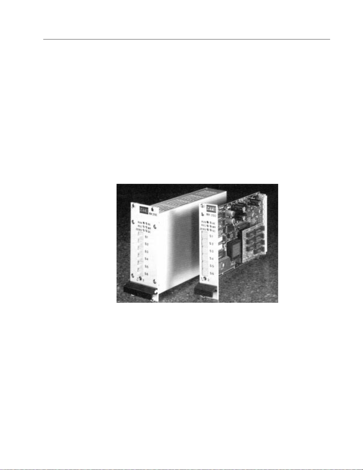
1. Introduction to the MK292 Digital Output Module
The MK292 Digital Output Module provides an interface between a Temposonics position sensor with
a pulse-width modulated or start/stop output and a system controller. A selection of outputs from the
MK292 (BCD, binary, or Gray Code) gives this device nearly universal compatibility.
The MK292 is compatible with many Temposonics position sensors, as follows:
Compatible Position Sensors:
• SE-based Temposonics LP sensor with start/stop output
• Temposonics II sensors with a pulse-width modulated or start/stop output
• Temposonics L Series sensors with a pulse-width modulated or start/stop output
In addition to position data, the MK292 generates logic outputs: DATA READY and ERROR; and logic
input: DATA HOLD. An optional sub-board assembly provides an analog output for recording purposes (output range: 0 to 10 Vdc or 10 to 0 Vdc).
The MK292 can be configured as either a rack-mountable card or module that can be installed in a
standard 19 inch mounting rack.
Figure 1-1
MK292 (Module version, left; card version, right)
1
Page 6
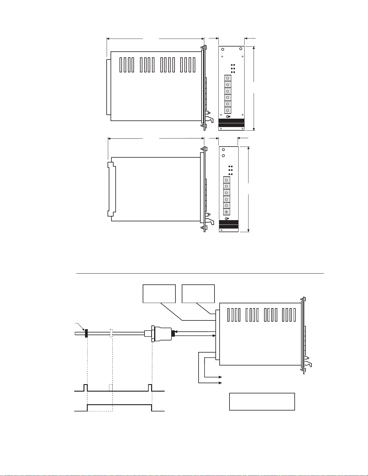
Figure 1-2
MK292 Digital Output Module Dimensions
1.1 System Configuration
Figure 1-3
Typical System Configuration
MK292
Module
Magnet
Temposonics Sensor with
Start/Stop or PWM Output
Start/Stop Output
Max. Resolution: 0.002 in. (0.05 mm)
PWM Output
Max. Resolution: 0.0002 in. (0.005 mm)
24 Vdc
Power Suppy
Required
5 Vdc
Required for
TTL Output
Selectable: BCD, Binary, or Gray Code Displacement Output
Optional Voltage Output (0 to 10 Vdc or 10 to 0 Vdc)
for recording purposes only
NOTE:
BCD outputs are limited to a maximum
stroke length of 99.99 inches (2540 mm)
R
E
M
RUN
REC
ZER
l
MK 292
S
S
S
S
S
S
R
E
M
RUN
REC
ZER
l
MK 292
S
S
S
S
S
S
1.19 in.
30.2 mm
1.98 in.
50.4 mm
MK 292
Module
MK 292
Card
6.7 in.
170 mm
6.7 in.
170 mm
5.06 in.
128.4 mm
5.06 in.
128.4 mm
2
Page 7

2. Specifications
2.1 MK292 Digital Output Module Specifications
Parameter Specification
Input Voltage: 24 Vdc (-15%/+20%); Ripple: < 5%
NOTE:
An additional 5V power supply is required for the optional TTL level outputs;
dual power supply (24/5 Vdc) is available from MTS, P/N 380066
Current Draw: 250 mA maximum
Input Requirement: SE-based Temposonics LP with start/stop output*
Temposonics II with PWM or start/stop output
Temposonics L Series with PWM or start/stop output*
Output Format: (Selectable): Up to 24 bit:
• BCD
(maximum stroke length with BCD output scaled in millimeters is 7500 mm. When utilizing
inches, strokes may be up to 300 inches)
• Natural Binary
• Gray Code
Resolution: 0.002 in. (0.05 mm) with start/stop input
0.0002 in. (0.005 mm) with PWM input
Update Frequency: Stroke and resolution dependent
Optional Analog (Recorder) Output :Range: -10 to +10 Vdc
(used for recording; option board required - must be specified upon initial order)
12 bit resolution
5mv ripple
Fully adjustable
Programming Parameters: Zero
Resolution
Stroke Length
Measuring Direction
Analog Output
(used for recording; option board required - must be specified upon initial order)
Operating Temperature: 0 to 60°C (32 to 140°F)
Connection: 64 pin edge connector (DIN 41612; provided with circuit card)
Cable Requirements: 8 x 24 AWG, twisted pairs, shielded low capacitance cable (BELDEN 8105 or equivalent)
w/appropriate number of conductors for sensor used
Maximum Cable Length: Sensor with RS422 output: 500 meters (1640 ft.)
Sensor with PWM output: 152.4 meters (500 ft.)
Dimensions: MK292 Card, Front Panel: 30.2 x 128.4 mm (1.19 x 5.06 in.)
MK292 Module, Front Panel: 50.4 x 128.4 mm (1.98 x 5.06 in.)
* When using the MK292 with a Temposonics LA or LP sensor, please contact Applications Engineering.
Specifications are subject to change without notice. Consult MTS for verification of specifications critical to your application.
3
Page 8

2.2 Temposonics Position Sensor Specifications
For detailed specifications and installation requirements for the position sensors, refer
to the appropriate document, as follows:
• Temposonics II Sensor Installation and Instruction Manual (P/N 550055)
• SE-based Temposonics LP Installation Guide (P/N 550582)
• Temposonics L Series/Digital Product Specification (P/N 550539)
Parameter Specification
Input Voltage: Powered from MK292 Module
Stroke Length: Temposonics II: Up to 300 inches (7620 mm)
SE-based Temposonics LP: Up to 48 inches (1219 mm)
Temposonics L Series: Up to 120 inches (3048 mm)
Non-linearity: Temposonics II: < ±0.05% of full scale or ± 0.002 inch (±0.05 mm), whichever is greater
SE-based Temposonics LP: ± 0.1% of full scale or ± 0.004 in. (±0.10 mm), whichever is greater
Temposonics L Series: 0.03% of full scale
Repeatability: ± 0.001% of full scale or ±0.0001 inch (± 0.002 mm), whichever is greater
Operating Temperature: Head Electronics: - 40 to 150°F (- 40 to 66°C)
Sensor Rod: - 40 to 185°F (- 40 to 85°C)
Operating Pressure: Temposonics II Rod-Style Sensors: 3000 psi continuous, 8000 psi static typical
Temposonics L Series Rod-Style Sensors (Model LH): 5000 psi continuous, 10,000 psi static
Outputs (absolute): Start/stop or PWM configured for
external
interrogation
Mounting Distances: Sensor with RS422 output to MK292: 500 meters (1640 ft.)
Sensor with PWM output to MK292: 152.4 meters (500 ft.)
MK292 to PLC: 25 meters (82 ft.)
Specifications are subject to change without notice. Consult MTS for verification of specifications critical to your application.
NOTE (Zero Points):
Before ordering an MK292 with a Temposonics LA
or LP sensor, consult an MTS Sensors Division
Applications Engineer for details regarding the
positioning of the sensor’s ZERO point.
4
Page 9
3. System Components
3.1 MK292-Compatible Temposonics Position Sensors
To interface with the MK292, a start/stop or pulse-width modulated output (see figure
3.1) is required from the Temposonics position sensor. The MK292 will convert these
signals into a parallel BCD, Gray Code, or binary output.
COMPATIBLE SENSORS
3.1.1. Temposonics Position Sensor with Start/Stop Output
Temposonics L Series and LP position sensors provide a direct RS422 compatible
start/stop output. Temposonics II position sensors require an RS422 Personality
Module (RPM), installed in the sensor head, to produce a start/stop output.
3.1.2. Temposonics Position Sensor with Pulse-Width Modulated (PWM) Output
Temposonics L Series position sensors provide a direct pulse-width modulated output.
Temposonics II position sensors require a Digital Personality Module (DPM) to generate a pulse-width modulated output. The DPM is installed in the head of the sensor's
electronics enclosure.
When using a Temposonics sensor with a PWM output, "external interrogation" is
required to interface with the MK292. External interrogation is an option selected at
the time of order and is pre-set at the factory.
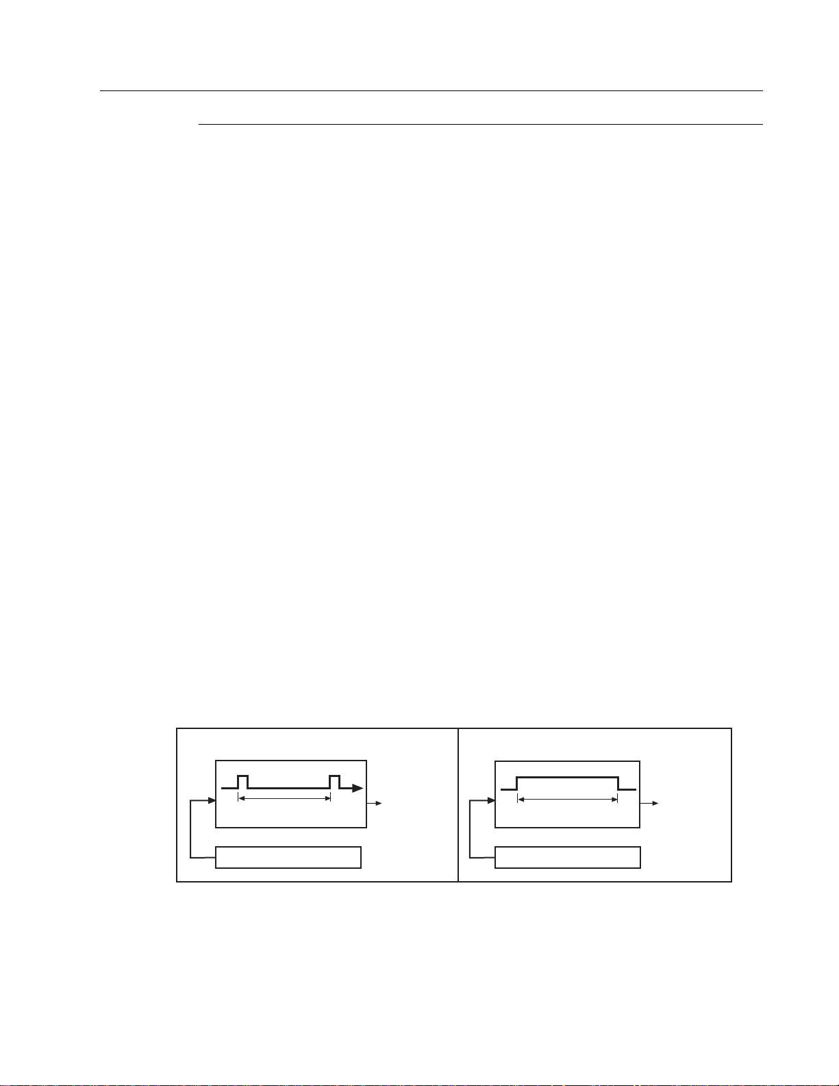
3.1.3. Temposonics Position Sensor with Synchronous Operation (External
Interrogating)
In synchronous operation, an interrogation pulse is supplied to the position sensor
from the MK292 module. After supplying the interrogation pulse, the MK292 waits for
the sensor's return pulse, then ends the cycle. The time between the launching of the
interrogation pulse and the receipt of the return pulse is proportional to the distance
between the null or zero position and the movable magnet.
Figure 3-1
Start/stop and PWM Outputs
RS422 Compatible
Start/Stop Output
To MK292 Module
Distance between Start and Stop pulse
is proportional to magnet position
Temposonics Position Sensor
To MK292 Module
Temposonics Position Sensor
Pulse Duration Output
Pulse duration is
proportional to position
StartStop
5
Page 10

4. Connections
4.1.1 Temposonics II Position Sensors with DPM or RPM
Table 4-A Connections - Temposonics II Position Sensor
MK292 Wire Color Wire Color Function Function
Connections Pin No. (Striped Leads) (Solid Leads) w/PWM Output w/Start/Stop Output
C32 1 White/Blue Stripe White DC Ground DC Ground
C32 2 Blue/White Stripe Brown Frame Frame
C28 3 White/Orange Stripe Gray (-) Gate Out (-) Start/Stop Pulse
C27 4 Orange/White Stripe Pink (+) Gate Out (+) Start/Stop Pulse
C30 5 White/Green Stripe Red + 15 Vdc + 15 Vdc
C31 6 Green/White Stripe Blue - 15 Vdc - 15 Vdc
No Connection 7 White/Brown Stripe Black Not Used Not Used
No Connection 8 Brown/White Stripe Violet Not Used Not Used
C24 9 White/Gray Stripe Yellow (+) Interrogation (+) Interrogation
C25 10 Gray/White Stripe Green (-) Interrogation (-) Interrogation
NOTE:
Verify if the cable has striped or solid color leads and make connections accordingly.
Figure 4-1
10 Pin 'RB' Style Connector
(Mating Connector: P/N 400755-3)
4.1.2 SE-based Temposonics LP Position Sensors with Start/Stop Output
Table 4-B Connections - SE-based Temposonics LP Position Sensor
MK292 Sensor
Connections Pin No. Wire Color Function
C28 1 Blue Gate (-)
C27 2 Green Gate (+)
C25 3 Yellow Interrogation (-)
C24 4 Orange Interrogation (+)
C30 5 Red Power, provided by MK292 (+15, ± 10%)
C32 6 Black Ground
No Connection 7 Drain Shield Drain Wire
No Connection 8 N/A N/A
Figure 4-2a Figure 4-2b
Integral Connector Hanging Connector
Connection Type C, Connection Type H or J,
External View External View
1 2
3
6
5
8
4
7
1 2
3
6
5
8
4
7
1
2
3579
46810
6
Page 11

4.1.3 Temposonics L Series Position Sensors with Start/Stop Output
Table 4-C.1 Connections - Temposonics L Series Position Sensor with RG Connector
MK292
Connection Pin No. Wire Color Function
C28 1 Gray (-) Gate
C27 2 Pink (+) Gate
C24 3 Yellow (+) Interrogation
C25 4 Green (-) Interrogation
C2 5 Red or Brown Power supplied by MK292 (+ 24 Vdc)
C32 6 White DC Ground
7 - No Connection
Figure 4-3
RG Connector
Table 4-C.2 Connections - Temposonics L Series Position Sensor with MS Connector
MK292
Connection Pin No. Wire Color Function
C32 A White DC Ground
B - No Connection
C28 C Gray (-) Gate
C27 D Pink (+) Gate
C2 E Red Power supplied by MK292 (+ 24 Vdc)
F - No Connection
G - No Connection
H - No Connection
C24 J Yellow (+) Interrogation
C25 K Green (-) Interrogation
Figure 4-4
MS Connector
(Mating Connector: P/N 370013)
A
B
C
D
E
F
G
H
J
K
2
1
6
5
4
3
7
CAUTION!
When wiring Temposonics L Series sensors, DO NOT
connect DC ground to the cable shield or drain wire.
7
Page 12

Table 4-C.3 Connections - Temposonics L Series Position Sensor with RB Connector
MK292
Connection Pin No. Wire Color Function
C32 1 White DC Ground
2 - No Connection
C28 3 Gray (-) Gate
C27 4 Pink (+) Gate
C2 5 Red Power supplied by MK292 (+ 24 Vdc)
6 - No Connection
7 - No Connection
8 - No Connection
C24 9 Yellow (+) Interrogation
C25 10 Green (-) Interrogation
Figure 4-5
RB Connector
(Mating Connector: P/N 400755-3)
Table 4-C.4 Connections - Temposonics L Series Position Sensor with RO Integral Cable
MK292
Connection Wire Color Function
C28 Gray (-) Gate
C27 Pink (+) Gate
C24 Yellow (+) Interrogation
C25 Green (-) Interrogation
C2 Red or Brown Power supplied by MK292 (+ 24 Vdc)
C32 White DC Ground
Table 4-C.5 Connections - Temposonics L Series Position Sensor with HO Integral Cable*
MK292
Connection Wire Color Function
C28 White (-) Gate
C27 Black twisted w/white (+) Gate
C24 Blue (+) Interrogation
C25 Black twisted w/blue (-) Interrogation
C2 Red Power supplied by MK292 (+ 24 Vdc)
C32 Black twisted w/red DC Ground
*The HO Integral Cable [maximum length 30 feet (9.14 m)] was not available at the time
this manual was printed. Please contact the factory for status.
1
2
3579
46810
8
Page 13

4.2 System Connections
NOTES:
1. Logic inputs and outputs are relative to voltage level connected to Vin (Pin c3). For example, set Vin to 5 Vdc for TTL, or 24
Vdc for controller with 24 Vdc inputs/outputs.
2. The five digit BCD outputs are limited to stroke lengths ≤7500 mm when measuring in millimeters. When measuring in
inches, BCD output is available for stroke lengths up to 300 inches.
3. When using a PWM output, the sensors must be configured for external interrogation.
Figure 4-6
System Connections
DC Common
+ 24V Input to MK292
5-24V Input for TTL Output
Error
Data Ready
Master/Start Output
PWM or Start/Stop
Master/Slave Input
mm/Inch
c11
c12
Vin
0V
c11
c12
Vin
0VParallel
BCD Output
(Note 2)
Parallel
Binary Output
Parallel
Gray Output
c11
c12
0V
1
2
3
4
1
2
3
4
1
2
3
4
1
2
3
4
1
2
3
4
1
2
3
4
1
2
3
4
5
6
MSB
LSB
0
1
2
3
4
5
6
7
8
9
10
11
12
13
14
15
16
17
18
19
20
21
22
23
BCD Natural Binary
or Gray Code
Polarity (+/-)
Displacement Output Format
c15
Vin Negative
c15
0V Positive
Displacement
Output Format
Output Logic
c10
Vin
PWM
(Note 3)
c10
0V Start/Stop
PWM or Start/Stop
c1 or a1
c1 or a1
c1 or a1
c2 or a2
c2 or a2
c2 or a2
c2 or a2
c1 or a1
c1 or a1
c1
c2
c3
0 V
24 V
Vin
For 5 - 24 V input
IMPORTANT: 5 V required for TTL
(Note 1)
c1
c2
c3
0 V
24 V
EXAMPLE:
Controller with 24 V inputs
c1 or a1
c2 or a2
c3 or a3
c5
c6
c7
c10
c11
c12
c13
c14
c15
c16
c17
c19
c20
c24
c25
c27
c28
c30 or a30
c31 or a31
c32 or a32
a4
a5
a6
a7
a8
a9
a10
a11
a12
a13
a14
a15
a16
a17
a18
a19
a20
a21
a22
a23
a24
a25
a26
a27
a28
MK 292
Digital
Output
Module
When high, output is negative (-);
when low, output is positive (+)
Sensor Connections
(Wire color is sensor dependent refer to Section 4.1 of this manual)
(+) Interrogation
(-) Interrogation
(+) Gate or (+) Start/Stop Pulse
(-) Gate or (-) Start/Stop Pulse
+ 15 Vdc
- 15 Vdc
DC Ground
Frame
Output
Output
Input
Optional Analog Output
DC Common
DC Common
DC Common
Output Logic (+/-)
External Start Input
Data Hold Input
c14
Vin Inches
c14
0V Millimeter
Unit of Measurement
c1 or a1
c2 or a2
9
Page 14

4.3 Functional Inputs/Outputs
OUTPUTS:
Voltage Level: TTL level to 24 Vdc
Maximum Current Load: 20 mA (high level)
INPUTS:
Control Signal Level: ≥ applied Vin level
Current Load per Input: < 1 mA
4.3.1 Error Output (Loss of Feedback)
Pin: c5
Logic: HIGH: No Error; LOW: Error
Figure 4-7 Error Outputs
Errors:
• No sensor magnet
• Sensor magnet not positioned within the active range of sensor
• Malfunction or failure of sensor or module
• Electronic interference
4.3.2 Data-Ready Output (Latch Pulse)
Pin: c6
Logic: HIGH
Ensures that parallel data transfer does not occur during data update
(i.e., during change in magnet position). In addition, the data ready
output confirms that the data is up-to-date.
The timing of data transfer is illustrated below.
Figure 4-8 Data Ready
60 µs 60 µs
Cycle
Time
Data
Ready
Data
Changing
c5
HIGH = No Error LOW = Error
10
Page 15

4.3.3 Data-Hold Input (Latch Inhibit)
Pin: c17
Logic: HIGH
Data Hold is another means, besides Data Ready, to ensure that parallel data transfer does not occur during data update. When Data Hold
(C17) is high, data does not update.
4.3.4 External Start Input (Features)
Pin: c16
Logic: HIGH
The External Start Input permits the timing of the measuring cycle
(i.e., the interrogation pulses) to originate from an outside source.
The Master/Slave Input (see below) logic must be HIGH before the
sensor can be interrogated, normally it is set LOW.
Start signals must be between 6 to 10 microseconds in duration and
repetition period must exceed the minimum cycle time -- refer to programming section of the manual: (MR) Measuring Range.
Figure 4-9 External Start
4.3.5 Master/Slave Input (Features)
Pin: c13
Logic: HIGH
If an application requires that more than one Temposonics position
sensor provide position data simultaneously, the Master/Slave Input
may be used. It is essential to identify the longest position sensor as
the master device since it possesses the longest cycle time. The master "start" command is switched to output 'c7' and linked to slave output 'c16' (External Start Input).
Figure 4-10 Master/Slave
Master
c7
c13
Slave
c16
c13
Slave
c16
Vin
6 - 10 µs
Minimum
Cycle Time
11
Page 16

5. System Parameters
After the MK292 Digital Output Module is installed and connected to the Temposonics position sensor,
system parameters must be set before start-up. When setting the system parameters, you must be
aware which electronics module is installed in the Temposonics position sensor. Verify that the sensor
has either a start/stop or PWM output. If the sensor has a PWM output, also verify that it is configured for external interrogation. Contact an MTS Applications Engineer if you have any questions
regarding the configuration of your sensor or how to interface to the MK292 unit.
The system parameters for each configuration are indicated below:
SYSTEM PARAMETERS SYSTEM PARAMETERS
(Sensor with PWM Outputs) (Sensor with Start/Stop Outputs)
< <
< <
NOTE:
Pulse Duration (REC) only applies to systems that are using sensors with a PWM output.
< <
< <
< <
< <
System parameters are set via the front panel of the MK292 using the programming and BCD switches.
• Programming Switch
This momentary toggle switch is located at the bottom of the front panel. It has two activation positions: #1 and #2. Programming Modes are accessed by manipulation of this switch as defined in the
Programming section of this manual.
Figure 5-1
Programming Switch Positions
When the Programming Switch is pushed into either Position #1 or Position #2 it will automatically
return to the center (normal) position when released.
Position #1 Position #2Normal
Position
ZERONull AdjustmentZERO
MRMeasuring RangeMR
REResolutionRE
SCScaling FactorSC
N/APulse DurationREC
RUNProgramming ModeRUN
12
Page 17

• BCD Switches (S1-S6)
The six rotary switches, S1 (least significant digit) to S6 (most significant digit), are used to set parameter values. A screw driver or adjusting tool is used to set the switches.
The input values are checked against the actual values as indicated by the customer provided controller display.
• LEDs
There are six LEDs, one red and five green, which give visual indication of the operating condition and
programming mode of the MK292.
1. RED (continuous light) = System in operation mode
2. RED (flashing light) = Transition to programming mode
3. GREEN (continuous light) = Indication of selected parameter
4. GREEN (flashing light) = Programming mode is activated – parameter settings can be
changed via BCD switches S1-S6.
5. GREEN (fast flashing light) = Input error
Figure 5-3
BCD Switch
Figure 5-2
Front Panel of MK292 Module
2
3
8
1
5
4
6
7
9
0
RE
MR
SC
RUN
REC
ZERO
S1
S2
S3
S4
S5
S6
MK 292
LEDs
BCD Switches
Programming Switch
1 2
13
Page 18

6. Short Form Programming Procedure
• Programming Mode
Hold the programming switch in Position #1 (see Fig. 6.1) until the 'RUN' LED begins to
flash (≈ 3 sec.) Programming Mode is set up.
• Selection of System Parameters
To select desired parameter, momentarily toggle the programming switch to Position #1 and
release; an LED will light. Repeat until the LED is lit next to desired parameter.
• Parameter Adjustment
Enter desired values using BCD switches S1-S6 (S1 represents the least significant digit). Rapid
flashing of the green LED indicates input error.
• Parameter Setup
To store a newly set parameter, hold the programming switch in Position #2 (see Fig. 6.1)
until the LED of the next parameter is activated (≈ 3 sec.)
• Operation Mode
Hold the programming switch in Position #1 until the red "RUN" LED is activated. This indicates that the Programming Mode has been exited and the Operation Mode is ready.
Figure 6-1
Programming Switch Positions
For detailed instructions on programming the MK292 Digital Output Module, refer to Section 7 of this
manual.
Position #1 Position #2Normal
Position
NOTE:
If the value cannot be stored, momentarily hold the
programming switch in Position #1, and repeat, until
you cycle through to the desired parameter.
NOTE:
You may cycle through and check the parameters by
observing the controller display as you repeatedly put
the programming switch in Position #1.
To change a parameter: Select desired parameter, then
simply hold the programming switch in Position #2
until the LED flashes (≈3 sec.). Change parameter
using the BCD switches.
14
Page 19

7. Detailed Programming Procedure
7.1 (RUN) Programming Mode / Red LED
During initial start-up, the red 'RUN' LED will flash. This indicates that the MK292 is in
the programming mode and input parameters are required for operation.
If the 'RUN' LED is on, but not flashing, this means that parameters have already been
set. If parameters must be changed, the programming mode must be accessed, as follows:
Hold programming switch in Position #1 until 'RUN' LED flashes (≈ 3 sec.)
ADJUST
7.2 (REC) Pulse Duration / Green LED
Temposonics sensors with a PWM output are capable of “circulations”, meaning that
the interrogation and return signals can be recirculated a specific number of times.
This lengthens the duration of the PWM output from the sensor and the counting time
of the MK292; the result is increased resolution.
The number of circulations is determined at the time of order and is reflected in the
sensor’s model number. Refer to the appropriate ordering guide for the sensor that
you are using to determine the circulation count. If you have any questions regarding
this, contact an MTS Applications Engineer.
NOTE:
This parameter only applies to systems that have a
Temposonics position sensor with a PWM output. In
the procedure, this step will not occur if the MK292 is
configured for a start/stop output.
RUN
15
Page 20

1) Hold the programming switch in Position #2 until the 'REC' LED is flashing (≈ 3 sec.)
ADJUST 2) Enter the Pulse Duration (recirculation value) using BCD switches S1-S6.
Example:
Resolution vs. Circulations
Maximum Minimum Circulation Count
See note above 0.00025 16
0.00025 0.0005 8
0.0005 0.001 4
0.001 0.002 2
0.002 0.004 1
Maximum Resolution Formulas:
• Resolution in millimeters = (0.0508 ÷ Circulation Count)
• Resolution in inches = (0.002 ÷ Circulation Count)
Switch Setting: PWM Output (circulations)
BCD Switch Circulations: 4 Circulations: 16
S1 4 6
S2 0 1
S3 0 0
S4 0 0
S5 0 0
S6 0 0
1) Hold the programming switch in Position #2 until the 'SC' LED is flashing (≈ 3 sec.)
ADJUST
The MK292 is now ready to accept the next parameter – Scale Factor (SC).
REC
NOTE:
The chart below defines the MK292-programmable resolutions. It is important to note that with resolution
finer than 0.0002 in., instabilities will be detected on
the Least Significant Bits.
REC
16
Page 21

7.3 (SC) Scaling Factor / Green LED
Each Temposonics position sensor has its own specific scale factor (gradient) which
describes the velocity of the torsional strain pulse through the waveguide medium
(refer to 'Principle of Operation'). The gradient is indicated on the sensor's label. Upon
initial start-up or when replacing sensors, this value must be set to recalibrate system.
1) Momentarily tap the programming switch to Position #1, the 'SC' LED will light.
ADJUST 2) Hold the programming switch in Position #2 until the 'SC' LED begins to flash (≈ 3 sec.)
3) Enter the scale factor indicated on the sensor label using the BCD switches (S1 - S6).
Example: Gradient = 8.94371
BCD Switch # Settings
S1 1
S2 7
S3 3
S4 4
S5 9
S6 8
SC
IMPORTANT
Scale Factor or Gradient
For stroke lengths defined in inches (Pin c14 set for inches), the
scale factor or gradient is described in microseconds per inch.
This value is indicated on the sensor's label (see Fig. 7.3).
For stroke lengths defined in millimeters (Pin c14 set for millimeters), the scale factor or gradient is described in meters per second.
The formula to convert µs/in, to m/s is as follows:
(Scale in m/s) = 25,400 ÷ (Scale in µs.in.)
Example:
Scale (Gradient) = 8.94371 µs/in.
25,400 ÷ 8.94371 µs/in = 2839.98 meters/second
17
Page 22

Hold the programming switch in Position #2 until the 'RE' LED is lighted (≈ 3 sec.)
SETUP
The MK292 is now ready to accept the next parameter – Resolution (RE).
7.4 (RE) Resolution / Green LED
The resolution that can be achieved by the MK292 is dependent on the input from the
Temposonics position sensor. The chart below indicates the range of resolutions
depending on sensor type. Note that sensors with PWM output must be set for the
appropriate number of circulations to achieve desired output resolution.
RESOLUTION
Start/Stop Output
Range: 0.1 in. to 0.002 in. or 2.54 mm to 0.05 mm
PWM Output
Range: 0.1 in. to 0.0002 in. or 2.54 mm to 0.005 mm
(Note: Refer to Resolution vs. Circulation Chart, page 16)
1) Hold the programming switch in Position #2 until the 'RE' LED begins to flash (≈ 3 sec.)
ADJUST 2) Enter the desired resolution using BCD switches S1 - S6.
Table 7A
Table 7B
Hold the programming switch in Position #2 until the 'MR' LED begins to flash (≈ 3 sec.)
SETUP
The MK292 is now ready to accept the next parameter – Measuring Range (MR)
RE
SWITCH SETTINGS / RESOLUTION IN MILLIMETERS
Switches 0.005 mm 0.01 mm 0.05 mm 0.1 mm 0.5 mm 1.0 mm
S1 (0.00X) 5 0 0 0 0 0
S2 (0.0X) 0 1 5 0 0 0
S3 (0.X) 0 0 0 1 5 0
S4 (X.0) 0 0 0 0 0 1
S5 0 0 0 0 0 0
S6 0 0 0 0 0 0
SWITCH SETTINGS / RESOLUTION IN INCHES
Switches 0.0002 in. 0.0004 in. 0.002 in. 0.004 in. 0.02 in. 0.039 in.
S1 (0.000X) 2 4 0 0 0 0
S2 (0.00X) 0 0 2 4 0 9
S3 (0.0X) 0 0 0 0 2 3
S4 (0.X) 0 0 0 0 0 0
S5 0 0 0 0 0 0
S6 0 0 0 0 0 0
RE
SC
18
Page 23

7.5 (MR) Measuring Range / Green LED
The measuring range or "stroke length" of the sensor must be set accurately to optimize the interdependence of the other parameters. This value is indicated on the sensor label as "stroke" and will be in either inches or millimeters.
1) Hold the programming switch in Position #2 until the 'MR' LED begins to flash (≈ 3 sec.)
ADJUST 2) Enter the measuring range using BCD switches S1 - S6.
Example:
Update Time Formula:
Tud = [(Lm + 120 mm) (13) (N)] ÷ 36
Where:
Update Time (in milliseconds) = Tud
Length in mm = Lm
Circulation Count = N
1) Hold the programming switch in Position #2 until the 'ZERO' LED begins to flash (≈3 sec.)
SETUP
The MK292 is now ready to accept the next parameter -- Null Adjust (ZERO).
MR
NOTE:
When the measuring range is set, the measuring frequency and system update time is also set. Refer to the
tables below to see the relationship of measuring
range, frequency, and update time.
MILLIMETERS
Measuring Range: 1525 millimeters
Switch (mm) Setting
S1 (1.0) 5
S2 (10) 2
S3 (100) 5
S4 (1000) 1
S5 (n/a) 0
S6 (n/a) 0
INCHES
Measuring Range: 120.5 inches
Switch (in.) Setting
S1 (0.1) 5
S2 (1.0) 0
S3 (10) 2
S4 (100) 1
S5 (n/a) 0
S6 (n/a) 0
MR
NOTE:
Pin c14 of the MK292 permits you to select the unit of
measurement (i.e., inches or millimeters) and must be
wired accordingly (refer to section 4.2).
19
NOTE:
When using inches, use the following
formula to convert inches to millimeters:
Inches x 25.4
Page 24

7.6 (ZERO) Null Adjust / Green LED
Null adjust allows you to set the mechanical ZERO position anywhere within the
active measuring range of the position sensor. Move the sensor magnet to the desired
ZERO position and proceed as follows:
1) Hold the programming switch in Position #2 until the 'ZERO' LED begins to flash (≈3 sec.)
ADJUST
The displacement output indicates position without the offset calculation
2) Set switches S1-S6 to ZERO position.
1) Hold the programming switch in Position #2 to restart programming sequence. (≈ 3 sec.)
SET UP
7.7 (ZERO) Offset
As an alternative to the ZERO/NULL adjust, a ZERO/NULL offset can be programmed
within a range of -49.9999 to +49.9999 inches. The value depends on the pre-set resolution of the position sensor. The offset is set by using S6 only.
Forward Acting - Positive offset counts down when magnet is moved to the head and
counts up when moved to the tip.
Reverse Acting - Negative offset counts up when magnet is moved to the head and
counts down when moved to the tip.
Positive Offset Negative Offset
0 = +0 5 = -0
1 = +1 6 = -1
2 = +2 7 = -2
3 = +3 8 = -3
4 = +4 9 = -4
NOTE:
If a set value is overwritten, the programming mode
has to be set again by repeatedly tapping the dip
switch to position #1.
ZERO
ZERO
20
Page 25

Move the magnet to the desired mechanical start position and calibrate the offset as
follows:
1) Hold the programming switch in Position #2 until the 'ZERO' LED begins to flash (≈3 sec.)
ADJUST
The displacement output indicated position without the offset calculation
2) Enter the desired offset value using BCD switches S1-S6.
EXAMPLE: Switch Settings S1-S6 for Offset Value
1) Hold the programming switch in Position #2 to restart programming sequence. (≈ 3 sec.)
SET UP
NOTE:
If a set value is overwritten, the programming mode
has to be set again by repeatedly tapping the dip
switch to Position #1.
OFFSET
NEGATIVE OFFSET (in inches)
BCD Switch -00.3571 -04.5841 -03.5705 -45.8405
S1 1 1 5 5
S2 7 4 0 0
S3 5 8 7 4
S4 3 5 5 8
S5 0 4 3 5
S6 5 5 5 9
POSITIVE OFFSET (in inches)
BCD Switch +00.3571 +04.5841 +03.5705 +45.8405
S1 1 1 5 5
S2 7 4 0 0
S3 5 8 7 4
S4 3 5 5 8
S5 0 4 3 5
S6 0 0 0 4
OFFSET
21
Page 26

7.8 (RUN) Operation Mode / Red LED
1) Hold the programming switch in Position #1 until the 'RUN' LED begins to flash (≈ 3 sec.)
SETUP
The Programming Mode is exited and all parameter settings are stored in an EEPROM
within the MK292 module. You are now in Operation Mode.
RUN
22
Page 27
8. Optional Analog Output for the MK292 (for Recording Purposes Only)
The analog output option functions in two operational modes:
1. Normal (NORM)
2. Programmable Adjustment (PROG)
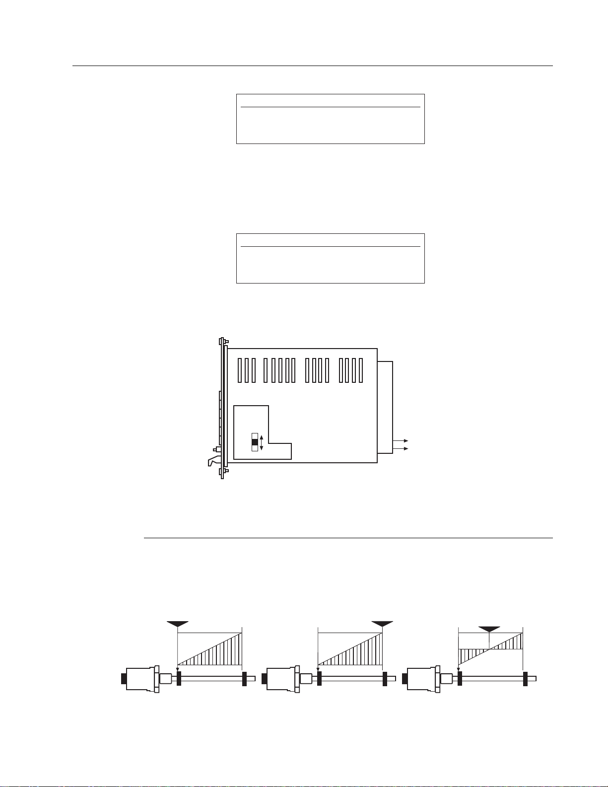
Operation mode is selected with the switch on the analog sub-print board (see Fig. 8.1).
Figure 8-1
8.1 Operation Mode 1 (Normal)
Analog Sub-print Switch (S1) = NORM
The analog output configuration is defined by the zero position and measuring range
of the sensor. The three possible configurations are illustrated in Fig. 8.2.
Figure 8-2
Null Set-Up
+10 V
0 V
No. 1
Null Set-Up
0 V
-10 V
No. 2
Null Set-Up
+5 V
0 V
-5 V
No. 3
MK 292
Module
c19
c20
- 10 to + 10 Vdc
0 Vdc
NORM
PROG
Analog
Subprint
WARNING!
When powering down during analog operation, switch
must remain in programming mode or all parameters
will be lost.
NOTE:
The analog output is available as an option and must
be specified at the time of order. An additional analog
sub-print is required.
23
Page 28

If the magnet leaves the defined measuring range of the sensor, the system will indicate the following outputs:
1. If the magnet leaves the measuring range moving towards the end of the sensor
rod, the output voltage will be NEGATIVE.
2. If the magnet leaves the measuring range moving toward the electronics head of
the sensor, the output will be a constant +10V.
8.2 Operation Mode 2 (Programmable Adjustment)
The analog output configuration can be set-up by defining the desired output range of
the sensor with two set-points (SP1 and SP2).
Switch S1 = ON (PROG)
SP1 Programming:
1.) Move the magnet to the desired SP1 position.
2.) Hold the programming switch in Position #1 until the RUN LED begins to flash (≈ 3 seconds)
Programming Mode is set up.
3.) Momentarily toggle the programming switch to Position #1 and release and repeat until ZERO + SC become lit.
4.) Hold the programming switch in Position #2 until SC begins to flash (≈3 seconds). ZERO is also lit.
5.) Enter the desired analog out at SP1 using the BCD switches (S1 = least significant bit, S5 = most significant bit).
6.) Hold the programming switch in Position #2 until SC is lit (≈3 seconds). ZERO is also lit.
7.) The output value at SP1 is now stored.
SP2 Programming:
1.) Move the magnet to the desired SP2 position
2.) Hold the programming switch in Position #1 until the RE LED begins to flash (≈3 seconds). ZERO is also
lit.
3.) Enter the desired analog out at SP2 using the BCD switches (S1 = least significant bit, S5 = most significant bit).
4.) Hold the programming switch in Position #2 until SC is lit (≈3 seconds). ZERO will no longer be lit.
5.) Hold the programming switch in Position #1 until the RUN LED is lit (≈ 3 seconds).
The output value at SP2 is now stored and the system has entered the Operations Mode.
NOTE:
Setting up a value outside the valid voltage range will
be detected and RE will flash rapidly to indicate an error.
NOTE:
Setting up a value outside the valid voltage range will
be detected and SC will flash rapidly to indicate an error.
IMPORTANT NOTES:
• SP1 and SP2 must be within the valid measuring range
• SP1 must be located nearer the sensor head than SP2
• SP1 and SP2 can have output values between -10 V
and +10 V
24
Page 29

EXAMPLE, BCD Switch Settings
NOTE:
To configure a negative setpoint value: S6 ≥5.
SP1 = + 7.565 V SP2 = - 9.480 V
S1 = 5 S1 = 0
S2 = 6 S2 = 8
S3 = 5 S3 = 4
S4 = 7 S4 = 9
S5 = 0 S5 = 0
S6 = 0 S6 = 9
25
Page 30

l
MTS Systems Corporation
Sensors Division
3001 Sheldon Drive
Cary, NC 27513 USA
Phone: 800-633-7609
Fax: 919-677-0200
MTS Sensor Technologie
Gmb and Co. KG
Auf dem Schüffel 9
D-58513 Ludensheid
Federal Republic of Germany
Phone: +49-23-5195870
Fax: +49-23-5156491
MTS Sensors Technology Corp.
Izumikan Gobancho
12-11 Gobancho
Chiyoda-ku, Tokyo 102
Japan
Phone: +3-3239-3003
Fax: +3-3262-7780
Temposonics is a registered trademark of MTS Systems Corporation.
All Temposonics products are covered by US patent number 5,545,984.
Other patents pending.
0797 550414 Revision B
© 1997 MTS Systems Corporation
 Loading...