

Page 1
Level Plus
Magnetostrictive Liquid-Level Sensors
Temposonics
with
®
Technology
®
®
SENSORS
M-Series Model MR
Transmitter with Analog Output
Document Part Number
550731 Revision E
Electronics Replacement Instructions
M-Series Model MR Transmitter Electronic Module Removal and installation instructions
The Level Plus® Model MR level transmitter is modular in design. The
electronics module can be replaced in the field without on site MTS
applications engineering support.
Before you begin
• Ensure that all power is disconnected
• Follow all lockout procedure(s) are followed prior to opening
the transmitters instrumental housing.
To replace the M-Series electronics module, complete the following
steps:
1. Remove any dirt, debris, or liquid from the top of the instru
ment enclosure.
2. Remove the instrument housing cover.
3. Remove the existing transmitter electronics module, or puck,
by grasping the perimeter of the puck and pulling it firmly
upwards away from the base.
4. Install the new puck by aligning the connectors at the bottom
of the puck with the appropriate connectors in the base of the
instrument enclosure. Using even pressure on the face of the
puck, press down firmly. Check that the puck is replaced
correctly, by pressing down around on the perimeter of the
puck face. The puck should feel secure and not “rock”.
5. Refer to the M-Series Operation and Installation Manual, part
number 550720, (available at www.mtssensors.com) for
calibration and setup instructions.
6. Replace the instrument housing cover.
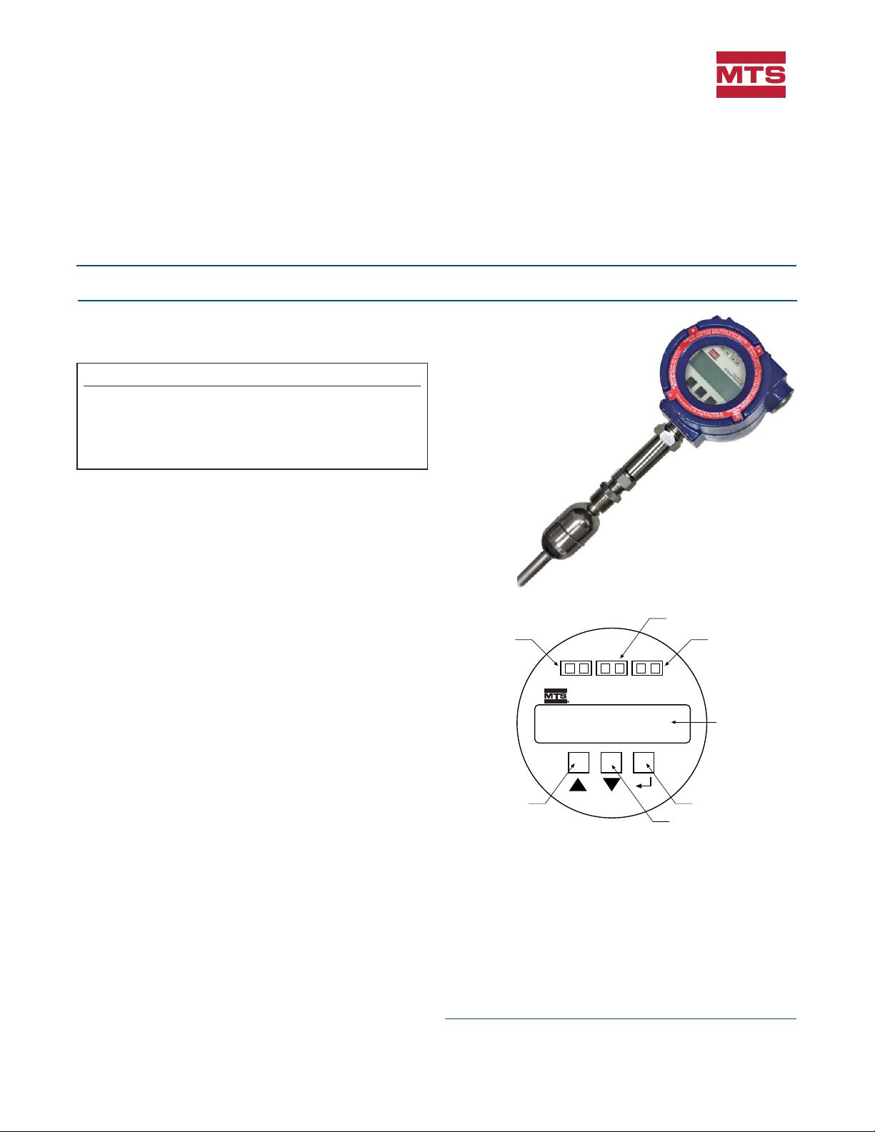
Loop 1 test port
Up Key
Loop 1 Test
+ —
T
O
R
E
M
O
V
E
E
L
E
C
T
R
O
N
I
C
S
M
O
D
U
Model MR Rigid Transmitter
Single-Cavity Housing
HART test port
Loop 2 Test
HART
+ —
Level Plus
M-Series Transmitter
O
N
O
D
-
N
O
L
E
,
P
U
L
L
U
N
I
T
I
N
U
I
T
C
E
R
I
D
D
R
A
W
P
Down Key
®
T
T
Loop 2 test port
Custom LCD Display
N
R
U
T
R
O
T
S
I
W
Enter Key
All specifications are subject to change. Contact MTS for specifications and
engineering drawings that are critical to your application. Drawings contained
in this document are for reference only. Go to http://www.mtssensors.com for
the latest support documentation and related media.
Page 2
FM
APPROVED
Part Number: 550731 Revision E, 09/03. 05/12
MTS, Temposonics and Level Plus are registered trademarks of MTS Systems Corporation.
All other trademarks are the property of their respective owners.
All Temposonics sensors are covered by US patent number 5,545,984. Additional patents are pending.
Printed in USA. Copyright © 2012 MTS Systems Corporation. All Rights Reserved in all media.
SENSORS
MTS Systems Corporation
Sensors Division
®
3001 Sheldon Drive
Cary, North Carolina
27513, USA
Tel.: +1-800-633-7609
Fax: +1-919-677-2343
+1-800-498-4442
MTS Sensor Technologie
GmbH & Co. KG
Auf dem Schüffel 9
D - 58513 Lüdenscheid, Germany
Tel.: +49-2351-9587-0
Fax: +49-2351-56491
e-mail: info@mtssensor.de
http://www.mtssensor.de
MTS Sensors Technology
Corporation
737 Aihara-cho, Machida-shi
Tokyo 194-0211, Japan
Tel.: +81-42-775-3838
Fax: +81-42-775-5516
e-mail: info@mtssensor.co.jp
http://www.mtssensor.co.jp
e-mail: sensorsinfo@mts.com
http://www.mtssensors.com
 Loading...