

Page 1

Series 111 Accumulator
Product Information
Model 111.11
Model 111.12
l
011-553-304 B
Page 2

Copyright information
Trademark information
© 2000 MTS Systems Corporation. All rights reserved.
MTS is a registered trademark of MTS Systems Corporation.
Contact information
MTS Systems Corporation
14000 Technology Drive
Eden Prairie, Minnesota 55344-2290 USA
Toll Free Phone: 800-328-2255 (within the U.S. or Canada)
Phone: 612-937-4000 (outside the U.S. or Canada)
Fax: 612-937-4515
E-mail: info@mts.com
http://www.mts.com
Publication information ISO 9001 Certified
M
ANUAL
P
115533-00A December 1982
115533-01A August 1983
115533-02A September 1984
115533-03A June 1987
115533-03B February 1988
115533-03C February 1989
115533-03D June 1990
115533-03E November 1991
ART
N
UMBER
P
UBLICATION
D
ATE
115533-03F July 1993
115533-03G June 1994
115533-04A June 1998
011-553-304 B June 1999
Page 3

Contents
Introduction 5
Functional Description 6
Specifications 7
Installation 9
Maintenance 11
Checking the Accumulator Precharge 13
Changing the Precharge Pressure 15
Purging Fluid from the Gas Chamber 17
Removing the Accumulator 18
Replacing the Accumulator Seal 19
Series 111 Accumulators Contents
3
Page 4

4
Series 111 Accumulators
Page 5
Introduction
The Series 111 Accumulator stabilize the hydraulic lines in your system.
There are two models availlable:
• The Model 111.11B Accumulator is a boss port-mounted accumulator
that requires a boss adapter fitting for mounting.
• The Model 111.12C Accumulator is bolt-mounted to a flange and
typically has a larger nitrogen gas capacity than the Model 111.11B.
Contents
Functional Description 6
Specifications 7
What you need to
know
Series 111 Accumulators Introduction
MTS Systems Corporation assumes that you know how to use your
controller. See the appropriate manual for information about performing
any controller-related step in this manual’s procedures. You are expected
to know how to perform the following procedures:
• Turning hydraulic pressure on and off
• Selecting a control mode
• Manually adjusting the actuator position
5
Page 6
Functional Description
The MTS Series 111 Accumulators can reduce fluctuations hydraulic lines
due to sudden changes in hydraulic flow rate. They also act a short term
energy source for high-rate tests by providing additional hydraulic flow for
short periods to meet irregular peak demands. Like a capacitor,
accumulators filter out pulses in the hydraulic fluid to provide steady
hydraulic pressure.
Accumulators are like a hydraulic
version of a capacitor. They are
hydro-pneumatic devices located at
strategic points in a hydraulic
system. They may be connected to
the pressure line and to the return
line.
Nitrogen
Side
Accumulators are precharged with
pressure. Precharge pressure is the
pressure of the compressed gas
(usually nitrogen) before hydraulic
fluid is introduced.
Inserting accumulators into the
hydraulic lines permits some fluid to
be stored under pressure a short
distance from the servovalve and
actuator. This has the effect of
keeping fluid in the lines in motion
and reducing the inertia and line
restriction considerations. When the
servovalve opens and line pressure begins to drop, the accumulator in the
hydraulic service manifold (HSM) immediately supplies part of the fluid
volume and maintains the line pressure. Then, when the servovalve closes,
the hydraulic power supply (HPS) recharges the accumulator , causing fluid
in the lines to remain in motion.
The pattern and frequency of the signal that drives the servovalve will have
considerable effect on the HSM accumulator efficiency. Square wave
signals, for example, cause a greater demand than sine wave signals or
ramp signals.
Piston
Fluid
Side
Hydraulic Fluid
Accumulator
6
Introduction
At some frequencies, fluid flow in the lines may stop completely, and
overcoming the fluid inertia may become a more significant operational
factor.
An accumulator in the return line damps the pulsing effect caused by
“slugs” of fluid being injected into the line as the actuator moves.
Movement of hoses and/or hammering of hard lines is also reduced.
Series 111 Accumulators
Page 7

Specifications
The tables shown here list the specifications for the Series 111
Accumulators.
PECIFICATIONS
S
P
ARAMETER
Minimum burst pressure 83 MPa (12,000 psi) 138 MPa (20,000 psi)
Rated fatigue pressure 21 MPa (3000 psi) 22 MPa (3200 psi)
Operating temperature –40°C to 93.3°C (–40°F to 200°F)
M
ODEL
111.11B M
ODEL
111.12C
Hydraulic fluid
Petroleum-based hydraulic fluid. Contact MTS for
use with other fluids.
Charge gas
Dry nitrogen
Note Specifications are subject to change without notice. Contact MTS
Systems Corporation for verification of specifications critical to your
needs.
Capacity, Dimension, and Weight
†
A
ODEL
M
111.11B-01
111.11B-02
111.11B-03
111.11B-04
111.12C-02
*
N
AS
G
82 cm
164 cm
475 cm
950 cm
950 cm
ITROGEN
APACITY
C
3
5 in.
3
10 in.
3
1 pt 27.94 11.0 7.87 3.1 6.35 2.5 16 SAE (1-5/16-12 UNF-2B) 5.94 13.1
3
1 qt 42.88 16.9 7.87 3.1 6.35 2.5 20 SAE (1-5/8-12 UNF-2B) 7.98 17.6
3
1 qt 29.51 11.6 12.7 5.0 10.16 4.0
cm in cm in cm in
3
15.54 6.12 7.87 3.1 6.35 2.5 12 SAE (1-1/16-12 UNF-2B) 4.26 9.4
3
18.08 7.12 7.87 3.1 6.35 2.5 12 SAE (1-1/16-12 UNF-2B) 4.63 10.2
ENGTH
L
†
111.12C-03 1.9 l 0.5 gal 39.07 15.4 12.7 5.0 10.16 4.0
†
B
H
YDRAULIC
ORT
P
F
ONNECTION
C
LUID
1-1/2 SAE 4-bolt flange
1-1/2 SAE 4-bolt flange
‡
‡
M
AXP
KG LBS
18.45 40.6
21.77 48.0
111.12C-04 3.8 l 1 gal 61.93 24.4 12.7 5.0 10.16 4.0
1-1/2 SAE 4-bolt flange
‡
29.87 65.8
* The models listed in this table are considered standard models. Other models may be
manufactured with different capacities, lengths, or hydraulic fluid port connections than listed
here. Contact MTS Systems Corporation for information on nonstandard models.
† See the figures on the next page.
‡ Standard pressure series (Code 61).
Series 111 Accumulators Introduction
7
Page 8

Ref.
1.563 in.
(39.7 mm)
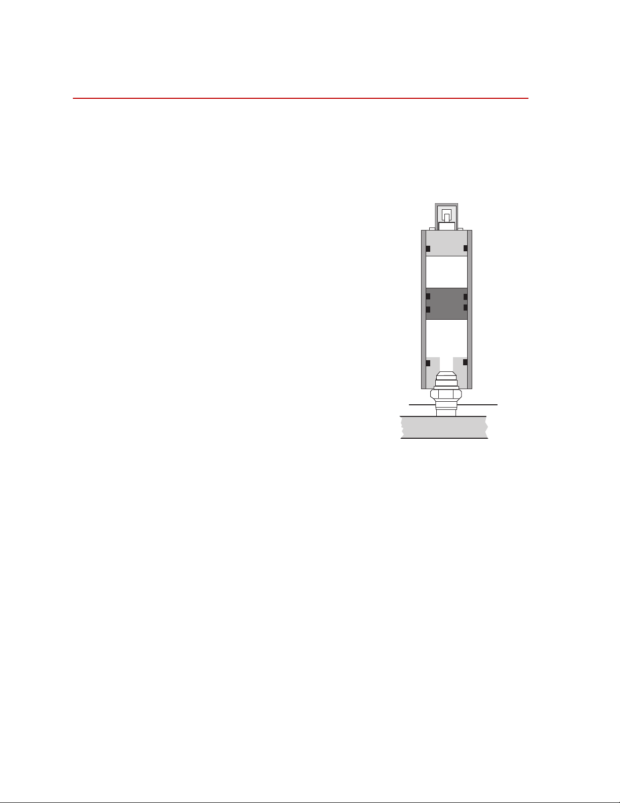
The cross-section figures shown on this page illustrate the difference
between the accumulator models.
Typical Boss
Adapter Fitting
Length
B
A
Accumulator
Valv e Assembly
Protective Cover
Ref.
1.563 in.
(39.7 mm)
Accumulator
Valve A ssembly
Protective Cover
Relief V ent
Model 111.11B Accumulator Cross-section
Length
A
B
Relief V ent
Hydraulic
Fluid Port
Hydraulic
Fluid Port
Ref.
1.406 in.
(35.7 mm)
Locking Pin
Locking Pin
Ref.
0.703 in.
(17.8 mm)
2.750 in.
(69.9 mm)
Ref.
1.375 in.
(34.9 mm)
1/2-13 UNC-2B
Ref.
8
Introduction
Model 111.12C Accumulator Cross-section
Series 111 Accumulators
Page 9
Installation
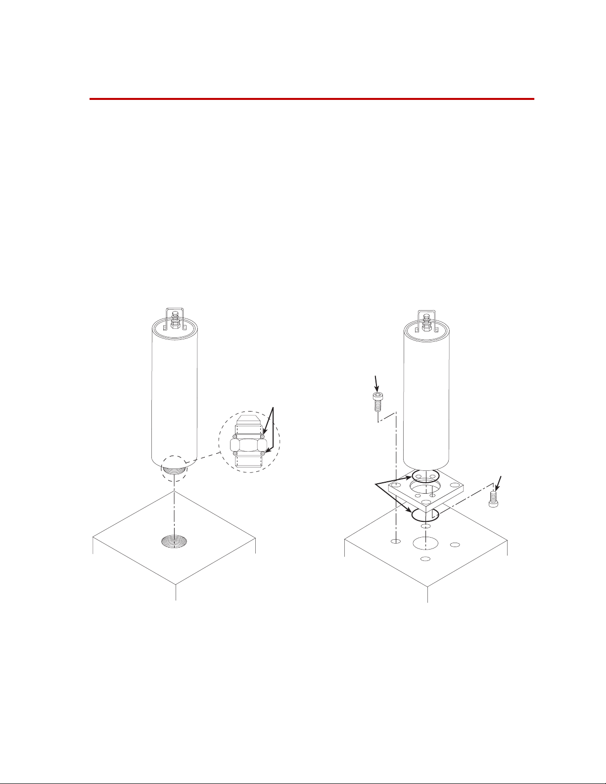
There are two models of the Series 111 Accumulator. The following figure
shows the typical mounting configuration for the Models 111.11B and
111.12C Accumulators.
• The Model 111.11B Accumulator is mounted with a boss adapter
fitting and O-ring seals. When the accumulator is ordered as a
component, the boss adapter and O-ring seals are not included with
the accumulator, they must be purchased separately.
• The Model 111.12C Accumulator is flush mounted with four bolts and
O-ring seal(s). When the accumulator is ordered as a component, the
four bolts (grade-8) and O-ring seal(s) (max. size 54.28 mm [2.137 in.]
outside diameter, 47.22 mm [1.859 in.] inside diameter), are not
included with the accumulator and must be purchased separately.
111.11B
Boss Adapter
Mounting
O-Rings
Flange
Mounting
O-Rings
Mounting Configurations
Flange
Mounting
Bolt
111.12C
Accumulator
Mounting
3
1
2
4
Bolts (4)
Required equipment
The following equipment is required for accumulator installation:
• Open-end wrench and strap wrench (for the Model 111.11B)
• Hex key set and torque wrench (for the Model 111.12C)
Series 111 Accumulators Installation
9
Page 10

Note When installing a replacement accumulator into an existing system, the
replacement accumulator should be precharged to the same pressure
level as the accumulator being removed. Be sure that this precharge
level is recorded on the label of the replacement accumulator.
Procedure
Complete the following steps to mount the accumulator. See the figure on
page 9 to complete the following procedure.
1. Mount the accumulator in the system after lubricating the mounting
O-ring seal(s). Note the O-ring seal configuration.
• For the Model 111.11B Accumulator
Thread the unit onto the boss adapter fitting and securely tighten
it with a strap wrench.
• For the Model 111.12C Accumulator
Lubricate and torque the four mounting bolts in increments
(according to the pattern shown in the “Mounting Configurations”
on page 9 figure) to a final torque of 108 N-m (80 lbf-ft).
2. Check the accumulator precharge pressure as described in “Checking
the Accumulator Precharge” on page 13.
10
Installation
Series 111 Accumulators
Page 11
Maintenance
This section describes how to maintain the charge in the accumulator.
Contents
Maintenance
guidelines
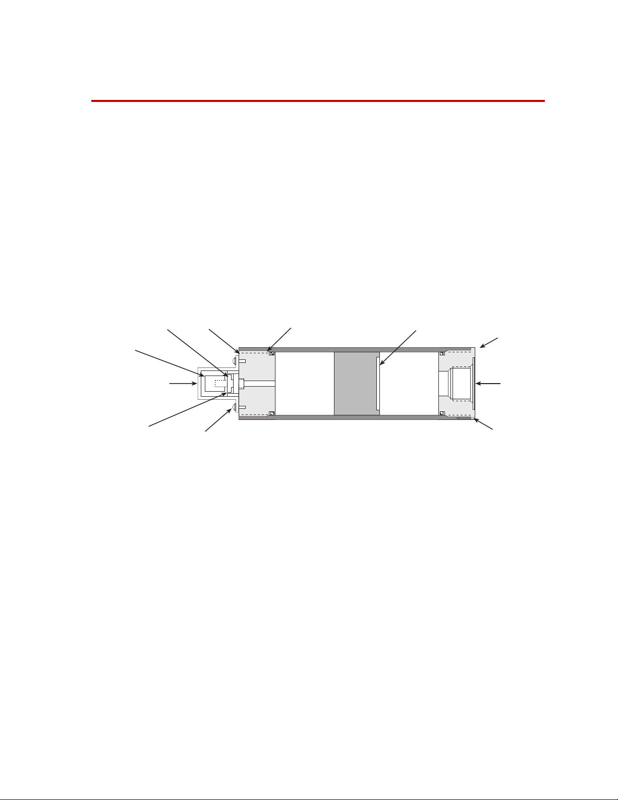
Locknut End Cap Chamfer Piston
Valve
Stem Cap
Accumulator V alve
Protective Cover
Accumulator
Valv e Assembly
Screws
Checking the Accumulator Precharge 13
Changing the Precharge Pressure 15
Purging Fluid from the Gas Chamber 17
Removing the Accumulator 18
Replacing the Accumulator Seal 19
Maintaining the proper pressure level for your accumulators is essential for
optimum system performance and component life. Review the following
figure to familiarize yourself with the accumulator components and their
locations. Also review the guidelines on the following page before
performing any procedure.
Hydraulic Fluid
End Cap
Hydraulic
Fluid Port
Locking Pin
Accumulator Components
Use the following guidelines to determine when maintenance is required.
• Check the precharge pressure at periodic intervals. The length of time
between checks depends on how the system is used. Some factors to
consider when establishing this time interval are operating frequency,
displacement, and duration. Start with one month intervals until you
determine another interval is more appropriate. See “Checking the
Accumulator Precharge” on page 13 for more information.
• Maintain a log book on the condition of the precharge at each check.
Use this data to determine if the time between checks should be
increased or decreased and if maintenance is required.
Series 111 Accumulators Maintenance
11
Page 12

• Because the precharge pressure level varies with a temperature
change, the level should always be checked at the same temperature.
If it is not, use one of the following formulas to determine if the
precharge level is acceptable.
Degrees Fahrenheit:
460 current temperatrure()+
current pressure original pressure
Degrees Celsius:
current pressure original pressure
---------------------------------------------------------------------
×=
460 original temperature()+
273 current temperatrure()+
---------------------------------------------------------------------
×=
273 original temperature()+
• If a pressure line accumulator has a pressure level change of ±1.4 MPa
(200 psi) between checks, the accumulator requires maintenance or
the time interval between checks needs to be shortened.
• If a return line accumulator has a change of ±50% of the original
pressure level between checks, the accumulator requires maintenance
or the time interval between checks needs to be shortened.
• If the precharge pressure level increases at each check interval, this
indicates that fluid is collecting on the gas side (a small amount of
fluid leakage is normal). When the precharge pressure level cannot be
maintained within the limits, remove the fluid and charge the
accumulator. If the levels are again exceeded at the first check interval,
replace the piston seals after the initial fluid has been changed.
• If the precharge pressure level decreases at each check interval, this
indicates gas leakage to the fluid side. When the precharge pressure
level cannot be maintained within the limits stated in the previous
guidelines, replace the accumulator piston seals.
• During normal operation, the accumulator piston should be near the
center of the accumulator cylinder. To check the approximate piston
location, note the warm-to-hot transition point on the accumulator
cylinder wall during operation. If the piston is near the charging stem
end, the accumulator may need charging. If the piston is at the other
end, the accumulator may have an excess charge, or more likely an
excessive amount of hydraulic fluid has collected in the gas chamber.
12
Maintenance
Series 111 Accumulators
Page 13
Checking the Accumulator Precharge
Special equipment
Procedure
WARNING
The following equipment is for any Series 111 Accumulator:
• Accumulator charging kit (MTS part number 376986-01)
To check your accumulator precharge, perform the following:
Accumulators are pressurized devices.
Pressurized accumulators and their parts can become lethal projectiles if
disassembled and can cause death to persons and/or damage to
equipment.
Do not remove an accumulator that is pressurized. Completely remove hydraulic
pressure and discharge the accumulator before any parts, except the protective
cover and valve stem cap are removed.
1. Ensure that system hydraulic pressure has been reduced to zero before
proceeding. To do this, turn off the hydraulic power unit and exercise
the actuator until it stops moving.
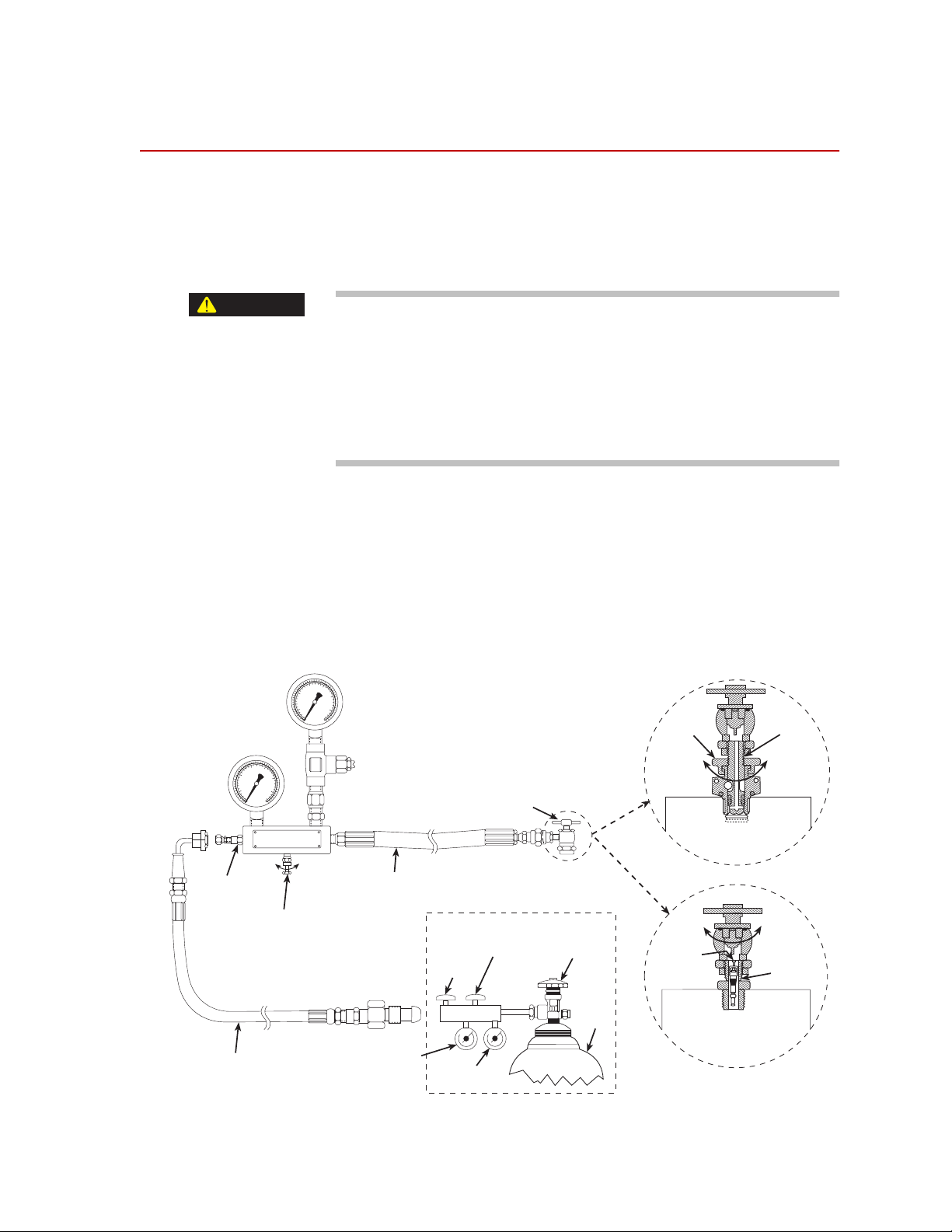
2. Close the bleed valve on the accumulator charging kit. Remove the
protective cover and valve stem cap from the accumulator (see
“Accumulator Components” on page 11 and the figure below).
3. Go to the appropriate procedure on the next page.
Low Pressure Gage
0-300 psi (0-2.1 MPa)
High Pressure Gage
0-3000 psi (0-21 MPa)
r
Open
Input
Check Valve
Nitrogen Supply Hose
Accumulator Charging Kit
Bleed Valve
Close
Gage Protector
(factory set to limit
pressure to the gage
to approximately
200 psi (1.4 MPa)
Extension Hose
Regulator Output
Pressure Gage
Chuck Valve
THESE ITEMS SUPPLIED BY USER
Regulator Output
Pressure Valve
Regulator
Shut-Off Valve
Nitrogen Bottle
Pressure Gage
Nitrogen
Bottle Valv e
Nitrogen
Bottle
Locknut
Close
Open
Valve Core
Poppet T ype
Accumulator Valve
To Open and Close
Use Locknut
OR
Core Type
Accumulator Valve
To Open and Close
Use Chuck Valve
Valve Stem
Open
Close
Valve Stem
Series 111 Accumulators Maintenance
13
Page 14

Checking the Series 111 Accumulator Precharge
The Series 111 Accumulators use the poppet-type valve (as shown on the
previous page).
1. Connect the charging kit chuck valve to the accumulator valve stem.
2. With an open-end wrench, turn the locknut counterclockwise on the
accumulator valve assembly to open the valve. Read the pressure on
either the high or low accumulator charging kit pressure gage.
• If the pressure reading is other than the required pressure level
recorded on the accumulator, go to the procedure “Changing the
Precharge Pressure” on page 15.
• If the pressure level corresponds to the level recorded on the
accumulator label, turn the locknut clockwise to close the valve
and continue this procedure.
3. Open the bleed valve on the accumulator charging kit and remove the
chuck valve from the accumulator. Replace the valve stem cap and
protective cover on the accumulator.
Checking a Non-MTS Accumulator Precharge
Non-MTS accumulators typically use either a poppet type valve or a core
type valve (as shown on the previous page).
1. Determine which type of gas pressure valve is present on the
accumulator and connect the charging kit chuck valve to the
accumulator valve stem.
2. Open the locknut (poppet-type) or chuck valve (core-type).
Note The poppet-type valve opens by turning the locknut counterclockwise
and closes by turning the locknut clockwise. To open a core type valve,
attach a chuck valve to the valve stem and turn the chuck valve handle
clockwise to depress the valve core. Close the valve by turning the
handle counterclockwise.
3. Read the pressure on either the high or low accumulator charging kit
pressure gage. The low pressure gage is limited to approximately 1.4
MPa (200 psi) by the gage protector.
• If the pressure reading is other than the required pressure level
recorded on the accumulator, go to the procedure “Changing the
Precharge Pressure” on page 15.
• If the pressure level corresponds to the level recorded on the
accumulator label, close the locknut (poppet-type) or close the
chuck valve (core-type). Continue to Step 4.
14
Maintenance
4. Open the bleed valve on the accumulator charging kit and remove the
chuck valve from the accumulator. Replace the valve stem cap and
protective cover on the accumulator.
Series 111 Accumulators
Page 15

Changing the Precharge Pressure
Often the precharge of an accumulator mounted on a hydraulic supply line
is increased to enhance system performance and reduce the transient HPS
flow demands. Accumulators may be precharged to 10 MPa (1500 psi) or
more, although amounts above 14 MPa (2200 psi) will have less and less
performance effect in most situations. Be sure that you read the following
warning before you charge your accumulator.
WARNING
Accumulators have specific pressure ratings.
If the precharge pressure is too high, the accumulator can bottom out
causing the release of metal particles into the hydraulic fluid. Charging
accumulators above their rated level can damage system equipment.
Do not charge accumulators to pressures above their rated level. Charge
accumulators below their rated fatigue pressure of 21 MPa (3000 psi) for the
Model 111.11B and 22 MPa (3200 psi) for the Model 111.12C. Use a suitable
regulator and gage set to an accumulator’s charges.
Before you begin Go to “Checking the Accumulator Precharge” on page 13 to determine if
you need to change the precharge pressure.
Decreasing pressure Complete the following steps to decrease the precharge pressure.
1. Slowly open the bleed valve on the accumulator charging kit until gas
begins to escape. When the pressure reading on the appropriate
pressure gage drops to the level required, close the bleed valve.
2. Close the locknut (or close the chuck valve if you have a core-type
valve). Open the bleed valve on the accumulator charging kit and
remove the chuck valve from the accumulator.
3. Install the valve stem cap and protective cover.
Increasing pressure Complete the following steps to increase the precharge pressure.
1. Close the locknut on the accumulator (or close the chuck valve for a
core-type valve).
2. Open the bleed valve two turns.
WARNING
Series 111 Accumulators Maintenance
Mixing gases can produce unpredictable results.
Do not use another gas to precharge an accumulator.
Use only dry nitrogen gas to precharge accumulators.
3. Connect the nitrogen supply hose from the supply bottle pressure
regulator output to the input check valve on the charging kit.
15
Page 16

4. Open the nitrogen bottle valve. Check the nitrogen bottle pressure
gage on the regulator. (The bottle must contain sufficient pressure to
provide an adequate gas volume.)
5. Monitor the regulator output pressure gage and adjust the regulator
output pressure valve to the required level.
CAUTION
Avoid rapid and extreme pressure transitions.
Rapid flow rates with pressure differentials of more than 2.1 MPa (300 psi)
across the input check valve can damage the valve seal(s).
Do not allow rapid flow rates. Open the regulator shut-of f valv e only f ar enough to
permit a gradual transfer of gas.
6. Slowly open the regulator shut-off valve until gas is heard escaping
from the accumulator charging kit bleed valve. Allow gas to slowly
escape for approximately ten seconds, then close the bleed valve.
Immediately close the regulator shut-off valve before the pressure
reading on either the high or low charging kit pressure gage exceeds
the pressure level of the accumulator.
7. Open the locknut (or open the chuck valve for a core-type valve).
Slowly open the regulator shut-off valve until the pressure indicator on
either the high or low charging kit pressure gage begins to rise. When
the pressure is at the required pressure level (recorded on the
accumulator), close the regulator shut-off valve.
8. Close the locknut (or close the chuck valve for a core type valve).
9. Open the bleed valve on the accumulator charging kit and remove the
chuck valve from the accumulator.
10. Install the valve stem cap and protective cover. Close the valve on the
nitrogen bottle.
16
Maintenance
Series 111 Accumulators
Page 17

Purging Fluid from the Gas Chamber
When you should
perform this
procedure
CAUTION
Procedure Complete the following steps to purge the fluid from the gas chamber. See
Piston-type accumulators may collect hydraulic fluid in the gas chamber,
which then reduces the gas volume of the accumulator. The fluid should
be purged from the gas side if a pressure check procedure shows one or
more of the following:
• A consistent trend of pressure being higher than expected.
• Precharging requires smaller volumes of gas than expected to obtain a
desired pressure level.
• Fluid is expelled from a gas valve during gas venting.
Venting pressurized gasses can generate loud noises and freezing
temperatures.
Transferring gasses from high to low pressure containers creates freezing
temperatures.
Do not work with pressurized gasses without wearing protective clothing. Wear
heavy gloves, saf ety glasses, and ear plugs when working with pressuriz ed gases
“Accumulator Components” on page 11.
1. If the valve stem of the accumulator is facing down, go directly to
step 2.
If the valve stem of the accumulator is facing up or the accumulator is
on its side, remove the accumulator as described in “Removing the
Accumulator” on page 18 and turn it so the valve stem is facing down.
2. Remove the accumulator valve protective cover and the valve stem
cap. Securely position the accumulator with the gas valve down.
3. Place a suitable container under the valve stem to capture any
expelled fluid. Use an open-end wrench and open the locknut on the
accumulator valve assembly two or three full turns. Allow gas
pressure to reduce to zero and hydraulic fluid to expel.
4. Replace the accumulator as described in “Installation” on page 9. Then
precharge the accumulator as described in “Changing the Precharge
Pressure” on page 15.
Series 111 Accumulators Maintenance
17
Page 18

Removing the Accumulator
Perform the following steps to remove the accumulator.
WARNING
Accumulators are pressurized devices.
Pressurized accumulators and their parts can become lethal projectiles if
disassembled and can cause death to persons and/or damage to
equipment.
Do not remove an accumulator that is pressurized. Completely remove hydraulic
pressure and discharge the accumulator before any parts, except the protective
cover and valve stem cap are removed.
1. Ensure that system hydraulic pressure has been reduced to zero before
proceeding. To do this, turn off the hydraulic power unit and exercise
the actuator until it stops moving.
2. Place a drain pan under the accumulator to be removed.
3. To prevent contamination of the hydraulic fluid, cover any ports that
are exposed.
4. If you have the Model 111.12C Accumulator, use a hex key to remove
the flange and accumulator mounting bolts (see “Accumulator
Components” on page 11).
If you have the Model 111.11B Accumulator, use an open-end and
strap wrench to loosen the accumulator from the boss adapter fitting.
5. Perform any required maintenance (see the other procedures in this
section).
6. To reinstall the accumulator, use the procedure in “Installation” on
page 9.
18
Maintenance
Series 111 Accumulators
Page 19

Replacing the Accumulator Seal
Special equipment The following equipment is required to replace any Series 111 Accumulator
seals:
• A seal kit (MTS part number 041-463-501 for the Model 111.11B or
MTS part number 041-463-301 for the Model 111.12C)
• Accumulator charging kit (MTS part number 376986-01)
Procedure Use the following procedure to replace any Series 111 Accumulator seals:
1. Remove the accumulator as described in “Removing the Accumulator”
on page 18.
2. Remove the accumulator valve protective cover and the valve stem
cap. Securely position the accumulator with the gas valve down.
3. Place a suitable container under the valve stem to capture any
expelled fluid. Use an open-end wrench and open the locknut on the
accumulator valve assembly two or three full turns. Allow gas
pressure to reduce to zero and any hydraulic fluid to be expelled.
4. Use an open-end wrench and remove the accumulator valve assembly
from the end cap. To remove the end cap, hold the accumulator body
with a strap wrench, insert the spanner wrench pins into the screw
holes in the end cap, and rotate the wrench counterclockwise.
Locknut End Cap Chamfer Piston
Valve Stem Cap
Accumulator V alve
Protective
Cover
Accumulator
Valv e Assembly
Backup
Ring
Detail A Detail B Detail C
Seal
5. Insert an aluminum or wooden rod into the hydraulic fluid port
opening (you may have to remove the boss adapter fitting from the
hydraulic fluid port of Model 111.11B Accumulators) until it contacts
the piston. Push the piston out of the cylinder.
Hydraulic Fluid
Screws
A
Piston Seals
B
Piston Wear
Strip
Seal
C
Backup
Accumulator Seal Details
End Cap
Hydraulic
Fluid Port
Locking Pin
Ring
Series 111 Accumulators Maintenance
19
Page 20

6. See “Accumulator Seal Details” on page 19 for details A and B for this
step. Remove the end cap backup ring and seal (detail A), and the
piston seals and wear strip (detail B). Clean the cylinder with a soft
cloth and inspect the piston and inner walls for scratches. If the inner
walls of the cylinder are scratched to the extent that the piston seals
cannot seal properly, replace the entire accumulator.
7. Install a new piston seals, wear strip, new seal, and backup ring on
the end cap.
8. Apply a small amount of clean hydraulic fluid to the piston seals and
piston wear strip. Gently insert the piston into the cylinder with the
piston wear strip turned toward the hydraulic fluid port end, taking
care not to pinch the piston seals against the chamfered surface of the
cylinder. Ensure that the piston is aligned within the cylinder. Firmly
push the piston 2 to 3 inches (5 to 7 cm) into the cylinder.
9. Apply a small amount of clean hydraulic fluid to the end cap seal and
backup ring. Turn the end cap into the cylinder until the threads are
engaged.
Note Do not overtighten the end cap.Tightening the end cap with extreme
force does not improve the seal and can damage the cap and/or cylinder
threads.Tighten the end cap using the following steps.
10. Hold the accumulator body with a strap wrench and use a pin spanner
wrench to rotate the end cap clockwise until the outer cap surface is
almost flush with the end of the cylinder and resistance indicates that
the cap and cylinder chamfer surfaces have met.
11. Thread the accumulator valve assembly into the end cap port. Use an
open-end wrench and tighten the valve assembly until the underside
of the hexagonal flange contacts the outer end cap surface.
12. Check the condition of the mounting O-rings on the boss adapter
fitting (Model 111.11B) or the flange mounting O-rings (Model
111.12C). If damaged, replace with new seals from the accumulator
seal kit.
20
Maintenance
Series 111 Accumulators
 Loading...