

MTS Sensors Temposonics T Operation Manual
TH Analog ATEX / IECEx / CEC / NEC / KCs / EAC Ex certied / Japanese approval /
Safety SIL 2 capable
Operation Manual
Temposonics
®
Magnetostrictive Linear Position Sensors

2
Temposonics® TH Analog ATEX / IECEx / CEC / NEC / KCs / EAC Ex certied / Japanese approval / Safety SIL 2 capable
Operation Manual
Table of contents
1. Introduction .......................................................................................................................................................3
1.1 Purpose and use of this manual .................................................................................................................................................................... 3
1.2 Used symbols and warnings .........................................................................................................................................................................3
2. Safety instructions ...............................................................................................................................................3
2.1 Intended use ..................................................................................................................................................................................................3
2.2 Forseeable misuse .........................................................................................................................................................................................4
2.3 Installation, commissioning and operation ....................................................................................................................................................4
2.4 Safety instructions for use in explosion-hazardous areas .............................................................................................................................5
2.5 Warranty........................................................................................................................................................................................................6
2.6 Return ........................................................................................................................................................................................................... 6
3. Identification......................................................................................................................................................7
3.1 Order code of Temposonics
®
TH ....................................................................................................................................................................7
3.2 Nameplate (example) ....................................................................................................................................................................................9
3.3 Approvals ...................................................................................................................................................................................................... 9
3.4 Scope of delivery ........................................................................................................................................................................................... 9
4. Product description and commissioning ................................................................................................................... 10
4.1 Functionality and system design .................................................................................................................................................................10
4.2 Styles and installation of Temposonics
®
TH ................................................................................................................................................ 11
4.3 Magnet installation ...................................................................................................................................................................................... 17
4.4 Electrical connection ...................................................................................................................................................................................19
4.5 Frequently ordered accessories .................................................................................................................................................................. 25
5. Operation........................................................................................................................................................ 28
5.1 Getting started .............................................................................................................................................................................................28
5.2 Programming and configuration .................................................................................................................................................................28
6. Maintenance and troubleshooting .......................................................................................................................... 35
6.1 Error conditions, troubleshooting ................................................................................................................................................................35
6.2 Maintenance ................................................................................................................................................................................................ 35
6.3 Repair ..........................................................................................................................................................................................................35
6.4 List of spare parts .......................................................................................................................................................................................35
6.5 Transport and storage .................................................................................................................................................................................35
7. Removal from service / dismantling ........................................................................................................................ 35
8. Technical data Temposonics
®
TH SIL 2 ..................................................................................................................... 36
9. Technical data Temposonics
®
TH standard ................................................................................................................ 39
10. Declaration of conformity of standard version ........................................................................................................... 41
11. Declaration of conformity of SIL 2 version ............................................................................................................... 42
12. Appendix ....................................................................................................................................................... 43
3
Temposonics® TH Analog ATEX / IECEx / CEC / NEC / KCs / EAC Ex certied / Japanese approval / Safety SIL 2 capable
Operation Manual
1/ The term qualied technical personnel characterizes persons who:
• are familiar with the safety concepts of automation technology applicable to the
particular project
• are competent in the eld of electromagnetic compatibility (EMC)
• have received adequate training for commissioning and service operations
• are familiar with the operation of the device and know the information required
for correct operation provided in the product documentation
1. Introduction
1.1 Purpose and use of this manual
Before starting the operation of Temposonics® position sensors,
read this documentation thoroughly and follow the safety
information. For further details on SIL 2 refer to MTS Sensors
SIL 2 safety manual (part number: 551504). Keep the manual for
future reference!
The content of this technical documentation and of its appendix is
intended to provide information on mounting, installation and commissioning by qualied automation personnel
1
or instructed service
technicians who are familiar with the project planning and dealing with
Temposonics
®
sensors.
1.2 Used symbols and warnings
Warnings are intended for your personal safety and for avoidance of
damage to the described product or connected devices. In this documentation, safety information and warnings to avoid dangers that
might affect the life and health of operating or service personnel or
cause material damage are highlighted by the preceding pictogram,
which is dened below.
Symbol Meaning
NOTICE
This symbol is used to point to situations
that may lead to material damage, but not to
personal injury.
2. Safety instructions
2.1 Intended use
This product must be used only for the applications dened under
item 1 to item 4 and only in conjunction with the third-party devices
and components recommended or approved by MTS Sensors. As a
prerequisite of proper and safe operation, the product requires correct
transport, storage, mounting and commissioning and must be operated with utmost care.
1. The sensor systems of all Temposonics
®
series are intended
exclusively for measurement tasks encountered in industrial,
commercial and laboratory applications. The sensors are considered as system accessories and must be connected to suitable
evaluation electronics, e.g. a PLC, IPC, indicator or other electronic control unit.
2. The sensor’s surface temperature class is T4.
3. The EU-Type Examination Certicates and Certicates of Compli-
ance have to be taken into account including any special condition
dened therein.
4. The position sensor may be used in zones (ATEX, IECEx) and
Classes, Zones and Divisions (CEC, NEC) according to chapter 8
and chapter 9. Any use of this product outside of these approved
areas will void the warranty and all manufacturer’s product responsibilities and liabilities. For non-hazardous areas MTS Sensors recommends to use the version N (not approved).
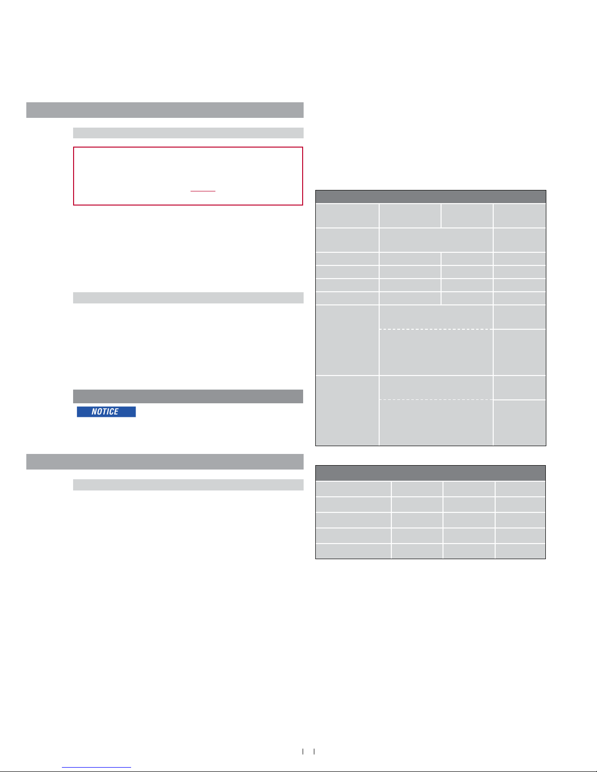
Class and Division Concept
Ex-Atmosphere Class Division Group
Gas-Ex Class I Div. 1 A*, B, C, D
Gas-Ex Class I Div. 2 A, B, C, D
Dust-Ex Class II/III Div. 1 E, F, G
Dust-Ex Class II/III Div. 2 E, F, G
*Cl. I Div. 1 Gr. A not valid for Canada
Zone Concept
Ex-Atmosphere Zone Category Explosion
group
Gas-Ex In the bafe between Zone 0 Up to IIC
(at the rod)
Gas-Ex Zone 1 2G IIA, IIB, IIC
Gas-Ex Zone 2 3G IIA, IIB, IIC
Dust-Ex Zone 21 2D IIIA, IIIB, IIIC
Dust-Ex Zone 22 3D IIIA, IIIB, IIIC
Gas-Ex In the bafe between Zone 0
and
Up to IIC
(at the rod)
Zone 1 or Zone 2 Up to IIC
(at the
connection
chamber)
Gas-Ex In the bafe between Zone 0
and
Up to IIC
(at the rod)
Dust-Ex Zone 21 or Zone 22 Up to IIIC
(at the
connection
chamber)
4
Temposonics® TH Analog ATEX / IECEx / CEC / NEC / KCs / EAC Ex certied / Japanese approval / Safety SIL 2 capable
Operation Manual
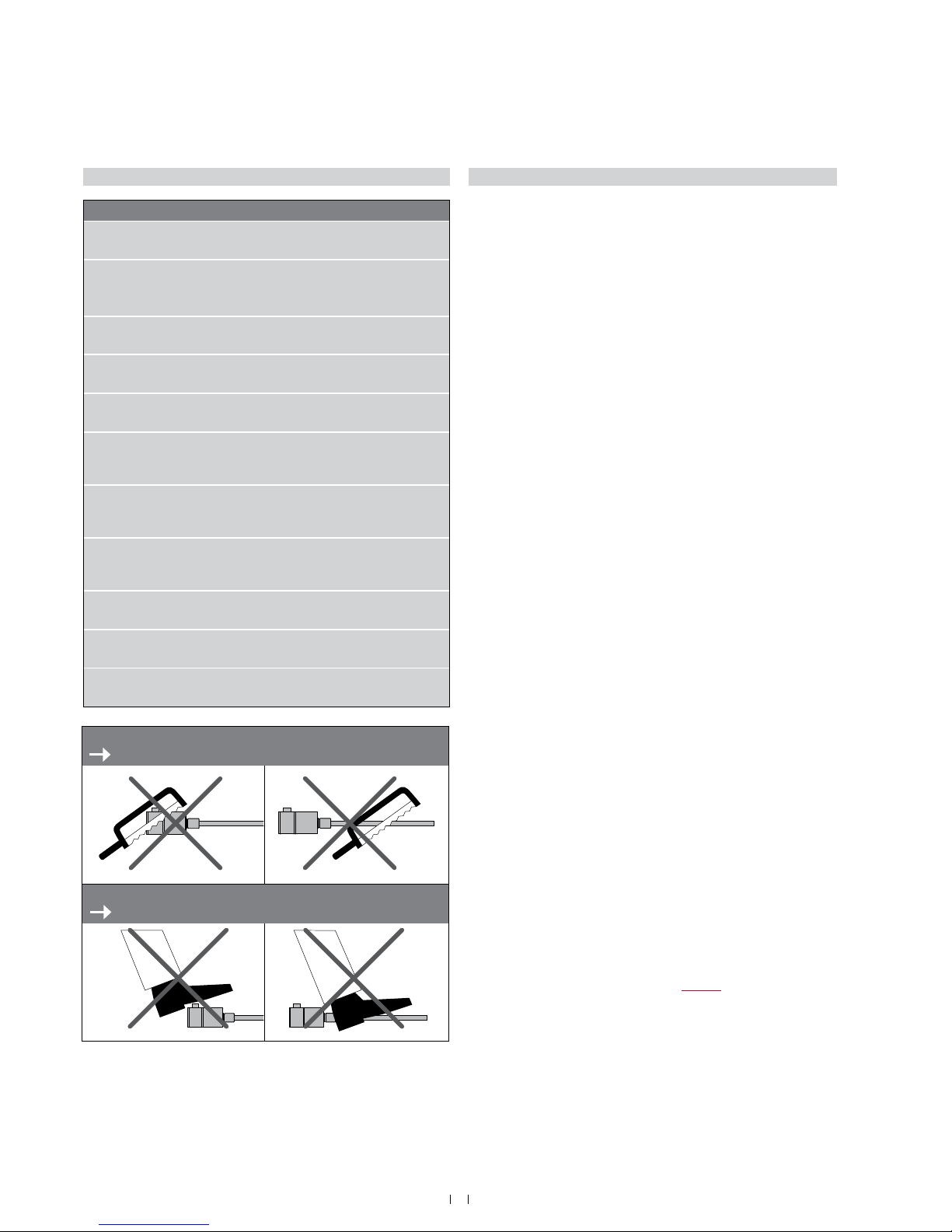
2.2 Forseeable misuse
Forseeable misuse Consequence
Lead compensating currents
through the enclosure
The sensor will be damaged
Use sensor without external fuse
in Zone 0 or as SIL 2 version (in
Zone 0, Zone 1 / 21)
In case of failure, the sensor
might overheat
Use a fuse with more than
125 mA
In case of failure, the sensor
might overheat
Wrong sensor connection The sensor will not work
properly or will be destroyed
Operate the sensor out of the
operating temperature range
No signal output
The sensor can be damaged
Power supply is out of the
dened range
Signal output is wrong /
no signal output /
the sensor will be damaged
Position measurement is
inuenced by an external
magnetic eld
Signal output is wrong
Cables are damaged Short circuit – the sensor can
be destroyed / sensor does not
respond
Spacers are missing /
are installed in a wrong order
Error in position measurement
Wrong connection
of ground / shield
Signal output is disturbed
The electronics can be damaged
Use of a magnet that is not
certied by MTS Sensors
Error in position measurement
Do not step on the sensor.
The sensor might be damaged.
Do not alter the sensor afterwards.
The sensor might be damaged.
2.3 Installation, commissioning and operation
The position sensors must be used only in technically safe condition. To maintain this condition and to ensure safe operation, installation, connection and service, work may be performed only by qualied
technical personnel, according to IEC 60079-14, TRBS 1203, Canadian Electrical Code (CEC) and National Electrical Code (NEC) and local
regulations.
If danger of injury to persons or of damage to operating equipment
is caused by sensor failure or malfunction, additional safety measures
such as plausibility checks, limit switches, EMERGENCY STOP
systems, protective devices etc. are required. In the event of trouble,
shut down the sensor and protect it against accidental operation.
Safety instructions for commissioning
To maintain the sensor’s operability, it is mandatory to follow the
instructions given below.
1. Follow the specications given in the technical data.
2. Ensure that equipment and associated components used in a
hazardous environment are selected and installed in compliance
with regulations governing the geographical location and facility.
Only install equipment that complies with the types of protection
relevant to the applicable Classes, Zones, Divisions and Groups.
3. In explosive atmospheres use only such auxiliary components
that meet all requirements of the local and national standards.
4. The potential equalisation of the system has to be established
according to the regulations of erection applicable in the
respective country of use (VDE 0100 part 540; IEC 364-5-54).
5. Sensors from MTS Sensors are approved only for the intended
use in industrial environments (see chapter “2.1 Intended use”
on page 3). Contact the manufacturer for advice if aggressive
substances are present in the sensor environment.
6. Measures for lightning protection have to be taken by the user.
7. The user is responsible for the mechanical protection of the
sensor.
8. The sensor may be used only for xed installations with
permanently wired cables. The user shall ensure that cables and
cable glands correspond to the risk assessment of the hazardous
application as well as to thermic, chemical and mechanical
environmental conditions. The user is also responsible for the
required strain relief. When selecting the sealing, the maximum
thermal load of the cables must be taken into account.
9. The user is responsible for meeting all safety conditions as
outlined by:
• Installation instructions
• Local prevailing standards and regulations
• Safety manual (document part no. 551504) for SIL 2 capable
sensor version
10. Any parts of the equipment which got stuck (e.g. by frost or
corrosion) may not be removed by force if potentially
explosive atmosphere is present.
11. The surface temperatures of equipment parts must be kept
clearly below the ignition temperature of the foreseeable air/
dust mixtures in order to prevent the ignition of suspended
dust.

5
Temposonics® TH Analog ATEX / IECEx / CEC / NEC / KCs / EAC Ex certied / Japanese approval / Safety SIL 2 capable
Operation Manual
How to ensure safe commissioning
1. Protect the sensor against mechanical damage during
installation and operation.
2. Do not use damaged products and secure them against unintentional commissioning. Mark damaged products as being
defective.
3. Prevent electrostatic charges.
4. Do not use the sensor in cathodic systems for corrosion
protection. Do not allow parasitic currents on the sensor housing.
5. Switch off the supply voltage prior to disconnecting or
connecting the connectors.
6. Connect the sensor very carefully and pay attention to the
polarity of connections, power supply as well as to the shape
and duration of control pulses.
7. Cable entry temperature and branching point temperature may
reach 104 °C (219 °F) and 116 °C (241 °F) respectively. Select
suitable cable and entry device.
8. For eld wiring, use cables suitable for the service temperature
range of −40 °C (−40 °F) to +116 °C (241 °F).
9. Do not open when energized. Open the sensor only as shown in
Fig. 7 on page 13.
10. A seal shall be installed within 18" of the enclosure (for NEC /
CEC only).
11. Use only approved power supplies of Category II according to
IEC 61010-1.
12. Ensure that the specied permissible limit values of the sensor
for operating voltage, environmental conditions, etc. are met.
13. Make sure that:
• the sensor and associated components were installed
according to the instructions
• the sensor enclosure is clean
• all screws (only those of quality 6.8, A2-50 or A4-50 are
allowed) are tightened according to specied fastening
torque in Fig. 7
• the cable glands certied according to the required
hazardous area classication and IP protection are tightened
according to the manufacture’s specications
• surfaces limiting the joint shall not be machined or painted
subsequently (ameproof enclosure)
• surfaces limiting the joint have not been provided with a seal
(ameproof enclosure)
• the magnet does not grind on the rod. This could cause
damage to the magnet and the sensor rod. If there is contact
between the moving magnet (including the magnet holder)
and the sensor rod, make sure that the maximum speed of the
moving magnet is less or equal 1 m/s.
14. Ground the sensor via one of the two ground lugs. Both the
sensor and the moving magnet including magnet holder must
be connected to protective ground (PE) to avoid electrostatic
discharge (ESD).
15. Before applying power, ensure that nobody’s safety is
jeopardized by starting machines.
16. Check the function of the sensor regularly and provide
documentation of the checks
(see chapter “6.2 Maintenance” on page 35).
2.4 Safety instructions for use in explosion-hazardous areas
The sensor has been designed for operation inside explosion-hazarded areas. It has been tested and left the factory in a condition in which
it is safe to operate. Relevant regulations and standards have been
observed. According to the marking (ATEX, IECEx, CEC, NEC, KCs,
EACEx, Japanese approval) the sensor is approved only for operation
in dened hazardous areas (see chapter “2.1 Intended use” on page
3). The SIL 2 version cannot be adjusted by the customer.
When do you need an external fuse?
How to install a T-Series sensor in Zone 0 according to the guidelines (ATEX, IECEx, CEC, NEC, EAC Ex, KCs Japanese approval)
1. Install an external fuse in compliance with IEC 127 outside the
Ex-atmosphere. Connect it upstream to the equipment.
Current: 125 mA
2. Install the sensor housing in Zone 1, Zone 2, Zone 21 or Zone 22.
Only the rod section (for version D, G, and E) can extend into
Zone 0.
3. Follow the safety regulations detailed in IEC/EN 60079-26,
ANSI/ISA 60079-26 (12.00.03), ANSI/ISA/IEC/EN 60079-10-1 and
JNIOSH-TR-46-2 to ensure isolation between Zone 0 and Zone 1.
4. When installing the TH sensor in the boundary wall for Zone 0,
the corresponding requirements in ANSI/ISA/IEC/EN 60079-26
and ANSI/ISA/IEC/EN 60079-10-1 have to be noticed. Thereby
the screw-in thread is to be sealed gas tightly (IP67) according to
ANSI/ISA/IEC/EN 60079-26 and ANSI/ISA/IEC/EN 60079-10-1.
Zone / Div. T-Series standard sensor T-Series SIL 2 sensor
Zone 0
(rod only)
External fuse required External fuse required
Zone 1 / 21 No additional fuse External fuse required
Zone 2 / 22 No additional fuse No additional fuse
Div. 1 External fuse
recommended
External fuse
recommended

6
Temposonics® TH Analog ATEX / IECEx / CEC / NEC / KCs / EAC Ex certied / Japanese approval / Safety SIL 2 capable
Operation Manual
2.5 Warranty
MTS Sensors grants a warranty period for the Temposonics
®
position sensors and supplied accessories relating to material
defects and faults that occur despite correct use in accordance with
the intended application
2
. The MTS Sensors obligation is limited to
repair or replacement of any defective part of the unit. No warranty
can be provided for defects that are due to improper use or above
average stress of the product, as well as for wear parts. Under no
circumstances will MTS Sensors accept liability in the event of offense
against the warranty rules, no matter if these have been assured or
expected, even in case of fault or negligence of the company.
MTS Sensors explicitly excludes any further warranties. Neither
the company’s representatives, agents, dealers nor employees are
authorized to increase or change the scope of warranty.
2.6 Return
For diagnostic purposes, the sensor can be returned to MTS Sensors.
Any shipment cost is the responsibility of the sender
2
. For a corre-
sponding form, see chapter “12. Appendix” on page 43.
2/ See also applicable MTS Sensors terms of sales and delivery on
www.mtssensors.com
7
Temposonics® TH Analog ATEX / IECEx / CEC / NEC / KCs / EAC Ex certied / Japanese approval / Safety SIL 2 capable
Operation Manual
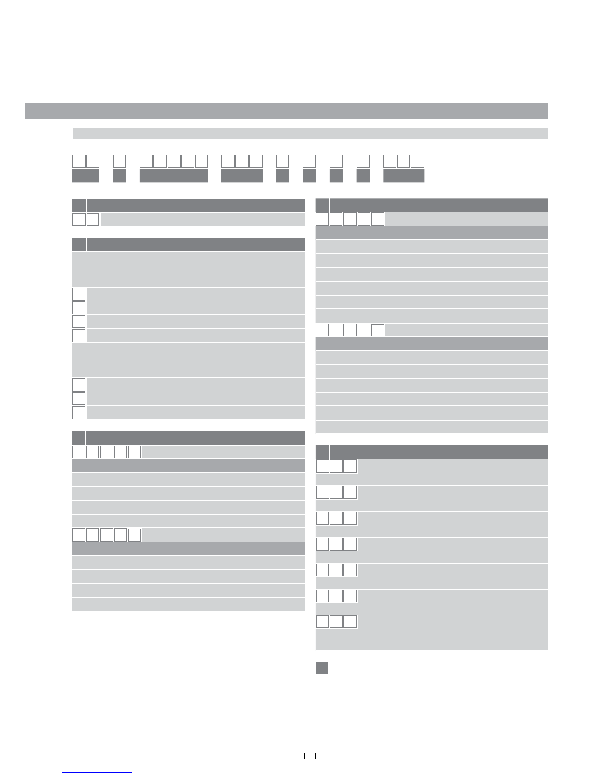
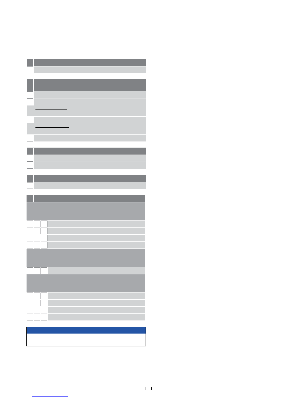
3. Identication
3.1 Order code of Temposonics® TH
T H 1 N
a b c d e f g h i
a Sensor model
T H
Rod
b Design
Enclosure Type 3:
TH rod sensor with housing material stainless steel 1.4305
(AISI 303) and rod material stainless steel 1.4306 (AISI 304L)
M
Threaded ange with at-face (M18×1.5-6g)
N
Threaded ange with raised-face (M18×1.5-6g)
S
Threaded ange with at-face (¾"-16 UNF-3A)
T
Threaded ange with raised-face (¾"-16 UNF-3A)
Enclosure Type 3X:
TH rod sensor with housing material stainless steel 1.4404
(AISI 316L) and rod material stainless steel 1.4404 (AISI 316L)
F
Threaded ange with at-face (¾"-16 UNF-3A)
G
Threaded ange with raised-face (¾"-16 UNF-3A)
W
Threaded ange with at-face (M18×1.5-6g)
d Connection type
C 0 1
Side connection with thread ½"-14 NPT
(All versions)
C 1 0
Top connection with thread ½"-14 NPT
(All versions)
M
0 1
Side connection with thread M16×1.5-6H
(Version E & N)
M
1 0
Top connection with thread M16×1.5-6H
(Version E & N)
N
0 1
Side connection with thread M20×1.5-6H
(All versions)
N
1 0
Top connection with thread M20×1.5-6H
(All versions)
N
F 1
Side connection with thread M20×1.5-6H
(Version E & N)
Note: Not available for SIL 2 version!
See next page
e
*/ Non standard stroke lengths are available; must be encoded in 5 mm / 0.1 in. increments
c Stroke length
X X X X M
0025…1500 mm (SIL 2)
X X X X
U
001.0…060.0 in. (SIL 2)
.
Standard stroke length (mm)* Ordering steps
25 … 500 mm 5 mm
500 … 750 mm 10 mm
750…1000 mm 25 mm
1000…1500 mm 50 mm
Standard stroke length (in.)* Ordering steps
1 …20 in. 0.2 in.
20 …30 in. 0.4 in.
30 …40 in. 1.0 in.
40 …60 in. 2.0 in.
1 2 3 4 5 6 7 8 9 10 11 12 13 14 15 16 17 18
c Stroke length (continued)
X X X X M
0025…7620 mm (standard)
X X X X
U
001.0…300.0 in. (standard)
.
Standard stroke length (mm)* Ordering steps
25 … 500 mm 5 mm
500 … 750 mm 10 mm
750…1000 mm 25 mm
1000…2500 mm 50 mm
2500…5000 mm 100 mm
5000…7620 mm 250 mm
Standard stroke length (in.)* Ordering steps
1 … 20 in. 0.2 in.
20 … 30 in. 0.4 in.
30 … 40 in. 1.0 in.
40…100 in. 2.0 in.
100…200 in. 4.0 in.
200…300 in. 10.0 in.
8
Temposonics® TH Analog ATEX / IECEx / CEC / NEC / KCs / EAC Ex certied / Japanese approval / Safety SIL 2 capable
Operation Manual
NOTICE
Use magnets of the same type (e.g. 2 ring magnets with part no.
201 542-2 ) for multi-position measurement.
e Operating voltage
1
+24 VDC (−15 / +20 %)
f
Version
(see chapter 8 and chapter 9 for further information)
D
Ex db and Ex tb (A/F 55)
E
Ex db eb and Ex tb (A/F 55)
US & CA approval: Ex nA /NI (for Zone 2 and 22)
(Note: US & CA approval is only available for SIL 2 version)
G
Ex db and Ex tb (A/F 60)
US & CA approvals: Explosionproof (XP)
(Note: Group A is not available for Canada)
N
Not approved
g Functional safety type
N
Not approved
S
SIL 2 (with certicate and manual)
h Additional option type
N
None
i Output
1 output with 1 position magnet
Output 1 (position magnet 1)
(Available outputs for SIL 2: A01 and A11)
A
0 1
4…20 mA
A
1 1
20…4 mA
A 2
1
0…20 mA
A 3
1
20…0 mA
2 outputs with 1 position magnet
Output 1 (position magnet 1) + output 2 (position magnet 1)
Notice: Not available for SIL 2 version!
A
0
3
4…20 mA 20…4 mA
2 outputs with 2 position magnets
Output 1 (position magnet 1) + output 2 (position magnet 2)
Notice: Not available for SIL 2 version!
A
0
2
4…20 mA 4…20 mA
A
1
2
20…4 mA 20…4 mA
A 2 2
0…20 mA 0…20 mA
A 3 2
20…0 mA 20…0 mA
9
Temposonics® TH Analog ATEX / IECEx / CEC / NEC / KCs / EAC Ex certied / Japanese approval / Safety SIL 2 capable
Operation Manual
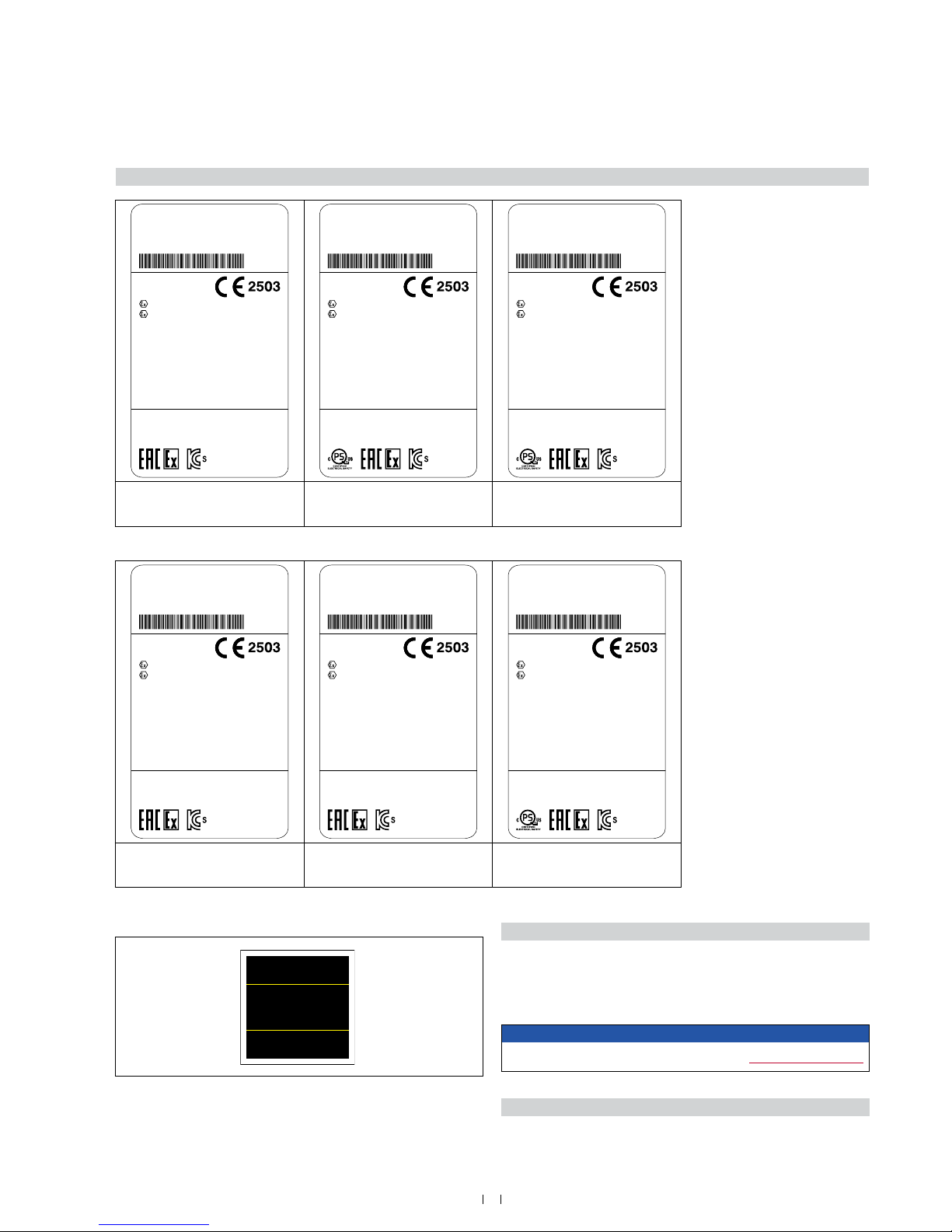
3.2 Nameplate (example)
3.3 Approvals
See chapter “8. Technical data Temposonics
®
TH SIL 2” on page
36ff and chapter “9. Technical data Temposonics
®
TH standard” on
page 39 ff..
3.4 Scope of delivery
TH (rod sensor):
• Sensor
Fig. 1: Example of a nameplate of a TH sensor (SIL 2 version)
Fig. 2: Example of a nameplate of a TH sensor (standard version)
Fig. 3: Label for japanese approval
NOTICE
For a detailed overview of the certications, see www.mtssensors.com
CML 17JPN1072X
MTS Sensors
労(平29年 7月)検
THN0080MC011DSNA11
In: 24 VDC 100 mA YofC: 26/2018
Out: 20-4 mA
Enclosure type 3 S/N: 18260255
CML ATEX1090X
IECEx CML 16.0039X
II 1/2G Ex db IIC T4 Ga/Gb
II 1G/2D Ex tb IIIC T130 °C Ga/Db
18-KA4BO-0247X 18-KA4BO-0248X
−40 °C ≤ Ta ≤ 85 °C IP66 / IP67
Датчик серии Т ОС ВО ЗАО ТИБР
№TC RU С-DE.ГБ08.B.01976
Ga/Gb Ex db IIC T4 X
Da/Db Ex tb IIIC T130 °C X
THN0080MC011ESNA11
In: 24 VDC 100 mA YofC: 26/2018
Out: 20-4 mA
Enclosure type 3 S/N: 18260255
CML ATEX1090X
IECEx CML 16.0039X
II 1/2G Ex db eb IIC T4 Ga/Gb
II 1G/2D Ex tb IIIC T130 °C Ga/Db
18-KA4BO-0249X 18-KA4BO-0250X
Class I, Div. 2, Groups A, B, C, D T4
Class II/III, Div. 2, Groups E, F, G T130 °C
Ex nA / AEx nA IIC T4 Gc
Ex tc / AEx tc IIIC T130 °C Dc
−40 °C ≤ Ta ≤ 80 °C IP66 / IP67
Датчик серии Т ОС ВО ЗАО ТИБР
№TC RU С-DE.ГБ08.B.01976
Ga/Gb Ex db eb IIC T4 X
Da/Db Ex tb IIIC T130 °C X
THN0080MC011GSNA11
In: 24 VDC 100 mA YofC: 26/2018
Out: 20-4 mA
Enclosure type 3 S/N: 18260255
CML ATEX1090X
IECEx CML 16.0039X
II 1/2G Ex db IIC T4 Ga/Gb
II 1G/2D Ex tb IIIC T 130 °C Ga/Db
18-KA4BO-0247X 18-KA4BO-0248X
Class I, Div. 1, Groups A, B, C, D T4
Class II/III, Div. 1, Groups E, F, G T130 °C
Class I, Zone 0/1 AEx d / Ex d IIC T4
Class II/III, Zone 21 AEx tb / Ex tb IIIC T130 °C
Group A is not approved for Canada
−40 °C ≤ Ta ≤ 85 °C IP66 / IP67
Датчик серии Т ОС ВО ЗАО ТИБР
№TC RU С-DE.ГБ08.B.01976
Ga/Gb Ex db IIC T4 X
Da/Db Ex tb IIIC T130 °C X
Variant with flameproof
connection chamber
Version D
Variant with increased safety
connection chamber
Version E
Variant with flameproof / explosionproof
connection chamber
Version G
THN0080MC011DNNA11
In: 24 VDC 100 mA YofC: 26/2018
Out: 20-4 mA
Enclosure type 3 S/N: 18260255
CML ATEX1090X
IECEx CML 16.0039X
II 1/2G Ex db IIC T4 Ga/Gb
II 1G/2D Ex tb IIIC T130 °C Ga/Db
18-KA4BO-0247X 18-KA4BO-0248X
−40 °C ≤ Ta ≤ 75 °C IP66 / IP67
Датчик серии Т ОС ВО ЗАО ТИБР
№TC RU С-DE.ГБ08.B.01976
Ga/Gb Ex db IIC T4 X
Da/Db Ex tb IIIC T130 °C X
THN0080MC011ENNA11
In: 24 VDC 100 mA YofC: 26/2018
Out: 20-4 mA
Enclosure type 3 S/N: 18260255
CML ATEX1090X
IECEx CML 16.0039X
II 1/2G Ex db eb IIC T4 Ga/Gb
II 1G/2D Ex tb IIIC T130 °C Ga/Db
18-KA4BO-0249X 18-KA4BO-0250X
Датчик серии Т ОС ВО ЗАО ТИБР
№TC RU С-DE.ГБ08.B.01976
Ga/Gb Ex db eb IIC T4 X
Da/Db Ex tb IIIC T130 °C X
−40 °C ≤ Ta ≤ 75 °C IP66 / IP67
THN0080MC011GNNA11
In: 24 VDC 100 mA YofC: 26/2018
Out: 20-4 mA
Enclosure type 3 S/N: 18260255
CML ATEX1090X
IECEx CML 16.0039X
II 1/2G Ex db IIC T4 Ga/Gb
II 1G/2D Ex tb IIIC T 130 °C Ga/Db
18-KA4BO-0247X 18-KA4BO-0248X
Class I, Div. 1, Groups A, B, C, D T4
Class II/III, Div. 1, Groups E, F, G T130 °C
Class I, Zone 0/1 AEx d / Ex d IIC T4
Class II/III, Zone 21 AEx tb / Ex tb IIIC T130 °C
Group A is not approved for Canada
−40 °C ≤ Ta ≤ 75 °C IP66 / IP67
Датчик серии Т ОС ВО ЗАО ТИБР
№TC RU С-DE.ГБ08.B.01976
Ga/Gb Ex db IIC T4 X
Da/Db Ex tb IIIC T130 °C X
Variant with flameproof
connection chamber
Version D
Variant with increased safety
connection chamber
Version E
Variant with flameproof / explosionproof
connection chamber
Version G
10
Temposonics® TH Analog ATEX / IECEx / CEC / NEC / KCs / EAC Ex certied / Japanese approval / Safety SIL 2 capable
Operation Manual
4.1 Functionality and system design
Product designation
• Position sensor Temposonics® T-Series
Sensor model
• Temposonics® TH (rod sensor)
Stroke length
• Stroke length SIL 2 version: 25…1500 mm (1…60 in.)
• Stroke length standard version: 25
…7620 mm (1…300 in.)
Output signal
• Analog
Application
Temposonics® position sensors are used for measurement and conversion of the length (position) variable in the elds of automated systems
and mechanical engineering.
The T-Series sensors are designed for installation in a raised or atface anged hydraulic cylinder, for use as an open-air position sensor
or as a liquid level sensor with the addition of a oat.
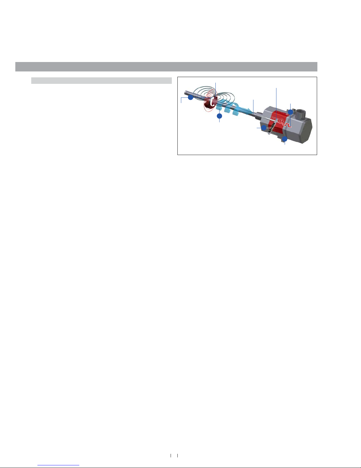
Principle of operation and system construction
The absolute, linear position sensors provided by MTS Sensors
rely on the company’s proprietary Temposonics
®
magnetostrictive
technology, which can determine position with a high level of
precision and robustness. Each Temposonics
®
position sensor
consists of a ferromagnetic waveguide, a position magnet, a strain
pulse converter and supporting electronics. The magnet, connected
to the object in motion in the application, generates a magnetic eld
at its location on the waveguide. A short current pulse is applied to
the waveguide. This creates a momentary radial magnetic eld and
torsional strain on the waveguide. The momentary interaction of the
magnetic elds releases a torsional strain pulse that propagates the
length of the waveguide. When the ultrasonic wave reaches the end of
the waveguide it is converted into an electrical signal. Since the speed
of the ultrasonic wave in the waveguide is precisely known, the time
required to receive the return signal can be converted into a linear
position measurement with both high accuracy and repeatability.
Fig. 4: Time-of-ight based magnetostrictive position sensing principle
4. Product description and commissioning
T-Series models
The T-Series is available in four variations, three of which are hazardous
classications:
• Flameproof housing with ameproof connection chamber (version D)
• Flameproof (explosionproof) housing with ameproof (explosion-
proof) connection chamber (version G)
• Flameproof housing with increased safety connection chamber
(version E)
• Non-hazardous (version N)
All of these variations are available in two types of hardware / software,
SIL 2 compliant and standard, both in 4…20 mA and 20…4 mA output. The sensor assembly is offered in 1.4305 (AISI 303) stainless steel
and in 1.4404 (AISI 316L). Associated with hazardous rating the sensor
meets IP66 / IP67. For non-hazardous environments the sensor meets
IP66, IP67, IP68, IP69K and NEMA 4X.
5
Sensing element
(Waveguide)
Position magnet (Magnetic fi eld)
Torsional strain
pulse converter
4
Current pulse
generates
magnetic fi eld
Interaction with
position magnet
fi eld generates
torsional strain
pulse
Torsional strain
pulse propagates
Strain pulse
detected by
converter
Time-of-fl ight converted
into position
1
2
3
11
Temposonics® TH Analog ATEX / IECEx / CEC / NEC / KCs / EAC Ex certied / Japanese approval / Safety SIL 2 capable
Operation Manual
Fig. 5: Temposonics® TH with ring magnet
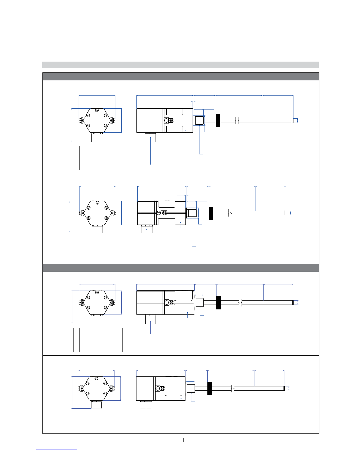
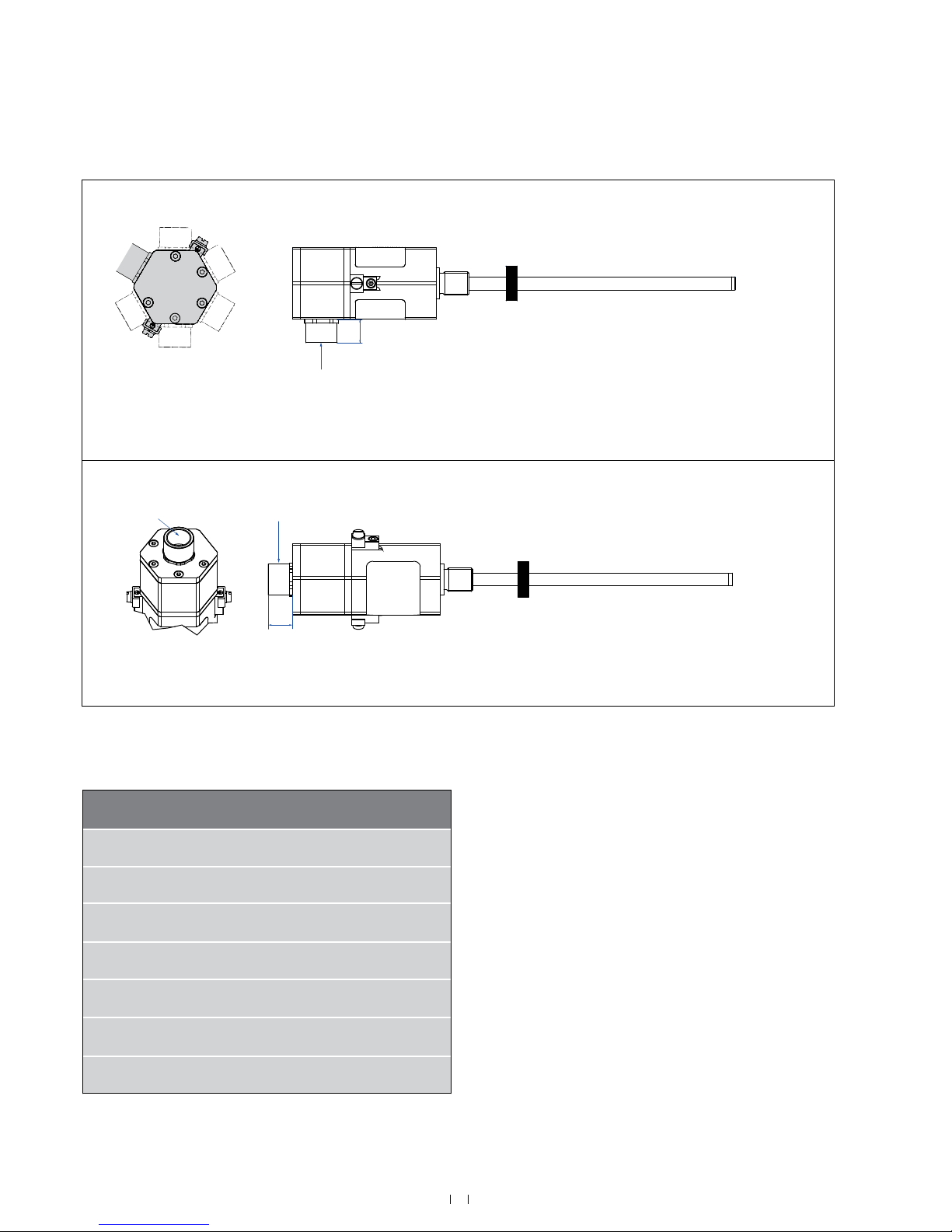
4.2 Styles and installation of Temposonics® TH
Threaded ange with raised-face
Version D & G
2.5
(0.1)
(2.01)
Null zone
51
Sensor electronics housing
132.5
(5.22)
Magnet
Ø 10 ± 0.13
(Ø 0.39 ± 0.01)
Refer to “Table 1” for
“TH rod sensor threaded flange type references”
A
B
C
Version D
77 (3.03)
83.8 (3.29)
55 (2.17)
Version G
82 (3.23)
89.2 (3.51)
60 (2.36)
A
B
C
Version D: A/F 55
Version G: A/F 60
See order code section “d” for connection types
M18×1.5-6g:
Ø 23.8 ± 0.2 (Ø 0.94 ± 0.01)
¾"-16 UNF-3A:
Ø 25.4 ± 0.2 (Ø 1 ± 0.01)
22.5
(0.89)
Stroke length
Standard: 25…7620 (1…300)
SIL 2: 25…1500 (1…60)
Dead zone
63.5 (2.5) /
66* (2.6)*
* Stroke length > 5000 mm (196.9 in.)
on page 12
Version E & N
2.5
(0.1)
83.8
(3.29)
73
(2.87)
55
(2.17)
Null zone
51
(2.01)
Sensor electronics housing
112.5
(4.43)
Magnet
Ø 10 ± 0.13
(Ø 0.39 ± 0.01)
Refer to “Table 1” for
“TH rod sensor threaded flange type references”
A/F 55
See order code section “d” for connection types
M18×1.5-6g:
Ø 23.8 ± 0.2 (Ø 0.94 ± 0.01)
¾"-16 UNF-3A:
Ø 25.4 ± 0.2 (Ø 1 ± 0.01)
22.5
(0.89)
Stroke length
Standard: 25…7620 (1…300)
SIL 2: 25…1500 (1…60)
Dead zone
63.5 (2.5) /
66* (2.6)*
* Stroke length > 5000 mm (196.9 in.)
Threaded ange with at-face
Version D & G
Null zone
51
(2.01)
Sensor electronics housing
132.5
(5.22)
83.8
(3.29)
55
(2.17)
73
(2.87)
Sensor electronics housing
112.5
(4.43)
Null zone
51
(2.01)
Refer to “Table 1” for
“TH rod sensor threaded flange type references”
Refer to “Table 1” for
“TH rod sensor threaded flange type references”
Ø 10 ± 0.13
(Ø 0.39 ± 0.01)
Ø 10 ± 0.13
(Ø 0.39 ± 0.01)
A
B
C
Version D
77 (3.03)
83.8 (3.29)
55 (2.17)
Version G
82 (3.23)
89.2 (3.51)
60 (2.36)
A
B
C
Version D: A/F 55
Version G: A/F 60
A/F 55
Magnet
Magnet
See order code section “d” for connection types
See order code section “d” for connection types
22.5
(0.89)
22.5
(0.89)
Stroke length
Standard: 25…7620 (1…300)
SIL 2: 25…1500 (1…60)
Stroke length
Standard: 25…7620 (1…300)
SIL 2: 25…1500 (1…60)
Dead zone
63.5 (2.5) /
66* (2.6)*
Dead zone
63.5 (2.5) /
66* (2.6)*
* Stroke length > 5000 mm (196.9 in.)
* Stroke length > 5000 mm (196.9 in.)
on page 12
Version E & N
83.8
(3.29)
55
(2.17)
73
(2.87)
Sensor electronics housing
112.5
(4.43)
Null zone
51
(2.01)
Refer to “Table 1” for
“TH rod sensor threaded flange type references”
Ø 10 ± 0.13
(Ø 0.39 ± 0.01)
A/F 55
Magnet
See order code section “d” for connection types
22.5
(0.89)
Stroke length
Standard: 25…7620 (1…300)
SIL 2: 25…1500 (1…60)
Dead zone
63.5 (2.5) /
66* (2.6)*
* Stroke length > 5000 mm (196.9 in.)
on page 12
on page 12
Controlling design dimensions are in millimeters and measurements in ( ) are in inches
12
Temposonics® TH Analog ATEX / IECEx / CEC / NEC / KCs / EAC Ex certied / Japanese approval / Safety SIL 2 capable
Operation Manual
Table 1: TH rod sensor threaded ange type references
Fig. 6: Temposonics
®
TH connection options
Threaded
ange type
Description
Threaded ange
F
Threaded ange with at-face
Stainless steel 1.4404 (AISI 316L)
¾"-16 UNF-3A
G
Threaded ange with raised-face
Stainless steel 1.4404 (AISI 316L)
¾"-16 UNF-3A
M
Threaded ange with at-face
Stainless steel 1.4305 (AISI 303)
M18×1.5-6g
N
Threaded ange with raised-face
Stainless steel 1.4305 (AISI 303)
M18×1.5-6g
S
Threaded ange with at-face
Stainless steel 1.4305 (AISI 303)
¾"-16 UNF-3A
T
Threaded ange with raised-face
Stainless steel 1.4305 (AISI 303)
¾"-16 UNF-3A
W
Threaded ange with at-face
Stainless steel 1.4404 (AISI 316L)
M18×1.5-6g
Side connection C01 / N01 / NF1 (with adapter) / M01 (without adapter)
Magnet
Connection length
22 mm (0.87 in.) for version D & G
18 mm (0.7 in.) for version E & N
Side connection
C01 / N01:
Connector on 6 different
positions at 60° each
NF1:
Connector on 4 different
positions at 60° each
Top connection C10 / N10 (with adapter) / M10 (without adapter)
Top connection
Top connection
Magnet
Connection length
22 mm (0.87 in.) for version D & G
18 mm (0.7 in.) for version E & N
13
Temposonics® TH Analog ATEX / IECEx / CEC / NEC / KCs / EAC Ex certied / Japanese approval / Safety SIL 2 capable
Operation Manual
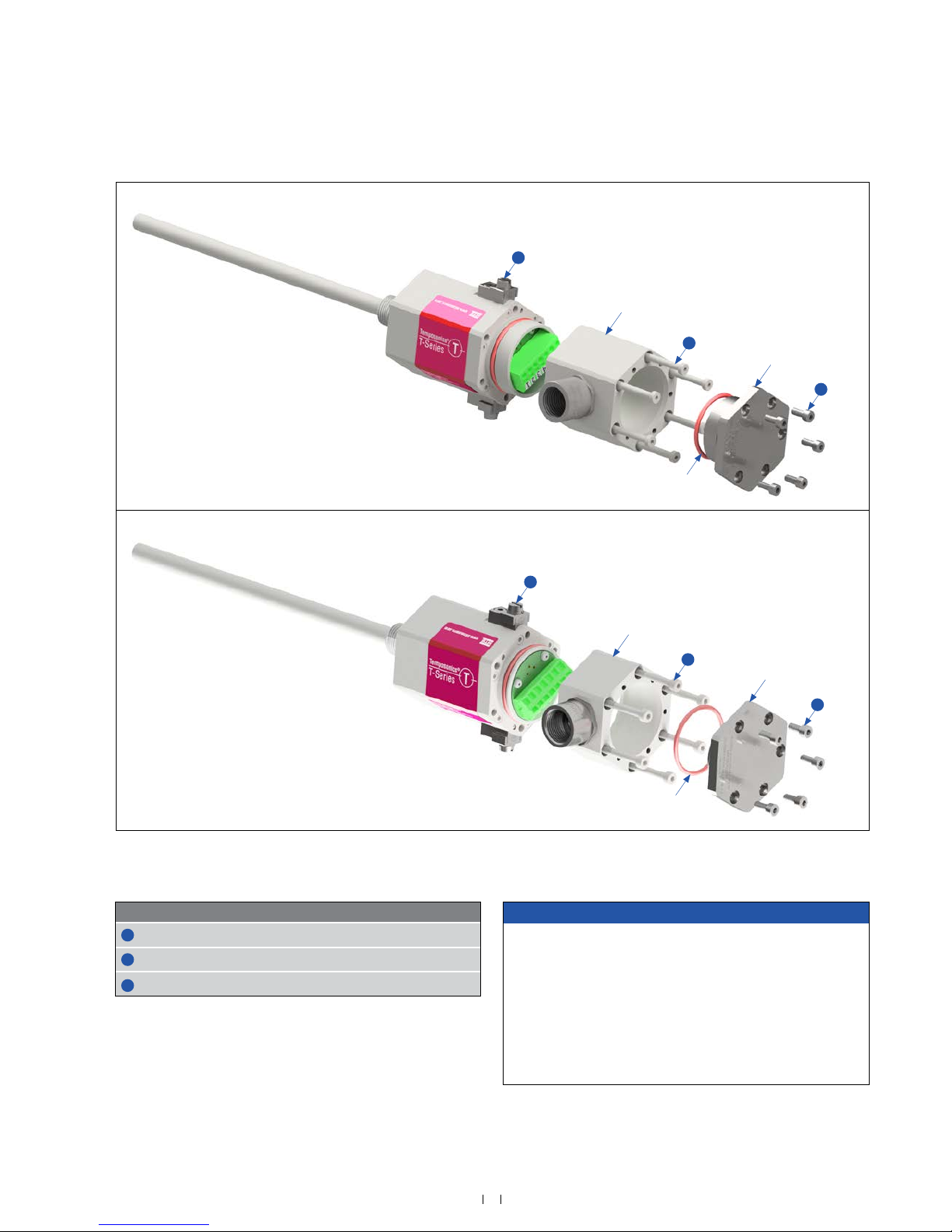
Fig. 7: Temposonics® TH exploded view drawing
NOTICE
Connect cable to sensor
See page 22 ff. for more details.
Change orientation of cable bushing (C01, M01, N01, NF1)
Loosen the ve hexagonal screws M4 (A/F 3) and remove the upper
lid (Fig. 7). Then loosen the six hexagonal screws M4 (A/F 3) of the
connection adapter (Fig. 7). Change the orientation of the connector
on six different positions at 60° each. Note the example on page
22 ff..
Part Fastening torque
1
Screw M4×10
1.2 Nm
2
Screw M4×40
1.2 Nm
3
Earthing connection: M5×8 for mounting
2.5 Nm
Version D & G
3
Connection adapter
2
1
O-ring
Upper lid
Version E & N
3
Connection adapter
2
1
Upper lid
O-ring
14
Temposonics® TH Analog ATEX / IECEx / CEC / NEC / KCs / EAC Ex certied / Japanese approval / Safety SIL 2 capable
Operation Manual
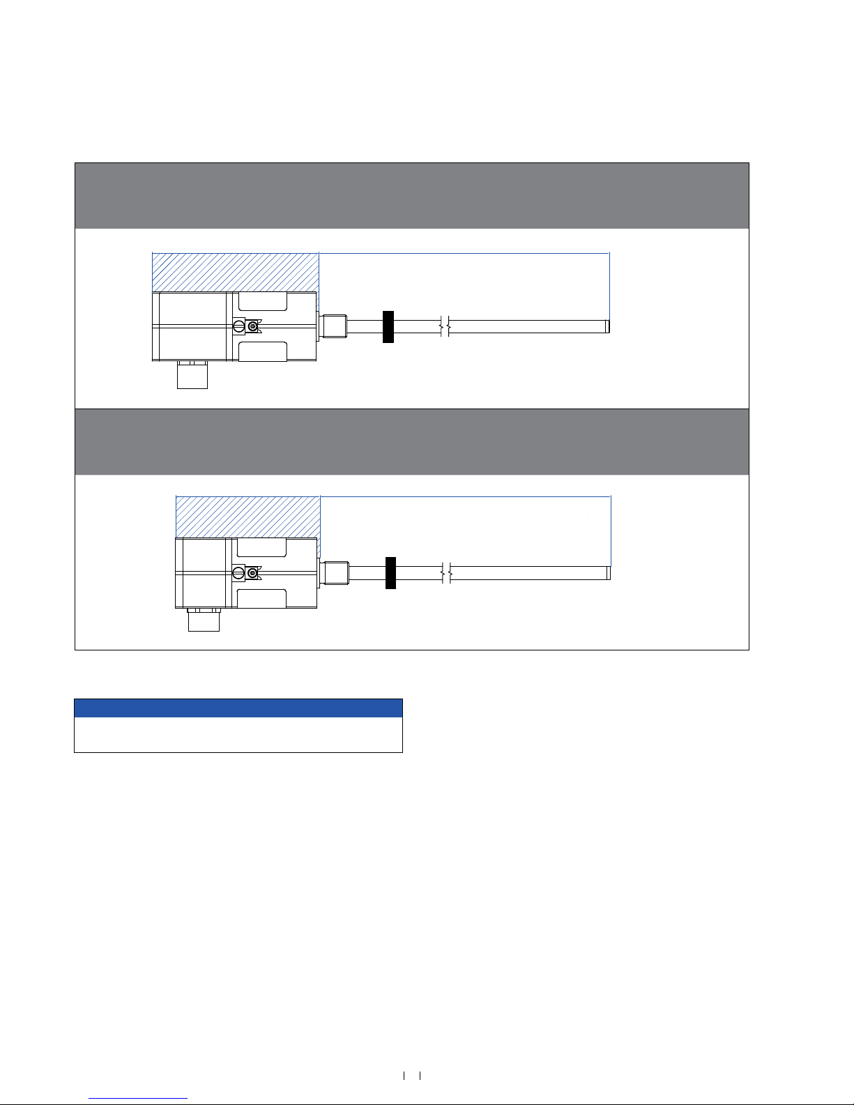
Fig. 8: Temposonics® TH Zone classication
NOTICE
Seal sensor according to ingress protection IP67 between Zone 0
and Zone 1.
Version D & G (example: Threaded fl ange with raised-face)
Flameproof (explosionproof) housing with fl ameproof (explosionproof) connection chamber
Version D: ATEX / IECEx / EAC Ex / Japanese Approval
Version G: ATEX / IECEx / CEC / NEC / EAC Ex / Japanese Approval
Zone 1 Zone 0
Magnet
Version E (example: Threaded fl ange with raised-face)
Flameproof housing with increased safety connection chamber
SIL 2: ATEX / IECEx / CEC / NEC / EAC Ex / Japanese Approval
Standard: ATEX / IECEx / EAC Ex / Japanese Approval
Zone 1 Zone 0
Magnet
 Loading...