

MTS Sensors Temposonics RP, Temposonics RH Datasheet
Temposonics
®
Magnetostrictive, Absolute, Non-contact
Linear-Position Sensors
®
SENSORS
R-Series Models RP and RH
Analog Outputs (Voltage/Current)
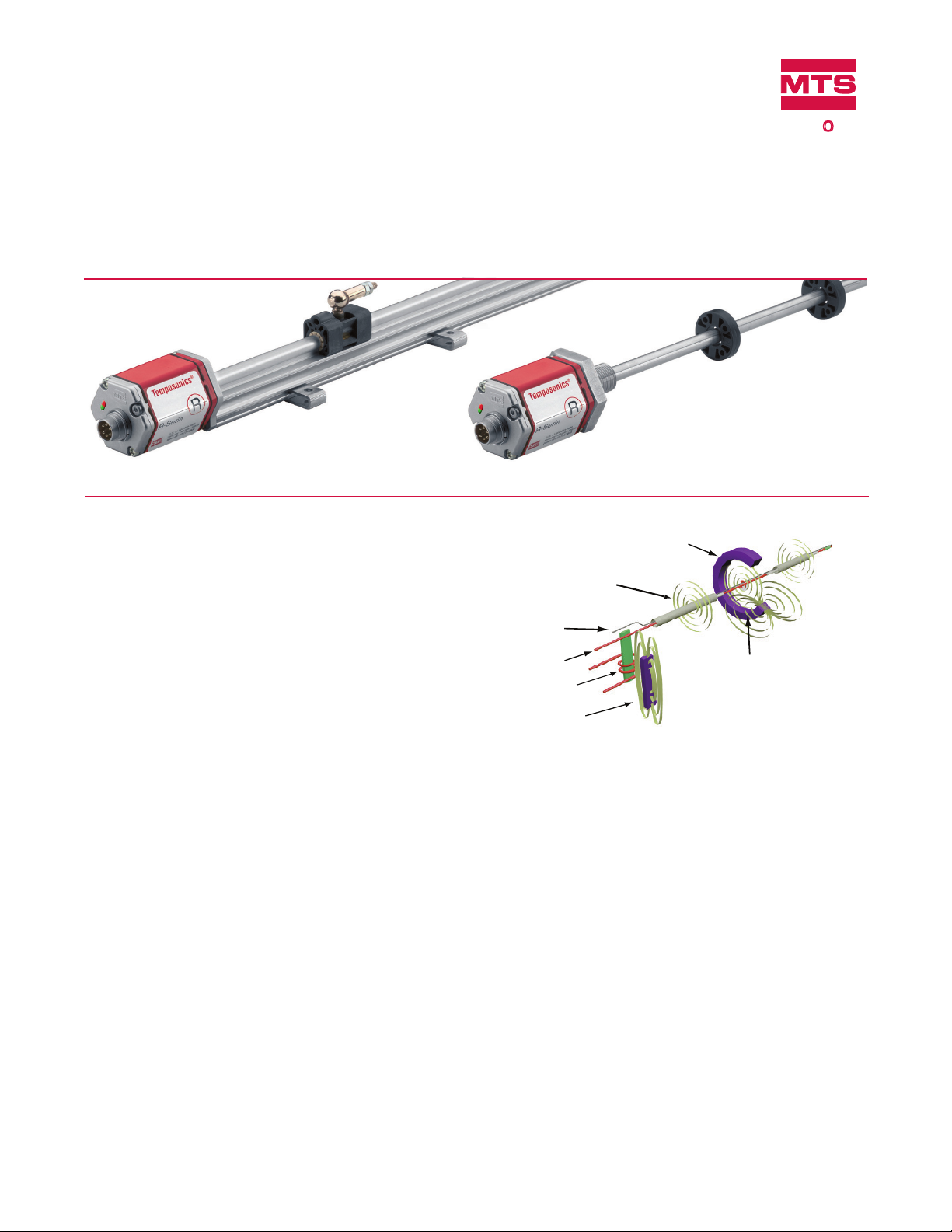
Model RP Prole-style position sensor
FEATURES
Linear, Absolute Measurement
LEDs For Sensor Diagnostics
Non-Contact Sensing Technology
Linearity Deviation Less Than 0.01%
Repeatability Within 0.001%
Direct Analog Outputs (Voltage or Current)
Single or Dual Channel Outputs (Position + Speed)
BENEFITS
Rugged Industrial Sensor
Dual Magnet Position Measurement
100% Field Adjustable Null And Span Setpoints
Data Sheet
Document Part Number
550992 Revision E
Model RH Rod-style position sensor
Time-based Magnetostrictive position sensing principle
Movable position magnet
Magnetic field encompasses
entire waveguide - generated
by the interrogation pulse
Interrogation
Return wire
Waveguide
Strain-Pulse detector
Bias magnet
Magnetic field from
position magnet
Interaction of magnetic
fields causes waveguide to
generate a strain pulse
APPLICATIONS
Continuous Operation In Harsh Industrial Conditions
High Pressure Conditions
For Accurate, Dual-Magnet Position Measurement
TYPICAL INDUSTRIES
Fluid Power
Factory Automation
Material Handling and Packaging
Woodworking, Metalworking and Assembly Tools
Plastic Injection and Blow Molding
Benefits of Magnetostriction
Temposonics linear-position sensors use the time-based magnetostrictive position sensing principle developed by MTS. Within the
sensing element, a sonic-strain pulse is induced in a specially designed
magnetostrictive waveguide by the momentary interaction of two
magnetic fields. One field comes from a moveable permanent magnet
that passes along the outside of the sensor. The other field comes
from an “interrogation” current pulse applied along the waveguide.
The resulting strain pulse travels at sonic speed along the waveguide
and is detected at the head of the sensing element.
The position of the magnet is determined with high precision and
speed by accurately measuring the elapsed time between the application of the interrogation pulse and the arrival of the resulting strain
pulse with a high-speed counter. The elapsed time measurement is
directly proportional to the position of the permanent magnet and is
an absolute value. Therefore, the sensor's output signal corresponds
to absolute position, instead of incremental, and never requires
recalibration or re-homing after a power loss. Absolute, non-contact
sensing eliminates wear, and guarantees the best durability and output
repeatability.
All specifications are subject to change. Contact MTS for specifications and
engineering drawings that are critical to your application. Drawings contained
in this document are for reference only. Go to http://www.mtssensors.com for
the latest support documentation and related media.

Product Overview and Specifications
Product overview
R-Series model RH and RP sensors are extremely robust and are ideal for continuous operation under harsh industrial conditions. MTS offers
two standard sensor housings, rod and profile extrusion. The rod housing is capable of withstanding high pressures such as those found
in hydraulic cylinders. The profile extrusion housing provides convenient mounting options and captive sliding magnets which utilize slide
bearings of special material that reduce friction, and help mitigate dirt build up. The sensor head contains the active signal conditioning and a
complete integrated electronics interface. Double shielding is used to ensure EMI protection for unsurpassed reliability and operating safety.
Product specifications
Parameters Specifications
OUTPUT
Measured output
variables:
Position + speed (magnitude) or velocity
(with direction) for single or dual magnets
Resolution: Position measurement:
16 bit; 0.0015% (minimum 1 µm)
Speed measurement:
0.1 mm/s
Linearity
deviation:
< ± 0.01% full stroke
(minimum ± 50 µm)
Repeatability: < ± 0.001% full stroke
(minimum ± 2.5 µm)
Hysteresis: < 4 µm
Analog Outputs: Voltage:
0 to 10, 10 to 0, -10 to +10, +10 to -10
Vdc (minimum controller load >5k ohms)
Current:
4(0) to 20 mA, 20 to 4(0) mA
(minimum/maximum load 0/500 ohms)
Stroke lengths: Range (Prole style):
25 to 5080 mm (1 to 200 in.)
Range (Rod style):
25 to 7620 mm (2 to 300 in.)
Update times:
0.5 ms up to 1200 mm, 1.0 ms up to
2400 mm, 2.0 ms up to 4800 mm, 5.0 ms up
to 7620 mm stroke length
Speed
measurement:
Range:
0.025 - 10 m/s (1.0 - 400.0 in./s)
Deviation: <0.5%
Resolution:
0.1 mm/s (0.004 in./s)
Update time:
Refer to update times in
'Position measurement' above
ELECTRONICS
Operating
voltage:
+24 Vdc nominal: -15% or +20% *
Polarity protection: up to -30 Vdc
Over voltage protection: up to 36 Vdc
Current drain: 100 mA typical
Dielectric withstand voltage: 500 Vdc
(DC ground to machine ground)
Setpoint adjustment (Null/Span):
100% of electrical stroke length. 25 mm
Setpoints:
(0.98 in.) min. distance between setpoints.
For dual-magnet outputs:
76 mm (3 in.) min. distance between
magnets
Parameters Specifications
ENVIRONMENTAL
Operating
conditions:
Operating temperature:
-40 °C (-40 °F) to +75 °C (+167 °F)
Relative humidity: 90% no condensation
Temperature coefficient: < 30 ppm/ °C
EMC test: Electromagnetic emission:
IEC/EN 50081-1
Electromagnetic susceptibility:
IEC/EN 50082-2, IEC/EN 61000-4-2/3/4/6,
level 3/4 criterium A, CE qualified
Shock rating: 100 g (single hit)/
IEC standard 68-2-27 (survivability)
Vibration rating: 15 g (30 g with HVR option)/10 to 2000 Hz,
IEC standard 68-2-6 (operational)
WIRING
Connection type: 6-pin male D60 (M16) connector or
integral cable
PROFILE STYLE SENSOR (MODEL RP)
Electronic head: Aluminum housing with diagnostic LED
display
(LEDs located beside connector/cable exit)
Sealing: IP 65**
Sensor extrusion: Aluminum (Temposonics profile style)
Mounting: Any orientation. Adjustable mounting feet
or T-slot nut (M5 threads) in bottom groove
Magnet types: Captive-sliding magnet or open-ring
magnet
ROD STYLE SENSOR (MODEL RH)
Electronic head: Aluminum housing with diagnostic LED
display
(LEDs located beside connector/cable exit)
Sealing: IP 67 or IP 68 for integral cable models**
Sensor rod: 304L stainless steel
Operating
pressure:
350 bar static, 690 bar peak
(5000 psi static, 10,000 psi peak)
Mounting: Any orientation. Threaded flange M18 x 1.5
or 3/4 - 16 UNF-3A
Typical
mounting torque:
45 N-m (33 ft. - lbs.)
Magnet types: Ring magnet, open-ring magnet, or magnet
float
* UL Recognition requires an approved power supply with energy limitation UL 61010-
1), or Class 2 rating according to the National Electrical Code (USA) / Canadian
Electrical Code.
R-Series Models RP and RH Temposonics® Linear-Position Sensors - Analog Outputs
Product Data Sheet, Document Part No.: 550992 Revision E (EN) 05/2014
** The IP rating is not part of the UL Recognition.
2
MTS Sensors
Output options
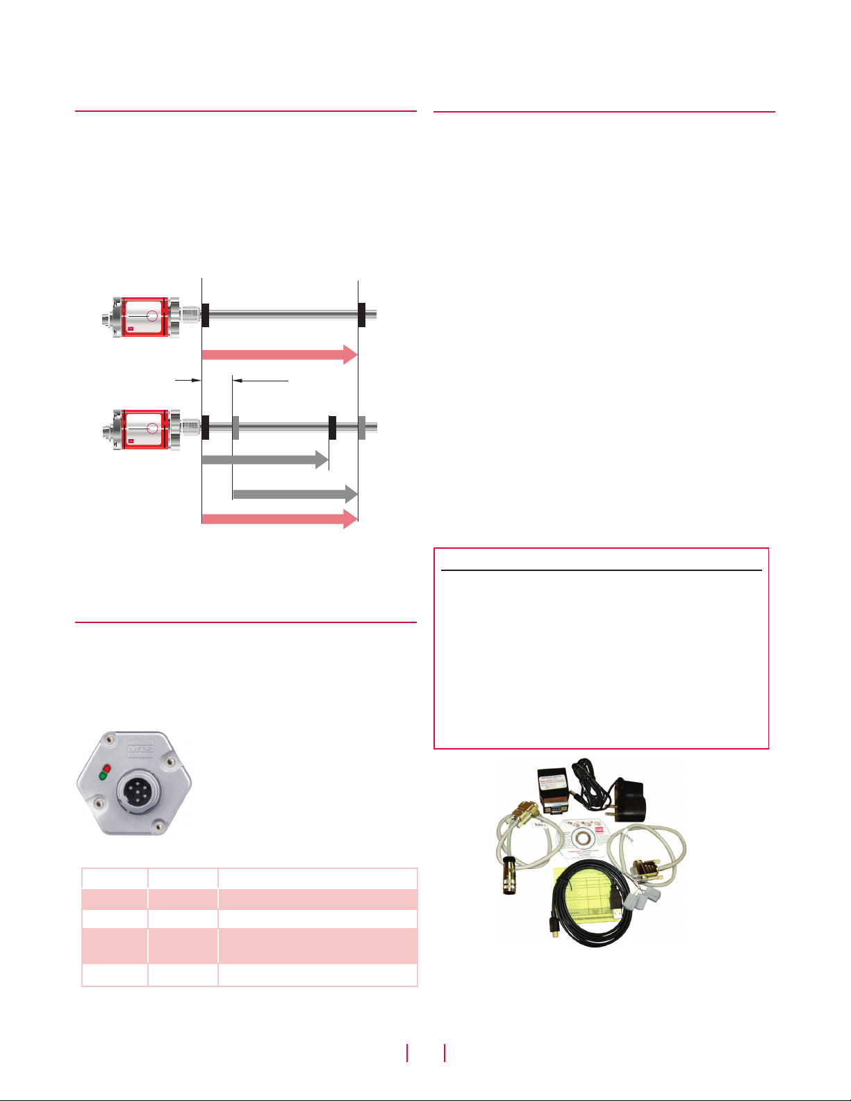
Single-magnet sensor
R-Series analog sensors provide single or dual-magnet sensor options
along with single or dual-channel outputs (see ‘Figure 1’).
The R-Series analog sensor can be ordered for single-position
magnet applications which provide one position output, and/or one
velocity output over the active stroke length.
The R-Series sensor can also be ordered for dual-position magnet applications which provide two position outputs, or two velocity outputs,
or one of each.
M1A
10 Vdc
M1A
M2A
®
Temposonics
R
R-Series
®
Dual-magnet sensor
®
Temposonics
R
R-Series
®
0 Vdc
M1
M1
Active stroke range
Position / Speed
75 mm
(3 in.) min.
M2
Analog Output Options, Programmability
Enhanced Monitoring and Diagnostics
Advanced communication and programmability
SENSOR FIELD PROGRAMMING
Temposonics R-Series Analog sensors are pre-configured at the
factory by model number designation. For many applications, normal
sensor installation and operation does not require additional adjustment. If however, sensor parameter changes are required in the field,
the ‘R-Series Analog PC Programming Kit, part no. 253309-1’ (see
‘Figure 3’) can be used to easily program the sensor electronically
without opening the sensor's housing.
Field programming to adjust the output values is available for any
setting needed, within the selected output range. Each sensor’s
output range is selected from the available options when ordering a
particular sensor model number. There are six different manufacturing build types available, three single channel and three dual channel
outputs in various ranges as described below:
Single-channel output for either position or speed:
• Voltage output between 0 and +10 volts
• Voltage output between -10 and +10 volts
• Current output between 0 (or 4) and 20 mA
Dual-channel outputs for position and/or speed:
Figure 1. Single and dual-magnet output diagram
When using dual magnets, the minimum allowed distance between the
magnets is 75 mm (3 in.) to maintain proper sensor output.
Enhanced monitoring and diagnostics
SENSOR STATUS AND DIAGNOSTIC DISPLAY
Diagnostic LEDs (green/red), located beside the connector or cable
exit (see ‘Figure 2’), provide basic visual monitoring for normal sensor operation and troubleshooting. Diagnostic display LEDs indicate
four modes described in ‘Table 1’.
Figure 2. R-Series sensor diagnostic LEDs
Green Red Operation status/mode
ON OFF Normal function (operation mode)
ON Flashing Magnet out of setup range
ON ON
Flashing ON Programming mode
Table 1. Diagnostic LED codes
0 Vdc
Position 1 / Position 2
0%
10 Vdc
100%
Magnet not detected or wrong
quantity of magnets
• Voltage outputs between 0 and +10 volts
• Voltage outputs between -10 and +10 volts
• Current outputs between 0 (or 4) and 20 mA
Field Programming Notes:
Field programming allows for numerous custom sensor configurations, however, please note that field programming can not be used to
change the R-Series Analog sensor from one manufacturing build type
to another.
Field programming (output voltages):
1. Sensor models ordered with one output channel can not be
reprogrammed in the field to provide a second output channel.
2. Sensor models ordered with positive only output voltages can not
be reprogrammed in the field to include negative output voltages.
3. Sensor models ordered with both positive and negative output
voltages can be reprogrammed in the field for positive only
voltages, or negative only voltages. However, resolution is then
reduced.
Figure 3. R-Series Analog PC Programming Kit, Part no. 253309-1
(For single or dual magnet sensor applications)
MTS Sensors
3
R-Series Models RP and RH Temposonics® Linear-Position Sensors - Analog Outputs
Product Data Sheet, Document Part No.: 550992 Revision E (EN) 05/2014
Field Programming
Advanced communication and programmability
SENSOR FIELD PROGRAMMING
R-Series Analog PC Programming Kit (Part no.: 253309-1)
includes the following components:
• Wall adapter style power supply (24 Vdc output)
• USB Serial converter box with USB cable to connect to PC
• Two connection cables:
– Cable with connector if sensor is ordered with the D60
integral connector option.
– Cable with quick connects if sensor is ordered with the
integral cable option.
• R-Series Analog PC Setup software, on CD-ROM
(for Windows XP or higher)
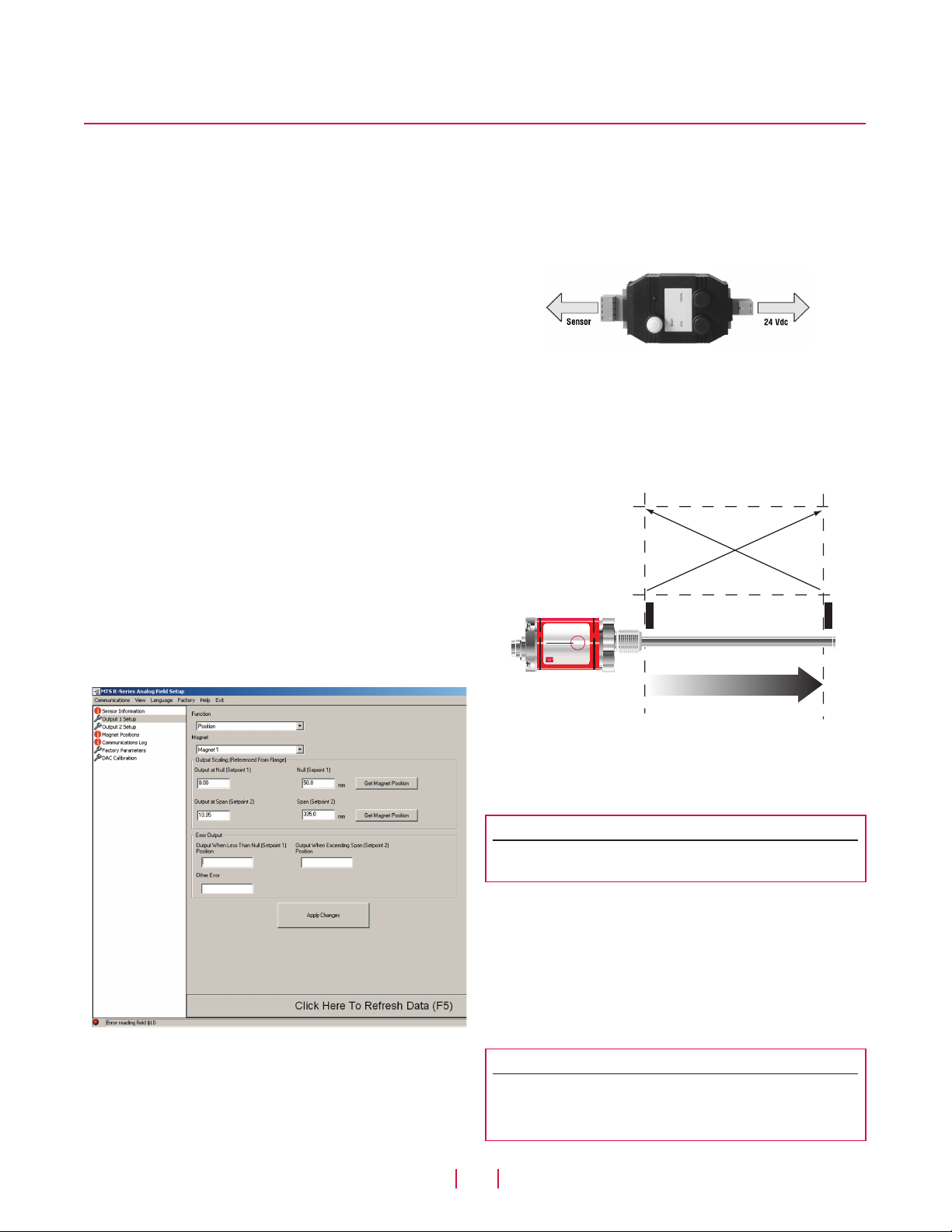
The R-Series Analog PC Setup software user-friendly interface
(see ‘Figure 4’) enables the operator to take advantage of customizing the following settings:
• Magnet positions and sensor output values for Setpoint 1 (Null)
and Setpoint 2 (Span) for single or dual magnets. For additional
information about setpoints, refer to section ‘R-Series analog
handheld programmer for single-magnet sensors’.
• Output range settings for speed, or for speed with direction.
• Assign position or velocity output functions for the single or
dual magnets, and for the one or two output channels. Output
function assignments are limited to the manufacturing build
type of the sensor.
• Assign error output values when the magnet moves beyond the
programmed setpoints.
R-SERIES ANALOG HANDHELD PROGRAMMER FOR SINGLE MAGNET SENSOR APPLICATIONS
The R-Series Analog Handheld Programmer (see Figure 5) can
be used to program the magnet positions for the start of output,
(0% = 0 Vdc, -10 Vdc, 4 mA, or 0 mA), and the end of output, (100%
= 10 Vdc or 20 mA), for the single magnet version of the R-Series
analog sensor.
Figure 5. R-Series Analog Handheld Programmer, Part no.: 253124
Standard factory settings place the setpoint 1 'Null' and setpoint 2
'Span' at the limits of the sensor’s active stroke range. For example,
a sensor ordered with 4 - 20 mA output will be factory set for 4 mA
output at the bottom limit of the stroke range at the 'Null position.
Likewise, the 20 mA output will be factory set at the top limit of the
stroke range at the 'Span' position.
Output value
Reverse
Forward
Electronics
housing
Temposonics
R-Series
®
®
R
Single-magnet sensor
Position
Dead
zone
Figure 4. R-Series PC Setup software interface
Setpoint 2
(Span)
Figure 6.
Setpoint 1
(Null)
Standard factory settings
Setpoint 1 and setpoint 2 can be re-positioned for the actual measuring length needed anywhere within the active stroke range.
Note:
The minimum distance allowed between setpoint 1 and setpoint 2 is
25 mm (0.98 in.).
These adjustments are easily performed, even when the sensor is not
directly accessible, by connecting the analog handheld programmer
to the sensor’s integral cable or extension cable.
When programming new setpoints, the R-Series Analog Handheld
Programmer adjusts the sensor output values to either 0% or 100%
at the two selected magnet positions. To program other setpoint
output values, use the ‘R-Series Analog PC Programming Kit’ (Part
no.: 253309-1)
.
Note:
The R-Series Analog Handheld Programmer can also be used to change
the output direction from forward-acting (e.g. 4 - 20 mA output) to
reverse-acting (20 - 4 mA output), as well as, reverse-acting to forwardacting.
R-Series Models RP and RH Temposonics® Linear-Position Sensors - Analog Outputs
Product Data Sheet, Document Part No.: 550992 Revision E (EN) 05/2014
4
MTS Sensors
Model RP Profile-Style Sensor Dimensions
R-SERIES ANALOG CABINET PROGRAMMER FOR SINGLE
MAGNET SENSORS
The R-Series Analog Cabinet Programmer (see Figure 7) provides the
same programming functions as the R-Series Analog Handheld Programmer and is designed to mount in a control cabinet. The R-Series
Analog Cabinet Programmer includes a rear snap-in mounting feature
that allows the unit to mount on standard 35 mm DIN rail.
After installation, the programmer can remain wired up to both the
sensor and PLC interface module if reprogramming or a different
machine setup is later required, a built-in ‘Program/Run’ switch
allows this programmability.
Figure 7. R-Series Analog Cabinet Programmer (two shown) ,
Part no.: 253408 (for single-magnet sensor applications)
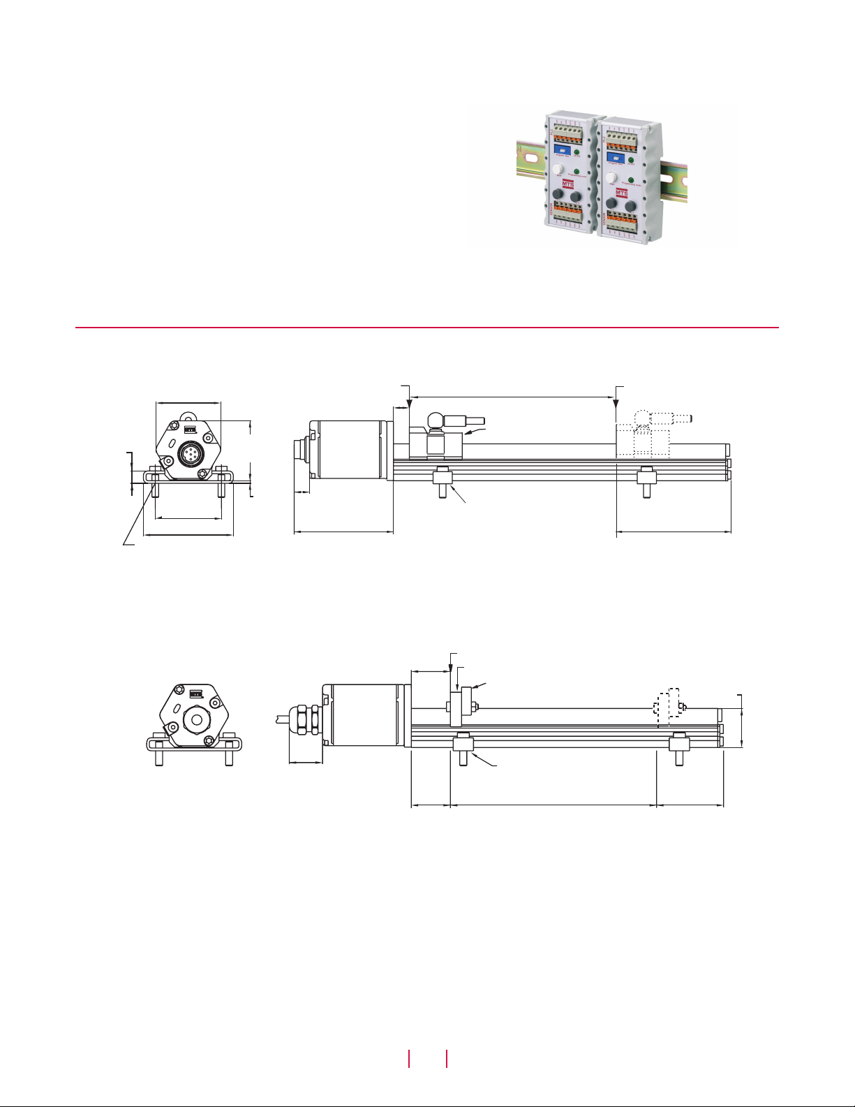
Model RP profile-style sensor dimension references
MODEL RP, PROFILE-STYLE SENSOR WITH CAPTIVE-SLIDING MAGNET
Drawing is for reference only, contact applications engineering for tolerance specific information.
Field Programming
9 mm
(0.36 in.)
49 mm
(1.92 in.)
50 mm (1.97 in.)
68 mm (2.68 in.)
5.5 mm (0.21 in.) dia.
for M5 or #10 screw
Beginning of stroke ‘Null’ position
12 mm (0.47 in.)
45 mm
(1.77 in.)
2 mm
(0.07 in.)
Electronics
housing
12 mm (0.47 in.)
75 mm
(2.95 in.)
Stroke length
Captive-sliding magnet
Mounting foot, moveable
(part no.: 400802)
End of stroke
‘Span’ position
82 mm (3.2 in.)
Dead zone
Figure 8. R-Series Model RP Profile-style sensor dimension reference (Shown with the D60 integral connection type option)
MODEL RP, PROFILE-STYLE SENSOR WITH OPEN-RING MAGNET
Drawing is for reference only, contact applications engineering for tolerance specific information.
Beginning of stroke ‘Null’ Position
28 mm
(1.1 in.)
Electronics
housing
30 mm
(1.2 in.)
28 mm
(1.1 in.)
Open-ring magnet
Mounting support
(non-ferrous material)
Mounting foot, moveable
(part no.: 400802)
Stroke length
Dead zone
66 mm
(2.6 in.)
28 mm
(1.1 in.)
Figure 9. R-Series Model RP Profile-style sensor dimension reference (Shown with the R05 integral cable connection type option)
MTS Sensors
R-Series Models RP and RH Temposonics® Linear-Position Sensors - Analog Outputs
Product Data Sheet, Document Part No.: 550992 Revision E (EN) 05/20145
 Loading...