

MTS Sensors Temposonics R, Temposonics RF Datasheet
Temposonics
®
Magnetostrictive, Absolute, Non-contact
Linear-Position Sensors
R-Series Model RF
Flexible Housing Option
Data Sheet
Model RF exible housing option for R-Series sensors with voltage, current, SSI, CANbus,
DeviceNet, Probus, EtherCAT® and EtherNet/IP outputs
FEATURES
Linear, Absolute Measurement Along an Arc
LEDs For Sensor Diagnostics
Non-Contact Sensing Technology
Linearity Deviation Less Than 0.02%
Repeatability Within 0.001%
Flexible Housing is Optional For MTS R-Series Sensors With
The Following Full Range of Outputs:
Voltage, Current, SSI, CANbus, DeviceNet, Profibus,
EtherCAT
Measuring Stroke Range:
255 mm (10 in.) to 10,060 mm (396 in.)
(Contact factory for longer stroke lengths)
®
and EtherNet/IP
Document Part Number
551081 Revision B
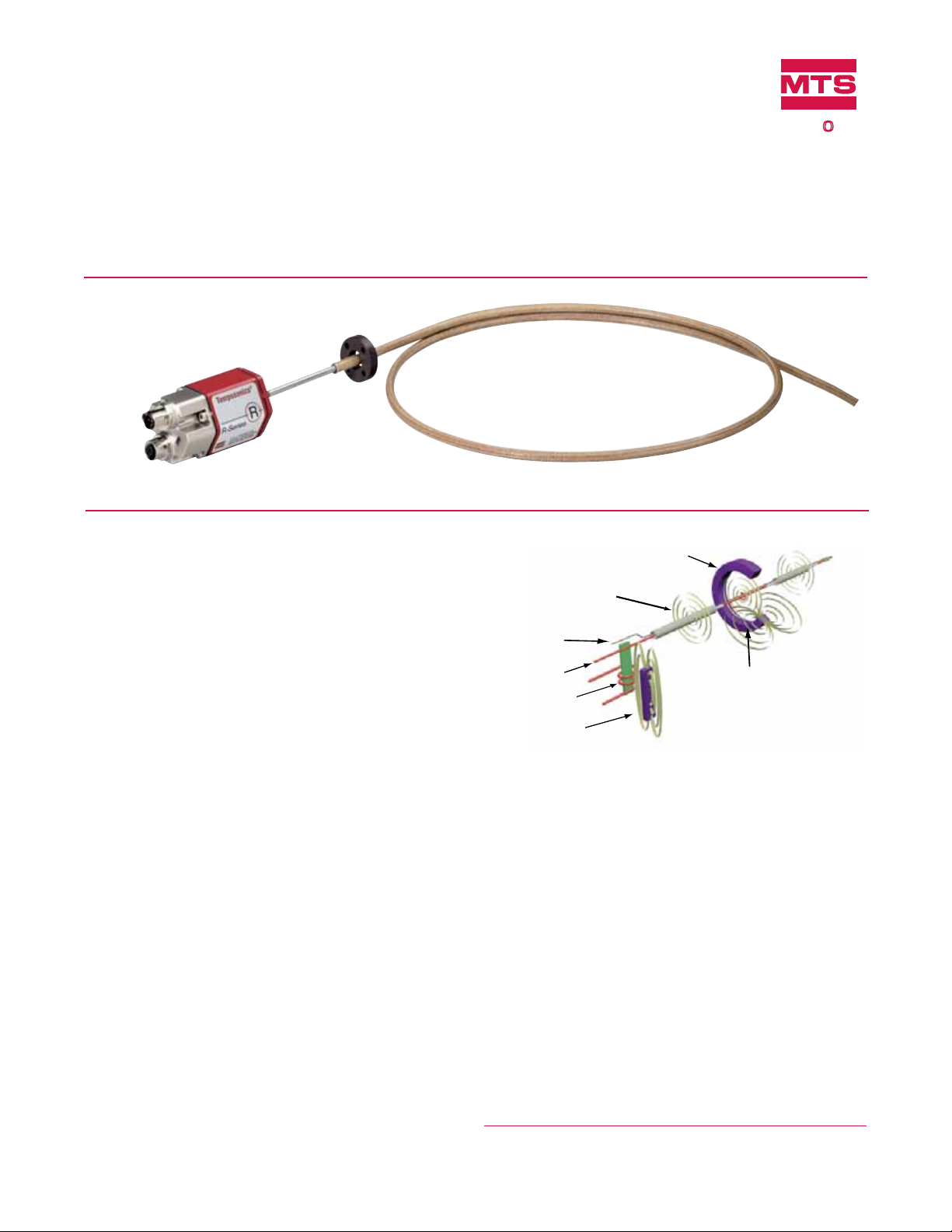
Time-based Magnetostrictive position sensing principle
Movable position magnet
Magnetic field encompasses
entire waveguide - generated
by the interrogation pulse
Interrogation
Return wire
Waveguide
Strain-Pulse detector
Bias magnet
SENSORS
Magnetic field from
position magnet
Interaction of magnetic
fields causes waveguide to
generate a strain pulse
®
BENEFITS
Rugged Industrial Sensor
Multi-Magnet Position Measurement: Up to 20 Positions
100% Field Adjustable Null And Span Setpoints
Cost Effective, Convenient Shipping for Long Measuring
Lengths
APPLICATIONS
Hydraulic Cylinder Applications with Limited Sensor
Installation Space
Accurate Position Measurement Along an Arc
Very Long Measurement Lengths
TYPICAL INDUSTRIES
Fluid Power
Steel Mills Using Long Cylinders
Material Handling and Packaging
Woodworking, Metalworking and Assembly Tools
Converting Machines
Benets of Magnetostriction
Temposonics linear-position sensors use the time-based
magnetostrictive position sensing principle developed by MTS.
Within the sensing element, a sonic-strain pulse is induced in a
specially designed magnetostrictive waveguide by the momentary
interaction of two magnetic fields. One field comes from a moveable
permanent magnet that passes along the outside of the sensor. The
other field comes from an “interrogation” current pulse applied along
the waveguide. The resulting strain pulse travels at sonic speed along
the waveguide and is detected at the head of the sensing element.
The position of the magnet is determined with high precision and speed
by accurately measuring the elapsed time between the application of
the interrogation pulse and the arrival of the resulting strain pulse with
a high-speed counter. The elapsed time measurement is directly proportional to the position of the permanent magnet and is an absolute
value. Therefore, the sensor's output signal corresponds to absolute
position, instead of incremental, and never requires recalibration or rehoming after a power loss. Absolute, non-contact sensing eliminates
wear, and guarantees the best durability and output repeatability.
All specifications are subject to change. Contact MTS for specifications and
engineering drawings that are critical to your application. Drawings contained
in this document are for reference only. Go to http://www.mtssensors.com for
the latest support documentation and related media.

Product Overview and Specifications
Product overview
MTS offers the Model RF Flexible housing as an option with our
R-Series family of extremely robust, highly accurate, linear-position
sensors.
Constructing a R-Series sensor with the RF flexible housing results
in a flexible style sensor that offers trouble-free performance
in applications that require very long stroke lengths and linear
measurements on an arc.
The Model RF flexible sensors are available in all R-Series sensor
outputs including analog, serial, digital, and bus interfaces.
Standard stroke lengths for the sensor are up to 10 meters (396
in.) and for special applications, longer lengths are available by
consulting the factory.
Flexible sensors incorporate the Temposonics SE (Sensing Element)
technology that is the same building block all MTS sensor models
use. The SE is housed in a fluoroelastomer coated stainless steel
housing that is flexible and can be bent in an arc to an 8 inch
minimum bend radius.
Most operating parameters are identical to their rigid cousins.
Model RF sensors are recommended for long-length applications
because they are simply coiled inside a 40-inch diameter box for
shipping, which simplifies logistics and handling.
The model RF sensor can easily bend around corners or obstacles
and provides a simple solution for applications where installation
space is too confined, or has limited access, making installation or
replacement too difficult and costly for a standard rigid type sensor.
Output options
The Model RF Flexible Housing option is available for R-Series
Sensors with voltage, current, SSI, CANbus, DeviceNet, Profibus,
EtherCAT and EtherNet/IP outputs.
Important specification notes:
1. For R-Series model specific specifications, consult the individual
R-Series data sheets applicable to the sensor output(s) being used.
2. All sensors constructed with the flexible housing have their
specifications measured while laying flat.
Product specifications
Parameters Specifications
OUTPUT
Measured
output
variables:
Resolution:
Update times:
Linearity
deviation:
Repeatability:
Hysteresis:
Outputs:
Measuring
range:
ELECTRONICS
Operating
voltage:
ENVIRONMENTAL
Operating
conditions:
EMC test:
Shock rating:
Vibration rating:
WIRING
Connection type:
ROD STYLE SENSOR (MODEL RF)
Electronic head:
Sensor stroke:
Sealing:
Mounting:
Magnet types:
Position, velocity, simultaneous multiposition and velocity measurements.
(Measured output variables depend on the
complete sensor model used.)
Output dependent
Output dependent
< ± 0.02% full stroke (minimum ± 100 µm)
Linearity Correction Option (LCO) available
for some R-Series models
< ± 0.001% full stroke (minimum ± 2.5 µm)
< 4 µm, 2 µm typical
Voltage, current, SSI, CANbus, DeviceNet,
Profibus, EtherCAT and EtherNet/IP
255 to 10,060 mm (10 to 396 in.)
(Contact factory for longer stroke lengths)
+24 Vdc nominal: -15% or +20%
Polarity protection: up to -30 Vdc
Over voltage protection: up to 36 Vdc
Current drain: Output dependent
Dielectric withstand voltage: 500 Vdc
(DC ground to machine ground)
Operating temperature:
-40 °C (-40 °F) to +75 °C (+167 °F)
Relative humidity: 90% no condensation
Emissions: IEC/EN 50081-1
Immunity: IEC/EN 50082-2
IEC/EN 61000-4-2/3/4/6, level 3/4
criterium A, CE qualified
100 g (single hit)/
IEC standard 68-2-27 (survivability)
5 g/10 to 2000 Hz, IEC standard 68-2-6
(operational)
Connector or integral cable (output
dependent)
Aluminum die cast housing with diagnostic
LED display
(LEDs located beside connector/cable exit)
Flexible stainless-steel pipe (PTFE plastic
coated), minimum bend radius 200 mm (8 in.)
IP 30 (IP 67 or IP 68 rating when installed
inside the optional 1/2 inch O.D. pressure
housing pipe)
Any orientation. Threaded flange M18 x 1.5
or 3/4 - 16 UNF-3A
Ring magnet or open-ring magnet or block
magnet
R-Series Temposonics® Linear-Position Sensors - Model RF Flexible Housing Option
Product Data Sheet, Document Part No.: 551081, Revision B 10/11
2
MTS Sensors
Model RF Flexible Housing Option for R-Series Sensors
Dimension References and Standard Magnet Selections
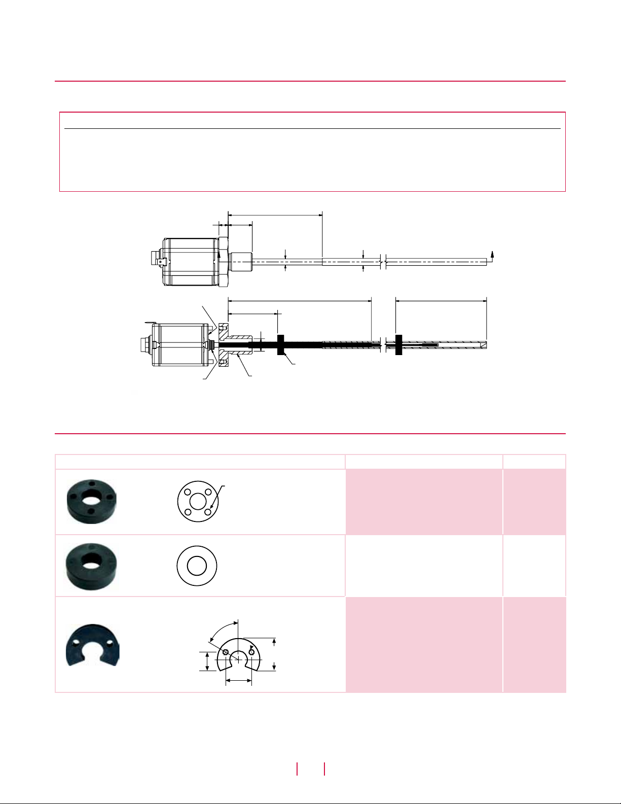
Model RF flexible housing option dimension references
R-SERIES SENSOR WITH MODEL RF FLEXIBLE HOUSING OPTION
Drawing is for reference only, contact applications engineering for tolerance specific information.
Notes:
1. Total sensor length tolerances are:
+8 mm (0.3 in.)/-5mm (0.2 in.) up to 7600 mm (300 in.) stroke length.
+15 mm ((0.6 in.)/-5 mm (0.2 in.) over 7600 mm (300 in.) stroke length.
2. Tolerances of total length do not influence the measuring stroke length.
97 mm (3.8 in.)
Heat shrink sleeve
10 mm (0.38 in.)
25 mm (0.98 in.)
7 mm (0.29 in.)
A
94 mm (3.70 in.)
Dead zone
SECTION A-A
Face seal
O-Ring
Red grommet
Seal
A
6 mm (0.25 in.)
96 mm (3.8 in.) Rigid section
13 mm
(0.51 in.) dia.
Thread 3/4 - 16 UNF - 3A
51 mm (2 in.)
Position magnet
or M18 x 1.5
Null
Figure 1. R-Series Model RF flexible housing dimension reference
Standard magnet selections (Model RF)
POSITION MAGNET SELECTIONS (Drawing dimensions are for reference only)
Magnet and magnet dimensions Description Part number
Standard ring magnet
I.D.: 13.5 mm (0.53 in.)
O.D.: 33 mm (1.3 in.)
Thickness: 8 mm (0.3 in.)
Operating temperature:
- 40 °C to 100 °C
Ring magnet
I.D.: 13.5 mm (0.53 in.)
O.D.: 25.4 mm (1 in.)
Thickness: 8 mm (0.3 in.)
Operating temperature:
- 40 °C to 100 °C
Open-ring magnet, Style M
I.D.: 13.5 mm (0.53 in.)
O.D.: 33 mm (1.3 in.)
Thickness: 8 mm (0.3 in.)
Operating temperature:
- 40 °C to 100 °C
This magnet may influence the sensor
performance specifications for some
applications.
201542-2
400533
251416-2
14 mm
(0.55 in.)
4 Holes
Each 4.3 mm (0.17 in.) dia.
90° apart on
24 mm (0.94 in.) dia.
2 Holes
60°
21 mm
(0.81 in.)
Each 4.3 mm
(0.17 in.) dia. on
24 mm (0.94 in.) dia.
25 mm
(0.97 in.)
MTS Sensors
3
R-Series Temposonics® Linear-Position Sensors - Model RF Flexible Housing Option
Product Data Sheet, Document Part No.: 551081, Revision B 10/11
 Loading...