

MTS Sensors Temposonics R- Ethernet/IP Operation Manual
Temposonics
®
Magnetostrictive Linear Position Sensors
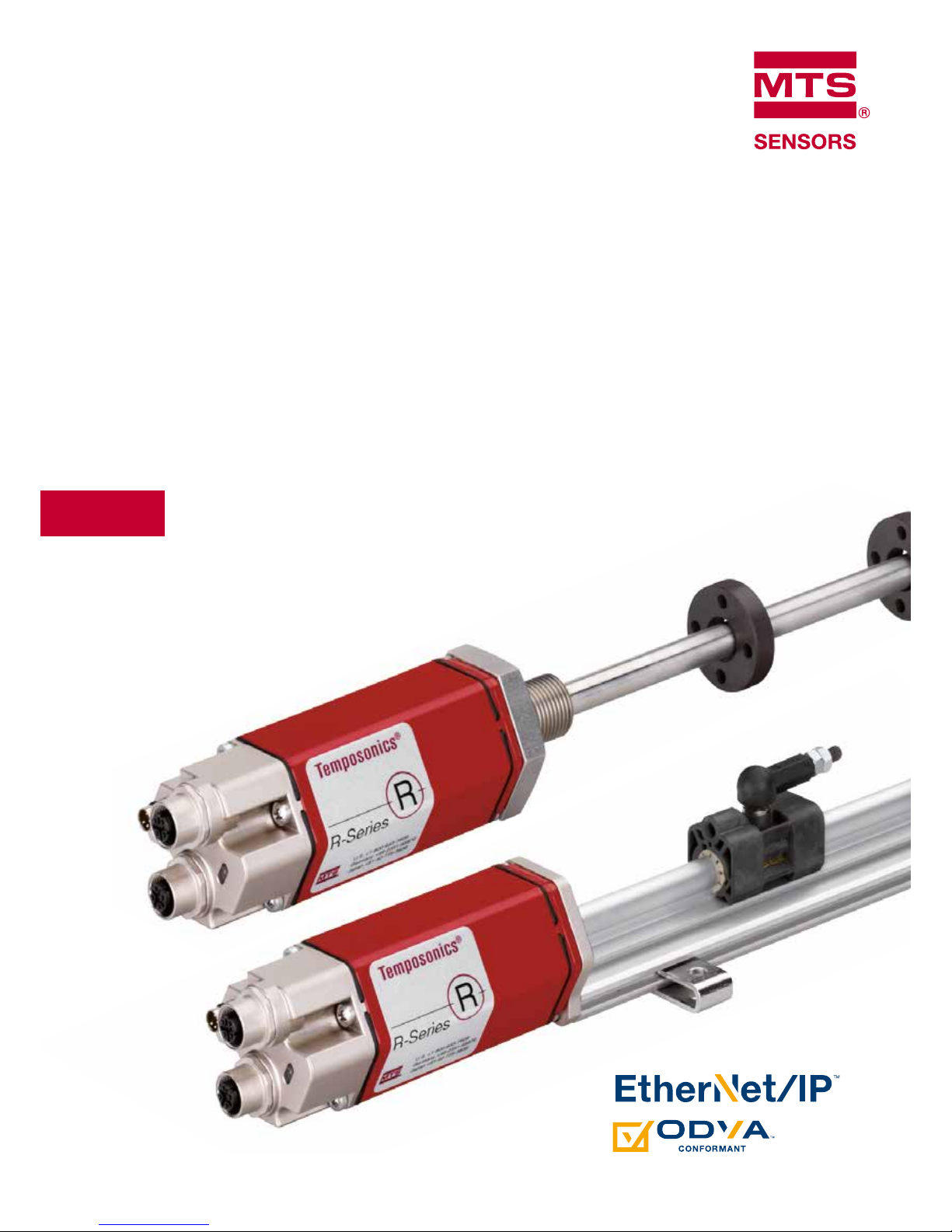
R-Series Ethernet/IP
TM
Operation Manual

Temposonics® R-Series EtherNet/IP
TM
Operation Manual
I 2 I
1/ The term qualified technical personnel characterizes persons who:
– are familiar with the safety concepts of automation technology applicable to the
particular project,
– are competent in the field of EMC,
1/ – have received adequate training for commissioning and service operations
– are familiar with the operation of the device and know the information required for
correct operation provided in the product documentation.
1. Introduction
1.1 Purpose and use of this manual
The content of this technical documentation and of its various annexes is intended to provide information on mounting, installation and
commissioning by qualified automation personnel
1
or instructed service technicians who are familiar with the project planning and dealing
with Temposonics
®
sensors.
1.2 Used symbols and warnings
Warnings are intended for your personal safety and for avoidance of
damage to the described product or connected devices. In this documentation, safety information and warnings to avoid dangers that
might affect the life and health of operating or service personnel or
cause material damage are highlighted by the preceding pictogram,
which is defined below.
2. Safety instructions
2.1 Intended use
This product may be used only for the applications provided under
item 1 and item 2 and only in conjunction with the third-party devices
and components recommended or approved by MTS Sensors. As a
prerequisite of proper and safe operation, the product requires correct
transport, storage, mounting and commissioning and must be operated with utmost care.
1. The sensor systems of all Temposonics
®
series are intended exclusively for measurement tasks encountered in industrial, commercial
and laboratory applications. The sensors are considered as system
accessories and must be connected to suitable evaluation electronics, e.g. a PLC, IPC, indicator or other electronic control unit.
2. The position sensors must be used only in technically safe condition.
To maintain this condition and to ensure safe operation, installation,
connection and service work may be performed only
by qualified technical personnel.
Before starting the operation of Temposonics® sensors read this
documentation thoroughly and follow the safety information.
Symbol Meaning
NOTICE
This symbol is used to point to situations
that may lead to material damage, but not to
personal injury.
Table of contents
1. Introduction ........................................................... 2
1.1 Purpose and use of this manual .......................................... 2
1.2 Used symbols and warnings ............................................... 2
2. Safety instructions................................................... 2
2.1 Intended use ........................................................................ 2
2.2 Forseeable misuse ............................................................... 3
2.3 Installation, commissioning and operation .......................... 3
2.4 Safety instructions for use in explosion-hazardous areas ... 3
2.5 Warranty
............................................................................. 3
2.6 Return ................................................................................. 3
3. Identication ......................................................... 4
3.1 Order structure of R-Series RP ........................................... 4
3.2 Order structure of R-Series RH ........................................... 5
3.3 Order structure of R-Series RD4 ......................................... 6
3.4 Order structure of R-Series RF ............................................ 7
3.5 Nameplate (example) .......................................................... 8
3.6 Approvals ............................................................................ 8
3.7 Scope of delivery ................................................................. 8
4. Product description and commissioning ......................... 8
4.1 Functionality and system design ......................................... 8
4.2 Styles and installation of R-Series RP ................................. 9
4.3 Styles and installation of R-Series RH ............................... 11
4.4 Styles and installation of R-Series RD4 ............................. 13
4.5 Styles and installation of R-Series RF ................................ 19
4.6 Electrical connections ........................................................ 22
4.7 Accessories ...................................................................... 23
5. Operation ............................................................ 24
5.1 Getting started ................................................................... 24
6. IP Address Conguration .......................................... 24
6.1 Set the IP address of the sensor ....................................... 25
7. Integration in RSLogix5000 ....................................... 26
7.1 Install the MTS EtherNet/IP EDS file .................................. 28
7.2 Add sensor to I/O configuration using EDS file ................. 28
7.3 Add sensor to I/O configuration w/o using EDS file ........... 29
7.5 Verify Generic EtherNet Module......................................... 30
7.6 Controller tags configuration data ..................................... 31
8. Maintenance and troubleshooting ............................... 34
8.1 Error conditions, troubleshooting ...................................... 34
8.2 Maintenance ...................................................................... 34
8.3 Repair ................................................................................ 34
8.4 List of spare parts ............................................................. 34
8.5 Transport and storage ....................................................... 34
9. Technical data ....................................................... 35
0. Annex ................................................................. 36
1. Appendix A - Sensor Reset ........................................ 37
2. Appendix B - Port Details .......................................... 38
1
1
1
Temposonics® R-Series EtherNet/IP
TM
Operation Manual
I 3 I
2/ see also applicable MTS Sales and supply conditions, e.g. under www.mtssensors.com
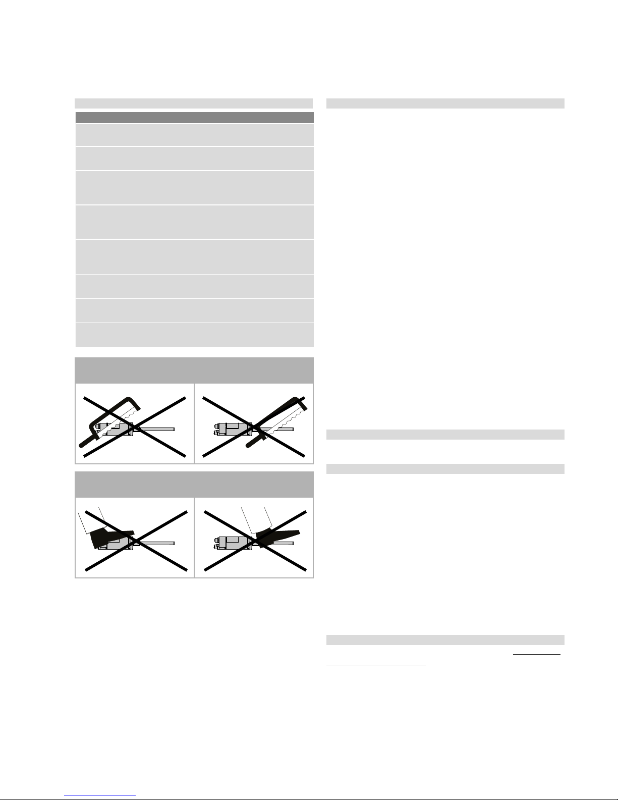
Do not reprocess the sensor afterwards.
The sensor might be damaged.
Do not step on the sensor.
The sensor might be damaged.
2.2 Forseeable misuse 2.3 Installation, commissioning and operation
The position sensors must be used only in technically safe condition.
To maintain this condition and to ensure safe operation, installation,
connection and service work may be performed only by qualified technical personnel.
If danger of injury to persons or of damage to operating equipment
is caused by sensor failure or malfunction, additional safety measures
such as plausibility checks, limit switches, EMERGENCY STOP systems, protective devices etc. are required. In the event of trouble,
shut down the sensor and protect it against accidental operation.
Safety instructions for commissioning
To maintain the sensor operability, it is mandatory to follow the instructions given below.
1. Protect the sensor against mechanical damage during installation
and operation.
2. Do not open or dismantle the sensor.
3. Connect the sensor very carefully and pay attention to the polarity
of connections and power supply.
4. Use only approved power supplies.
5. It is indispensable to ensure that the specified permissible limit
values of the sensor for supply voltage, environmental conditions,
etc. are met.
6. Check the function of the sensor regularly and provide documentation of the checks.
7. Before system switch-on, ensure that nobody’s safety is jeopardized by starting machines.
2.4 Safety instructions for use in explosion-hazardous areas
The sensor is not suitable for operation in explosion-hazarded areas.
2.5 Warranty
2
MTS Sensors grants a warranty period for the Temposonics
®
position sensors and supplied accessories relating to material defects and
faults that occur despite correct use in accordance with the intended
application
2
. The MTS Sensors obligation is limited to repair or replacement of any defective part of the unit. No warranty can be taken
for defects that are due to improper use or above average stress of the
product, as well as for wear parts. Under no circumstances will MTS
Sensors accept liability in the event of offense against the warranty
rules, no matter if these have been assured or expected, even in case
of fault or negligence of the company.
MTS Sensors explicitly excludes any further warranties. Neither the
company’s representatives, agents, dealers nor employees are authorized to in- crease or change the scope of warranty.
2.6 Return
For diagnostic purposes, the sensor can be returned to MTS Sensors
or an authorized repair facility. Any shipment cost will be borne by the
sender
2
. For a corresponding form, see chapter 9 (Annex).
Forseeable misuse Consequence
Wrong sensor connection
The sensor does not work
properly or will be destroyed
Operate the sensor out off the
operating temperature
No signal output
The sensor can be damaged
Power supply is out of the
defined range
Signal output is wrong/
no signal output/
the sensor will be damaged
Position measurement is
influenced by an external
magnetic field
Signal output is wrong
Cables are damaged
Short circuit – the sensor can
be destroyed/sensor does not
respond
Magnet spacers are missing/
are installed in the wrong order
Error in position measurement
Wrong connection
of ground/shield
Signal output is disturbed
The electronics can be damaged
Use of a magnet that is not
certified by MTS Sensors
Error in position measurement

Temposonics® R-Series EtherNet/IP
TM
Operation Manual
I 4 I
3. Identication
3.1 Order structure of R-Series RP
Temposonics
®
order code
a Sensor model
R P
Profile
b Design
S
Magnet slider, joint on top (Part number: 252182)
V
Magnet slider, joint at front (Part number: 252184)
M
U-magnet, OD33 (Part number: 251416-2)
d Connection type
D 5 6
2 × 4 pin M12 female, 1 × 4 pin M8 male
e Operation voltage
1
+24 VDC (−15 / +20 %)
f Output
N 1 0 1
EtherNet/IP™
*/ Non Standard stroke lengths are available; must be encoded in 5 mm / 0.1 in. increments
3/ Note: Please specify magnet numbers for your sensing application and order separately
Optional: for multi-position measurement only
(Order additional magnets seperately)
g Magnet number for multi-position measurement
3
Z X X
02…20 magnets
c Stroke length
X X X X M
0025…5080 mm
X X X X
U
001…200 in.
Standard stroke length (mm)*
Stroke length Ordering steps
25 … 500 mm 25 mm
500…2500 mm 50 mm
2500…5080 mm 100 mm
Standard stroke length (in.)*
Stroke length Ordering steps
1 … 20 in. 1 in.
20…100 in. 2 in.
100…200 in. 4 in.
.
1 2 3 4 5 6 7 8 9 10 11 12 13 14 15 16 17 18 19
R P
D 5 6
1
N 1 0
1
a b c d e
f
g

Temposonics® R-Series EtherNet/IP
TM
Operation Manual
I 5 I
3.2 Order structure of R-Series RH
*/ Non Standard stroke lengths are available; must be encoded in 5 mm / 0.1 in. increments
4/ Note: Please specify magnet numbers for your sensing application and order separately
Temposonics® order code
a Sensor model
R H
Rod
b Design
M
Flange M18×1.5 (Standard)
V
Flange M18×1.5 with Fluoroelastomer housing-seal
D
Flange M18×1.5 bushing on rod end
R
Flange M18×1.5 thread M4 at rod end
J
Flange M22×1.5 rod Ø 12.7 mm, 800 bar
S
Flange M¾"×16UNF - 3A
B
B Sensor cartridge only
(no flange or pressure tube, stroke length <1830 mm (72 in.))
d Connection type
D 5 6
2 × 4 pin M12 female, 1 × 4 pin M8 male
e Operation voltage
1
+24 VDC (−15 / +20 %)
c Stroke length
X X X X M
0025…7620 mm
X X X X
U
001…300 in.
Standard stroke length (mm)*
Stroke length Ordering steps
25 … 500 mm 5 mm
500 … 750 mm 10 mm
750…1000 mm 25 mm
1000…2500 mm 50 mm
2500…5080 mm 100 mm
5000…7620 mm 250 mm
Standard stroke length (in.)*
Stroke length Ordering steps
1 … 20 in. 0.2 in.
20 … 30 in. 0.4 in.
30 … 40 in. 1 in.
40…100 in. 2 in.
100…200 in. 4 in.
200…300 in. 10 in.
.
f Output
N 1 0 1
EtherNet/IP™
Optional: for multi-position measurement only
(Order additional magnets seperately)
g Magnet number for multi-position measurement
4
Z X X
02…20 magnets
1 2 3 4 5 6 7 8 9 10 11 12 13 14 15 16 17 18 19
R H
D 5 6
1
N 1 0
1
a b c d e
f
g

Temposonics® R-Series EtherNet/IP
TM
Operation Manual
I 6 I
3.3 Order structure of R-Series RD4
Temposonics
®
order code
b Design
S
Pressure fit flange
M
Threaded flange M18×1.5-6g, AF23
C
Threaded flange M18×1.5-6g, AF46
T Threaded flange ¾“–16UNF–3A.
D Threaded flange ¾“–16UNF–3A.
d Sensor electronics
S
Side cable entry
B
Bottom cable entry
a Sensor model
R D
4
Detachable sensor electronics
c Integral cable of sensor rod
For side cable entry:
D 1 PUR-cable, length 250 mm (9.8 in.)
D 2 PUR-cable, length 400 mm (15.7 in.)
D 3 PUR-cable, length 600 mm (23.6 in.)
For bottom cable entry:
R 2 Single wires with flat connector, length 65 mm (2.6 in.)
R 4 Single wires with flat connector, length 170 mm (6.7 in.)
R 5 Single wires with flat connector, length 230 mm (9.1 in.)
R 6 Single wires with flat connector, length 350 mm (13.8 in.)
*/ Non Standard stroke lengths are available; must be encoded in 5 mm / 0.1 in. increments
5/ Note: Please specify magnet numbers for your sensing application and order separately
Standard stroke length (mm)*
Stroke length Ordering steps
25 … 500 mm 5 mm
500 … 750 mm 10 mm
750…1000 mm 25 mm
1000…2500 mm 50 mm
2500…5080 mm 100 mm
Standard stroke length (in.)*
Stroke length Ordering steps
1…20 in. 0.2 in.
20…30 in. 0.4 in.
30…40 in. 1 in.
40…100 in. 2 in.
100…200 in. 4 in.
c Stroke length
X X X X M
Flange M & C: 0025…5080 mm
Flange S: 0025…2540 mm
X X X X
U
Flange M & C: 001…200 in.
Flange S: 001…100 in.
.
f Connection type
D 5 6
2 × 4 pin M12 female, 1 × 4 pin M8 male
f Output
N 1 0 1
EtherNet/IP™
Optional: for multi-position measurement only
(Order additional magnets seperately)
g Magnet number for multi-position measurement
5
Z X X
02…20 magnets
1 2 3 4 5 6 7 8 9 10 11 12 13 14 15 16 17 18 19 20 21 22
R D 4 D 5 6
N 1 0 1
a b c d d g
f
g

Temposonics® R-Series EtherNet/IP
TM
Operation Manual
I 7 I
3.4 Order structure of R-Series RF
Temposonics
®
order code
a Sensor model
R F
Flexible sensor rod
b Design
C
Basic sensor
M Flange M18×1.5-6g
S
Flange ¾"×16UNF-3A
e Operation voltage
1
+24 VDC (−15 / +20 %)
*/ Non Standard stroke lengths are available; must be encoded in 5 mm / 0.1 in. increments
6/ Note: Please specify magnet numbers for your sensing application and order separately
f Connection type
D 5 6
2 × 4 pin M12 female, 1 × 4 pin M8 male
c Stroke length (Longer strokes are available. Contact applications engineering for details.)
X X X X X
M
00100…10060 mm
X X X X X
U
0004.0…0396.0 in.
Standard stroke length (mm)*
Stroke length Ordering steps
100 … 1000 mm 50 mm
1000…10060 mm 250 mm
Standard stroke length (in.)*
Stroke length Ordering steps
4 … 40 in. 2 in.
40…396 in. 10 in.
f Output
N 1 0 1
EtherNet/IP™
Optional: for multi-position measurement only
(Order additional magnets seperately)
g Magnet number for multi-position measurement
6
Z X X
02…20 magnets
1 2 3 4 5 6 7 8 9 10 11 12 13 14 15 16 17 18 19 20
R F D 5 6
1
N 1 0 1
a b c g e
f
g
Temposonics® R-Series EtherNet/IP
TM
Operation Manual
I 8 I
RD4CD1S1250MD56N101Z02
MAC ID: 00-03-CA-00-2D-5F
S/N: 90595059
GRD: 9.1044 uS/In | 2789.85 m/s
Sensor model
Design
Measuring range (e.g. 1250 mm)
Connection type
Output version
Magnet number
Part No.
MAC adress
Gradient
Serial number
Sensor electronics
3.7 Scope of delivery
R-Series RP (prole):
Sensor, Position magnet, 2 mounting clamps up to 1250 mm (49 in.)
+ 1 clamp for each 500 mm (20 in.)
R-Series RH (rod):
Sensor, O-ring
4. Product description and commissioning
4.1 Functionality and system design
Product designation
– Position sensor Temposonics
®
R-Series
Construction series
– Temposonics® R-Series RP/RH/RD4/RF
– Stroke length: RP 25…5080 mm (1…200 in.)
RH 25…7620 mm (1…300 in.)
RD4 25…5080 mm (1…200 in.)
RF 100…10060 mm (4…396 in.)*
– Output signal: EtherNet/IP™
Application
The Temposonics
®
sensor is used for measurement and conversion
of the length (position) variable in the field of automated system and
mechanical engineering.
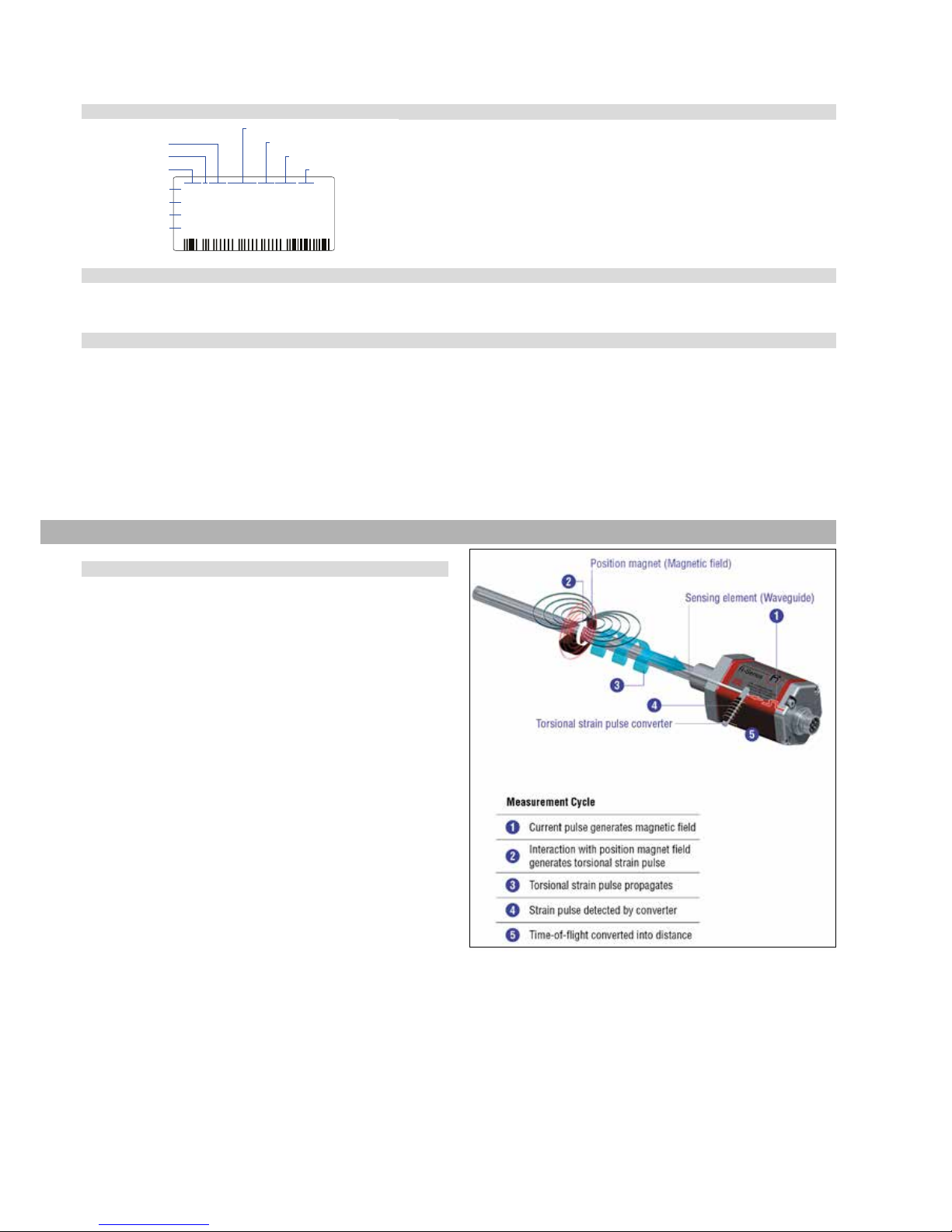
Principle of operation and system construction
For position measurement, the absolute, linear Temposonics
®
position
sensors make use of the properties offered by the specially designed
magnetostrictive waveguide. Inside the sensor a torsional strain pulse
is induced in the waveguide by momentary interaction of two magnetic fields. The interaction between these two magnetic fields produces a strain pulse, which is detected by the electronics at the head of
the sensor. One field is produced by a moving position magnet, which
travels along the sensor rod with the waveguide inside. The other field
is generated by a current pulse applied to the waveguide. The position
of the moving magnet is determined precisely by measuring the time
elapsed between the application of the current pulse and the arrival
of the strain pulse at the sensor head. The result is a reliable position
measurement with high accuracy and repeatability.
R-Series RD4 (detached electronics):
RD4-S
Sensor, O-ring, Back-Up ring
RD4-C/M/T/D
Sensor, O-ring
R-Series RF (exible sensor rod):
RF-M / RF-S:
Sensor, Threaded Flange, O-ring
Fig. 1: Principle of operation: Time-based magnetostrictive position sensing principle
Modular mechanical and electronic construction
– The sensor housing protects the sensor element.
– The sensor electronics housing, a rugged aluminum
construction, contains the complete electronic interface with
active signal conditioning.
– The external position magnet is a permanent magnet. Mounted
on the mobile machine part, it travels along the sensing element and
triggers the measurement through the housing wall.
– Depending on the type, the sensor is connected to the controller via a plug.
– The sensor can be connected directly to a control system.
Its electronics generates a strictly position-proportional signal
output between zero and end position.
*/ (Longer strokes available, please contact applications engineering for
details.)
3.5 Nameplate (example)
3.6 Approvals
CE certification (only for RP & RH; RF: The conformity is fulfilled, assumed the wave guide of the sensor is embedded in an EMC-sealed and
grounded housing), EPSG certified, GOST certified, UL/cUL certified (only for RP/RH)
Ağaç isadleme
Temposonics® R-Series EtherNet/IP
TM
Operation Manual
I 9 I
4.2 Styles and installation of R-Series RP
Temposonics
®
RP offers modular construction, flexible mounting configurations and easy installation. Position measurement is non-contact
via two versions of permanent magnets.
• A sliding magnet running in profile housing rails. Connection with the moving machine part is via a ball jointed arm for taking up axial forces.
• A floating magnet, mounted directly on the moving machine part, travels over the profile at a low distance. Its air-gap allows the correction
of small misalignments at installation.
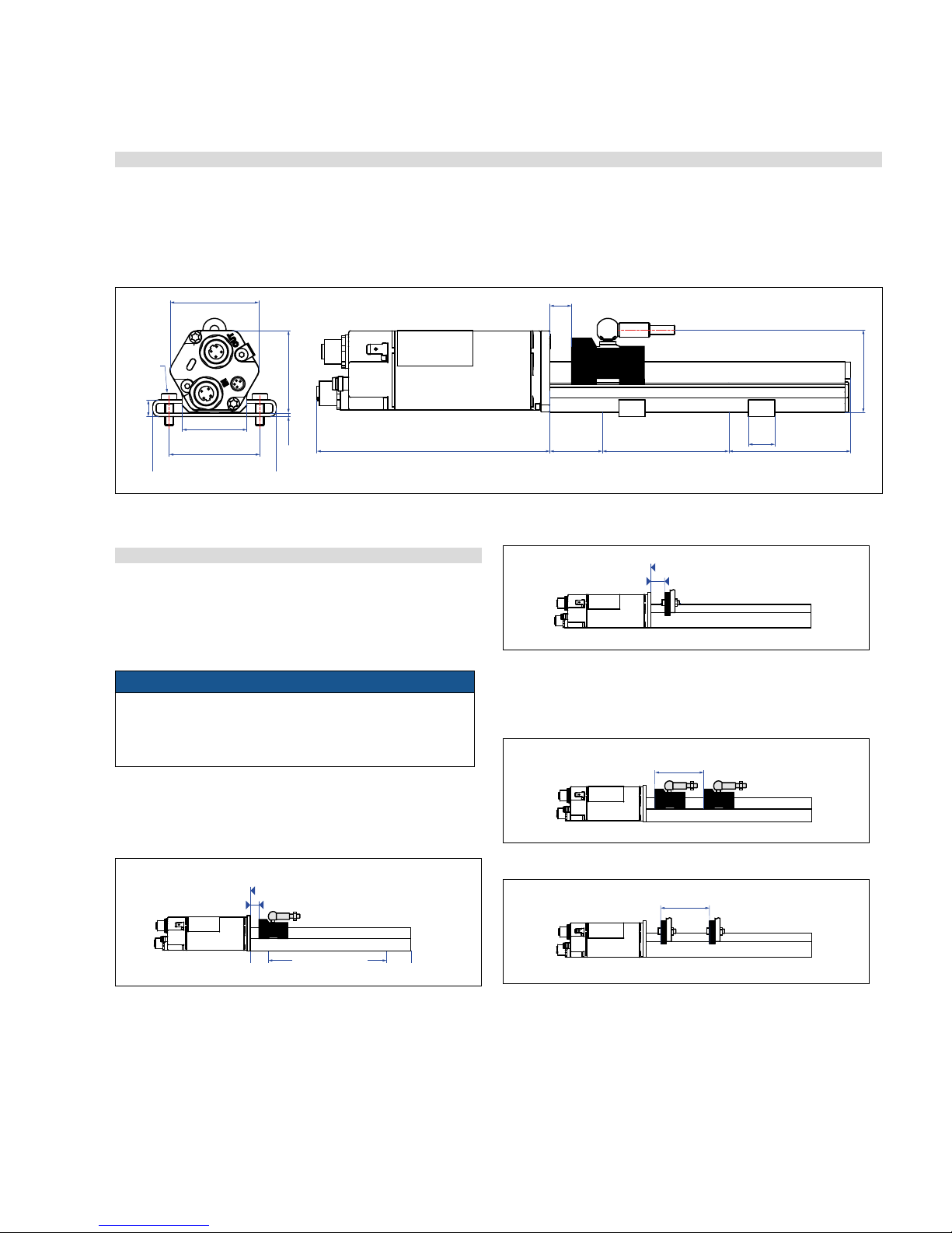
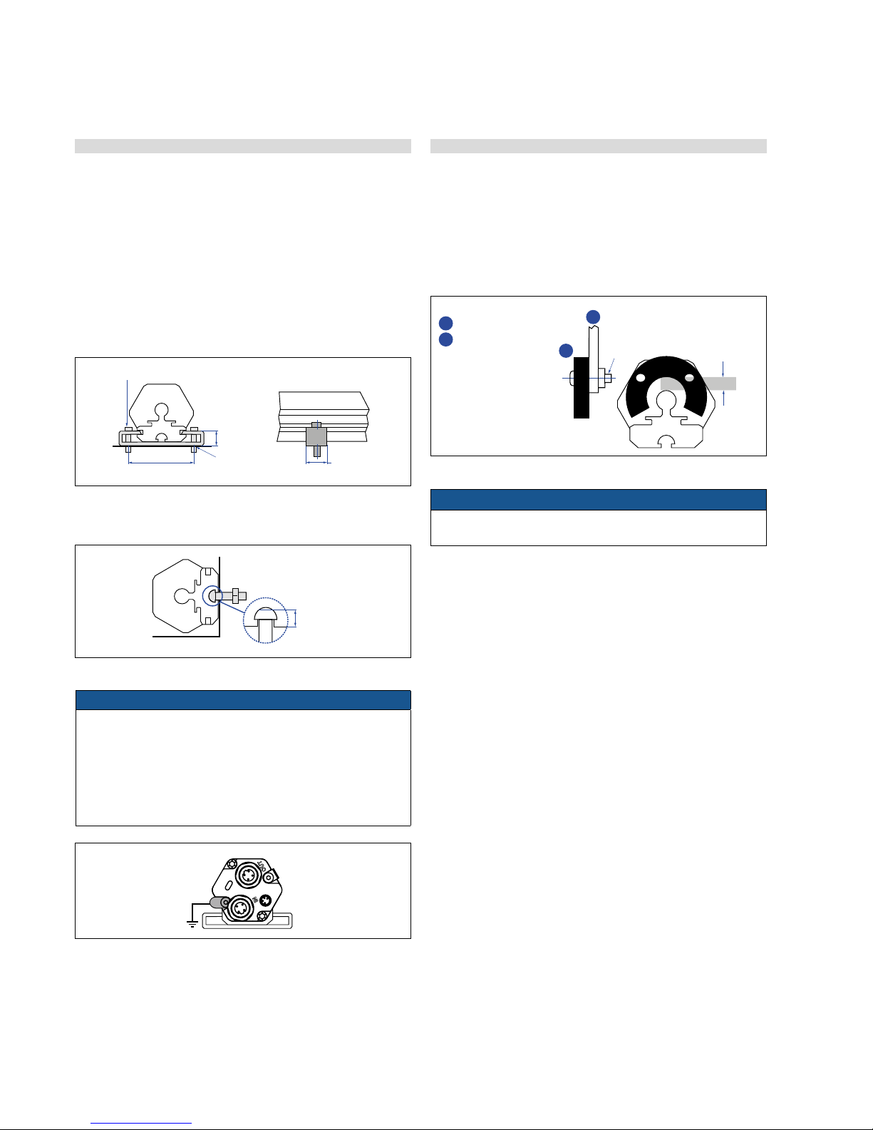
4.2.1 Mounting distances
Active measuring range
The technical data of each sensor is checked as well as documented
and the active stroke length (useful electrical stroke) with its start
and end position is adjusted during final inspection and testing
(see Fig. 2).
NOTICE
On all sensors, the areas left and right of the active stroke length
are provided for mounting and damping of the measuring signal.
They should not be used for measurement, but the active stroke
length can be exceeded without problem.
Mechanical zero
To ensure that the entire measuring range can be used electrically,
the position magnet must be mounted mechanically as follows:
Multi-position measurement
The minimum distance between the magnets is 75 mm (3 in.).
Fig. 3: Temposonics® profile with magnet slider
Fig. 2: RP Style dimensional drawing
Fig. 4: Temposonics
®
profile with U-magnet
Fig. 5: Minimum distance for multi position measurement with magnet slider
Fig. 6: Temposonics
®
profile with U-magnet
Controlling design dimensions are always in metric unitsand measurements in ( ) are in inches
12
(0.47)
Start position
Magnet slider
Reference edge of mounting
28
(1.1)
Measuring range
66
(2.6)
12
(0.47)
Start position
Magnet slider
U-magnet
Reference edge of mounting
Start position
Reference edge of mounting
28
(1.1)
Measuring range
66
(2.6)
28
(1.1)
minimum 75 (3)
minimum 75 (3)
minimum 75 (3)
50
(1.97)
35.6
(1.4)
2
(0.08)
45
(1.77)
12
(0.47)
66
(2.6)
14.5
(0.57)
45.4
(1.79)
129
(5.07)
28
(1.1)
Measuring range
25…5080
(1…200)
49
(1.93)
9
(0.36)
Ø 5.5 (0.21)
M5 or #10
screw
Magnet
Controlling design dimensions are always in metric units and measurements in ( ) are in inches
Temposonics® R-Series EtherNet/IP
TM
Operation Manual
I 10 I
4.2.3 Magnet mounting
Mounting the U-magnet
The U-magnet is removable and can be used for profile- and rod-style
sensors. Using a non-magnetizable mounting device is mandatory.
The magnet must not rub against the measuring rod. Alignment errors
are compensated via the air gap.
– Max. surface pressure: 40 N/mm
2
– Max. tightening torque for M4 screws: 1 Nm;
use washer, if necessary
Fig. 10: Mounting device for U-magnet
NOTICE
A maximum permissible air gap of 3 ±1mm (0.12 in.) must not be
exceeded.
3 ±1
(0.12 ± 0.04)
M4
1
2
4.2.2 Installation of RP
The position sensor can be installed in any position. Normally,
the sensor is firmly installed and the position magnet is fastened
to the mobile machine part. Thus it can travel along the measuring
rod contactlessly.
The sensor is fitted on a flat machine surface using the mounting
clamps (fig. 7). A length-dependent number of these clamps are
delivered with the sensor and must be distributed over the profile
at regular distances.
For fastening, we recommend using M5×20 screws to DIN 6912
that shout be tightened with a maximum torque of 5 Nm.
Fig. 7: Mounting clamps with cylinder screw M5×20, fastening torque < 5 Nm
Alternative: If only limited space is available, the profile sensor can be mounted also via
the T-rail in the profile bottom using an M5 T-slot nut or a sliding block (fig. 8).
Fig. 8: T-slot nuts M5
NOTICE
Don’t mount the sensors in the area of strong magnetic or electric
noise fields. Take care to mount the sensor in an axially parallel
position to avoid damaging the carriage, magnet and measuring rod.
The sensor is isolated from the machine ground. For this reason,
earthing via the flat-pin connector on the sensor electronics housing
is indispensable (fig. 9).
50
Bore-Ø
5.5 mm
14.5
max.
5 mm
M5
Fig. 9: Grounding profile sensor
max. 5 Nm
50
(1.97)
9
(0.36)
Bore Ø 5.5
(Ø 0.21)
14.5
(0.57)
5
(0.2)
M5
1
U-magnet
2
Non-magnetic
mounting device
Controlling design dimensions are always in metric units and measurements in ( ) are in inches
Temposonics® R-Series EtherNet/IP
TM
Operation Manual
I 11 I
4.3 Styles and installation of R-Series RH
Temposonics
®
RH with a pressure resistant stainless steel flange and sensing rod. They are suitable in all fluid power cylinders and externally in
all applications where space is a problem. Position measurement is via ring or U-magnets travelling along the sensing rod without any mechanical
contact.
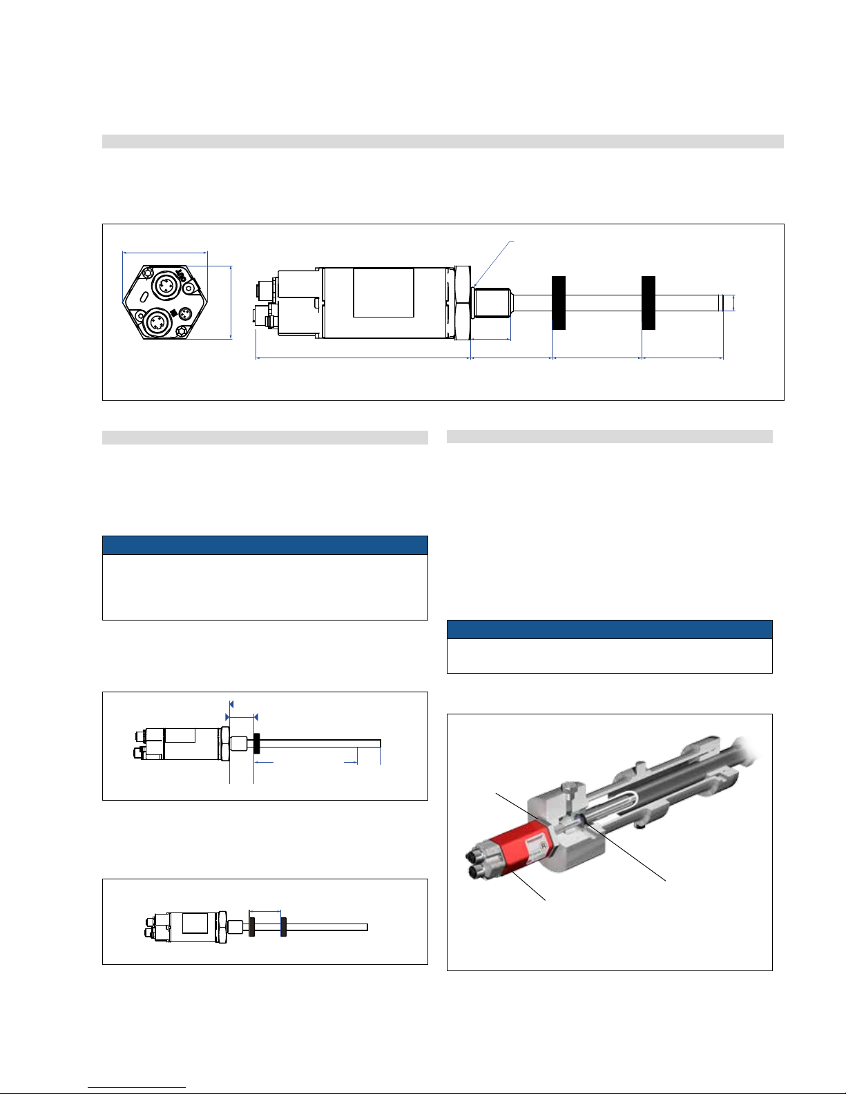
4.3.1 Mounting distances
Active measuring range
The technical data of each sensor is checked as well as documented
and the active stroke length (useful electrical stroke) with its start
and end position is adjusted during final inspection and testing
(see Fig. 11).
NOTICE
On all sensors, the areas left and right of the active stroke length
are provided for mounting and damping of the measuring signal.
They should not be used for measurement, but the active stroke
length can be exceeded without problem.
Mechanical zero
To ensure that the entire measuring range can be used electrically,
the position magnet must be mounted mechanically as follows:
Fig. 12: Temposonics® rod with ring magnet
Fig. 11: RH Style dimensional drawing
4.3.2 Installation of RH
Installation of a rod-style sensor
The rod-style version has been developed for direct stroke
measurement in a fluid cylinder.
– Mounted on the bottom of the piston, the ring magnet travels
over the rod contactlessly and marks the position exactly through
the rod wall.
– Inside the pressure-resistant sensor housing immerging into the
open piston rod, the basic sensor is mounted by means of only
two screws. It is the only part that needs replacing if servicing is
required, i.e. the hydraulic circuit remains closed.
NOTICE
After re-installing, securing the basic sensor screws, e.g. using
Loctite 243, is mandatory.
Basic sensor
The electronics head with sensing
element can be replaced via two M4
screws with a 2.5 mm hexagonal
recess, max. tightening torque 1.3 Nm
Pressure-resistant
sensor housing
In the event of servicing,
the rod with the flange
remains in the cylinder.
Fig. 14: Sensor in fluid cylinder
Position magnet
Rod with inner sensor element immersed in the cylinder
Multi-position measurement
The minimum distance between the magnets is 75 mm (3 in.).
Fig. 13: Minimum distance for multi position measurement
Controlling design dimensions are always in metric units and measurements in ( ) are in inches
12
(0.47)
Start position
Magnet slider
U-magnet
Ring magnet
Reference edge of mounting
Start position
Start position
Reference edge of mounting
Reference edge of mounting
28
(1.1)
Measuring range
Measuring range
66
(2.6)
28
(1.1)
51
(2)
51
(2)
63.5/66*
(2.5/2.6)
minimum 75 (3)
minimum 75 (3)
minimum 75 (3)
50
(1.97)
68
(2.68)
35.6
(1.4)
2
(0.08)
49
45
2
28
Measuring range
25…5080
66
45
(1.77)
12
(0.47)
66
(2.6)
14.5
(0.57)
45.4
(1.79)
129
(5.07)
28
(1.1)
Measuring range
25…5080
(1…200)
49
(1.93)
128
28
50
35.6
68
O-ring
51
(2)
63.5/66*
(2.5/2.6)
Measuring range
25…7620
(1…300)
133
(5.24)
Ø 10
(Ø 0.39)
46
(1.75)
53
(2)
25
(0.98)
*> 5000 mm
Stroke length
Magnet
Magnet
Magnet
Magnet
Controlling design dimensions are always in metric units and measurements in ( ) are in inches
Temposonics® R-Series EtherNet/IP
TM
Operation Manual
I 12 I
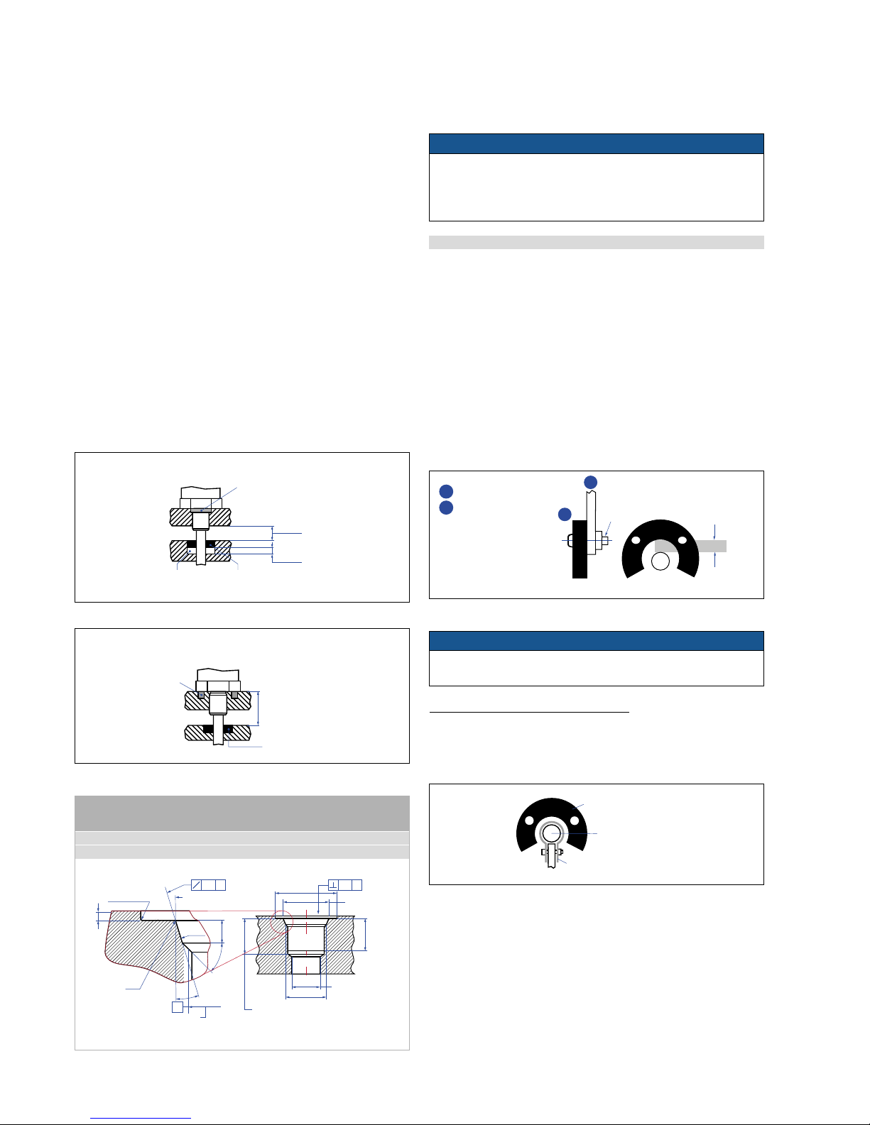
Fig. 15: Installation with non-magnetic material
Fig. 16: Installation with magnetic material
Hydraulics sealing
There are two ways for sealing the flange contact surface:
1. A sealing by using an O-ring (e.g. 22.4×2.65 mm) in a cylinder
bottom groove (fig. 16).
2. A sealing via an 15.3×2.2 mm O-ring (for metric thread flange) or
0.644" x 0.087" O-ring (for SAE thread flange) in the undercut (fig.
15). In this case, a screw hole based on ISO 6149-1 (fig. 17) must be
provided.
– The flange contact surface must be seated completely on the
cylinder mounting surface.
– The cylinder manufacturer determines the pressure-resistant
gasket (copper gasket, O-ring, etc.).
– The position magnet should not rub against the rod.
– The plunger borehole (Ø 10 mm rod: > Ø 13 mm (Ø 0.52 in.) Ø 12.7
mm rod: > 16 mm (0.63 in.)) depends on the pressure and piston
speed.
– The peak pressure should not be exceeded.
– Protect the measuring rod against wear.
Fig. 17: Notice for threaded flange M18×1.5 based on DIN ISO 6149-1
Large stroke lengths from 1 meter (39 in.)
Horizontally installed sensors should be supported mechanically at the
rod end. Longer rods require evenly distributed mechanical support
over the entire length. In this case an U-magnet (see fig. 19) is used
for measurement.
NOTICE
A maximum permissible air gap of 3 ±1mm (0.12 in.) must not be
exceeded.
Fig. 19: Example of sensor support
SW 46
Anziehmoment
≤ 50 Nm
Magnet
Empfohlene
Hydraulik-
abdichtung
Magnet
nicht-magnetisbare
Distanzscheibe
Alternative
Hydraulikdichtung
O-Ring 15,3 x 2,2
U-magnet
Sensor rod
Non-magnetic retaining clip
4.3.3 Magnet mounting
Mounting the ring magnet
Install the magnet using non-magnetizable material for mounting
device, screws, spacers etc.
– Max. permissible surface pressure: 40 N/mm
2
– Max. fastening torque for M4 screws: 1 Nm; use washers, if necessary
Mounting the U-magnet
Using a non-magnetizable mounting device is mandatory. The magnet
must not rub against the measuring rod. Alignment errors are compensated via the air gap.
– Max. surface pressure: 40 N/mm
2
– Max. fastening torque for M4 screws: 1 Nm;
use washer, if necessary
Fig. 18: Mounting device for U-magnet
3 ±1
(0.12 ± 0.04)
M4
1
2
NOTICE
For mounting by means of screws, use only a hexagonal flange
width across flats 46 mm (1.8 in.) below the sensor electronics
housing (electronics) and avoid exceeding the maximum fastening
torque of 50 Nm
(for RH-J: 125 Nm).
1
U-magnet
2
Non-magnetic
mounting device
Controlling design dimensions are always in metric units and measurements in ( ) are in inches
Thread
(d1×P)
d
2
d
3
d4d
5
L
1
L
2
L
3
L4Z°
M18 × 1.5 55 mm 13 mm 24.5 mm 19.8 mm 2.4 mm 28.5 mm 2 mm 26 mm 15°
¾ x 16 See Appendix B
This dimension applies
when tap drill cannot
pass through entire boss
Thread (d
1
×P)
(Reference size)
Applies at Ød
4
A
R 0.4 max.
L
3
L
1
45° ±5°
Ra 3.2
Ød
5
Ra 3.2
Ød
2
Ra 0.2
Ra 0.1
Pitch diameter
Z°
L
2
L
4
A
0.2 A0.2 A
Ød
3
≥ 15
(≥ 0.6)
≥ 3.2 (5 recommended)
(≥ 0.125/0.2)
magnetic
sensor fastening
non-magnetic
spacer
position
magnet
O-ring
O-ring
non-magnetic
sensor fastening
≥ 30
(≥ 1.2)
position
magnet
 Loading...