

MTS Sensors Temposonics R, Temposonics RP, Temposonics RH Datasheet
Temposonics
®
SENSORS
Magnetostrictive, Absolute, Non-contact
Linear-Position Sensors
R-Series Models RP and RH
DeviceNet Output
Data Sheet
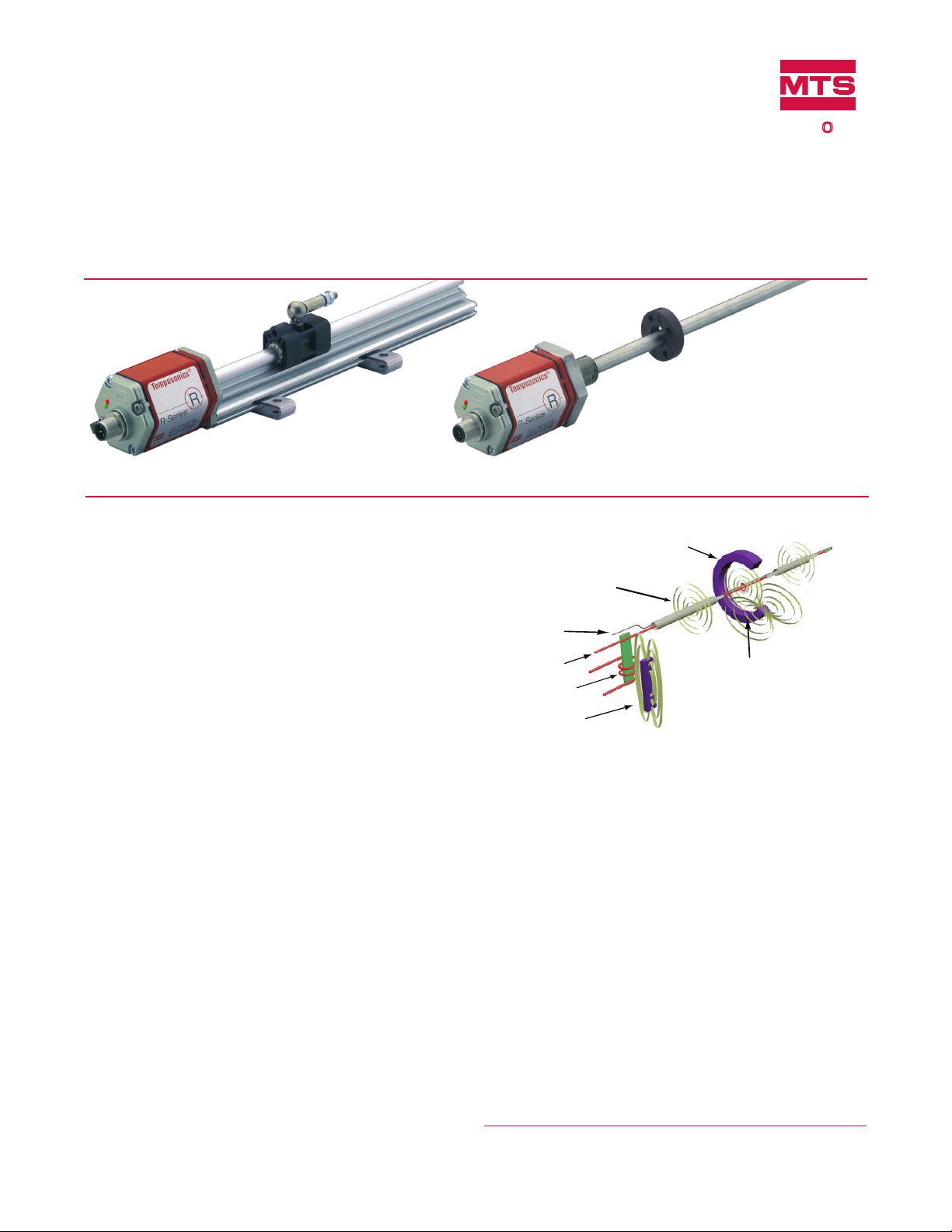
Model RP Prole-style position sensor
FEATURES
Linear, Absolute Measurement
LEDs For Sensor Diagnostics
Superior Accuracy, Resolution down to 2 µm
Non-Contact Sensing Technology
Linearity Deviation Less Than 0.01%
Repeatability Within 0.001%
Direct DeviceNet Output
BENEFITS
Rugged Industrial Sensor
Cost-effective Communications Network linking Industrial
Measurement and Control Devices
Interface Up to 64 Devices using one cable
APPLICATIONS
Continuous Operation In Harsh Industrial Conditions
High Pressure Conditions
TYPICAL INDUSTRIES
Factory Automation
Fluid Power
Plastic Injection and Blow Molding
Material Handling and Packaging
Document Part Number
550651 Revision F
Model RH Rod-style position sensor
Time-based Magnetostrictive position sensing principle
Movable position magnet
Magnetic field encompasses
entire waveguide - generated
by the interrogation pulse
Interrogation
Return wire
Waveguide
Strain-Pulse detector
Bias magnet
Benefits of Magnetostriction
Temposonics linear-position sensors use the time-based
magnetostrictive position sensing principle developed by MTS.
Within the sensing element, a sonic-strain pulse is induced in a
specially designed magnetostrictive waveguide by the momentary
interaction of two magnetic fields. One field comes from a moveable
permanent magnet that passes along the outside of the sensor. The
other field comes from an “interrogation” current pulse applied along
the waveguide. The resulting strain pulse travels at sonic speed along
the waveguide and is detected at the head of the sensing element.
The position of the magnet is determined with high precision and
speed by accurately measuring the elapsed time between the application of the interrogation pulse and the arrival of the resulting strain
pulse with a high-speed counter. The elapsed time measurement is
directly proportional to the position of the permanent magnet and is
an absolute value. Therefore, the sensor's output signal corresponds
to absolute position, instead of incremental, and never requires
recalibration or re-homing after a power loss. Absolute, non-contact
sensing eliminates wear, and guarantees the best durability and
output repeatability.
All specifications are subject to change. Contact MTS for specifications and
engineering drawings that are critical to your application. Drawings contained
in this document are for reference only. Go to http://www.mtssensors.com for
the latest support documentation and related media.
Magnetic field from
position magnet
Interaction of magnetic
fields causes waveguide to
generate a strain pulse
®

Product Overview and Specifications
Product overview
R-Series model RH and RP sensors are extremely robust and are
ideal for continuous operation under harsh industrial conditions.
MTS offers two standard sensor housings, rod and profile extrusion.
The rod housing is capable of withstanding high pressures such as
those found in hydraulic cylinders.
The profile extrusion housing provides convenient mounting options
and captive sliding magnets which utilize slide bearings of special
material that reduce friction, and help mitigate dirt build up. The
sensor head contains the active signal conditioning and a complete
integrated electronics interface. Double shielding is used to ensure
EMI protection for unsurpassed reliability and operating safety.
Product specifications
Parameters Specifications
OUTPUT
Measured output
variable: Position
Resolution: 2 µm or 5 µm
Update times: 0.5 ms up to 1200 mm,
1.0 ms up to 2400 mm,
2.0 ms up to 4800 mm,
4.0 ms up to 7600 mm stroke length
Linearity
deviation: < ± 0.01% full stroke (minimum ± 40 µm)
Repeatability: < ± 0.001% full stroke
(minimum ± 2.5 µm)
Hysteresis: < 4 µm
Output:
Baud rate, kBit/s:
Cable length, m:
Stroke length:
ELECTRONICS
Operating voltage: +24 Vdc nominal: -15% or +20%*
* UL Recognition requires an approved power supply with energy limitation UL 61010-
1), or Class 2 rating according to the National Electrical Code (USA) / Canadian
Electrical Code.
** The IP rating is not part of the UL Recognition.
Interface:
CAN-Fieldbus system ISO DIS 11898
Data protocol DeviceNet release 2.0
500 250 125
<100 <250 <500
Sensors will be supplied with ordered Baud rate
which can be changed by the customer.
Range (Profile style):
25 mm to 5080 mm (1 in. to 200 in.)
Range (Rod style):
25 mm to 7620 mm (1 in. to 300 in.)
Polarity protection: up to -30 Vdc
Overvoltage protection: up to 36 Vdc
Current drain: 90 mA typical
Dielectric withstand voltage: 500 Vdc
(DC ground to machine ground)
Controller Area Network (CAN) is a standard for device level communications and the foundation of fieldbus systems like DeviceNet,
CANopen and CANbus.These fieldbus systems can provide high
speed transmission appropriate for position indication and for motion control in industrial applications.
DeviceNet allows users to interface up to 64 devices using a single
cable, thus eliminating the need for conventional methods of multiple
wire runs. DeviceNet provides a way to define how, and in which
priority, data will be transmitted over the network. The result is a
lower complexity, cost-effective communications network linking
industrial measurement and control devices. Together, the open
DeviceNet protocol and the MTS “smart” R-Series sensors offer an
effective, high-precision data transfer system that is well suited for
industrial automation.
Parameters Specifications
ENVIRONMENTAL
Operating
conditions:
Operating temperature:
-40 °C (-40 °F) to +75 °C (+167 °F)
Relative humidity: 90% no condensation
Temperature coefficient: 15 ppm/ °C
EMC test: Electromagnetic emission:
IEC/EN 50081-1
Electromagnetic susceptibility:
IEC/EN 50082-2, IEC/EN 61000-4-2/3/4/6,
level 3/4 criterium A, CE qualified
Shock rating: 100 g (single hit)/IEC standard 68-2-27
(survivability)
Vibration rating: 15 g / 10 to 2000 Hz / IEC standard 68-2-6
WIRING
Connection type: 5-pin male D51 DeviceNet connector
PROFILE STYLE SENSOR (MODEL RP)
Electronic head: Aluminum housing with diagnostic LED
display (LEDs located beside connector/
cable exit)
Sealing: IP 65**
Sensor extrusion: Aluminum (Temposonics profile style)
Mounting: Any orientation. Adjustable mounting
feet or T-slot nut (M5 threads) in bottom
groove
Magnet types: Captive-sliding magnet or open-ring
magnet
ROD STYLE SENSOR (MODEL RH)
Electronic head: Aluminum housing with diagnostic LED
display (LEDs located beside connector/
cable exit)
Sealing: IP 67 or IP 68 for integral cable models**
Sensor rod: 304L stainless steel
Operating
pressure:
350 bar static, 690 bar peak
(5000 psi static, 10,000 psi peak)
Mounting: Any orientation. Threaded flange M18 x 1.5
or 3/4 - 16 UNF-3A
Typical
mounting torque: 45 N-m (33 ft. - lbs.)
Magnet types: Ring magnet, open-ring magnet, or
magnet float
R-Series Models RP and RH Temposonics® Linear-Position Sensors - DeviceNet Output
Product Data Sheet, Document Part No.: 550651 Revision F (EN) 05/2014 2
MTS Sensors
Enhanced monitoring and diagnostics
9 mm
DeviceNet Protocol, Programmability, Enhanced Monitoring,
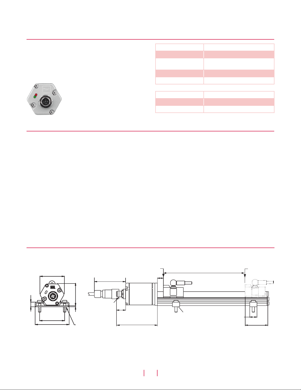
Diagnostics and Model RP sensor dimension references
SENSOR STATUS AND DIAGNOSTIC DISPLAY
Integrated diagnostic LEDs (green/red), located beside sensor connector (see ‘Figure 1’), provide basic visual monitoring
for normal sensor operation and DeviceNet communications.
Diagnostic display LEDs indicate two modes, Network and Module
status as described in ‘Table 1’.
Figure 1. R-Series sensor Integrated diagnostic LEDs
DeviceNet protocol
R-Series models RP and RH linear-position sensors as slave devices
fulfill all requirements of the CANbus (ISO 11898) standard. The sensors electronics and integrated software implement the DeviceNet
protocol to convert the displacement measurements into bus
oriented outputs and transfer this data directly to the controller.The
DeviceNet protocol is appropriate for serial data transfer up to 500
kBit/sec.
When using the DeviceNet protocol with R-series sensors, functionality always includes but is not limited to the following:
• Position
• Error Detection
• Polling & bit-strobe communications modes
PLUG AND PLAY
R-Series sensors with DeviceNet output can be directly connected
to a DeviceNet network. The plug and play design makes installation
quick and easy. The sensor acts as a “slave” device that transmits
Network Status LED Operation status/mode
Green Normal function (operation mode)
Green Flashing Waiting for instructions from
DeviceNet master
Red Initialization error
Red Flashing No answer from DeviceNet master
Module Status LED Operation status/mode
Green Normal function (operation mode)
Red Magnet not detected
Table 1. Diagnostic display indicator modes
its position and status data upon request to the “master” device
such as a PLC or IPC. After initial system configuration, the user is
not required to have extensive knowledge concerning network timing and sensor technology to execute operations within DeviceNet
environment. Sensor-specific parameters are installed into the
network using the Electronic Data Sheet (EDS). To obtain the EDS,
go to www.mtssensors.com.
There are only two programmable parameters, which are, the node
identifier and the baud rate. If desired, a PC programming tool,
such as DeviceNet Manager offered by Allen Bradley, can be used
to change their values. The node identifier is factory set at node 63.
The selected baud rate is shown in the sensor's model number.
Note that the sensor will only be recognized on a network running
at the same baud rate.
Model RP profile-style sensor dimension references
MODEL RP, PROFILE-STYLE SENSOR WITH CAPTIVE-SLIDING MAGNET
Drawing is for reference only, contact applications engineering for tolerance specific information.
Beginning of stroke - ‘Null’ position
(0.36 in.)
50 mm (1.97 in.)
68 mm (2.68 in.)
49 mm
(1.9 in.)
D51
45 mm
(1.77 in.)
Metal connector
2 mm
(0.07 in.)
5.5 mm (0.21 in.)
for M5 or #10 screw
63 mm
(2.5 in.)
12 mm (0.47 in.)
Sensor head
18 mm
(0.7 in.)
81 mm
(3.2 in.)
integral connector option
Figure 2. R-Series Model RP Profile-style sensor dimension reference (Shown with the D51 integral connector option)
MTS Sensors
3
R-Series Models RP and RH Temposonics® Linear-Position Sensors - DeviceNet Output
Stroke length
Captive-sliding magnet
Mounting foot, moveable
(part no.: 400802)
Product Data Sheet, Document Part No.: 550651 Revision F (EN) 05/2014
14.5 mm
(0.57 in.)
End of stroke
‘Span’ position
Dead zone
82 mm
(3.2 in.)
 Loading...