

MTS Sensors Temposonics MH- Installation Manual
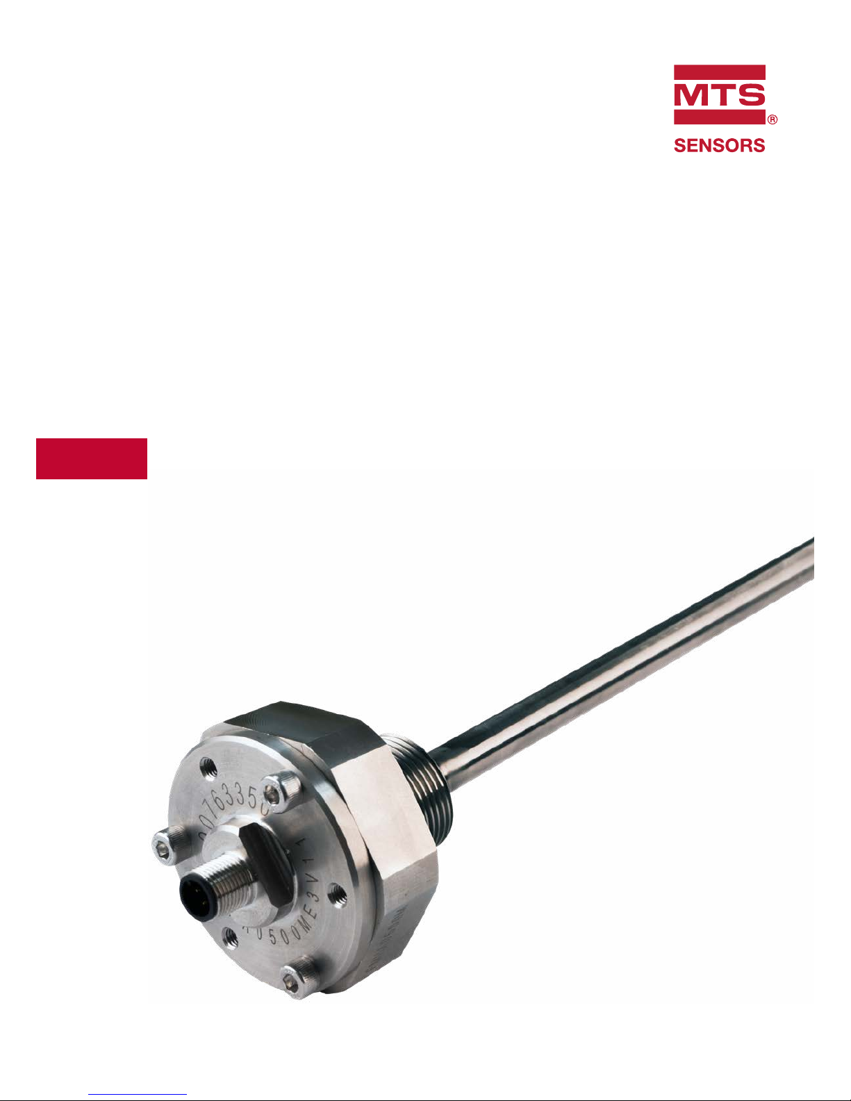
MH-Series Flexible MH
Installation Manual
Temposonics
®
Magnetostrictive Linear Position Sensors

Temposonics® Flexible MH
Operation Manual
Table of contents
1. Introduction ..................................................................................................................................................... 3
1.1 Purpose and use of this manual ................................................................................................................................................................ 3
1.2 Used symbols and warnings ..................................................................................................................................................................... 3
2. Safety instructions ............................................................................................................................................. 3
2.1 Intended use .............................................................................................................................................................................................. 3
2.2 Forseeable misuse ..................................................................................................................................................................................... 3
2.3 Installation, commissioning and operation ................................................................................................................................................ 4
2.4 Safety instructions for use in explosion-hazardous areas .......................................................................................................................... 4
2.5 Warranty .................................................................................................................................................................................................... 4
2.6 Return ....................................................................................................................................................................................................... 4
3. Identification.................................................................................................................................................... 5
3.1 Order code of Flexible MH analog .............................................................................................................................................................. 5
3.2 Order code of Flexible MH CANbus ........................................................................................................................................................... 6
3.3 Nameplate ................................................................................................................................................................................................. 7
3.4 Scope of delivery ....................................................................................................................................................................................... 7
4. Product description and commissioning ................................................................................................................... 7
4.1 Functionality and system design ............................................................................................................................................................... 7
4.2 Styles and installation of Flexible MH ........................................................................................................................................................ 8
4.3 Replacement of sensor ............................................................................................................................................................................ 10
4.3.1 FMH replacement parts ..................................................................................................................................................................... 10
4.3.2 FMH replacement parts ..................................................................................................................................................................... 11
4.4 Electrical connections .............................................................................................................................................................................. 14
4.5 Frequently ordered accessories ............................................................................................................................................................... 15
5. Technical data .................................................................................................................................................16
5.1 Technical data Flexible MH-Series analog ................................................................................................................................................ 16
5.2 Technical data Flexible MH-Series CANbus ..............................................................................................................................................17
6. Appendix .......................................................................................................................................................18
Temposonics® Flexible MH
Installation Manual
I 3 I
1. Introduction
1.1 Purpose and use of this manual
Before starting the operation of Temposonics
®
position sensors,
read this documentation thoroughly and follow the safety
information. Keep the manual for future reference!
Symbol Meaning
NOTICE
This symbol is used to point to situations
that may lead to material damage, but not
to personal injury.
1/ The term qualified technical personnel characterizes persons who:
• are familiar with the safety concepts of automation technology applicable
to the particular project,
• are competent in the field of electromagnetic compatibility (EMC),
• have received adequate training for commissioning and service operations
• are familiar with the operation of the device and know the information required
for correct operation provided in the product documentation.
2. Safety instructions
2.1 Intended use
This product may be used only for the applications defined under item
1 and only in conjunction with the third-party devices and components
recommended or approved by MTS Sensors. As a prerequsite of
proper and safe operation: the product requires correct transport,
storage, mounting and commissioning and must be operat ed with
utmost care.
1. The sensor systems of all Temposonics
®
series are intended
exclu sively for measurement tasks encountered in industrial,
commercial and laboratory applications. The sensors are
considered as system accessories and must be connected
to suitable evaluation electron ics, e.g. a PLC, IPC, indicator
or other electronic control unit.
Foreseeable misuse Consequence
Wrong sensor connection
The sensor will not work
properly or can be damaged
Operate the sensor out of the
operating temperature range
No signal output
The sensor can be damaged
Power supply is out of the
defi ned range
Signal output is wrong /
no signal output /
the sensor can be damaged
Position measurement is
infl uenced by an external
magnetic fi eld
Signal output is wrong
Cables are damaged
Short circuit – the sensor can
be destroyed / sensor does not
respond
Spacers are missing /
installed in wrong order
Error in position measurement
Wrong connection
of ground / shield
Signal output is disturbed
The electronics can be damaged
Use of a magnet that is not
certifi ed by MTS Sensors
Error in position measurement
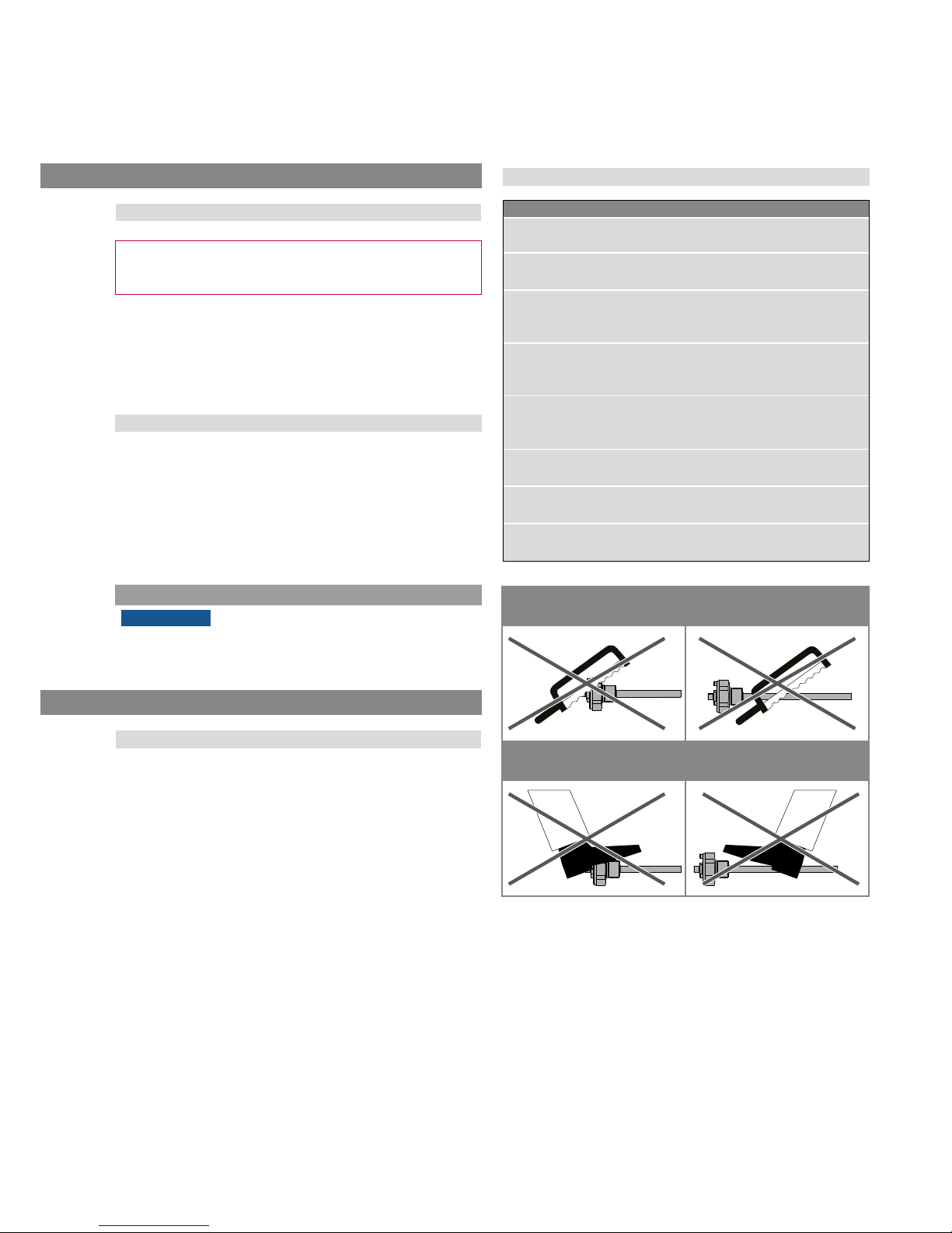
Do not reprocess the sensor afterwards.
The sensor might be damaged.
Do not step on the sensor.
The sensor might be damaged.
2.2 Forseeable misuse
The content of this technical documentation and of its annex is
intended to provide information on mounting, installation and
commissioning by qualified automation personnel
1
or instructed
service technicians who are familiar with the project planning and
dealing with Temposonics
®
sensors.
1.2 Used symbols and warnings
Warnings are intended for your personal safety and for avoidance
of damage to the described product or connected devices. In this
documentation, safety information and warnings to avoid danger
that might affect the life and health of operating or service personnel
or cause material damage are highlighted by the preceding pictogram
which is defined below.

Temposonics® Flexible MH
Installation Manual
I 4 I
2.3 Installation, commissioning and operation
The position sensors must be used only in technically safe condition.
To maintain this condition and to ensure safe operation, installation,
connection and service, work may be performed only by qualified
technical personnel.
If danger of injury to persons or of damage to operating equipment
is caused by sensor failure or malfunction, additional safety measures
such as plausibility checks, limit switches, EMERGENCY STOP
systems, protective devices etc. are required. In the event of trouble,
shut down the sensor and protect it against accidental operation.
Safety instructions for commissioning
To maintain the sensor operability, it is mandatory to follow
the instructions given below.
1. Protect the sensor against mechanical damage during
installation and operation.
2. Do not open or dismantle the sensor.
3. Connect the sensor very carefully and pay attention to the
polarity of connections and power supply.
4. Use only approved power supplies.
5. It is indispensable to ensure that the specified permissible
limit values of the sensor for operating voltage,
environmental conditions, etc. are met.
6. Check the function of the sensor regularly and provide
documentation of the checks.
7. Before applying power, ensure that nobody’s safety
is jeopardized by starting machines.
2.4 Safety instructions for use in explosion-hazardous areas
The sensor is not suitable for operation in explosion-hazardous areas.
2/ See also applicable MTS Sensors sales and delivery on
www.mtssensors.com
2.5 Warranty
MTS Sensors grants a warranty period for the Temposonics
®
position sensors and supplied accessories relating to material
defects and faults that occur despite correct use in accordance with
the intended application
2
. The MTS Sensors obligation is limited to
repair or replacement of any defective part of the unit. No warranty
can be provided for defects that are due to improper use or above
average stress of the product, as well as for wear parts. Under no
circumstances will MTS Sensors accept liability in the event of offense
against the warranty rules, no matter if these have been assured or
expected, even in case of fault or negligence of the company.
MTS Sensors explicitly excludes any further warranties. Neither
the company’s representatives, agents, dealers nor employees are
authorized to increase or change the scope of warranty.
2.6 Return
For diagnostic purposes, the sensor can be returned to MTS Sensors.
Any shipment cost is the responsibility of the sender
2
.
For a corresponding form, see chapter "6. Appendix" on page 18.

Temposonics® Flexible MH
Installation Manual
I 5 I
3.1 Order code of Flexible MH analog
3. Identification
b Design
A M33 thread flange, flat end plug
B M33 thread flange, M4 female plug
Z Base unit (for replacement)
a Sensor model
F M H Flexible MH
1 2 3 4 5 6 7 8 9 10 11 12 13 14
F M H M 3
a b c d e f
f Output
V 1 1
0.25…4.75 VDC
V 1
2 0.5…4.5 VDC
V 1
3 4.75…0.25 VDC
V 1
4 4.5…0.5 VDC
A 0 1
4…20 mA
A 0 4
20…4 mA
e
Operating voltage
3
+12 / 24 VDC (8…32 VDC)
d
Pin assignment
M12 connector (VDC - GND - SIG)
E M12 connector (E: 2-3-4)
G
M12 connector (G: 1-3-4)
H
M12 connector (H: 1-3-2)
c Stroke length
X X X X
M 0500…5000 mm (20 mm increments)

Temposonics® Flexible MH
Installation Manual
I 6 I
3.2 Order code of Flexible MH CANbus
1 2 3 4 5 6 7 8 9 10 11 12 13 14 15 16 17
F M H M F 3 0 1
a b c d e f g h
b Design
A M33 thread flange, flat end plug
B M33 thread flange, M4 female plug
Z Base unit (for replacement)
a Sensor model
F M H Flexible MH
c Stroke length
X X X X
M 0500…5000 mm (20 mm increments)
e Operating voltage
3
+12 / 24 VDC (8…32 VDC)
g Baud rate setting
CANopen
0
1000 kbit/s
1
800 kbit/s
2
500 kbit/s
3
250 kbit/s (default)
4
125 kbit/s
SAE J1939
3
250 kbit/s (fix setting)
f Output
C
0
1
CANopen
J
0
1
SAE J1939
h Node ID
CANopen
7 F Node ID (hex): 01…7F (default: 7F)
SAE J1939
F D Node ID (hex): 01…FD (default: FD)
d Pin assignment
M12 connector (VDC - GND - CAN_HI - CAN_LO)
F M12 connector (F: 2-3-4-5)
 Loading...