

MTS Sensors Temposonics M, Temposonics MH Datasheet
®
Temposonics
Magnetostrictive, Absolute, Non-contact
Linear-Position Sensors
®
SENSORS
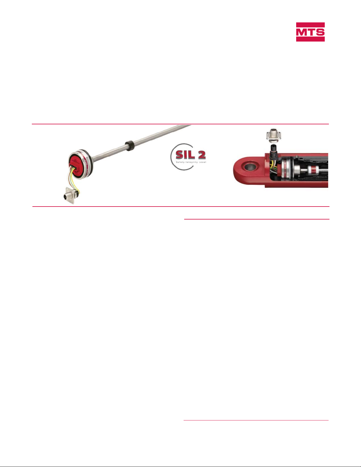
M-Series Mobile Hydraulic
In-Cylinder Sensor
Model MH CAN Safety (SIL 2)
FEATURES
Linear, Absolute Measurement in Hydraulic Cylinders
Non-Contact Sensing Technology
Superior Accuracy, < ± 0.04% F.S.
Hysteresis < ± 0.1 mm
Repeatability, < ± 0.005% F.S.
Compact Design for Embedded Cylinder Applications
Direct CAN Safety Output:
Displacement + Velocity
Stroke length: 50 mm (2 in.) to 2500 mm (98 in.)
Voltage input: 12/24 Vdc
Shock Rating: 100 g (single hit) / IEC 68-2-27
Vibration Rating 25 g / 10-2000 Hz/IEC 68-2-6
200 V/m EMI Immunity
BENEFITS
Rugged Mobile Sensor
SIL2 Safety Integrity Level
CAN Safety (SIL 2) Output
Data Sheet
Document Part Number
551194 Revision B
Cylinder Application ExampleM-Series Model MH Sensor
Product overview
The M-Series Model MH sensor is designed with the “mobile” world
in mind. The Model MH sensor is validated in the field by customers
worldwide. Performance is second-to-none with high EMI resistance
of 200 V/m. Ruggedness is “designed in”; 100 g shock and 25 g vibration rating. The model MH CAN Safety sensor can be fully sealed and
embedded in a cylinder to ensure a long operating life.
The absolute, non-contact Temposonics position sensor with CAN
Safety reaches a level of 95% for SFF at a fault to ground of 0 for the
hardware. Since they are approved for SIL 2 level, they have an average probability for Failure (PFH) in the range of ≥10
A SIL Safety manual and direct connection to the Temposonics
M12x1 connector system and other proven mobile connectors are
available.
-7
to <10-6 per year.
®
APPLICATIONS
Continuous Operation In Harsh Mobile Conditions
High Pressure Conditions
For Welded and Tie-rod Cylinder Applications
TYPICAL INDUSTRIES
Construction
Agriculture
Off-highway Machinery
All specifications are subject to change. Contact MTS for specifications and
engineering drawings that are critical to your application. Drawings contained
in this document are for reference only. Go to http://www.mtssensors.com for
the latest support documentation and related media.

M-Series Model MH CAN Safety Sensor
Product Overview and Specification
Product specifications
Parameters Specifications
INPUT/OUTPUT
Measured
variable: Linear position and velocity
Output: Direct CAN Safety acc. CiA DS-304
Resolution: Consistent: > 1 mm/s
CAN Safety ≤ ± 0.1 mm
Signal output frequency:
CAN Safety adjustable 1 ms to 65535 ms or
Sync. mode
Velocity: Typical 1 m/s
Stroke length: 50 mm to 2500 mm (2 in. to 98 in.)
Measured in 5 mm (0.20 in.) increments
Linearity
uncorrected:
50 to 250 mm ≤± 0.1 mm
255 to 2000 mm < ± 0.04% full stroke
(minimum ± 0.100 mm 0.003 in.)
< ± 0.08% full stroke (for short damping zone)
500 mm ≤± 0.2 mm
750 mm ≤± 0.3 mm
1250 mm ≤± 0.5 mm
2005 to 2500 mm ≤± 0.8 mm
Hysteresis: ± 0.1 mm (0.003 in.)
Cycle time: 1 ms
Setpoint
tolerance: ± 0.2 mm (0.007 in.)
Operating
voltage:
12/24 Vdc (8-32 Vdc)
Voltage supply ripple: <1 % p-p
Power drain: < 1.5 W
ELECTRONICS
Electrical
isolation: 500 Vdc (DC ground to machine ground)
Polarity
protection: Up to -36 Vdc
Overvoltage
protection: Up to 36 Vdc
Parameters Specifications
ENVIRONMENTAL
Operating
conditions:
Operating: any orientation, -40 °C (-40 °F) to
+105 °C (221 °F)
Storage: -30 °C (-22 °F) to +105 °C (221 °F)
90% relative humidity, no condensation
EMC test: 200 V/m
ISO 11452-5
ISO 14982: Agriculture and forest machinery
Shock rating: 100 g (single hit)/IEC standard 68-2-27
(survivability)
25 g / 10 to 2000 Hz /IEC standard 68-2-6
Vibration
rating:
Sensor rod, 10 mm (0.39 in.): 25 g
Sensor rod, 7 mm (0.27 in.): 15 g
WIRING
Connection
type:
One 5-wire with the M12x1 connector
and flange (provides IP69K environmental
protection when installed in a cylinder).
ROD STYLE SENSOR (Model MH)
Material: Sensor rod: Stainless steel 1.4306 / AISI
304L
Housing: Stainless steel 1.4305 / AISI 303
Mechanical assembly: Flange housing 48 mm
(1.89 in.) dia., O-ring 40.87 x 3.53 mm NBR
80, backup ring 42.6 x 48 x 1.4 PTFE
Sealing: IP67 (IP69k when installed inside a cylinder
with M12 x 1 in. connection type)
Pressure
rating:
Sensor rod, 10 mm (0.39 in.):
Operating, 350 bar (5076 psi)
Peak, 450 bar (6615 psi)
Sensor rod, 7 mm (0.27 in.):
Operating, 300 bar (4350 psi)
Peak, 400 bar (5800 psi)
Pressure pulse test acc.: DIN EN ISO 19879
Magnet type: Ring magnet (see standard magnet selections)
M-Series Model MH Temposonics® Position Sensor for Mobile Hydraulics, CAN Safety (SIL 2)
Product Data Sheet, Document Part No.: 551194, Revision B 02/12, 05/12, 08/12
2
MTS Sensors
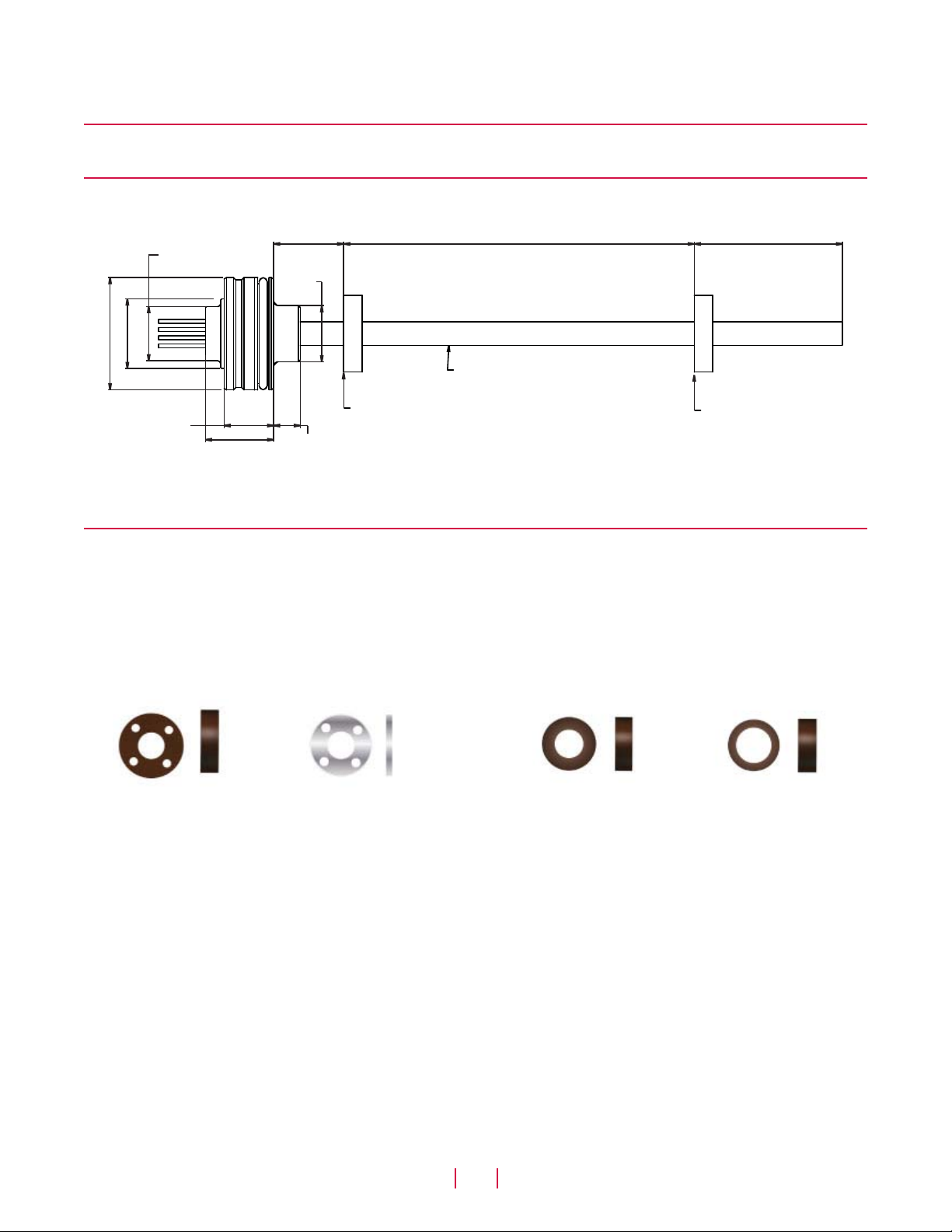
M-Series Model MH CAN Safety Sensor
Output, Dimension and Magnet References
Output options
The M-Series Model MH position CAN Safety sensor provides direct CAN Safety output.
Model MH sensor dimension references
Model MH, rod-style Redundant Sensor Drawing is for reference only, contact applications engineering for tolerance specific information.
Null
23 mm
(0.9 in.) dia.
30 mm
(1.18 in.) dia.
48 mm (1.88 in.) dia.
21.2 mm
(0.83 in.)
+0 / -0.2
+0 / -0.007
30 mm
(1.18 in.)
30 mm
(1.18 in.)
24 mm
(0.94 in.)
dia.
11.5 mm
(0.45 in.)
50 mm (1.96 in.) to 2500 mm (98.42 in.)
Stroke length
7 mm (0.27 in.) dia. or
10 mm (0.39 in.) dia.
Stroke length start ‘Null’ position
Dead zone
63.5 mm (2.49 in.) or
36.5 mm (1.44 in.)
Stroke length end ‘Span’ position
Figure 1. M-Series Model MH rod-style sensor dimension reference
Standard magnet selections (Model MH)
SELECTION OF POSITION MAGNETS (MAGNET AND MAGNET SPACER MUST BE ORDERED SEPARATELY)
A choice of three magnets are available with the Model MH rod-style sensor. Magnets must be ordered separately with Model MH position
sensors. The standard ring magnet (part number 201542-2) is suitable for most applications.
STANDARD RING MAGNET
Part number 201542-2
(used with magnet part no.: 201542-2)
Material: Ferrite PA
I.D.: 13.5 mm (0.53 in.)
O.D.: 33 mm (1.3 in.)
Thickness: 8 mm (0.3 in.)
Operating temperature:
- 40 °C (-40 °F) to
- 105 °C to (221 °F)
MAGNET SPACER
Part number 400633
Material: Non-ferrous
Used with ring magnet (part no.:
201542-2)
I.D.: 14 mm (0.56 in.)
O.D.: 32 mm (1.25 in.)
Thickness: 3.2 mm (0.125 in.)
RING MAGNET
Part number 400533
Material: Ferrite PA
I.D.: 13.5 mm (0.53 in.)
O.D.: 25.4 mm (1 in.)
Thickness: 8 mm (0.3 in.)
Operating temperature:
- 40 °C (-40 °F) to
- 105 °C to (221 °F)
RING MAGNET
Part number 401032
Material: Ferrite PA
I.D.: 13.5 mm (0.53 in.)
O.D.: 17 mm (0.68 in.)
Thickness: 8 mm (0.31 in.)
Operating temperature:
- 40 °C (-40 °F) to
- 105 °C to (221 °F)
MTS Sensors
3
M-Series Model MH Temposonics® Position Sensor for Mobile Hydraulics, CAN Safety (SIL 2)
Product Data Sheet, Document Part No.: 551194, Revision B 02/12, 05/12, 08/12
 Loading...