

MTS Sensors Temposonics Operation Manual
OPERATION MANUAL
High Pressure Housing (HPH)
The Measurable Difference
Temposonics
®
Magnetostrictive Linear Position Sensors
ATEX
Operation Manual
High Pressure Housing
I 2 I
Safety Instructions
The sensor must only be used according to the EX-certifi cate no.
Demko 07 ATEX 142619X or UL listing no. 2PD0 See product name
plate for actual approvals.
To reduce risk of ignition in hazardous atmospheres, disconnect the
equipment from the supply circuit before opening. Keep assembley
tightly closed when in operation.
For use according to UL-listing, conduit seals must be installed within
18" of the inclosure. Must be connected to a Class 2 power supply
The housing parts must be kept as one unit.
They are not interchangeable with parts from similar housings.
Only tools applicable for use in explosive atmosphere must be used.
When mounting the rod in “ZONE 0” it is necessary to prevent any
leakage between “ZONE 0” and the surrounding environment.
The sensor house must be connected to an equipotential bonding
system or an earthing system.
PRECISION POSITION MEASUREMENT – HPH
This High Pressure Housing (HPH) is ATEX-IECEx as well as UL and
cUL approved for use in hazardous locations with Temposonics
®
position sensors. The ATEX, UL and cUL approvals cover fl ammable
gases, vapors, liquids and dust.
This housing is made to fi t Temposonics
®
G-Series Analog + Start/Stop
Sensors and R-Series sensors with analogue and digital outputs.
Both fi xed cable and connector versions can be used. When using
a standard sensor in this housing you get a cost effi cient solution for
use in hazardous locations which also allows easy sensor replacement.
Several design combinations are available to fi t your application:
M18 or ¾"UNF mounting fl ange - M20 or ½" NPT cable
gland thread - top mounted or single/dual side-mounted. See combination chart. All parts are made of 316L stainless steel. The housing
is also available in non-approved versions ensuring an outstanding
protection to the sensor when used in rigged applications with high
humidity and agressive gases.
TECHNICAL DATA
ATEX, IECEx
IECEx TUN 13 0011 X
II ½ G Ex d IIC T5 Gb Tamb -40 ºC to +75 ºC
(1)
II ½ D Ex tb IIIC T100C Db
In accordance with IEC 60079-0:2011, IEC 60079-1:2007, IEC 60079-26:2006,
IEC 60079-31, EN 60079-0:2009, EN 60079-1:2007, EN 60079-26:2007,
EN 60079-31:2009
Only with ATEX and IECEx approved cable glands
Class 1, Devision 1, Groups A, B, C, and D hazardous
locations, temperatur code T5
As to fi re, electrical shock and explosion hazards only
UL certifi
cated no. 2PD0.
In accordance with UL 1203 standard.
Only with UL approved cable glands
Material Stainless steel AISI 316L (1.4404)
Cable gland threads M20 × 1.5 or ½" NPT
Ingress protection code IP68 (only with IP68 approved cable gland)
Approved sensors G-Series Analog+Digital
R-Series Analog
R-Series Profi bus
R-Series CANBUS
R-Series SSI
R-Series DeviceNet
Mounting fl ange M18 × 1,5 or ¾" - 16UNF - 3A
Pressure rating 350 bar
Peak pressure 530 bar
Magnet type Ring magnets
Level Measurement Float on request
Operating temperature −40…+75 ºC
(1)
2/ T
amb
+ is limited to max T
amb
+ of used sensor −10ºC
Operation Manual
High Pressure Housing
I 3 I
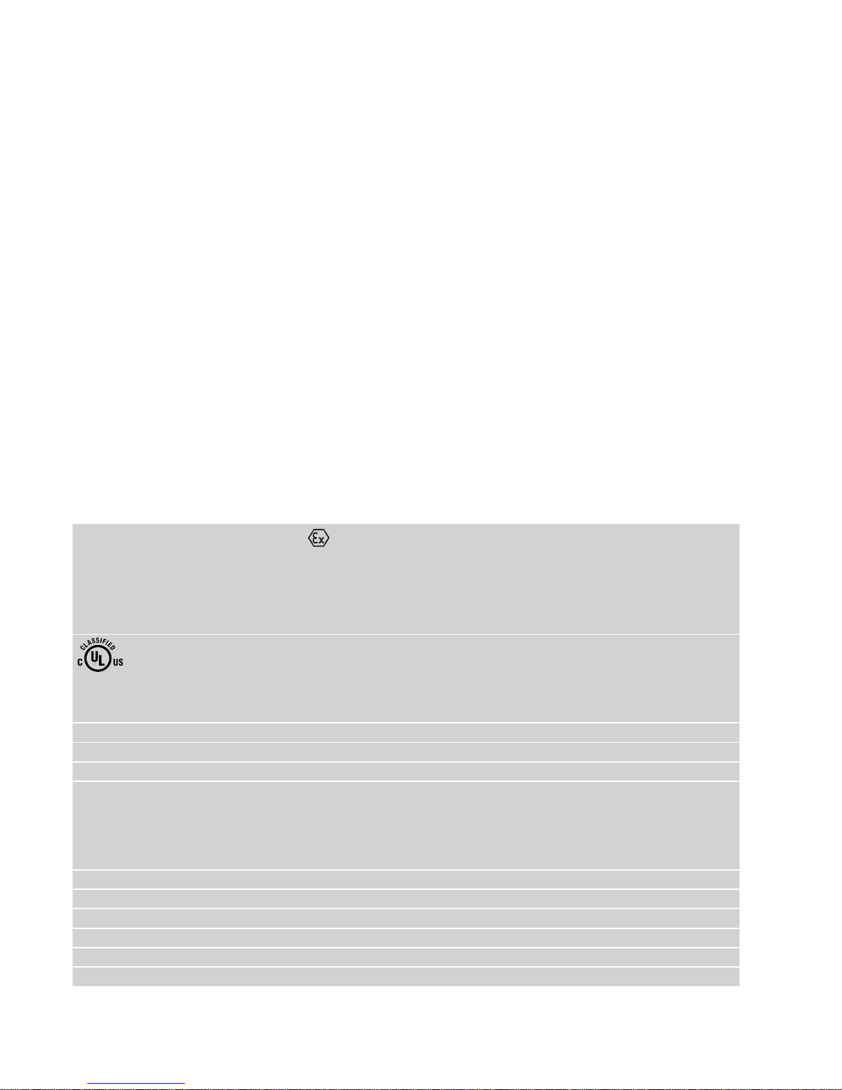
TECHNICAL DRAWING
All dimensions in mm
147…198
19.5
Ø 85
Ø 60
M18 or 3/4"
25
51 Measuring Length 50…7500
Mounting
Zone
Ø 10
*64
Damping
Zone
Zone 1 Zone 0
* Measuring length > 5000 mm = 66 mm
M5
Ø 64
Ø 85
Ø 69
8625
Short top 158 / Long top 198
Ø 64
Ø 85
Ø 69
8625
Short top 147 / Long top 187
56
M20 or
1/2" NPT
M18 or
3/4" NPT
Top mounted cable gland Side mounted cable gland
Operation Manual
High Pressure Housing
I 4 I
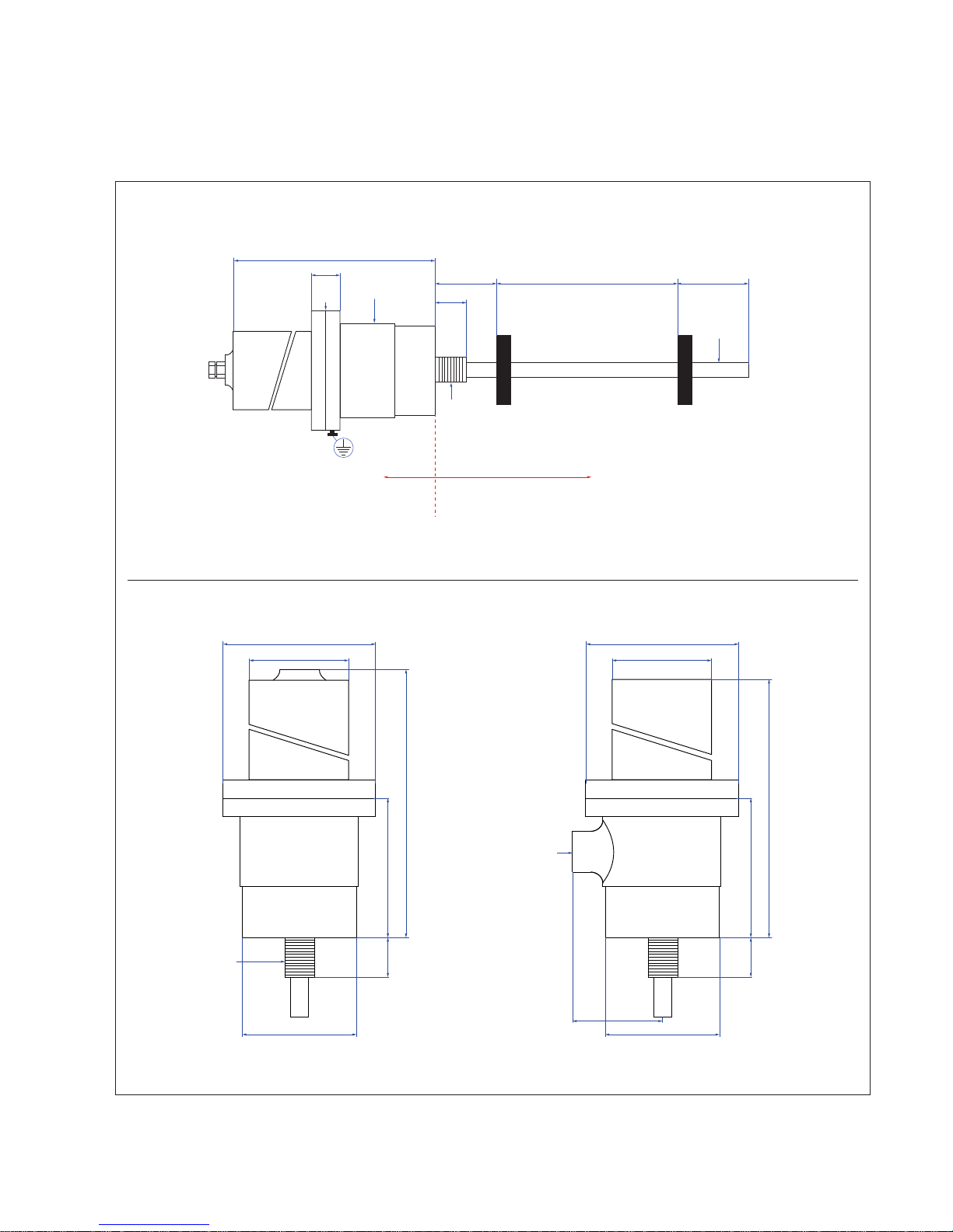
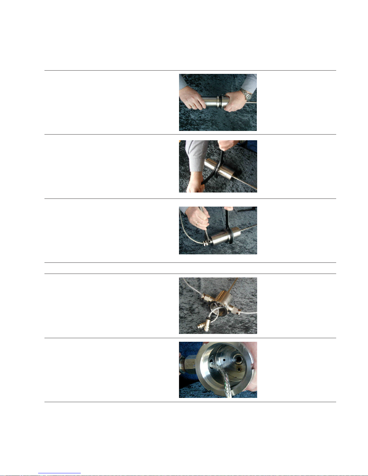
1.
Open the housing by turning the top counter clockwise.
When opening after a sensor is installed, it is very important to completely loosen the cable gland in order to
protect the cable against twisting and physical damage.
The normal way is that the sensor and the HPH housing
are in one order and then MTS Sensors supply the sensor mounted in the WPH housing. Go to step 7.
2.
Remove rod or profile from the sensor.
Separate the plastic tube from the sensor.
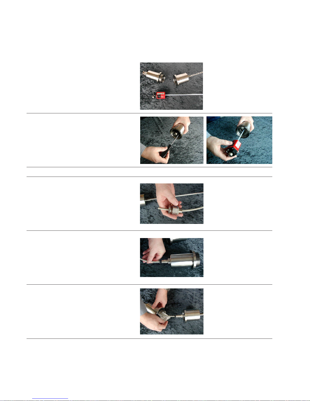
3. Cable gland
3.1 Insert the cable through the gland
3.2 Insert the connector through the top.
3.3
Connect to the sensor and insert a bag of
Desiccant in the top.
MOUNTING DISCRITPION
Operation Manual
High Pressure Housing
I 5 I
3.4 Assemble the top and bottom turning clockwise.
3.5
Tighten firmly until the top and bottom flanges
come together.
3.6
Tighten gable gland according to the manufacturer’s
specifications.
4. Side mounted cable gland(s)
4.1 Enter the cable through the gland without tightening.
4.2
For cable sizes larger than 7mm or very rigid cables,
you may need to remove the outer insulation jacket
from inside the cable gland to the connector
 Loading...