

MTS Sensors MH User Manual
The MH-Series Analog/PWM Tester supports analog, 4 - 20 mA and 0 - 10 Vdc,
scaled Pulse Width Modulated (PWM), and PWM time of flight (tOF) sensor
outputs. The MH-Series tester is a battery powered device that is be used in test
bench and field applications to verify that the MTS Sensor is functioning properly
and is producing the appropriate signal outputs.
FEATURES:
Easy connection to MTS’ M12 integrated connector system
Easy to use push-button controls
Supports voltage (0-10 Vdc) and current (4-20 mA) outputs
Supports scaled PWM and time-of-ight PWM outputs
Compact construction for use in eld applications
Provides both +5 Vdc and +12Vdc sensor power supply
Sealed lead acid battery that provides up to 8 hours of operation per
charge
Battery level monitoring
Automatic detection of PWM sensor frequency
Carrying case
All specifications are subject to change. Contact MTS for specifications and engineering
drawings that are critical to your application. Drawings contained in this document are for
reference only. Go to www.mtssensors.com for the latest support documentation.
Temposonics
®
Magnetostrictive
Linear-Position Sensors
User’s Guide
551132 B
MH-Series Analog / PWM Tester
MH-Series Analog / PWM Tester

MH-Series Analog / PWM Test Kit - User’s Guide (Part No. 551132B) MTS Sensors
Contents
Section 1.0 The MH-Series Analog / PWM Test Kit
1.1 Contents and accessories ............................................... 3
1.2 Familiarizing yourself with the MH-Series tester .........4
1.2.1 Front panel ...........................................................4
1.2.2 Top panel .............................................................5
Section 2.0 Installation
2.1 Connecting analog sensors ............................................ 6
2.2 Connecting PWM Sensors ............................................. 7
2.3 SLA battery charger setup .............................................. 8
2.4 AC Power plug adapter connection / replacement .......... 8
2.5 Quick start instruction label ........................................ 10
Section 3.0 Operation
3.1 Startup .........................................................................11
3.2 Mode selections ........................................................... 12
3.2.1 Voltage (Volt) .........................................................12
3.2.2 Current (Curr) ........................................................12
3.2.3 Battery level (Batt) ................................................. 12
3.2.4 Battery charging ....................................................13
3.2.5 Scaled PWM (Puum) ............................................ 14
3.2.6 Time of Flight PWM .............................................. 15
3.3 Verification .................................................................. 17
3.4 Troubleshooting ...........................................................17
Contact and Support Information
2
General:
Tel: (919) 677-0100
Fax: (919) 677-0200
E-mail: sensorsinfo@mts.com
http://www.mtssensors.com
Mailing and Shipping Address:
MTS Systems Corporation
Sensors Division
3001 Sheldon Dr.
Cary, NC USA 27513
Customer Service:
Tel: (800) 633-7609
Fax: (800) 498-4442
Office Hours (EST):
Monday - Thursday:
8:00 a.m. to 5:00 p.m.
Friday: 8:00 a.m. to 4:00 p.m.
Quote and Contract Terms & Conditions:
The parties expressly agree that the
purchase and use of Material and/or
Services from MTS Sensors Division are
subject to MTS’ Terms and Conditions,
in effect as of the date of this document,
which are located at http://www.
mtssensors.com/fileadmin/media/pdfs/
Terms_and_Conditions.pdf and are
incorporated by reference into this and
any ensuing contract. Printed Terms and
Conditions can be provided upon request
by emailing info@mtssensors.com or if
you prefer, go to http://www.mtssensors.
com/index and click the Quote/Contract
Terms and Conditions link at the bottom
of the page to download the PDF.
Related publications:
Product Specification, MH-Series Analog /
PWM Test Kit, Part no. 551139. Download
the (PDF) http://www.mtssensors.com.
MTS Sensors MH-Series Analog / PWM Test Kit - User’s Guide (Part No. 551132B)
1.0 - The MH-Series Analog / PWM Test Kit
1.1 Contents and Accessories
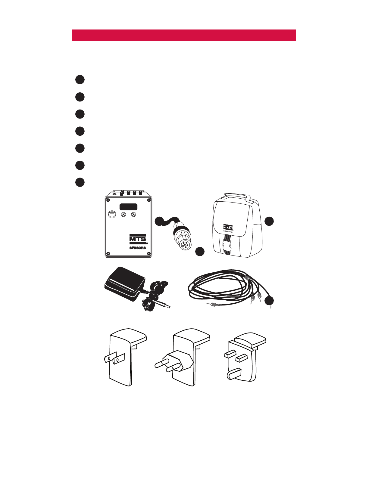
The MH-Series Analog / PWM Test Kit includes:
1
MH-Series Analog / PWM Tester
2
12 Vdc Sealed Lead Acid (SLA) battery charger with adapter
3
Cable with MTS’ M12 integrated connector system and banana plugs
4
Pigtailed cable with banana plugs
5
Carrying case (part no. 561924)
6
User’s Guide (part no. 551132, not pictured)
7
Quick start instruction label (part no. 551656, not pictured)
Power Plug Adapter,
North America
Power Plug Adapter,
European Union
Power Plug Adapter,
United Kingdom
AB
POWER
www.mtssensors.com
3
1
2
3
5
4
MH-Series Analog / PWM Test Kit - User’s Guide (Part No. 551132B) MTS Sensors
1.0 - The MH-Series Analog / PWM Test Kit (continued)
1.2 Familiarizing yourself with the MH-Series Tester
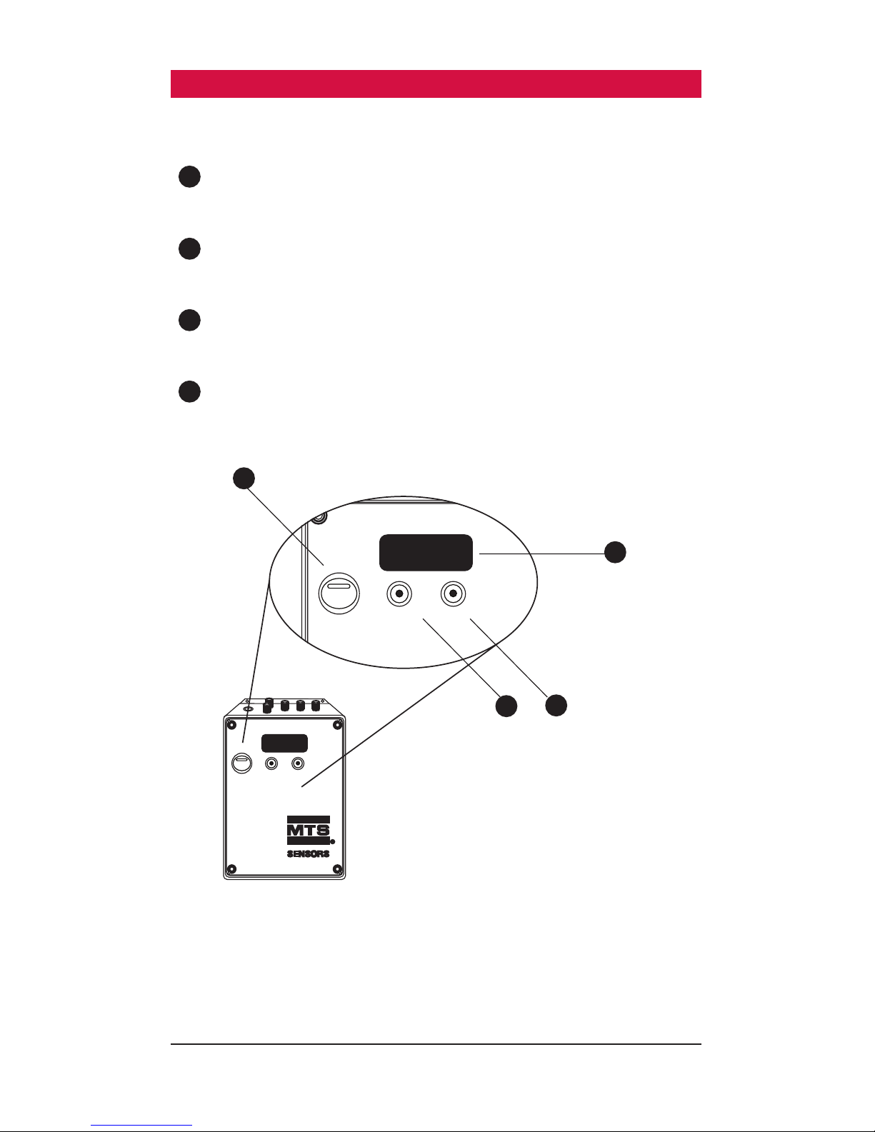
1.2.1 Front panel
1
LCD panel
Tester LCD panel displays sensor output, settings, and battery level
2
Power switch
Toggle to turn the MH-Series Tester ‘ON’ and ‘OFF’
3
Mode button ‘A’
Press to change transducer modes and to reset system
4
Special function button ‘B’
Press to change recirculation values in PWM / tOF mode and to reset
system
3
4
1
2
AB
POWER
www.mtssensors.com
AB
POWER
4
MTS Sensors MH-Series Analog / PWM Test Kit - User’s Guide (Part No. 551132B)
1.0 - The MH-Series Analog / PWM Test Kit (continued)
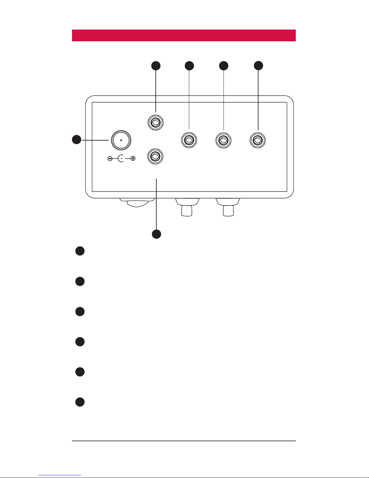
1.2.2 Top panel
1
Charger port
Port used to charge the internal SLA battery
2
+5 Vdc port
Sensor 5 volt supply connection (Not an input port)
3
+12 Vdc port
Sensor 12 volt supply connection (Not an input port)
4
GND
Sensor ground connection
5
Analog port
0-10 Vdc or 4-20 mA sensor output connection
6
PWM port
PWM (Scaled) or PWM (tOF) sensor output connection
1
2
4
5
6
−+−
+
+5V
PWM
ANA
GND
+12V
3
5
MH-Series Analog / PWM Test Kit - User’s Guide (Part No. 551132B) MTS Sensors
2.0 Installation
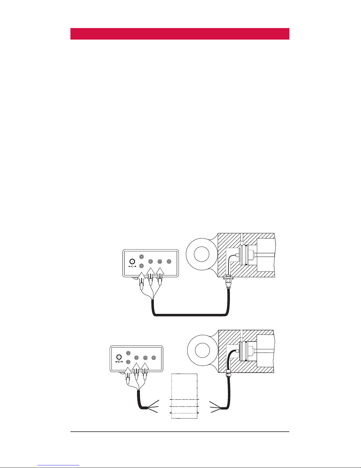
2.1 Connecting an analog sensor
To connect an Analog sensor equipped with MTS’ M12 integrated connector
system to the MH-Series Tester use the following procedure:
1. Use the provided cabling fitted with the M12 connector
and connect the M12 cable to the MTS M12 integrated connector
system on the sensor or cylinder. (continue with step 3 below) OR
To connect an Analog Sensor not equipped with MTS’ M12 integrated connector
system:
1. Use the Pigtailed cable that is included in the test kit to connect the ends
without banana plugs to the customer’s specified interface/connector
that mates to the MH-Series Sensor or cylinder.
2. Ensure that the wire colors of the cable correspond with the wire colors
of the output wires from the sensor.
3. Plug the brown banana plug into the +12 Vdc or +5 Vdc (depending on
voltage required by the sensor) terminal on the top of the tester.
4. Plug the white banana plug into the DC GND terminal on the top of
the tester.
5. Plug the green banana plug into the analog terminal at the top of
the tester.
−+−
+
+5V
PWM
ANA
GND
+12V
Green
White
Brown
M12 Cable Assembly
Select sensor
supply voltage
(+12V or +5V)
Select sensor
supply voltage
(+12V or +5V)
CUSTOMER
SPECIFIED
INTERFACE/
CONNECTOR
−+−
+
+5V
PWM
ANA
GND
+12V
White
Green
Brown
White
Green
Brown
White
Green
Brown
Sensor cable
Pigtail cable
assembly
6
 Loading...